EP3138975B1 - Kit zum stellen von wänden - Google Patents
Kit zum stellen von wänden Download PDFInfo
- Publication number
- EP3138975B1 EP3138975B1 EP15785791.3A EP15785791A EP3138975B1 EP 3138975 B1 EP3138975 B1 EP 3138975B1 EP 15785791 A EP15785791 A EP 15785791A EP 3138975 B1 EP3138975 B1 EP 3138975B1
- Authority
- EP
- European Patent Office
- Prior art keywords
- tubular
- coupling
- panels
- prop
- tubular element
- Prior art date
- Legal status (The legal status is an assumption and is not a legal conclusion. Google has not performed a legal analysis and makes no representation as to the accuracy of the status listed.)
- Active
Links
Images




Classifications
-
- E—FIXED CONSTRUCTIONS
- E04—BUILDING
- E04G—SCAFFOLDING; FORMS; SHUTTERING; BUILDING IMPLEMENTS OR AIDS, OR THEIR USE; HANDLING BUILDING MATERIALS ON THE SITE; REPAIRING, BREAKING-UP OR OTHER WORK ON EXISTING BUILDINGS
- E04G21/00—Preparing, conveying, or working-up building materials or building elements in situ; Other devices or measures for constructional work
- E04G21/24—Safety or protective measures preventing damage to building parts or finishing work during construction
- E04G21/243—Safety or protective measures preventing damage to building parts or finishing work during construction for creating a temporary partition in a closed room
-
- E—FIXED CONSTRUCTIONS
- E04—BUILDING
- E04B—GENERAL BUILDING CONSTRUCTIONS; WALLS, e.g. PARTITIONS; ROOFS; FLOORS; CEILINGS; INSULATION OR OTHER PROTECTION OF BUILDINGS
- E04B2/00—Walls, e.g. partitions, for buildings; Wall construction with regard to insulation; Connections specially adapted to walls
- E04B2/74—Removable non-load-bearing partitions; Partitions with a free upper edge
- E04B2/82—Removable non-load-bearing partitions; Partitions with a free upper edge characterised by the manner in which edges are connected to the building; Means therefor; Special details of easily-removable partitions as far as related to the connection with other parts of the building
- E04B2/821—Connections between two opposed surfaces (i.e. floor and ceiling) by means of a device offering a restraining force acting in the plane of the partition
-
- E—FIXED CONSTRUCTIONS
- E04—BUILDING
- E04F—FINISHING WORK ON BUILDINGS, e.g. STAIRS, FLOORS
- E04F13/00—Coverings or linings, e.g. for walls or ceilings
- E04F13/07—Coverings or linings, e.g. for walls or ceilings composed of covering or lining elements; Sub-structures therefor; Fastening means therefor
- E04F13/21—Fastening means specially adapted for covering or lining elements
- E04F13/24—Hidden fastening means on the rear of the covering or lining elements
-
- E—FIXED CONSTRUCTIONS
- E04—BUILDING
- E04B—GENERAL BUILDING CONSTRUCTIONS; WALLS, e.g. PARTITIONS; ROOFS; FLOORS; CEILINGS; INSULATION OR OTHER PROTECTION OF BUILDINGS
- E04B2/00—Walls, e.g. partitions, for buildings; Wall construction with regard to insulation; Connections specially adapted to walls
- E04B2/74—Removable non-load-bearing partitions; Partitions with a free upper edge
- E04B2002/7461—Details of connection of sheet panels to frame or posts
- E04B2002/7462—Details of connection of sheet panels to frame or posts using resilient connectors, e.g. clips
Definitions
- the present invention relates to a kit for erecting walls including a plurality of props, cladding panels and securing devices.
- Said prop applies axial pressure against two parallel planes by means of the elastic element, providing active propping, and the extendable nature of the prop allows said prop to be easily installed and removed without labor, as well as allowing the pressure exerted by the elastic element to be regulated.
- the prop can be used as a structure for dry-mounted cladding by means of removably securing cladding panels to tubular elements, especially to securing devices in the form of a spring clip suitable for being anchored to a tubular element and provided with coupling means suitable for the anchoring of one or more cladding panels.
- extendable props provided with an elastic element for being fitted between two parallel planes.
- Patent document DE202004016792U describes props of this type which integrate at their upper end an elastic element as well as a threaded element for expanding the prop, increasing the force exerted by the prop on the floor and ceiling, and are used as support for holding partitions for dividing spaces, especially offices.
- the upper and lower ends of this solution have a bell shape to increase the contact surface area, which prevents the cladding from covering said upper and lower ends.
- This prior art does not propose a divisible prop, so it will be hard and costly to handle and transport.
- Patent document GB695937 also describes an element with similar features, and in this case the prop is divided into two telescopically attached segments of different diameter, and it includes an elastic element and a threaded element for regulating the total length of the prop, and for including elastic strain for fitting the prop, but, besides having two segments of different diameter, a pin must be introduced to work as a stop, and the threaded element acts on said pin to separate the two segments.
- Patent document US4449876 describes a threaded element integrated with an element elastically movable with a spring, and both are integrated with a connecting element which allows coupling this device to the end of a wooden prop, so that it can be fitted inside a vehicle for securing a load.
- This embodiment does not include any tubular element in which said threaded or movable elements are inserted.
- the coupling thread attaching the threaded element to the rest is part of the movable element, and can therefore move as it is free.
- the coupling thread has a rectangular shape and is inserted in a rectangular compartment.
- Cladding can be secured on the extendable prop by means of securing devices of the type having two elastically deformable arms arranged opposite one another which can be anchored to and released from the prop, and are attached to a coupling means complementary with the cladding panels.
- Patent document DE202006005611 describes an embodiment of said securing device, but it is not envisaged for coating two opposite faces of one and the same group of props, or for allowing the cladding panels of both faces to be arranged opposite one another.
- Patent document FR2936827 also describes a similar product with the same drawbacks.
- Documents describing securing devices that can be coupled to a tubular element and provided with a coupling means which allows securing panels are also known.
- Document EP1850045A describes support clips for pipes having elastically deformable arms arranged opposite one another and attached to a support which integrates a coupling means.
- Documents DE29500415U and CA2739414 describe extensible props.
- Document US2855037 describes a kit for erecting walls including props and cladding panels, but not using a clipping system to attach said cladding panels to the props.
- the present invention relates to a kit for erecting walls including a plurality of extendable props, cladding panels and securing devices according to claim 1.
- the threaded element thereby allows increasing or reducing the total length of the extendable prop by rotating with respect to the coupling thread, adapting the total length of the extendable prop to the distance existing between two parallel planes between which said extendable prop is to be fitted.
- the threaded element can be a cylindrical body with one or more threads on its outer face, and can be inserted into the tubular element, in which there is arranged the coupling thread which can consist of one or more female threads made directly on the inner face of said tubular element, or consist of a bushing having a coupling thread with an inner cylindrical cavity on which one or more threads have been made, said bushing having a coupling thread being fixed to the tubular element.
- the thread pitch can also be of different amplitude to achieve faster or slower regulation of the threaded element. Having several threads allows providing a greater or the same thread pitch, providing a tooth with the same or smaller height than if there were only a single thread.
- Said elastic element is attached to a movable element which is in turn attached, in a manner movable in the longitudinal axial direction, to the tubular element of the prop, such that when compressing the extendable prop in said direction, relative movement between the movable element and the tubular element of the prop occurs, offering elastic strength provided by the elastic element.
- Said elastic element can be, in a non-limiting preferred manner, a spring with one of its ends secured with respect to the tubular element of the prop by means of a flange, a stop or a pin, for example.
- Other solutions consisting of equivalent elastic elements, such as the use of a pneumatic piston or an elastomer, for example, are also accepted.
- Said movable element can be an element with an outer section having a size smaller than the inner section of the hollow profile into which it is inserted, being house loosely therein and allowing relative longitudinal movement.
- the tubular element of the prop is made up of a plurality of tubular segments with the same sized outer section arranged coaxial and coaligned with one another, all the tubular segments forming the tubular element of the prop being susceptible of being attached to one another by means of at least one connecting element.
- Said plurality of tubular segments can be, in a non-limiting manner, a first tubular element and a second tubular element.
- the plurality of tubular segments can include additional tubular elements that can be attached to the first and second tubular elements for obtaining a longer prop, or segments of shorter and therefore more manageable tubular element.
- Said additional tubular elements will have the same outer section as the first and second tubular elements, and will be connected to one another or to said first and second tubular elements by means of the threaded element, the movable element, the connecting element, or by means of additional connecting elements.
- each individual tubular segment is less than three fourths the total length of the extendable prop when fully extended, and it is preferably half the length of the tubular element of the prop if there are no additional tubular elements, and one third or one fourth the length of the tubular element of the prop if there are one or two additional tubular elements, respectively, they can therefore be transported in an easy and cost-effective manner in a shorter packet, or can even be delivered by a courier service, reducing logistics costs, and making long-distance selling and purchasing easier.
- Each of the tubular segments of the plurality of tubular segments will preferably have a length less than 110 cm.
- tubular segments can be made of a metallic material, preferably aluminum, and have a protective surface finish, such as anodizing, lacquering, varnishing, galvanizing, painting, or any other surface finish, and can have an outer finish that is smooth, fluted, jagged, with notches or with holes.
- a protective surface finish such as anodizing, lacquering, varnishing, galvanizing, painting, or any other surface finish, and can have an outer finish that is smooth, fluted, jagged, with notches or with holes.
- the connecting element which allows attaching two tubular segments to one another can be, by way of example, an element with an outer section having a size equal to or slightly smaller than the inner section of one of said tubular segments, thereby allowing an unskilled user to manually insert a portion of said connecting element in a tight-fitting manner into each of the tubular segments without using any tools, thereby providing a rigid attachment.
- relative rotation between said connecting element and the tubular segment can be allowed, and said rotation can be made easier by means of using materials with a low coefficient of friction, such as Teflon, or lubricating products, for example.
- connection elements such as threaded attachments, conical attachments, or by means of screws or pins that will be complementary with coupling means envisaged at the end of the tubular segments.
- the coupling is performed by means of a coupling thread machined on the inner face of the tubular segment, or by means of a bushing having a coupling thread fixed on said tubular segment.
- Said connecting element can have a maximum insertion limiter regulating the depth to which the connecting element is inserted into the tubular segments it connects.
- Said maximum insertion limiter can be, by way of example, a central portion of the connecting element with an outer section being of a larger size than the size of the inner section of said tubular segments, therefore working as a stop.
- This maximum insertion limiter will preferably have an outer section being of the same size as the outer section of the tubular segments.
- the threaded element will be attached by means of the mentioned coupling thread to an end of a tubular segment.
- the movable element will be attached to an end of a tubular segment.
- the connecting element will also be attached to an end of a tubular segment.
- the movable element is integrated with the threaded element, or that the movable element is integrated with the connecting element, or that the connecting element is integrated with the threaded element, or that the movable element and the connecting element are integrated with the threaded element, is also contemplated.
- the threaded element can therefore work as a connecting element and can be located between two consecutive tubular segments, such as between the first and second tubular elements, for example, just as the movable element can occupy this position and also work as the connecting element.
- the upper and lower ends of the extendable prop can have an element having a high coefficient of friction arranged on each of the contact surfaces of the extendable prop with said two parallel planes.
- a stop part for example in the form of a ring with an inner cavity in which the end of the prop would be inserted in a tight-fitting manner, and with an outer rectangular, square, circular geometry, etc., secured to one or both parallel planes by means of adhesives or mechanical securing, thereby making lateral movement even more difficult. It can also serve as a guide for an initial positioning of the extendable prop during mounting.
- Said elements having a high coefficient of friction for example, rubber or neoprene parts, can be secured directly to the farthest ends of the two most distant tubular segments, for example, at the free ends of the first and second tubular elements. It is also contemplated that said elements having a high coefficient of friction can be secured to the end of the movable element or of the threaded element.
- said element having a high coefficient of friction can be linked to the end of a tubular segment by means of a rotary attachment which allows relative rotation about an axis parallel to the longitudinal direction, offering little friction, for example, by means of a disc made of a material having a low coefficient of friction, for example, Teflon, or by means of a disc attached to a shaft and provided with a bearing.
- Said rotary attachment can allow a tubular segment to rotate with respect to the other tubular segment, for example, when regulating the threaded element, without it causing the rotation or movement of the element having a high coefficient of friction with respect to the plane on which it is supported.
- said rotary attachment includes a threaded regulator which allows, by means of the rotation thereof, said element having a high coefficient of friction to move closer to or away from the respective tubular segment.
- This threaded regulator can allow precisely increasing or reducing strain that the extendable prop exerts on the parallel planes to which it is fitted, regulated by means of the elastic element connected to the movable element.
- the movable element can be additionally provided with an indicator device which visually indicates the amount of elastic force exerted by said elastic element when subjected to compression.
- an indicator device can be, by way of example, a ruler which allows measuring relative movement between the movable element and the tubular segment housing it, which allows knowing the exerted elastic force by means of Hooke's Law.
- the fitting of the prop therefore requires first attaching the plurality of tubular segments, for example, the first and second tubular elements, by means of at least one connecting element.
- the prop is arranged in the desired position and the length of the prop is increased by means of regulating the threaded element until the ends of the prop come into contact with the two parallel planes, then the active strain exerted by the elastic element must be increased by means of additional regulation of the threaded element, or optionally by means of relative rotation of the threaded regulators with respect to the extendable prop, until the strain indicated by the indicator device is the desired strain.
- said extendable prop can be used for temporarily and removably securing equipment indoors, such as for holding spotlights or loudspeakers for events, for example.
- An unskilled user can secure a plurality of vertical props, optionally aligned and equidistant with respect to one another, easily and without requiring any tools.
- Said plurality of props can serve as a support structure for holding a cladding, a partition or a space dividing element, such as, for example, rigid wood panels, plastic panels, resin panels, glass panels, gypsum panels, ceramic panels, stone panels, panels made of agglomerated materials, furniture, etc., or for holding flexible elements such as curtains or blinds.
- Said elements may be secured to the extendable prop by means of removable and reusable securing devices, such as systems for attachment by elastic deformation, for example.
- the feature that all the segments of the plurality of tubular segments have the same outer section is advantageous since this allows securing a standardized securing device to said prop at any point of the length thereof.
- the inner section of the tubular segments can be different, the thickness of their outer walls varying, being better adapted to loads supported by each of the tubular elements, or to the required coupling means.
- tubular segments In some cases it is also advantageous for all the tubular segments to have a circular section since it allows said securing elements to be located, without distinction, in any angular position.
- a third tubular element provided with a coupling thread can be positioned on said exposed fraction of the threaded element, which can be located in any longitudinal position of said exposed threaded element, serving as a support for the securing device.
- Said third tubular element can also be used for locking the position of the threaded element with respect to the coupling thread with a tubular segment, acting like a locking counter-thread.
- tubular segments have holes in their outer walls to allow the passage of conduits through the inside thereof for securing elements to their surface, or for inserting tools to make their regulation easier, and that the wall of the tubular segments can have a finish that is smooth, but also fluted, with notches, with several holes or jagged, to favor connecting with external attachment elements, is also envisaged.
- the described prop includes a plurality of securing devices for removably securing cladding panels to said tubular elements, which allows erecting partitions, dividers or walls on a support structure formed by a plurality of tubular elements in a fast, safe and simple manner without using any tools.
- Said tubular elements can be of different kinds, being able to be mounts attached on a support, or props fitted between a floor and a ceiling.
- the proposed securing device for securing panels comprises:
- Said clamp can therefore be coupled on said tubular element by means of the elastic deformation of the first and second opposite arms of the clamp. Said coupling will be achieved by the clamp pressing against the tubular element, exerting a force transverse to the longitudinal axis of said tubular element.
- first and second arms After coupling, the first and second arms will be retained, surrounding the tubular element, and for uncoupling same, a force transverse to the longitudinal axis equivalent to the force used for coupling, but in the opposite direction, will be required.
- Both arms of the clamp share a common support arranged in the base thereof, and on which there has been envisaged at least one coupling means which allows removably securing at least one cladding panel.
- Said securing device has at least one joining means arranged in at least one of the first or second arms, said joining means being able to be coupled to another complementary joining means of another securing device provided with at least a support and joining means, the coupled assembly of both securing devices forming a tight-fitting casing around the tubular element.
- the other securing device is identical to the initially described securing device.
- Two complementary and optionally identical securing devices can therefore be mutually coupled by means of the coupling of the respective joining means. Said mutual coupling will result in a casing surrounding the tubular element, reinforcing and securing the relative position of both securing devices, which will be arranged with the corresponding supports on opposite sides of the tubular element, and both supports preferably being at the same height with respect to the longitudinal axis determined by the tubular element.
- said other securing device also includes a first arm and a second arm, and with the initially described securing device being coupled to said other securing device which is optionally identical to the former device, the proximal part of the first and second arms of the securing device is juxtaposed with respect to the distal part of the first and second arms of the other securing device.
- the coupling is obtained by means of the juxtaposition of both clamps arranged around a tubular element, installing them laterally adjacent and contiguous to one another, their respective arms also being juxtaposed.
- the direction of coupling and uncoupling the joining means of the clamp with respect to the joining means of the other clamp is preferably approximately parallel to the longitudinal axis of the tubular element, the clamps being coupled to said tubular element.
- This means that the direction of mutual coupling of the joining means is approximately perpendicular to the direction of coupling and uncoupling of the clamps with respect to the tubular element, a first uncoupling of the joining means being required to enable releasing the clamps with respect to the tubular element. This allows obtaining a much more secure attachment of the clamps to the tubular element, and accordingly, of the cladding panels to the support.
- the mentioned support has coupling means envisaged for removably securing in a simultaneous manner at least two laterally adjacent, contiguous and coplanar panels to a face of the support, said panels being parallel to the longitudinal axis of the tubular element.
- said anchoring takes place in an attachment configuration close to an upper corner of each of the two panels. This means that for holding said panels, another attachment configuration close to the other upper corner of each of the panels will have to be coupled to a different additional securing device, anchored to a different and parallel tubular element, thereby providing at least two attachment configurations to each panel, making it stable.
- a coupling means of a securing device can anchor, in addition to two laterally adjacent panels at one of their upper corners, one or two additional panels located in a superimposed position coplanar with the two described panels by an attachment configuration for attaching each additional panel located close to one of the lower corners thereof.
- Four panels can thereby be coupled to a single securing device.
- the superimposed additional panels will require supplementary attachment configurations anchored to different securing devices for them to be stable, each panel being able to be held by its four corners by means of four different securing devices.
- laterally adjacent and/or superimposed panels are mutually coupled by means of a tongue and groove configuration envisaged on their side faces arranged mutually opposite one another.
- said coupling means has at least one rectangular main flange projecting perpendicularly from the support, having two main faces perpendicular to the longitudinal axis of the tubular element, the securing device being anchored to said tubular element.
- Said two main faces will be longest faces of the main flange, and are envisaged for interacting with complementary parallel faces envisaged inside a main groove made on each panel forming the attachment configuration for attaching said panel to the securing device.
- Said main flange provides the vertical positioning of the panel as it is coupled inside said main groove, providing the coupling of the coupling means with the attachment configuration of the panel.
- the main faces of the main flange can be pressed against the inner walls of the main groove or can optionally have a certain clearance.
- Each panel is preferably supported on the panel immediately therebelow, transmitting vertical forces from one panel to another until reaching the lower panel which can transmit the loads to the floor or to a lower base profile on which said lower panels are supported.
- the contact between the superimposed panels can be made by means of a tongue and groove configuration provided with flanges and grooves or complementary steps which prevent relative horizontal movement between the superimposed panels.
- the mentioned flange will preferably have a thickness of 3 millimeters and will project about 4 millimeters from the support. It will be at least 40 millimeters long, ideally 58 millimeters. Said main faces will therefore be 58 millimeters long and 4 millimeters wide.
- the main groove will accordingly have a minimum width of 3 mm and a depth of 4 mm, being able to have an optional clearance of one or two millimeters.
- Said main groove will ideally be connected with a side face of the panel, such that by placing two panels laterally adjacent, coplanar and aligned with one another, their respective main grooves will also be aligned.
- the combined length of said two main aligned grooves will be equal to or greater than the length of the complementary main flange.
- said main faces have harpoon-type reliefs, fins or retainers retaining said main flanges inside the main grooves by means of an elastic expansion force.
- the coupling means can include other secondary flanges securing the horizontal position of the panels with respect to the securing device, allowing the anchoring thereof in a single position.
- two rectangular secondary flanges are each envisaged to have two faces parallel to the longitudinal axis of the tubular element, therefore being perpendicular to the main flange.
- Said two secondary flanges will each be located adjacent to one of the two ends of the main flange, preferably symmetrically with respect to a vertical plane, each of said two secondary flanges being coupled to a secondary vertical groove envisaged in a position adjacent to the upper corners of each panel.
- said secondary flanges can each have a thickness of 3 mm and project perpendicularly about 4 mm from the support, their length being, for example, 18 mm.
- the distance between both secondary flanges can be 82 mm.
- each coupling means includes, in addition to the horizontal main flange and the two symmetrical vertical secondary flanges, another additional flange which will ideally be symmetrical to the main flange with respect to a horizontal plane, envisaged for being coupled to additional grooves envisaged in a position adjacent to the lower corners of other two superimposed panels.
- the distance between the main flange and the additional flange can be, by way of example, 64 mm.
- the mentioned horizontal plane of symmetry of the coupling means of the support of one of the securing devices is coplanar with another plane of symmetry of the coupling means of the support of the other securing device.
- the first arm of the clamp is juxtaposed and laterally adjacent to the first arm of the other clamp
- the second arm of the clamp is juxtaposed and laterally adjacent to the second arm of the other clamp.
- the arms are preferably attached to the support, the joining means being located in a plane of symmetry of the support, said plane being perpendicular with respect to the longitudinal axis of the structural element, so when coupling two clamps by means of said joining means, the supports of both clamps will be located on opposite sides of the tubular element and at the same height with respect to the longitudinal axis determined by the tubular element.
- each first and second arm consists of two joining means.
- said joining means must be located at the distal ends of said arms of the clamp in order to reach the other joining device and allow the coupling thereof to other joining means of the other securing device, allowing a tight-fitting anchoring around the tubular element.
- each arm of both clamps will have thereon a first joining means arranged in a more proximal position of the support and a second joining means arranged in a more distal position than the first joining means, the first and second joining means having complementary coupling geometries, which allows them to be coupled to one another.
- Said joining means can also be of different kinds, such as for example, lugs that can be inserted into cavities, jagged profiles, hooks, clips, etc.
- the cladding panels includes operable retainers having a retaining position in which they prevent the release of the coupling means with respect to the panels, and a release position in which they do not interfere with said coupling means.
- Said retainers can be, by way of non-limiting illustrative example, a latch or a bolt coupled to the rear face of the panel which in the retaining position is partially superimposed on the support and prevents, alone or in combination with the coupling means, the separation of the panel with respect to said support.
- the described securing device is envisaged for being secured around the previously described tubular element, which will preferably be a cylindrical extendable tubular element.
- Panels can be coupled to said securing device by means of the coupling means described above, the assembly of tubular element, securing device and panels creating a removable partition, divider or wall, said elements being parts making up a kit for erecting dividers.
- Said kit for erecting walls therefore includes:
- Each of said securing devices includes the described coupling means and preferably also the other features described up until now.
- Each of said panels is rectangular and rigid and preferably includes:
- Said attachment configurations allow coupling the panels to the extendable props by means of the securing devices.
- operable retainers envisaged for retaining the coupling means in the attachment configurations of the panels in a retaining position are proposed.
- Said attachment configurations preferably consist of grooves complementary with the coupling means of the securing devices, consisting of flanges, the flanges and the grooves being sized to achieve a tight-fitting insertion, or an insertion with a certain specific clearance.
- Said grooves will preferably be perpendicular to the rear face and parallel to the upper and lower edge faces and will be located in positions adjacent to said edge faces.
- each panel has attachment configurations in its four corners, which allows holding said panel by means of the coupling thereof with four securing devices arranged in said corners and furthermore shared with other adjacent, contiguous and coplanar panels, such that each securing device holds a corner of two laterally adjacent panels or four laterally adjacent panels.
- said groove forming the attachment configuration of the panel is horizontal and runs from the side edge face to a certain distance away from said side edge face, being similarly repeated in the four corners.
- the coupling means of the securing device can also have secondary flanges perpendicular to the main flanges which are coupled to secondary grooves also envisaged in the vicinity of the corners of the panel, making up the attachment configuration. This allows also securing the panel horizontally.
- the upper and lower edge faces have a tongue and groove profile or have the shape of a step, which allows coupling between two vertically superimposed panels and assuring correct positioning of the panels, correct transmission of vertical loads from one panel to another, and preventing an individual panel from being able to be extracted horizontally.
- Said tongue and groove profile in combination with an operable retainer which prevents extraction of the coupling means from the attachment configurations of the panel in a horizontal direction, will allow vertically transmitting loads and will prevent horizontal uncoupling of the panels with respect to the securing devices.
- kits can also be optionally included in the kit, such as, for example, a base board element, an upper finishing element, a side finishing element, a door element, etc.
- the base board element will be envisaged to be supported on a floor and to serve as a support for the panels of the divider or wall superimposed on said base board, which panels will in turn support the weight of the other panels superimposed thereon.
- the upper and side finishing elements will serve for securing the assembly of the wall or divider to already existing side walls and ceiling, and/or for adapting the removable divider or wall to possible flanges or reliefs existing in the already existing walls and ceiling.
- the elements making up said kit form a system for erecting walls.
- the elements making up the mentioned kit can therefore be assembled according to the following steps.
- First, the tubular elements are fitted between a floor and a ceiling in a vertical position and separated from one another by a distance equal to the length of the panels.
- Base board elements can be installed on the floor following the base of the partition to be erected after installation of the props, or preferably before said installation of the props, which can be positioned by means of openings made on said base board elements into which the lower end of the tubular elements is inserted.
- the securing devices are then installed, joined to other securing devices, particularly the tubular elements to which the panels are to be secured.
- the panels are installed starting from the lower row, the lower end of which is coupled to the base board elements by means of a tongue and groove or stepped configuration, and the upper end of which is anchored to securing devices of each tubular element located at the correct height to allow said coupling, the lower row of panels being coupled to the base board element.
- Said anchoring with the securing devices takes place by means of inserting the coupling means into the attachment configurations of the panel, and by means of operating the operable retainer which prevents the uncoupling thereof.
- the rows of successive panels are installed by coupling their lower end with the upper edge of the row of preceding panels by means of a tongue and groove or stepped configuration, and by coupling the upper end thereof to other securing devices attached to the tubular elements in a position allowing it to be similar to that described for the lower row. The operation is repeated until the wall is completely erected.
- references to geometric positions such as, for example, parallel, perpendicular, etc., allow deviations of up to ⁇ 5° with respect to the theoretical position defined by said wording.
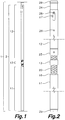
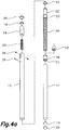
- the extendable prop 1 can be fitted between a floor and a parallel ceiling and comprises a plurality of tubular segments formed by a first tubular element 11 and a second tubular element 12, both being hollow and cylindrical, made of aluminum, and having the same inner and outer diameter.
- Their outer diameter is less than 6 cm, their wall is a few millimeters thick, and both the first and second tubular elements 11 and 12 have a length of about 110 cm, so the sum total does not exceed 220 cm.
- the length of the first and second tubular elements can be different from one another.
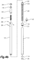
- Both first and second tubular elements 11 and 12 can be coupled to and uncoupled from one another in the longitudinal direction by means of a connecting element 22 as shown in Figure 3 , as a result of the attachment thereof the assembly forming a tubular element of the prop 2.
- the first tubular element 11 has at one of its ends a coupling thread 21 complementary with a threaded element 20.
- Said threaded element 20 is a hollow tube with one or more threads made on a portion of its outer face, which can be screwed onto and unscrewed from the female coupling thread 21 inserted and secured inside the end of the first tubular element 11.
- the threaded element 20 is thereby secured to the first tubular element 11 and can regulate the relative insertion and extraction thereof with respect to same by means of the threaded rotation thereof.
- the threaded element 20 can have a thread length of 60 cm, which would allow varying the total length of the extendable prop 1 about 45 cm by means of the mentioned regulation, and it can have holes in the perimeter thereof which allow inserting an extractable key that allows rotating the threaded element 20, exerting an angular force.
- the end of the threaded element 20 which is not inserted into the first tubular element 11 has a connecting element 22 integrated therewith which allows the attachment thereof with an end of the second tubular element 12, thereby attaching the first and second tubular elements 11 and 12.
- the connecting element 22 consists of a cylinder with an outer diameter equal to or less than the inner diameter of the second tubular element 12, such that it can be manually inserted therein in the longitudinal direction of the second tubular element 12.
- the connecting element consists of a coupling thread for coupling with the second tubular element 12 which would be provided with the corresponding coupling thread, for example, with a bushing 16 having a coupling thread, or a thread machined directly on the inner face of the second tubular element 12.
- first and second embodiments allow the threaded element 20 to be arranged in an intermediate position of the extendable prop 1, making it much more accessible to an operator, and making handling easier, but this element could obviously be arranged at one of the ends of the extendable prop 1.
- a maximum insertion limiter 23 performs a limiting function with the threaded element 20 and the connecting element 22, preventing part of the threaded element 20 from being inserted into the second tubular element 12.
- This maximum insertion limiter 23 is an intermediate portion of the element with an outer diameter equal to the outer diameter of the second tubular element 12, therefore making the insertion thereof impossible.
- the mentioned maximum insertion limiter 23 can in turn have holes in which a lever which aids the rotation of the threaded element 20 with respect to the first tubular element 11 in inserted, thereby regulating the insertion or extraction thereof, and thereby regulating the total height of the tubular element of the prop 2 as a result of the attachment of the first and second tubular elements 11 and 12.
- the second tubular element 12 has a movable element 24 partially inserted into one of its ends and attached thereto without preventing the movement of the second tubular element 12 in the longitudinal direction.
- This movable element 24 internally houses an elastic element 25 having an end secured to the second tubular element 12. This construction allows the movable element 24 to move in the longitudinal direction of the tubular element since it is subjected to a force, an elastic strength provided by the elastic element 25 resisting said movement.
- the movable element 24 is a tubular element of the prop 2 having an outer diameter smaller than the inner diameter of the second tubular element 12, with a closed end.
- a spring works as an elastic element 25, which spring has an end attached to the second tubular element 12 by means of a pin 26, for example.
- an indicator device 27 allows knowing the strain exerted by the spring, by means of, for example, a ruler measuring relative movement between the movable element 24 and the second tubular element 12, which allows knowing the strain of the elastic element 25 by means of Hooke's Law.
- the indicator device 27 is a screw 28 inserted perpendicularly in the tubular wall of the movable element 24, in the fraction of said movable element 24 inserted into the second tubular element 12, the head of said screw 28 projecting from the movable element 24, and preferably flush with the outer face of the second tubular element 12. Said head is fitted inside a longitudinal slot made on the cylindrical wall of the end of the second tubular element 12.
- Said head of the screw 28 thereby acts as a retainer of the movable element 24, preventing it from coming out of the second tubular element 12, while at the same time allowing its movement along the slot, and at the same time allowing an operator to see the position of the movable element 24 through the position of the head of the screw 28, also acting as an indicator device 27.
- the end of the movable element 24 is provided with an element having a high coefficient of friction 29 making it difficult for a force perpendicular to the extendable prop 1 to move it out of place since said extendable prop 1 is fitted against the ceiling and the floor by pressure.
- Said element having a high coefficient of friction 29 can be assembled on a panel attached by means of a shaft with bearings to the end of a tubular element 11 or 12, or to the end of a movable element 24, or to the end of a threaded element 20, or a joint made of a material with a low coefficient of friction, such as Teflon, can be used to make rotation thereof easier.
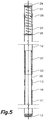
- one or more third tubular elements 13 having a short length, provided with a coupling thread can be arranged in the threaded segment of the threaded element 20 that is not housed inside the first tubular element 11.
- the longitudinal position of said third tubular element 13 on said segment can be regulated by means of the coupling thread. This allows it to be used for locking the position of the threaded element, tightening said third tubular element against the first tubular element 11 through the bushing 16 having a coupling thread, thereby locking the coupling thread, or allowing it to be located in any longitudinal position of said threaded element to serve as support for a possible securing device.
- the extendable prop 1 of this embodiment has no element projecting from the plane formed by the outer cylindrical wall of the tubular element.
- a plurality of those extendable props 1 can optionally be placed parallel to and equidistant from one another to subsequently support cladding made up of panels removably secured to said extendable props 1 through one or both faces by means of securing devices.
- the combination of the extendable prop 1, the securing device and the cladding panels provide a partition system which allows erecting partitions in a simple, clean and removable manner, allowing them to be reused in a different place, and the packaging of the entire system being in a small and easy-to-transport packet.
- a alternative embodiment in which the plurality of tubular segments includes, in addition to the first and second tubular elements 11 and 12, additional tubular elements having the same features which can be connected to said first and second tubular elements 11 and 12 by means of additional connecting elements 22, thereby increasing the total maximum length of the extendable prop, is also contemplated.
- the prop includes a securing device 30 consisting of a clamp 31 formed by a first arm 32 and a second arm 33 arranged opposite one another, which are attached at their proximal end to a support 34 from which they project almost perpendicularly.
- the distal ends of both arms 32 and 33 are arranged opposite and spaced from one another, the distance of separation thereof being smaller than a width of a tubular element 2, the tubular element being an elongated element having a constant section along a longitudinal axis E, and being in this embodiment an extendable prop having a circular section that can be fitted between a floor and a ceiling.
- Said distance of separation together with the capacity of the arms of being elastically deformable, allows said clamp 31 to be coupled to and uncoupled from the tubular element 2 by exerting a force perpendicular to the longitudinal axis E, causing said elastic deformation of the arms, being attached to the tubular element 2 as shown in Figure 7 after the coupling thereof.
- said support 34 has coupling means 35, including a main flange 36 provided with two main faces perpendicular to the longitudinal axis of the tubular element, an additional flange 38 symmetrical to the main flange 36 with respect to a plane of symmetry perpendicular to the longitudinal axis and two secondary flanges 37 each with two faces parallel to the longitudinal axis, said two secondary flanges 37 being symmetrical with respect to a plane parallel to the longitudinal axis.
- Said coupling means 35 allow securing cladding panels 40 to said tubular element by means of said securing device, the panels 40 being parallel to the mentioned longitudinal axis E.
- each main flange 36, additional flange 38 and secondary flange 37 has a rectangular section which is complementary with a corresponding main groove 46, additional groove 48 and secondary groove 47 made on the back of the cladding panels 40, as seen in Figure 6 .
- the flanges measure 3 mm wide and 4 mm high with respect to the support 34 and are arranged symmetrically with respect to a plane of symmetry perpendicular to the longitudinal axis E, the securing device 30 being coupled to the tubular element 2.
- grooves 46, 47 and 48 are made on areas close to the corners of the panels 40, four corners of four different panels 40 can be anchored on one and the same securing device 30 by means of inserting said flanges 36, 37 and 38 into said grooves 46, 47 and 48, which allows securing said four panels 40 in a laterally adjacent and coplanar position.
- a securing device 30 in each of the corners of each panel 40, cladding can be extended in all directions, while at the same time securing each of the panels 40.
- operable retainers 50 attached in a pivotable manner on the rear face of the panels have been envisaged, such that after coupling the panel to the securing device, the operation of said operable retainers 50 presses on and retains the coupling means 35 in the grooves envisaged on the rear face of the panel 40, as shown in Figure 7 .
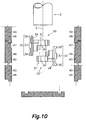
- adjacent panels are laterally coupled by means of a tongue and groove configuration or a stepped configuration, as seen in Figure 10 .
- the proposed securing device 30 also includes joining means 39 which in the embodiment shown in Figures 6 and 7 consist of two joining means arranged in each of the first and second arms 32 and 33, there being four joining means in total.
- each arm a joining means 39 in the form of a projection and a joining means 39 complementary to said projecting shape; in the example shown, the projecting shape is a cylindrical or frustoconical lug, and the complementary shape is a cylindrical or frustoconical cavity.
- joining means 39 allow both devices to be mutually coupled by means of the mutual coupling of their corresponding joining means 39 and 39'.
- respective clamps 31 and 31' must be superimposed or juxtaposed, arranging the distal end of the first and second arms 32' and 33' of the other laterally adjacent securing device 30' on the proximal end of the first and second arms 32 and 33 of the initial securing device 30, and also arranging the proximal end of said arms of the other laterally adjacent securing device 30' on the distal end of the arms of the initial securing device 30.
- the arms and the joining means 39 and 39' of the two securing devices 30 and 30' are aligned, while at the same time respective supports 34 are arranged on opposite sides and the coupling means 35 are oriented towards opposite sides, securing the panels 40 parallel to one another on opposite sides of the tubular element 2 to which the mentioned securing devices 30 and 30' are secured.
- the alignment of the joining means 39 and 39' of the two securing devices 30 and 30' allows their mutual coupling by means of inserting cylindrical lugs into cylindrical cavities in the example herein illustrated.
- the joining means 39 of the first arm 32 of the securing device 30 are coupled to the joining means 39' of the first arm 32' of the other securing device 30', and the joining means of the second arm 33 are coupled to the joining means of the other second arm 33'. That is only possible if the position of the other securing device 30' is inverted with respect to the position of the initial securing device 30.
- the cylindrical lugs are inserted into the cylindrical cavities in a direction parallel to the longitudinal axis E of the tubular element 2, the securing devices 30 and 30' being coupled to said tubular element 2, said direction of coupling being perpendicular to the direction of coupling of the securing devices 30 and 30' to the tubular element 2.
Landscapes
- Engineering & Computer Science (AREA)
- Architecture (AREA)
- Civil Engineering (AREA)
- Structural Engineering (AREA)
- Physics & Mathematics (AREA)
- Electromagnetism (AREA)
- Mechanical Engineering (AREA)
- Mutual Connection Of Rods And Tubes (AREA)
Claims (15)
- Kit zum Stellen von Wänden beinhaltend:• eine Vielzahl von ausziehbaren Stützen (1), welche gegen zwei parallelen Ebenen angebracht werden können, wobei jede Stütze (1) Folgendes umfasst:o mindestens ein hohles rohrförmiges Element (2), welches mit einem oberen Ende und einem unteren Ende versehen ist, welche eine Längsrichtung definieren, wobei das hohle rohrförmige Element (2) aus einer Vielzahl von rohrförmigen Segmenten mit einem äußeren Querschnitt mit der gleichen Größe gebildet ist, welche koaxial und zueinander fluchtend angeordnet sind, wobei die genannten rohrförmigen Segmente in der Lage sind, mittels mindestens eines Anschlusselementes (22) befestigt zu werden, und wobei jedes eine Länge aufweist, welche kleiner als drei Viertel der Gesamtlänge der ausziehbaren Stütze (1) in der ausgezogenen Stellung ist;o mindestens ein Gewindeelement (20), welches teilweise innerhalb des erwähnten rohrförmigen Elementes (2) aufgenommen ist, welches mittels eines Kopplungsgewindes (21) am rohrförmigen Element (2) befestigt ist, so dass eine einstellbare Einfügung und/oder Entnahme des genannten Gewindeelementes (20) in Bezug auf das genannte rohrförmige Element (2) bereitgestellt wird, wodurch die Gesamtlänge der ausziehbaren Stütze (1) erhöht oder verringert wird, wobei das erwähnte Kopplungsgewinde (21) das Gewindeelement (20) mit einem Ende eines der genannten rohrförmigen Segmente verbindet;o mindestens ein zusammendrückbares elastisches Element (25), welches in der Lage ist, die Gesamtlänge der ausziehbaren Stütze (1) zu verringern, da die genannte ausziehbare Stütze (1) einer axialen Zusammendrückung in Längsrichtung unterzogen wird, wobei das genannte elastische Element (25) an einem beweglichen Element (24) angeschlossen wird, welches sich in der axialen Längsrichtung des rohrförmigen Elementes (2) bewegt, wobei ein elastischer Widerstand gegen die genannte Bewegung geleistet wird;o mindestens eine Anzeigevorrichtung (27), welche die Menge von elastischer Kraft, welche vom genannten elastischen Element (25) ausgeübt wird, anzeigt, wenn es einer Zusammendrückung unterzogen wird;• eine Vielzahl von Fixierungsvorrichtungen (30, 30') zum lösbaren Fixieren von Verkleidungsplatten (40) an ausziehbaren Stützen (1);• eine Vielzahl von Verkleidungsplatten (40), welche mit den genannten Fixierungsvorrichtungen (30) gekoppelt werden können;dadurch gekennzeichnet, dass die genannte Fixierungsvorrichtung (30) zum lösbaren Fixieren von Verkleidungsplatten (40) an rohrförmigen Elementen (2) Folgendes umfasst:• eine Klemme (31), welche einen ersten Arm (32) und einen zweiten Arm (33) aufweist, welche elastisch verformbar und einander gegenüberliegend angeordnet sind, wobei beide Arme (32 und 33) mit einem proximalen Ende und einem distalen Ende versehen sind, wobei die proximalen Enden des ersten und des zweiten Armes (32 und 33) an einer Halterung (34) befestigt sind, und wobei die distalen Enden des ersten und des zweiten Armes (32 und 33) gegenüberliegend und voneinander beabstandet angeordnet sind, wobei der genannte Abstand kleiner als eine Breitenmessung eines rohrförmigen Elementes (2) ist, und wobei die Klemme (31) in der Lage ist, mittels elastischer Verformung des genannten ersten und zweites Armes (32, 33) unter Druck mit dem genannten rohrförmigen Element (2) gekoppelt und davon entkoppelt zu werden;• mindestens ein Kopplungsmittel (35), welches in der genannten Halterung (34) angeordnet ist, an welchem mindestens eine Verkleidungsplatte (40) lösbar fixiert werden kann; und wobei das rohrförmige Element (2) ein lineares Element ist, welches in die Richtung einer Längsachse (E) langgestreckt ist; und• mindestens ein Fügungsmittel (39), welches in mindestens einem des ersten und des zweiten Armes (32, 33) angeordnet ist, wobei das genannte Fügungsmittel (39) in der Lage ist, mit einem anderen Fügungsmittel (39') einer anderen Fixierungsvorrichtung (30'), welche komplementär zur Fixierungsvorrichtung (30) ist, gekoppelt zu werden, wobei die genannte andere Fixierungsvorrichtung (30') ein anderes Fügungsmittel (39'), eine andere Halterung (34') und ein anderes Kopplungsmittel (35') beinhaltet, wobei die gekoppelte Baugruppe aus beiden Fixierungsvorrichtungen (30, 30') ein eng anliegendes Gehäuse um das rohrförmige Element (2) herum bildet.
- Kit nach Anspruch 1, wobei die genannte andere Fixierungsvorrichtung (30') identisch mit der anfänglich beschriebenen Fixierungsvorrichtung (30) ist und einen ersten Arm und einen zweiten Arm (32', 33') beinhaltet, und wobei die genannte Fixierungsvorrichtung (30) mit einer anderen Fixierungsvorrichtung (30') gekoppelt ist, wobei der proximale Teil des ersten und des zweiten Armes (32, 33) der Fixierungsvorrichtung (30) in Bezug auf den distalen Teil des ersten und des zweiten Armes (32', 33') der anderen Fixierungsvorrichtung (30') nebeneinandergestellt sind.
- Kit nach Anspruch 1 oder 2, wobei die Richtung der Kopplung und Entkopplung des Fügungsmittels (39) der Fixierungsvorrichtung (30) in Bezug auf das Fügungsmittel (39') der anderen Fixierungsvorrichtung (30') etwa parallel zur Längsachse (E) des rohrförmigen Elementes (2) ist, wobei die Klemme (31) mit dem genannten rohrförmigen Element (2) gekoppelt ist.
- Kit nach einem der vorhergehenden Ansprüche 1 bis 3, wobei:• das Kopplungsmittel (35) der Halterung (34) eine Ausbildung aufweist, welche die gleichzeitige Kopplung von mindestens zwei seitlich benachbarten und komplanaren Platten (40) erlaubt, wobei das Kopplungsmittel (35) in Bezug auf eine vertikale, parallele und übereinstimmende Symmetrieebene in Bezug auf die Längsachse (E) symmetrisch ist, wobei die Klemme (31) in einer Kopplungsposition ist.
- Kit nach Anspruch 4, wobei:• mit der Fixierungsvorrichtung (30) mit der anderen Fixierungsvorrichtung (30') gekoppelt, die erwähnte horizontale Symmetrieebene des Kopplungsmittels (35) der Halterung (34) komplanar mit einer anderen horizontalen Symmetrieebene des anderen Kopplungsmittels (35') der anderen Halterung (34') der anderen Fixierungsvorrichtung (30') ist; und/oder• das Kopplungsmittel (35) einen horizontal langgestreckten Hauptflansch (36) beinhaltet, welcher einen konstanten Querschnitt aufweist, welcher mit zwei Hauptflächen senkrecht zur Längsachse (E) in der Kopplungsposition versehen ist, wobei der genannte Hauptflansch (36) komplementär zu einer Hauptnut (46) ist, welche auf der hinteren Fläche der Platten (40) hergestellt ist, wobei der Hauptflansch (36) wahlweise 3 mm in der Breite misst und 4 mm aus der Halterung (34) hervorsteht.
- Kit nach Anspruch 5, wobei das Kopplungsmittel (35) zusätzlich Folgendes beinhaltet:• zwei vertikal langgestreckte sekundäre Flansche (37), welche jeweils mit zwei Flächen parallel zur Längsachse (E) in der Kopplungsposition versehen sind, wobei die genannten zwei sekundären Flansche (37) komplementär zu zwei sekundären Nuten (47) sind, welche auf den hinteren Flächen der Platten (40) hergestellt sind; und• einen horizontal langgestreckten zusätzlichen Flansch (38), welcher mit zwei Flächen senkrecht zur Längsachse (E) in der Kopplungsposition versehen ist, wobei der genannte zusätzliche Flansch (38) komplementär zu einer zusätzlichen Nut (48) ist, welche auf der hinteren Fläche der Platten (40) hergestellt ist;wobei die sekundären Flansche (37) und/oder der zusätzliche Flansch (38) wahlweise 3 mm in der Breite messen und 4 mm aus der Halterung (34) hervorstehen.
- Kit nach einem der vorhergehenden Ansprüche 1 bis 6, wobei die Fixierungsvorrichtungen (30) eines oder mehrere der folgenden Merkmale beinhalten:• jeder erste Arm (32) und zweite Arm (33) besteht aus zwei Fügungsmitteln (39), wobei ein erstes Fügungsmittel in einer weiter proximalen Position der Halterung (34) angeordnet ist und ein zweites Fügungsmittel in einer weiter distalen Position als das erste Fügungsmittel angeordnet ist, wobei das erste und zweite Fügungsmittel komplementäre Kopplungsgeometrien aufweisen;• die Kopplungsmittel (35) der Halterung (34) derart ausgebildet sind, dass die am genannten Kopplungsmittel (35) fixierten Platten (40) in einer zur Längsachse (E) parallelen Ebene angeordnet sind, wobei die Klemme (31) im rohrförmigen Element (2) verankert ist.
- Kit nach Anspruch 1, wobei die genannten Verkleidungsplatten (40) starre rechteckige Platten sind, welche jeweils mit einer rechteckigen Stirnfläche versehen sind, welche von einer oberen Randfläche, einer unteren Randfläche und zwei seitlichen Randflächen begrenzt ist, welche wiederum eine rechteckige hintere Fläche parallel zur genannten Stirnfläche begrenzen, wobei jede Platte auf deren hinteren Fläche Folgendes beinhaltet:• Befestigungsausbildungen, komplementär zu, und vorgesehen zur Kopplung mit, den Kopplungsmitteln der Fixierungsvorrichtungen in Kombination mit bedienbaren Arretierungen (50), welche dazu vorgesehen sind, die Kopplungsmittel (35) in den Befestigungsausbildungen der Platten (40) zu arretieren, wobei sie in einer Arretierungsposition sind; und/oder• Befestigungsausbildungen, komplementär zu, und vorgesehen zur Kopplung mit, den Kopplungsmitteln der Fixierungsvorrichtungen bestehend aus Nuten komplementär zu den Kopplungsmitteln (35) der Fixierungsvorrichtungen (30), welche aus Flanschen bestehen, wobei die Flansche und Nuten bemessen sind, um eine eng anliegende Einfügung, oder eine Einfügung mit einem bestimmten spezifischen Spiel zu erreichen; und/oder• die genannten Platten auf deren seitlich benachbarten und/oder übereinanderliegenden Randflächen ein Feder- und Nutkopplungsmittel aufweisen, welches auf deren gegenseitig einander gegenüberliegenden Flächen angeordnet vorgesehen ist.
- Kit nach einem vorhergehenden Anspruch, wobei das genannte, in jeder Stütze (1) beinhaltete, bewegliche Element (24) eines oder mehrere der folgenden Merkmale beinhaltet:• es ist mit einem Ende eines der genannten rohrförmigen Segmente verbu nden;• es ist mit dem Gewindeelement (20) integriert;• es ist mit dem Anschlusselement (22) integriert.
- Kit nach einem vorhergehenden Anspruch, wobei ein Element, welches einen hohen Reibungskoeffizienten (29) aufweist, mit einem Ende eines rohrförmigen Segmentes verbunden ist, und ein anderes Element, welches einen hohen Reibungskoeffizienten (29) aufweist, mit einem Ende eines anderen rohrförmigen Segmentes verbunden ist.
- Kit nach Anspruch 10, wobei die genannte Verbindung des Elementes, welches einen hohen Reibungskoeffizienten (29) aufweist, mit dem Ende eines rohrförmigen Segmentes mittels Folgenden hergestellt wird:• einer rotierenden Befestigung (14), welche eine relative Rotation in Bezug auf die axiale Achse des Elementes, welches einen hohen Reibungskoeffizienten (29) in Bezug auf das rohrförmige Segment aufweist, erlaubt; oder• einer rotierenden Befestigung (14), welche eine relative Rotation in Bezug auf die axiale Achse des Elementes, welches einen hohen Reibungskoeffizienten (29) in Bezug auf das rohrförmige Segment aufweist, erlaubt und welche einen Gewinderegler integriert, welcher die relative axiale Längsbewegung zwischen dem Element, welches einen hohen Reibungskoeffizienten (29) aufweist, und dem rohrförmigen Segment, mittels Einschraubens oder Losschraubens des genannten Gewindereglers erlaubt.
- Kit nach Anspruch 10 oder 11, wobei mindestens eines der Elemente, welche einen hohen Reibungskoeffizienten (29) aufweisen, mit dem Gewindeelement (20) oder dem beweglichen Element (24) integriert ist.
- Kit nach einem der vorhergehenden Ansprüche, wobei die genannte Anzeigevorrichtung (27) ein Lineal ist, welches das Messen einer relativen Bewegung zwischen dem beweglichen Element (24) und dem rohrförmigen Segment, in welchem es aufgenommen ist, erlaubt.
- Kit nach einem vorhergehenden Anspruch, wobei die Vielzahl von rohrförmigen Segmenten ein erstes rohrförmiges Element (11) und ein zweites rohrförmiges Element (12) sind.
- Kit nach einem der vorhergehenden Ansprüche, wobei jede Stütze (1) auch eines oder mehrere der folgenden Merkmale beinhaltet:• die rohrförmigen Segmente sind zylindrisch;• das genannte Anschlusselement (22) ist mit dem Gewindeelement (20) integriert;• kein Element der ausziehbaren Stütze (1) steht aus der Ebene hervor, welche vom Außenumfang der rohrförmigen Segmente definiert wird;• mindestens ein drittes rohrförmiges Element (13), welches mit einem Kopplungsgewinde versehen ist, ist mit einem Zwischenteil des Gewindeelementes (20) gekoppelt, nicht in einem der rohrförmigen Segmente eingefügt, und das genannte mindestens dritte rohrförmige Element (13) bewegt sich in Längsrichtung des Gewindeelementes (20) mittels des Betriebs, welcher von der gewindeartigen Rotation des dritten rohrförmigen Elementes (13) verursacht wird;• das rohrförmige Element (2) der Stütze weist querlaufende Durchgangsbohrungen auf;• der genannte maximale Einfügungsbegrenzer (23) ist ein mittiger Teil, welcher zwischen dem Anschlusselement (20) und dem Gewindeelement (22) angeordnet ist, wobei der maximale Einfügungsbegrenzer (23) einen größeren äußeren Querschnitt als der innere Hohlraum der anzuschließenden rohrförmigen Elemente aufweist.
Applications Claiming Priority (3)
| Application Number | Priority Date | Filing Date | Title |
|---|---|---|---|
| ES201430588U ES1117832Y (es) | 2014-04-30 | 2014-04-30 | Puntal extensible atracable entre dos planos paralelos |
| ES201530186U ES1137457Y (es) | 2015-02-17 | 2015-02-17 | Dispositivo de fijacion amovible de placas de revestimiento sobre elementos tubulares |
| PCT/ES2015/000057 WO2015166119A1 (es) | 2014-04-30 | 2015-04-29 | Puntal extensible atracable entre dos planos paralelos y kit para erección de paredes |
Publications (3)
| Publication Number | Publication Date |
|---|---|
| EP3138975A1 EP3138975A1 (de) | 2017-03-08 |
| EP3138975A4 EP3138975A4 (de) | 2018-01-31 |
| EP3138975B1 true EP3138975B1 (de) | 2019-06-12 |
Family
ID=54358210
Family Applications (1)
| Application Number | Title | Priority Date | Filing Date |
|---|---|---|---|
| EP15785791.3A Active EP3138975B1 (de) | 2014-04-30 | 2015-04-29 | Kit zum stellen von wänden |
Country Status (3)
| Country | Link |
|---|---|
| EP (1) | EP3138975B1 (de) |
| ES (1) | ES2740698T3 (de) |
| WO (1) | WO2015166119A1 (de) |
Families Citing this family (3)
| Publication number | Priority date | Publication date | Assignee | Title |
|---|---|---|---|---|
| CN113062501B (zh) * | 2021-04-28 | 2024-09-17 | 李莉 | 一种室内空间分割用隔板组件 |
| CN116517148B (zh) * | 2023-05-19 | 2026-03-24 | 河北惠驰新材料科技有限公司 | 一种墙体装配模块 |
| CN117627227B (zh) * | 2024-01-26 | 2024-04-23 | 山西陆华装饰材料有限公司 | 一种装配式隔断及其制作方法 |
Family Cites Families (11)
| Publication number | Priority date | Publication date | Assignee | Title |
|---|---|---|---|---|
| FR429863A (fr) * | 1911-04-28 | 1911-10-03 | Pierre Theophile Guenardeau | Baton ou portant à coulisses |
| US2770886A (en) * | 1953-10-23 | 1956-11-20 | Bruce W Johnson | Ridge board holder |
| US2855037A (en) * | 1956-01-30 | 1958-10-07 | Theophile A Stiffel | Portable wall or panel structures and means for supporting same |
| US3349528A (en) * | 1966-06-17 | 1967-10-31 | John A Salt | Portable partition with telescoping tube support |
| US3686810A (en) * | 1970-11-05 | 1972-08-29 | Charles R Allen | Snap on drywall fastening system |
| US5088672A (en) * | 1991-01-02 | 1992-02-18 | Neuendorf Paul A | Circumscribing sign clamp and method of fabrication |
| FR2712064A1 (fr) * | 1993-11-05 | 1995-05-12 | Performance Sa | Dispositif à colonne de mise en place d'objets dans un espace sous plafond. |
| DE4402327C2 (de) * | 1994-01-27 | 2002-04-04 | Joachim Kuhn | Bausatz für Kleinmöbel |
| US5826847A (en) * | 1997-06-30 | 1998-10-27 | Warner; Stanley H. | Telescoping pole with quick length adjustment |
| NL1017028C2 (nl) * | 2001-01-03 | 2002-07-16 | Tinga Res & Dev B V | Klem voor het bevestigen van een paneel, zoals een wandpaneel voor een presentatiestand, aan een steun, zoals een paal. |
| CA2739414C (en) * | 2011-05-06 | 2018-05-22 | Athos Construction Products, Inc. | Telescopic safety post |
-
2015
- 2015-04-29 ES ES15785791T patent/ES2740698T3/es active Active
- 2015-04-29 EP EP15785791.3A patent/EP3138975B1/de active Active
- 2015-04-29 WO PCT/ES2015/000057 patent/WO2015166119A1/es not_active Ceased
Non-Patent Citations (1)
| Title |
|---|
| None * |
Also Published As
| Publication number | Publication date |
|---|---|
| ES2740698T3 (es) | 2020-02-06 |
| EP3138975A1 (de) | 2017-03-08 |
| WO2015166119A1 (es) | 2015-11-05 |
| EP3138975A4 (de) | 2018-01-31 |
Similar Documents
| Publication | Publication Date | Title |
|---|---|---|
| US10244864B2 (en) | Device and system for joining objects | |
| US9376812B2 (en) | Ceiling panel mounting system | |
| EP2852720B1 (de) | Bausatz und befestigungssystem für belüftete verkleidungen | |
| EP2766616B1 (de) | Mechanisch ineinandergreifende rahmenkonstruktionen | |
| US9022712B2 (en) | Fastener for attaching objects to channeled members | |
| US8453412B2 (en) | Spring bolt hanger | |
| EP3138975B1 (de) | Kit zum stellen von wänden | |
| US11105365B2 (en) | Fixation system | |
| US9366022B2 (en) | In-line frame connector assembly and system for large portable frameworks | |
| CA2919119A1 (en) | Self-locking mechanism and paneling | |
| NZ742531A (en) | Float, float assemblies, float adapters and interfaces, float vibration apparatus, and groovers and methods | |
| GB2453012A (en) | Construction profile and support system | |
| JP6954543B2 (ja) | 建築スラブ用インサート | |
| US11976461B2 (en) | Snap joint and method of use | |
| KR20170038885A (ko) | 로드형 프로파일 요소를 위한 코너 커넥터 | |
| ITBZ20080025A1 (it) | Sistema consistente in profilati ed elementi di giunzione per la realizzazione di strutture portanti | |
| CA2871062A1 (en) | Connection means for coupling two components | |
| US20210197328A1 (en) | Structural profile | |
| EP2425748B1 (de) | Modulares Kit zur maßgeschneiderten Herstellung von Wagen, Arbeitsplätzen, Lagereinheiten und ähnlichen Strukturen | |
| US20160138625A1 (en) | Fitting for strut channel | |
| KR102517181B1 (ko) | 랙 | |
| US10079482B2 (en) | Outlet box for vertical or horizontal mounting | |
| EP2117093A1 (de) | Befestigungssystem für eine Halteklemme eines Kabelträgersystems mit einer Gewindestange, die an einer Decke verankert werden kann | |
| WO2023150858A1 (en) | Snap joint and method of use | |
| WO2020222016A1 (en) | A fixing device for securing an item to a wall |
Legal Events
| Date | Code | Title | Description |
|---|---|---|---|
| STAA | Information on the status of an ep patent application or granted ep patent |
Free format text: STATUS: THE INTERNATIONAL PUBLICATION HAS BEEN MADE |
|
| PUAI | Public reference made under article 153(3) epc to a published international application that has entered the european phase |
Free format text: ORIGINAL CODE: 0009012 |
|
| STAA | Information on the status of an ep patent application or granted ep patent |
Free format text: STATUS: REQUEST FOR EXAMINATION WAS MADE |
|
| 17P | Request for examination filed |
Effective date: 20161020 |
|
| AK | Designated contracting states |
Kind code of ref document: A1 Designated state(s): AL AT BE BG CH CY CZ DE DK EE ES FI FR GB GR HR HU IE IS IT LI LT LU LV MC MK MT NL NO PL PT RO RS SE SI SK SM TR |
|
| AX | Request for extension of the european patent |
Extension state: BA ME |
|
| DAV | Request for validation of the european patent (deleted) | ||
| DAX | Request for extension of the european patent (deleted) | ||
| A4 | Supplementary search report drawn up and despatched |
Effective date: 20180105 |
|
| RIC1 | Information provided on ipc code assigned before grant |
Ipc: E04B 2/82 20060101ALI20171222BHEP Ipc: E04G 21/24 20060101ALI20171222BHEP Ipc: E04F 13/24 20060101ALI20171222BHEP Ipc: E04B 2/74 20060101AFI20171222BHEP |
|
| GRAP | Despatch of communication of intention to grant a patent |
Free format text: ORIGINAL CODE: EPIDOSNIGR1 |
|
| STAA | Information on the status of an ep patent application or granted ep patent |
Free format text: STATUS: GRANT OF PATENT IS INTENDED |
|
| INTG | Intention to grant announced |
Effective date: 20181206 |
|
| GRAS | Grant fee paid |
Free format text: ORIGINAL CODE: EPIDOSNIGR3 |
|
| GRAA | (expected) grant |
Free format text: ORIGINAL CODE: 0009210 |
|
| STAA | Information on the status of an ep patent application or granted ep patent |
Free format text: STATUS: THE PATENT HAS BEEN GRANTED |
|
| AK | Designated contracting states |
Kind code of ref document: B1 Designated state(s): AL AT BE BG CH CY CZ DE DK EE ES FI FR GB GR HR HU IE IS IT LI LT LU LV MC MK MT NL NO PL PT RO RS SE SI SK SM TR |
|
| REG | Reference to a national code |
Ref country code: GB Ref legal event code: FG4D |
|
| REG | Reference to a national code |
Ref country code: CH Ref legal event code: EP |
|
| REG | Reference to a national code |
Ref country code: AT Ref legal event code: REF Ref document number: 1142711 Country of ref document: AT Kind code of ref document: T Effective date: 20190615 |
|
| REG | Reference to a national code |
Ref country code: DE Ref legal event code: R096 Ref document number: 602015031911 Country of ref document: DE |
|
| REG | Reference to a national code |
Ref country code: IE Ref legal event code: FG4D |
|
| REG | Reference to a national code |
Ref country code: NL Ref legal event code: MP Effective date: 20190612 |
|
| REG | Reference to a national code |
Ref country code: LT Ref legal event code: MG4D |
|
| PG25 | Lapsed in a contracting state [announced via postgrant information from national office to epo] |
Ref country code: FI Free format text: LAPSE BECAUSE OF FAILURE TO SUBMIT A TRANSLATION OF THE DESCRIPTION OR TO PAY THE FEE WITHIN THE PRESCRIBED TIME-LIMIT Effective date: 20190612 Ref country code: AL Free format text: LAPSE BECAUSE OF FAILURE TO SUBMIT A TRANSLATION OF THE DESCRIPTION OR TO PAY THE FEE WITHIN THE PRESCRIBED TIME-LIMIT Effective date: 20190612 Ref country code: NO Free format text: LAPSE BECAUSE OF FAILURE TO SUBMIT A TRANSLATION OF THE DESCRIPTION OR TO PAY THE FEE WITHIN THE PRESCRIBED TIME-LIMIT Effective date: 20190912 Ref country code: SE Free format text: LAPSE BECAUSE OF FAILURE TO SUBMIT A TRANSLATION OF THE DESCRIPTION OR TO PAY THE FEE WITHIN THE PRESCRIBED TIME-LIMIT Effective date: 20190612 Ref country code: HR Free format text: LAPSE BECAUSE OF FAILURE TO SUBMIT A TRANSLATION OF THE DESCRIPTION OR TO PAY THE FEE WITHIN THE PRESCRIBED TIME-LIMIT Effective date: 20190612 Ref country code: LT Free format text: LAPSE BECAUSE OF FAILURE TO SUBMIT A TRANSLATION OF THE DESCRIPTION OR TO PAY THE FEE WITHIN THE PRESCRIBED TIME-LIMIT Effective date: 20190612 |
|
| PG25 | Lapsed in a contracting state [announced via postgrant information from national office to epo] |
Ref country code: LV Free format text: LAPSE BECAUSE OF FAILURE TO SUBMIT A TRANSLATION OF THE DESCRIPTION OR TO PAY THE FEE WITHIN THE PRESCRIBED TIME-LIMIT Effective date: 20190612 Ref country code: RS Free format text: LAPSE BECAUSE OF FAILURE TO SUBMIT A TRANSLATION OF THE DESCRIPTION OR TO PAY THE FEE WITHIN THE PRESCRIBED TIME-LIMIT Effective date: 20190612 Ref country code: BG Free format text: LAPSE BECAUSE OF FAILURE TO SUBMIT A TRANSLATION OF THE DESCRIPTION OR TO PAY THE FEE WITHIN THE PRESCRIBED TIME-LIMIT Effective date: 20190912 Ref country code: GR Free format text: LAPSE BECAUSE OF FAILURE TO SUBMIT A TRANSLATION OF THE DESCRIPTION OR TO PAY THE FEE WITHIN THE PRESCRIBED TIME-LIMIT Effective date: 20190913 |
|
| REG | Reference to a national code |
Ref country code: AT Ref legal event code: MK05 Ref document number: 1142711 Country of ref document: AT Kind code of ref document: T Effective date: 20190612 |
|
| PG25 | Lapsed in a contracting state [announced via postgrant information from national office to epo] |
Ref country code: CZ Free format text: LAPSE BECAUSE OF FAILURE TO SUBMIT A TRANSLATION OF THE DESCRIPTION OR TO PAY THE FEE WITHIN THE PRESCRIBED TIME-LIMIT Effective date: 20190612 Ref country code: RO Free format text: LAPSE BECAUSE OF FAILURE TO SUBMIT A TRANSLATION OF THE DESCRIPTION OR TO PAY THE FEE WITHIN THE PRESCRIBED TIME-LIMIT Effective date: 20190612 Ref country code: SK Free format text: LAPSE BECAUSE OF FAILURE TO SUBMIT A TRANSLATION OF THE DESCRIPTION OR TO PAY THE FEE WITHIN THE PRESCRIBED TIME-LIMIT Effective date: 20190612 Ref country code: AT Free format text: LAPSE BECAUSE OF FAILURE TO SUBMIT A TRANSLATION OF THE DESCRIPTION OR TO PAY THE FEE WITHIN THE PRESCRIBED TIME-LIMIT Effective date: 20190612 Ref country code: NL Free format text: LAPSE BECAUSE OF FAILURE TO SUBMIT A TRANSLATION OF THE DESCRIPTION OR TO PAY THE FEE WITHIN THE PRESCRIBED TIME-LIMIT Effective date: 20190612 Ref country code: EE Free format text: LAPSE BECAUSE OF FAILURE TO SUBMIT A TRANSLATION OF THE DESCRIPTION OR TO PAY THE FEE WITHIN THE PRESCRIBED TIME-LIMIT Effective date: 20190612 Ref country code: PT Free format text: LAPSE BECAUSE OF FAILURE TO SUBMIT A TRANSLATION OF THE DESCRIPTION OR TO PAY THE FEE WITHIN THE PRESCRIBED TIME-LIMIT Effective date: 20191014 |
|
| REG | Reference to a national code |
Ref country code: ES Ref legal event code: FG2A Ref document number: 2740698 Country of ref document: ES Kind code of ref document: T3 Effective date: 20200206 |
|
| PG25 | Lapsed in a contracting state [announced via postgrant information from national office to epo] |
Ref country code: IT Free format text: LAPSE BECAUSE OF FAILURE TO SUBMIT A TRANSLATION OF THE DESCRIPTION OR TO PAY THE FEE WITHIN THE PRESCRIBED TIME-LIMIT Effective date: 20190612 Ref country code: IS Free format text: LAPSE BECAUSE OF FAILURE TO SUBMIT A TRANSLATION OF THE DESCRIPTION OR TO PAY THE FEE WITHIN THE PRESCRIBED TIME-LIMIT Effective date: 20191012 Ref country code: SM Free format text: LAPSE BECAUSE OF FAILURE TO SUBMIT A TRANSLATION OF THE DESCRIPTION OR TO PAY THE FEE WITHIN THE PRESCRIBED TIME-LIMIT Effective date: 20190612 |
|
| REG | Reference to a national code |
Ref country code: DE Ref legal event code: R097 Ref document number: 602015031911 Country of ref document: DE |
|
| PG25 | Lapsed in a contracting state [announced via postgrant information from national office to epo] |
Ref country code: TR Free format text: LAPSE BECAUSE OF FAILURE TO SUBMIT A TRANSLATION OF THE DESCRIPTION OR TO PAY THE FEE WITHIN THE PRESCRIBED TIME-LIMIT Effective date: 20190612 |
|
| PLBE | No opposition filed within time limit |
Free format text: ORIGINAL CODE: 0009261 |
|
| STAA | Information on the status of an ep patent application or granted ep patent |
Free format text: STATUS: NO OPPOSITION FILED WITHIN TIME LIMIT |
|
| PG25 | Lapsed in a contracting state [announced via postgrant information from national office to epo] |
Ref country code: DK Free format text: LAPSE BECAUSE OF FAILURE TO SUBMIT A TRANSLATION OF THE DESCRIPTION OR TO PAY THE FEE WITHIN THE PRESCRIBED TIME-LIMIT Effective date: 20190612 Ref country code: PL Free format text: LAPSE BECAUSE OF FAILURE TO SUBMIT A TRANSLATION OF THE DESCRIPTION OR TO PAY THE FEE WITHIN THE PRESCRIBED TIME-LIMIT Effective date: 20190612 |
|
| 26N | No opposition filed |
Effective date: 20200313 |
|
| PG25 | Lapsed in a contracting state [announced via postgrant information from national office to epo] |
Ref country code: SI Free format text: LAPSE BECAUSE OF FAILURE TO SUBMIT A TRANSLATION OF THE DESCRIPTION OR TO PAY THE FEE WITHIN THE PRESCRIBED TIME-LIMIT Effective date: 20190612 Ref country code: IS Free format text: LAPSE BECAUSE OF FAILURE TO SUBMIT A TRANSLATION OF THE DESCRIPTION OR TO PAY THE FEE WITHIN THE PRESCRIBED TIME-LIMIT Effective date: 20200224 |
|
| PG2D | Information on lapse in contracting state deleted |
Ref country code: IS |
|
| PG25 | Lapsed in a contracting state [announced via postgrant information from national office to epo] |
Ref country code: MC Free format text: LAPSE BECAUSE OF FAILURE TO SUBMIT A TRANSLATION OF THE DESCRIPTION OR TO PAY THE FEE WITHIN THE PRESCRIBED TIME-LIMIT Effective date: 20190612 |
|
| REG | Reference to a national code |
Ref country code: CH Ref legal event code: PL |
|
| PG25 | Lapsed in a contracting state [announced via postgrant information from national office to epo] |
Ref country code: LI Free format text: LAPSE BECAUSE OF NON-PAYMENT OF DUE FEES Effective date: 20200430 Ref country code: LU Free format text: LAPSE BECAUSE OF NON-PAYMENT OF DUE FEES Effective date: 20200429 Ref country code: CH Free format text: LAPSE BECAUSE OF NON-PAYMENT OF DUE FEES Effective date: 20200430 |
|
| REG | Reference to a national code |
Ref country code: BE Ref legal event code: MM Effective date: 20200430 |
|
| PG25 | Lapsed in a contracting state [announced via postgrant information from national office to epo] |
Ref country code: BE Free format text: LAPSE BECAUSE OF NON-PAYMENT OF DUE FEES Effective date: 20200430 |
|
| PG25 | Lapsed in a contracting state [announced via postgrant information from national office to epo] |
Ref country code: IE Free format text: LAPSE BECAUSE OF NON-PAYMENT OF DUE FEES Effective date: 20200429 |
|
| PG25 | Lapsed in a contracting state [announced via postgrant information from national office to epo] |
Ref country code: MT Free format text: LAPSE BECAUSE OF FAILURE TO SUBMIT A TRANSLATION OF THE DESCRIPTION OR TO PAY THE FEE WITHIN THE PRESCRIBED TIME-LIMIT Effective date: 20190612 Ref country code: CY Free format text: LAPSE BECAUSE OF FAILURE TO SUBMIT A TRANSLATION OF THE DESCRIPTION OR TO PAY THE FEE WITHIN THE PRESCRIBED TIME-LIMIT Effective date: 20190612 |
|
| PG25 | Lapsed in a contracting state [announced via postgrant information from national office to epo] |
Ref country code: MK Free format text: LAPSE BECAUSE OF FAILURE TO SUBMIT A TRANSLATION OF THE DESCRIPTION OR TO PAY THE FEE WITHIN THE PRESCRIBED TIME-LIMIT Effective date: 20190612 |
|
| P01 | Opt-out of the competence of the unified patent court (upc) registered |
Effective date: 20230322 |
|
| PGFP | Annual fee paid to national office [announced via postgrant information from national office to epo] |
Ref country code: DE Payment date: 20250528 Year of fee payment: 11 |
|
| PGFP | Annual fee paid to national office [announced via postgrant information from national office to epo] |
Ref country code: GB Payment date: 20250429 Year of fee payment: 11 Ref country code: ES Payment date: 20250523 Year of fee payment: 11 |
|
| PGFP | Annual fee paid to national office [announced via postgrant information from national office to epo] |
Ref country code: FR Payment date: 20250429 Year of fee payment: 11 |