EP3139070B1 - Steuerungsverfahren zum durchführen eines gangschaltvorgangs in einem doppelkupplungsgetriebe - Google Patents
Steuerungsverfahren zum durchführen eines gangschaltvorgangs in einem doppelkupplungsgetriebe Download PDFInfo
- Publication number
- EP3139070B1 EP3139070B1 EP16187106.6A EP16187106A EP3139070B1 EP 3139070 B1 EP3139070 B1 EP 3139070B1 EP 16187106 A EP16187106 A EP 16187106A EP 3139070 B1 EP3139070 B1 EP 3139070B1
- Authority
- EP
- European Patent Office
- Prior art keywords
- clutch
- gear
- torque
- engine
- speed
- Prior art date
- Legal status (The legal status is an assumption and is not a legal conclusion. Google has not performed a legal analysis and makes no representation as to the accuracy of the status listed.)
- Active
Links
Images




Classifications
-
- B—PERFORMING OPERATIONS; TRANSPORTING
- B60—VEHICLES IN GENERAL
- B60W—CONJOINT CONTROL OF VEHICLE SUB-UNITS OF DIFFERENT TYPE OR DIFFERENT FUNCTION; CONTROL SYSTEMS SPECIALLY ADAPTED FOR HYBRID VEHICLES; ROAD VEHICLE DRIVE CONTROL SYSTEMS FOR PURPOSES NOT RELATED TO THE CONTROL OF A PARTICULAR SUB-UNIT
- B60W30/00—Purposes of road vehicle drive control systems not related to the control of a particular sub-unit, e.g. of systems using conjoint control of vehicle sub-units
- B60W30/18—Propelling the vehicle
- B60W30/19—Improvement of gear change, e.g. by synchronisation or smoothing gear shift
-
- F—MECHANICAL ENGINEERING; LIGHTING; HEATING; WEAPONS; BLASTING
- F16—ENGINEERING ELEMENTS AND UNITS; GENERAL MEASURES FOR PRODUCING AND MAINTAINING EFFECTIVE FUNCTIONING OF MACHINES OR INSTALLATIONS; THERMAL INSULATION IN GENERAL
- F16H—GEARING
- F16H61/00—Control functions within control units of change-speed- or reversing-gearings for conveying rotary motion ; Control of exclusively fluid gearing, friction gearing, gearings with endless flexible members or other particular types of gearing
- F16H61/68—Control functions within control units of change-speed- or reversing-gearings for conveying rotary motion ; Control of exclusively fluid gearing, friction gearing, gearings with endless flexible members or other particular types of gearing specially adapted for stepped gearings
- F16H61/684—Control functions within control units of change-speed- or reversing-gearings for conveying rotary motion ; Control of exclusively fluid gearing, friction gearing, gearings with endless flexible members or other particular types of gearing specially adapted for stepped gearings without interruption of drive
- F16H61/688—Control functions within control units of change-speed- or reversing-gearings for conveying rotary motion ; Control of exclusively fluid gearing, friction gearing, gearings with endless flexible members or other particular types of gearing specially adapted for stepped gearings without interruption of drive with two inputs, e.g. selection of one of two torque-flow paths by clutches
-
- B—PERFORMING OPERATIONS; TRANSPORTING
- B60—VEHICLES IN GENERAL
- B60W—CONJOINT CONTROL OF VEHICLE SUB-UNITS OF DIFFERENT TYPE OR DIFFERENT FUNCTION; CONTROL SYSTEMS SPECIALLY ADAPTED FOR HYBRID VEHICLES; ROAD VEHICLE DRIVE CONTROL SYSTEMS FOR PURPOSES NOT RELATED TO THE CONTROL OF A PARTICULAR SUB-UNIT
- B60W10/00—Conjoint control of vehicle sub-units of different type or different function
- B60W10/02—Conjoint control of vehicle sub-units of different type or different function including control of driveline clutches
-
- B—PERFORMING OPERATIONS; TRANSPORTING
- B60—VEHICLES IN GENERAL
- B60W—CONJOINT CONTROL OF VEHICLE SUB-UNITS OF DIFFERENT TYPE OR DIFFERENT FUNCTION; CONTROL SYSTEMS SPECIALLY ADAPTED FOR HYBRID VEHICLES; ROAD VEHICLE DRIVE CONTROL SYSTEMS FOR PURPOSES NOT RELATED TO THE CONTROL OF A PARTICULAR SUB-UNIT
- B60W10/00—Conjoint control of vehicle sub-units of different type or different function
- B60W10/04—Conjoint control of vehicle sub-units of different type or different function including control of propulsion units
- B60W10/06—Conjoint control of vehicle sub-units of different type or different function including control of propulsion units including control of combustion engines
-
- B—PERFORMING OPERATIONS; TRANSPORTING
- B60—VEHICLES IN GENERAL
- B60W—CONJOINT CONTROL OF VEHICLE SUB-UNITS OF DIFFERENT TYPE OR DIFFERENT FUNCTION; CONTROL SYSTEMS SPECIALLY ADAPTED FOR HYBRID VEHICLES; ROAD VEHICLE DRIVE CONTROL SYSTEMS FOR PURPOSES NOT RELATED TO THE CONTROL OF A PARTICULAR SUB-UNIT
- B60W10/00—Conjoint control of vehicle sub-units of different type or different function
- B60W10/10—Conjoint control of vehicle sub-units of different type or different function including control of change-speed gearings
- B60W10/11—Stepped gearings
- B60W10/113—Stepped gearings with two input flow paths, e.g. double clutch transmission selection of one of the torque flow paths by the corresponding input clutch
-
- B—PERFORMING OPERATIONS; TRANSPORTING
- B60—VEHICLES IN GENERAL
- B60W—CONJOINT CONTROL OF VEHICLE SUB-UNITS OF DIFFERENT TYPE OR DIFFERENT FUNCTION; CONTROL SYSTEMS SPECIALLY ADAPTED FOR HYBRID VEHICLES; ROAD VEHICLE DRIVE CONTROL SYSTEMS FOR PURPOSES NOT RELATED TO THE CONTROL OF A PARTICULAR SUB-UNIT
- B60W30/00—Purposes of road vehicle drive control systems not related to the control of a particular sub-unit, e.g. of systems using conjoint control of vehicle sub-units
- B60W30/18—Propelling the vehicle
- B60W30/182—Selecting between different operative modes, e.g. comfort and performance modes
-
- F—MECHANICAL ENGINEERING; LIGHTING; HEATING; WEAPONS; BLASTING
- F16—ENGINEERING ELEMENTS AND UNITS; GENERAL MEASURES FOR PRODUCING AND MAINTAINING EFFECTIVE FUNCTIONING OF MACHINES OR INSTALLATIONS; THERMAL INSULATION IN GENERAL
- F16D—COUPLINGS FOR TRANSMITTING ROTATION; CLUTCHES; BRAKES
- F16D48/00—External control of clutches
- F16D48/06—Control by electric or electronic means, e.g. of fluid pressure
-
- F—MECHANICAL ENGINEERING; LIGHTING; HEATING; WEAPONS; BLASTING
- F16—ENGINEERING ELEMENTS AND UNITS; GENERAL MEASURES FOR PRODUCING AND MAINTAINING EFFECTIVE FUNCTIONING OF MACHINES OR INSTALLATIONS; THERMAL INSULATION IN GENERAL
- F16H—GEARING
- F16H61/00—Control functions within control units of change-speed- or reversing-gearings for conveying rotary motion ; Control of exclusively fluid gearing, friction gearing, gearings with endless flexible members or other particular types of gearing
- F16H61/02—Control functions within control units of change-speed- or reversing-gearings for conveying rotary motion ; Control of exclusively fluid gearing, friction gearing, gearings with endless flexible members or other particular types of gearing characterised by the signals used
- F16H61/0202—Control functions within control units of change-speed- or reversing-gearings for conveying rotary motion ; Control of exclusively fluid gearing, friction gearing, gearings with endless flexible members or other particular types of gearing characterised by the signals used the signals being electric
- F16H61/0204—Control functions within control units of change-speed- or reversing-gearings for conveying rotary motion ; Control of exclusively fluid gearing, friction gearing, gearings with endless flexible members or other particular types of gearing characterised by the signals used the signals being electric for gearshift control, e.g. control functions for performing shifting or generation of shift signal
-
- B—PERFORMING OPERATIONS; TRANSPORTING
- B60—VEHICLES IN GENERAL
- B60W—CONJOINT CONTROL OF VEHICLE SUB-UNITS OF DIFFERENT TYPE OR DIFFERENT FUNCTION; CONTROL SYSTEMS SPECIALLY ADAPTED FOR HYBRID VEHICLES; ROAD VEHICLE DRIVE CONTROL SYSTEMS FOR PURPOSES NOT RELATED TO THE CONTROL OF A PARTICULAR SUB-UNIT
- B60W2510/00—Input parameters relating to a particular sub-units
- B60W2510/02—Clutches
- B60W2510/0208—Clutch engagement state, e.g. engaged or disengaged
-
- B—PERFORMING OPERATIONS; TRANSPORTING
- B60—VEHICLES IN GENERAL
- B60W—CONJOINT CONTROL OF VEHICLE SUB-UNITS OF DIFFERENT TYPE OR DIFFERENT FUNCTION; CONTROL SYSTEMS SPECIALLY ADAPTED FOR HYBRID VEHICLES; ROAD VEHICLE DRIVE CONTROL SYSTEMS FOR PURPOSES NOT RELATED TO THE CONTROL OF A PARTICULAR SUB-UNIT
- B60W2510/00—Input parameters relating to a particular sub-units
- B60W2510/06—Combustion engines, Gas turbines
- B60W2510/0638—Engine speed
-
- B—PERFORMING OPERATIONS; TRANSPORTING
- B60—VEHICLES IN GENERAL
- B60W—CONJOINT CONTROL OF VEHICLE SUB-UNITS OF DIFFERENT TYPE OR DIFFERENT FUNCTION; CONTROL SYSTEMS SPECIALLY ADAPTED FOR HYBRID VEHICLES; ROAD VEHICLE DRIVE CONTROL SYSTEMS FOR PURPOSES NOT RELATED TO THE CONTROL OF A PARTICULAR SUB-UNIT
- B60W2510/00—Input parameters relating to a particular sub-units
- B60W2510/10—Change speed gearings
- B60W2510/1015—Input shaft speed, e.g. turbine speed
-
- B—PERFORMING OPERATIONS; TRANSPORTING
- B60—VEHICLES IN GENERAL
- B60W—CONJOINT CONTROL OF VEHICLE SUB-UNITS OF DIFFERENT TYPE OR DIFFERENT FUNCTION; CONTROL SYSTEMS SPECIALLY ADAPTED FOR HYBRID VEHICLES; ROAD VEHICLE DRIVE CONTROL SYSTEMS FOR PURPOSES NOT RELATED TO THE CONTROL OF A PARTICULAR SUB-UNIT
- B60W2540/00—Input parameters relating to occupants
- B60W2540/30—Driving style
-
- B—PERFORMING OPERATIONS; TRANSPORTING
- B60—VEHICLES IN GENERAL
- B60W—CONJOINT CONTROL OF VEHICLE SUB-UNITS OF DIFFERENT TYPE OR DIFFERENT FUNCTION; CONTROL SYSTEMS SPECIALLY ADAPTED FOR HYBRID VEHICLES; ROAD VEHICLE DRIVE CONTROL SYSTEMS FOR PURPOSES NOT RELATED TO THE CONTROL OF A PARTICULAR SUB-UNIT
- B60W2710/00—Output or target parameters relating to a particular sub-units
- B60W2710/02—Clutches
- B60W2710/021—Clutch engagement state
-
- B—PERFORMING OPERATIONS; TRANSPORTING
- B60—VEHICLES IN GENERAL
- B60W—CONJOINT CONTROL OF VEHICLE SUB-UNITS OF DIFFERENT TYPE OR DIFFERENT FUNCTION; CONTROL SYSTEMS SPECIALLY ADAPTED FOR HYBRID VEHICLES; ROAD VEHICLE DRIVE CONTROL SYSTEMS FOR PURPOSES NOT RELATED TO THE CONTROL OF A PARTICULAR SUB-UNIT
- B60W2710/00—Output or target parameters relating to a particular sub-units
- B60W2710/06—Combustion engines, Gas turbines
- B60W2710/0666—Engine torque
-
- F—MECHANICAL ENGINEERING; LIGHTING; HEATING; WEAPONS; BLASTING
- F16—ENGINEERING ELEMENTS AND UNITS; GENERAL MEASURES FOR PRODUCING AND MAINTAINING EFFECTIVE FUNCTIONING OF MACHINES OR INSTALLATIONS; THERMAL INSULATION IN GENERAL
- F16D—COUPLINGS FOR TRANSMITTING ROTATION; CLUTCHES; BRAKES
- F16D2500/00—External control of clutches by electric or electronic means
- F16D2500/30—Signal inputs
- F16D2500/302—Signal inputs from the actuator
- F16D2500/3024—Pressure
-
- F—MECHANICAL ENGINEERING; LIGHTING; HEATING; WEAPONS; BLASTING
- F16—ENGINEERING ELEMENTS AND UNITS; GENERAL MEASURES FOR PRODUCING AND MAINTAINING EFFECTIVE FUNCTIONING OF MACHINES OR INSTALLATIONS; THERMAL INSULATION IN GENERAL
- F16D—COUPLINGS FOR TRANSMITTING ROTATION; CLUTCHES; BRAKES
- F16D2500/00—External control of clutches by electric or electronic means
- F16D2500/50—Problem to be solved by the control system
- F16D2500/501—Relating the actuator
- F16D2500/5014—Filling the actuator cylinder with fluid
-
- F—MECHANICAL ENGINEERING; LIGHTING; HEATING; WEAPONS; BLASTING
- F16—ENGINEERING ELEMENTS AND UNITS; GENERAL MEASURES FOR PRODUCING AND MAINTAINING EFFECTIVE FUNCTIONING OF MACHINES OR INSTALLATIONS; THERMAL INSULATION IN GENERAL
- F16D—COUPLINGS FOR TRANSMITTING ROTATION; CLUTCHES; BRAKES
- F16D2500/00—External control of clutches by electric or electronic means
- F16D2500/50—Problem to be solved by the control system
- F16D2500/502—Relating the clutch
- F16D2500/50239—Soft clutch engagement
-
- F—MECHANICAL ENGINEERING; LIGHTING; HEATING; WEAPONS; BLASTING
- F16—ENGINEERING ELEMENTS AND UNITS; GENERAL MEASURES FOR PRODUCING AND MAINTAINING EFFECTIVE FUNCTIONING OF MACHINES OR INSTALLATIONS; THERMAL INSULATION IN GENERAL
- F16H—GEARING
- F16H63/00—Control outputs from the control unit to change-speed- or reversing-gearings for conveying rotary motion or to other devices than the final output mechanism
- F16H63/40—Control outputs from the control unit to change-speed- or reversing-gearings for conveying rotary motion or to other devices than the final output mechanism comprising signals other than signals for actuating the final output mechanisms
- F16H63/50—Signals to an engine or motor
- F16H2063/508—Signals to an engine or motor for limiting transmission input torque, e.g. to prevent damage of transmission parts
-
- F—MECHANICAL ENGINEERING; LIGHTING; HEATING; WEAPONS; BLASTING
- F16—ENGINEERING ELEMENTS AND UNITS; GENERAL MEASURES FOR PRODUCING AND MAINTAINING EFFECTIVE FUNCTIONING OF MACHINES OR INSTALLATIONS; THERMAL INSULATION IN GENERAL
- F16H—GEARING
- F16H3/00—Toothed gearings for conveying rotary motion with variable gear ratio or for reversing rotary motion
- F16H3/006—Toothed gearings for conveying rotary motion with variable gear ratio or for reversing rotary motion power being selectively transmitted by parallel flow paths, e.g. dual clutch transmissions
-
- F—MECHANICAL ENGINEERING; LIGHTING; HEATING; WEAPONS; BLASTING
- F16—ENGINEERING ELEMENTS AND UNITS; GENERAL MEASURES FOR PRODUCING AND MAINTAINING EFFECTIVE FUNCTIONING OF MACHINES OR INSTALLATIONS; THERMAL INSULATION IN GENERAL
- F16H—GEARING
- F16H57/00—General details of gearing
- F16H57/04—Features relating to lubrication or cooling or heating
- F16H57/0457—Splash lubrication
-
- F—MECHANICAL ENGINEERING; LIGHTING; HEATING; WEAPONS; BLASTING
- F16—ENGINEERING ELEMENTS AND UNITS; GENERAL MEASURES FOR PRODUCING AND MAINTAINING EFFECTIVE FUNCTIONING OF MACHINES OR INSTALLATIONS; THERMAL INSULATION IN GENERAL
- F16H—GEARING
- F16H57/00—General details of gearing
- F16H57/04—Features relating to lubrication or cooling or heating
- F16H57/048—Type of gearings to be lubricated, cooled or heated
- F16H57/0493—Gearings with spur or bevel gears
- F16H57/0494—Gearings with spur or bevel gears with variable gear ratio or for reversing rotary motion
Definitions
- the present invention relates to a control method for carrying out a gear shift in a transmission provided with a dual-clutch gearbox, in which the clutches are in an oil bath.
- a transmission provided with a dual-clutch gearbox comprises a pair of primary shafts coaxial with and independent of one another and fitted one inside the other; two coaxial clutches, each of which is suitable to connect a corresponding primary shaft to a drive shaft of an internal combustion engine; and at least one secondary shaft that transmits the motion to the drive wheels and may be coupled to the primary shafts by means of corresponding gear pairs, each of which defines a gear.
- the current gear couples the secondary shaft to a primary shaft while the following gear couples the secondary shaft to the other primary shaft; as a consequence, the gear shift takes place by crossing the two clutches, i.e. by opening the clutch associated with the current gear and simultaneously closing the clutch associated with the following gear.
- the clutches used in a dual-clutch gearbox are usually in an oil bath and are therefore pressure-controlled (i.e., the degree of opening/closing of the clutch is determined by the pressure of the oil within said clutch).
- a transmission control unit receives the gear shift command from the driver (the driver usually operates a lever or a button arranged on or in proximity of the steering wheel)
- the transmission control unit immediately starts to close the clutch associated with the following gear; however, before the clutch associated with the following gear can start transmitting torque to the drive wheels, a certain delay time (usually between 80 and 220 milliseconds) has to elapse during which the filling of oil in the clutch is completed.
- the clutch associated with the current gear When the clutch associated with the following gear starts transmitting torque to the drive wheels (thus at the end of the delay time) the clutch associated with the current gear is gradually opened to determine a crossing of the two clutches; it is worth noting that the opening of the clutch associated with the current gear occurs with no delay, as the clutch is already filled with oil under pressure and must be emptied of the existing oil. As the clutch associated with the following gear increases the torque transmitted to the drive wheels, the clutch associated with the current gear decreases the torque transmitted to the drive wheels in a complementary manner so as to always keep both the torque generated by the combustion engine and the torque transmitted to the drive wheels constant.
- the average driver is used to the sensations transmitted by traditional single-clutch gearboxes and so expects to feel a "torque hole" (i.e., a "an acceleration gap” ) during an upward gear shift followed by an increase in the engine torque (i.e., in acceleration) at the end of the upward gear shift.
- a torque hole i.e., a "an acceleration gap”
- the driver only notices a gradual reduction in the longitudinal acceleration of the vehicle owing to the gradual lengthening of the gear ratio of the torque generated by the engine; said method of gear shifting is very positive in terms of performance, but the majority of drivers experience exactly the opposite, and consider it detrimental to performance.
- Patent application EP2239484A1 and patent application EP2230144A1 describe a control method of shifting gear in a transmission with a twin-clutch gearbox that improves the driver's perception of gear shifting (namely by allowing the driver to find gear shifting a pleasant experience) without undermining performance.
- the object of the present invention is to provide a control method for carrying out a gear shift in a transmission provided with a dual-clutch gearbox, said control method making it possible to further improve the driver's perception of gear shifting, while at the same time without significantly undermining performance.
- number 1 indicates as a whole a vehicle (specifically, a car) provided with two front wheels 2 and two rear driving wheels 3; an internal combustion engine 4 is arranged in a front position and is provided with a drive shaft 5 and generates a torque which is transmitted to the rear driving wheels 3 through an automatic manual transmission 6.
- the transmission 6 comprises a dual-clutch gearbox 7 arranged in a rear position and a drive shaft 8 which connects the drive shaft 5 to an input of the gearbox 7.
- the vehicle 1 comprises a control unit 11 of the engine 4, which ensures control of the engine 4, a control unit 12 of the transmission 6, which ensures control of the transmission 6, and a BUS line 13, which is made according to the CAN (Car Area Network) protocol, extends throughout the vehicle 1 and allows the control units 11 and 12 to communicate with one another.
- the control unit 11 of the engine 4 and the control unit 12 of the transmission 6 are connected to the BUS line 13 and may therefore communicate with one other by means of messages sent over said BUS line 13.
- control unit 11 of the engine 4 and the control unit 12 of the transmission 6 may be directly connected to one another by means of a dedicated synchronization cable 14, which is able to directly transmit a signal from the control unit 12 of the transmission 6 to the control unit 11 of the engine 4 without the delays introduced by the BUS line 13.
- a dedicated synchronization cable 14 which is able to directly transmit a signal from the control unit 12 of the transmission 6 to the control unit 11 of the engine 4 without the delays introduced by the BUS line 13.
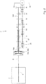
- the dual-clutch gearbox 7 comprises a pair of primary shafts 15 coaxial with and independent of one another and fitted one inside the other. Moreover, the dual-clutch gearbox 7 comprises two coaxial clutches 16, each of which is suitable to connect a corresponding primary shaft 15 to the drive shaft 5 of the internal combustion engine 4 by means of interposition of the drive shaft 8.
- Each clutch 16 is in an oil bath and is therefore pressure-controlled (i.e., the degree of opening/closing of the clutch 16 is determined by the oil pressure within said clutch 16); according to an alternative embodiment, each clutch 16 is dry and is therefore position-controlled (i.e., the degree of opening/closing of the clutch 16 is determined by the position of a mobile member of said clutch 16); thus, each clutch 16 comprises at least one solenoid valve that controls the oil entering the clutch 16 and controls the oil leaving the clutch 16.
- the dual-clutch gearbox 7 comprises a single secondary shaft 17 connected to the differential 9 which transmits the motion to the rear driving wheels 3; according to an alternative and equivalent embodiment, the dual-clutch gearbox 7 comprises two secondary shafts 17 both connected to the differential 9.
- the dual-clutch gearbox 7 has seven forward gears indicated by Roman numerals (first gear I, second gear II, third gear III, fourth gear IV, fifth gear V, sixth gear VI and seventh gear VII) and one reverse gear (indicated by the letter R).
- the primary shaft 15 and the secondary shaft 17 are mechanically coupled to one another by means of a plurality of gear pairs, each of which defining a corresponding gear and comprising a primary gear 18 fitted on the primary shaft 15 and a secondary gear 19 fitted on the secondary shaft 17.
- each primary gear 18 is keyed to a corresponding primary shaft 15 so as to always rotate integrally with said primary shaft 15 and permanently meshes with the corresponding secondary gear 19; on the contrary, each secondary gear 19 is idly mounted on the secondary shaft 17.
- the dual-clutch gearbox 7 comprises four double synchronizers 20, each of which is fitted coaxially with respect to the secondary shaft 17, is arranged between two secondary gears 19, and is suitable to be operated to alternatively engage the two corresponding secondary gears 19 with the secondary shaft 17 (i.e., to alternatively make the two corresponding secondary gears 19 angularly integral with the secondary shaft 17).
- each synchronizer 20 may be moved in one direction to engage a secondary gear 19 with the secondary shaft 17, or it may be moved in the other direction to engage the other secondary gear 19 with the secondary shaft 17.
- the dual-clutch gearbox 7 comprises a single secondary shaft 17 connected to the differential 9 which transmits the motion to the rear driving wheels 3; according to an alternative and equivalent embodiment, the dual-clutch gearbox 7 comprises two secondary shafts 17 both connected to the differential 9.
- one clutch 16A is closed to transmit the motion to a primary shaft 15A which in turn transmits the motion to the secondary shaft 17 by means of the current gear A which is engaged; on the contrary, one clutch 16B is open and therefore isolates a primary shaft 15B from the drive shaft 8.
- the following gear B is engaged to connect the primary shaft 15B to the secondary shaft 17 by means of said gear B; such operation is performed automatically irrespective of the driver's wishes as soon as the clutch 16B is opened at the end of the previous gear shift.
- the gear shift is performed by opening the clutch 16A to disconnect the primary shaft 15A (thus the gear A) from the drive shaft 8 (i.e., from the drive shaft 5 of the engine 4) and simultaneously closing the clutch 16B to connect the primary shaft 15B (thus the gear B) to the drive shaft 8 (i.e., to the drive shaft 5 of the engine 4).
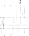
- figure 3 The methods for performing a conventional gear shift are illustrated in figure 3 , in which the driver sends the gear shift command (usually by operating a lever or button arranged on or in proximity of the steering wheel) at the moment T 0 ; figure 3 shows, starting from the top, the torques transmitted by the two clutches 16A and 16B, the speed ⁇ E of rotation of the drive shaft 5 of the engine 4, the longitudinal acceleration ⁇ of the vehicle 1, and the torque T E generated by the engine 4.
- the transmission control unit 12 As soon as the transmission control unit 12 receives the gear shift command from the driver (moment T 0 ), the transmission control unit 12 immediately starts filling the clutch 16B, that is to say, it immediately starts feeding oil under pressure into the clutch 16B; the clutch 16B associated with the following gear B can in fact only transmit a significant torque to the rear driving wheels 3 when the filling with oil under pressure has been completed and thus since said oil under pressure cannot occupy any further space inside the clutch 16B it exerts a force that stacks the discs of said clutch 16B.
- a certain delay time T R has to pass (usually between 80 and 220 milliseconds) during which the filling of oil inside the clutch 16B is completed.
- T R a certain delay time
- the completion of filling of the clutch 16B is monitored by means of a pressure sensor which detects the pressure of the oil inside said clutch 16B: when the pressure of the oil inside the clutch 16B exceeds a given threshold, it means the entire internal volume of the clutch 16B has been filled and the oil inside the clutch 16B starts to be compressed.
- the transfer of torque between the two clutches 16 occurs between the moments T 1 and T 2 , i.e., the torque transmitted by the clutch 16A gradually decreases and at the same time the torque transmitted by the clutch 16B gradually increases thus causing a crossing of the two clutches 16.
- the clutch 16A is opened within the same time that is necessary for the complete closing of the clutch 16B so as to achieve a symmetric crossing; in this crossing the torque generated by the engine 4 is kept constant, whereas the overall torque transmitted to the rear driving wheels 3 gradually decreases owing to the gradual lengthening of the gear ratio of the gearbox 7 (the clutch 16A is associated with the current gear A which is shorter than the following gear B associated with the clutch 16B).
- the interval between the moments T 1 and T 2 is the shifting time T C , during which the torque transmitted by the clutch 16A decreases until it is zero and the torque transmitted by the clutch 16B increases until reaching the torque T E generated by the engine 4, that is to say, during which the clutch 16A is separated from the rear driving wheels 3 and the clutch 16B is connected to the rear driving wheels 3.
- the speed ⁇ E of rotation of the drive shaft 5 of the engine 4 is equal to the speed ⁇ A of rotation imposed by the gear ratio of the current gear A before the gear shift, it gradually falls towards the speed ⁇ B of rotation imposed by the gear ratio of the following gear B and is equal to the speed ⁇ B of rotation after the gear shift.
- the speed ⁇ E of rotation of the drive shaft 5 is equal to (adheres to) the speed ⁇ A of rotation imposed by the gear ratio of the current gear A associated with the clutch 16A and is therefore only decreased after the clutch 16A has been fully opened; the aim of such method of controlling the speed ⁇ E of rotation of the drive shaft 5 is to prevent the clutch 16A from becoming a brake, i.e. generating a braking torque on the rear driving wheels 3.
- the control unit 11 of the engine 4 temporarily decreases the torque generated by said engine 4, as requested by the control unit 12 of the transmission 6; such temporary decrease in the torque generated by the engine 4 has the effect of decreasing the speed ⁇ E of rotation of the drive shaft 5 which passes from the initial value ⁇ A imposed by the gear ratio of the current gear A to the final value ⁇ B imposed by the gear ratio of the following gear B. It is important to note that the temporary decrease in the torque T E generated by the engine 4 does not affect the longitudinal acceleration ⁇ of the vehicle 1, as the torque transmitted by the clutch 16B to the rear driving wheels 3 remains constant.
- the interval between the moments T 2 and T 3 is the synchronization time T S during which the speed ⁇ E of rotation of the drive shaft 5 of the engine 4 falls from the speed ⁇ A of rotation imposed by the gear ratio of the current gear A to the speed ⁇ B of rotation imposed by the gear ratio of the following gear B, that is to say, the speed ⁇ E of rotation is synchronized with the speed ⁇ B of rotation.
- the longitudinal acceleration ⁇ of the vehicle 1 is in first approximation constant and equal to the value ⁇ A immediately before the gear shift, gradually decreases towards the value ⁇ B during the gear shift, and is in first approximation constant and equal to the value ⁇ B immediately after the gear shift.
- the decrease in the longitudinal acceleration ⁇ of the vehicle 1 during the gear shift is due to the fact that the torque generated by the engine 4 which remains substantially constant is transmitted with a gradually increasing gear ratio (the gear A is shorter than the gear B) and therefore a decreasing torque is applied to the rear driving wheels 3.
- the opening of the clutch 16A is practically instantaneous, in that it takes place at the maximum possible speed by means of a step command (variation); likewise, the closing of the clutch 16B is practically instantaneous, in that it takes place at the maximum possible speed by means of a step command (variation).
- the clutch 16B when the clutch 16B is ready to transmit a significant torque (that is to say, when the pressure of the oil inside the clutch 16B exceeds the predetermined threshold), the clutch 16B is closed by means of a step command (that is to say, to achieve a target of torque to be transmitted which varies by step, i.e., instantaneously, from zero to the maximum value and is always kept at the maximum value using open-loop control until the clutch 16B is completely closed) and thus at the maximum possible speed and, at the same time, the clutch 16A is opened by means of a step command (that is to say, to achieve a target of torque to be transmitted which varies by step, i.e., instantaneously from the current value to the zero value and is always kept at the zero value using open-loop control until the clutch 16A is completely open) and thus at the maximum possible speed.
- a step command that is to say, to achieve a target of torque to be transmitted which varies by step, i.e., instantaneously from the current
- the shifting time T c is much shorter than both the delay time T R and the synchronization time T S ; specifically, the shifting time T C is shorter than 20% (shorter than 15% in some cases) of the synchronization time T S .
- the filling of the clutch 16B can be performed extremely quickly, in that it is always possible to supply the greatest possible oil flow rate to the clutch 16B (constantly, for the entire filling operation): indeed, at the moment T 1 there is no need for any precise control of the position of the clutch 16B, as the clutch 16B must be completely closed at the maximum possible speed (thus with the filling solenoid valve completely open and a substantially open-chain control).
- the delay time T R required for filling the clutch 16B is approximately 80-100 milliseconds, whereas in the embodiment illustrated in figure 3 the delay time T R required for filling the clutch 16B is approximately 220-250 milliseconds.
- the precise and controlled filling of the clutch 16B takes approximately 120-140 milliseconds longer than the uncontrolled filling of the clutch 16B at the greatest possible oil flow rate (that is to say, with open-chain control of the oil supply).
- the current command of the solenoid valve that controls the filling of the clutch 16B may be appropriately operated to significantly reduce the time required for filling: nominal filling (the duration of which in time is a value of between 100 ms and 220 ms and is equal to the delay time T R comprised between the moments T 0 and T 1 ) permits the achievement of considerable precision in the torque transmitted by the clutch 16B as the steps in which the clutch 16B starts transmitting the torque and the step in which the transmitted torque gradually increases are separate.
- the filling time of the clutch 16B can be reduced by up to less than 65-75 ms (a time of 65-75 ms between the moments T 0 and T 2 is in fact necessary, so for a time interval greater than just the delay time T R which is comprised between the moments T 0 and T 1 ); in this way the steps in which the clutch 16B starts transmitting torque and the step in which the transmitted torque gradually increases overlap (in other words, the clutch 16B transmits the maximum torque in the same moment as when it starts transmitting torque).
- the clutch 16A must be opened instantaneously the moment the filling of the clutch 16B is completed; in order to achieve an instantaneous reduction in the torque of the clutch 16A an appropriate solenoid valve is operated to empty said clutch 16A.
- the solenoid valve of the clutch 16B upon receiving the gear shift command, is arranged and held in a completely open filling position (i.e. an oil input position) with open-loop control so that the clutch 16B is filled with oil that is always supplied at the greatest possible oil flow rate from the start until the end of filling; at the same time, the moment in which the oil filling in the clutch 16B ends is detected as previously described in detail.
- the solenoid valve of the clutch 16A is arranged and maintained in a completely open emptying position (i.e. an oil output position) with open-loop control so that the clutch 16A is emptied of the oil by always extracting the greatest possible oil flow rate from the start to the end of emptying.
- the precise and optimal synchronization of the actuation of the two clutches 16A and 16B is very important: lack of synchronization of the opening and closing of the two clutches 16A and 16B could result in a torque hole (if the clutch 16A is opened too soon with respect to the closing of the clutch 16B), or in blocking of the rear axle (if the clutch 16A is opened too late with respect to the closing of the clutch 16B).
- the driver notices a much faster (more immediate) response to his/her request to shift gear, as the delay time T R (that is to say, the time that elapses between when the request to shift gear is sent at the moment T 0 and a change in the dynamics of the vehicle 1 at the moment T 1 ) is significantly reduced (by more than 60%).
- the engine 4 is made to operate in cut-off (i.e., with the fuel supply completely cut off and thus with the maximum available engine braking) for a limited period of time; when the engine 4 is made to operate in cut-off, the speed ⁇ E of rotation of the drive shaft 5 suddenly falls, producing a "pleasant" noise that is greatly appreciated by drivers during high-performance driving.
- the control unit 11 of the engine 4 follows the torque and speed references imposed by the control unit 12 of the transmission 6.
- the torque profile is created so that in a given step in the synchronization time T S the torque profile is instantaneously reduced to zero (by means of a step variation) to make the engine 4 operate in cut-off and then instantaneously restored (by means of a step variation) to the previous value.
- Figure 6 shows an alternative embodiment of the gear shift operation illustrated in figures 4 and 5 , in which the opening of the clutch 16A does not start at the moment T 1 when the clutch 16B starts transmitting torque, but in advance of the moment T 1 , i.e., it starts before the clutch 16B starts transmitting torque.
- the method of performing the gear shift illustrated in figure 6 has been named "SIAMT"; this name stands for “SImulated AMT” and was chosen as the behaviour of a single-clutch gearbox is simulated, at least in part, by means of a dual-clutch gearbox only in order to change the driving perceptions felt by the driver.
- the advance in the opening of the clutch 16A is variable and may occur as a lower limit at the moment T 0 (as shown in figure 6 ) or may occur at a moment between the moment T 0 and the moment T 1 . In this manner, the driver feels that the transmission 6 responds extremely quickly to his/her gear shift command sent at the moment T 0 (i.e., after a short delay time) and even instantaneously when the opening of the clutch 16A starts at the moment T 0 as shown in figure 6 .
- the control unit 12 of the transmission 6 determines a target torque T E-TAR of the engine 4; the control unit 12 of the transmission 6 notifies the control unit 11 of the engine 4 of the target torque T E-TAR of the engine 4 by means of the BUS line 13 and/or by means of the dedicated synchronization cable 14, so that the control unit 11 of the engine 4 controls the engine 4 to pursue the target torque T E-TAR of the engine 4.
- the moment at which to start the opening of the clutch 16A is decided according to the desired speed of reaction to the gear shift command, i.e., how quickly the driver should feel an action of the transmission 6 after sending the gear shift command at the moment T 0 .
- the greater the desire to increase the driver's perception of responsiveness of the transmission 6 to the gear shift command the closer the moment at which the opening of the clutch 16A starts must be to the moment T 0 .
- it is worth underlining that in terms of performance and also in terms of the sensations felt by the driver, it is not always convenient to start the opening of the clutch 16A very much in advance (that is to say, it is not always convenient to start the opening of the clutch 16A immediately after the moment T 0 ).
- the clutch 16A performs draining (that is to say, emptying) in two successive ramps which also have different gradients so that the sum of the torques transmitted by the two clutches 16A and 16B (in other words, the total torque transmitted to the rear driving wheels 3) is always positive (otherwise the mechanics of the gearbox 7 could trigger oscillations due to the many spaces in the system); if the overall torque is moderate (in other words, when the vehicle 1 is driven gently) and the moment in which the opening of the clutch 16A starts is too far in advance, the initial downward gradient of the torque transmitted by the clutch 16A will be low and thus substantially hardly perceived by the driver or not perceived at all; in this case it is more advantageous not to anticipate the moment in which the opening of the clutch 16A starts by too much, in order to obtain a higher initial downward gradient of the torque transmitted by the clutch 16A which will therefore be felt by the driver.
- the opening of the clutch 16A in advance determines a degradation of performance as the more this is anticipated the more the torque generated by the engine 4 must be cut off; on the contrary, in a standard gear shift with a dual-clutch gearbox (illustrated for example in figure 3 ) the torque generated by the engine 4 is always kept constant with no need for it to be cut off.
- the actual degradation of performance determined by the opening of the clutch 16A in advance is felt in exactly the opposite way by the driver as an improvement in performance. In other words, for the majority of drivers a gear shift in which the opening of the clutch 16A is done in advance is better in terms of performance than a standard gear shift.
- the control unit 11 of the engine 4 temporarily decreases the torque T E generated by the engine 4 upon the request of the control unit 12 of the transmission 6, while maintaining the torque transmitted by the clutch 16B constant; consequently, a difference is created between the torque T E generated by the engine 4 and the torque transmitted by the clutch 16B (which is higher than the torque T E generated by the engine 4), and such difference has the effect of decreasing the speed ⁇ E of rotation of the drive shaft 5 which passes from the initial value ⁇ A imposed by the gear ratio of the current gear A to the final value ⁇ B imposed by the gear ratio of the following gear B.
- the torque T E generated by the engine 4 is increased (with respect to the control method illustrated in figure 6 ) and the clutch 16B is temporarily over-lengthened, thus increasing the oil pressure in order to transfer more torque to the rear driving wheels 3.
- the clutch 16B is controlled to temporarily transmit a torque that is greater than the torque to be transmitted by the clutch B immediately after the gear shift and than the torque transmitted by the clutch 16A immediately before the gear change.
- the clutch 16B is controlled to transmit to the rear driving wheels 3 a higher torque than the torque T E generated by the engine 4, so as to gradually reduce the speed ⁇ E of rotation of the drive shaft 5 from the initial value ⁇ A to the final value ⁇ B ; in this situation, the clutch 16B is controlled to transmit to the rear driving wheels 3 both the torque T E generated by the engine 4, and a further (extra) torque generated by the reduction of the kinetic energy of the drive shaft 5 (i.e., generated by the slowing down of the drive shaft 5).
- the above-described method of temporarily over-lengthening the clutch 16B makes it possible to increase acceleration performance: between the moments T 2 and T 3 the temporary increase in the engine torque delivered to the rear driving wheels 3 results in a corresponding temporary increase in the longitudinal acceleration ⁇ . Moreover, the above-described method of temporarily over-lengthening the clutch 16B means the synchronization time T S can be significantly reduced, which also contributes towards creating a feeling of sportiness.
- the best possible performance can be achieved by combining a substantial over-lengthening of the clutch 16B without any cutting off of the torque T E generated by the engine 4 (that is to say, the torque T E generated by the engine 4 is always kept constant during the entire gear shifting operation). It is worth noting that the above-mentioned method of temporarily over-lengthening the clutch 16B achieves benefits in terms of improved performance but also results in a slight lessening of driving comfort as the increase and subsequent decrease in the longitudinal acceleration ⁇ within a short time (approximately 80-150 milliseconds) result in an oscillatory movement of the head of the vehicle's occupants around the "hinging" of the neck.
- the vehicle's occupants perceive the movements of the head backwards (when the longitudinal acceleration ⁇ increases) and forwards (when the longitudinal acceleration ⁇ decreases) as uncomfortable when these do not occur during high-performance driving.
- the above-described method of temporarily over-lengthening the clutch 16B is only used when the highest possible performance is sought in sports driving.
- the time for which the clutch 16B is over-lengthened can be increased; in other words, the clutch 16B is over-lengthened to transmit an additional lower torque over a longer time. In this way the step of longitudinal acceleration ⁇ of the vehicle 1 is reduced (but not eliminated) and is therefore less noticeable by the occupants of the vehicle 1.
- Figures 4-7 show an upward gear shift in which the current gear A is shorter than the following gear B.
- the method of performing the gear shift described above may also be applied in an entirely equivalent manner to a downward gear shift in which the current gear A is longer than the following gear B as illustrated in figures 8 and 9 , provided the road vehicle 1 is slowing down (i.e., when the torque T E generated by the engine 4 is zero and not for example in the case of "kickdown" when the torque T E generated by the engine 4 is significantly more than zero) .
- Figure 8 shows a downward gear shift in which the clutch 16B is filled with oil which is always supplied at the maximum possible oil flow rate; this downward gear shift is exactly the same as the upward gear shift illustrated in figure 4 , with the difference that in the downward gear shift the longitudinal acceleration ⁇ is negative, the engine 4 does not generate torque T E (that is to say, the torque T E is normally zero), and during gear shifting the driving shaft 5 of the engine 4 accelerates instead of slowing down.
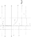
- Figure 9 shows a downward gear shift that differs from the downward gear shift illustrated in figure 8 for the fact that, after the complete closing of the clutch 16B, the clutch 16B is controlled to temporarily over-lengthen and thus transmit a torque that is greater than the torque to be transmitted by the clutch 16B immediately after the gear shift and than the torque transmitted by the clutch 16A immediately before the gear change; in this way, the torque needed to make the drive shaft 5 accelerate is "drawn" from the motion of the road vehicle 1 and there is no need to activate the engine 4 during the synchronization time T S (as is the case in the example illustrated in figure 8 ).
- the strategy illustrated in figure 9 is more energy efficient, since the engine 4 is not required to generate any torque T E and therefore no fuel is used during gear shifting.
- the control unit 12 of the transmission 6 selectively uses the different methods of performing a gear shift described above ( “superfill”, “torque hole”, “overtorque”, “emptying of deactivated clutch” ) according to the current driving style, that is to say, if the vehicle 1 is being driven in comfort mode, energy efficiency mode, sports driving mode or racing driving mode.
- the current driving style may be determined directly by the driver by operating a specific control knob (known under the trade name of "manettino” ), it may be determined automatically according to the motion of the vehicle 1 (specifically as a function of the speed and longitudinal and lateral acceleration of the vehicle 1), or it may be determined according to both the selection made by the driver and the motion of the vehicle 1.
- the control unit 12 of the transmission 6 performs the upward gear shifts (that is to say, gear shifts during acceleration to lengthen the gear ratio) using the "superfill” method only (i.e., without using the "torque hole”, “overtorque” or “emptying of deactivated clutch” methods) and thus operates as illustrated in figure 4 .
- This method guarantees the precision of the gear shifting manoeuvre with a monotonic acceleration from the initial value to the final value; shifting is extremely comfortable and also fast since the response time to the gear shift command (that is to say, the delay time T R ) is considerably shorter than that achieved with a conventional gear shift.
- the control unit 12 of the transmission 6 performs the upward gear shifts (that is to say, gear shifts during acceleration to lengthen the gear ratio) using the "superfill” and “overtorque” methods (i.e., without using the "torque hole” and “emptying of deactivated clutch” methods); this embodiment is illustrated in figure 9 with reference to a downward gear shift (namely, a gear shift during deceleration to shorten the gear ratio) and can easily be applied to an upward gear shift based on that illustrated in figure 6 and adding the "overtorque” method.
- the gear shift is performed without wasting any of the energy generated by the engine 4: during the synchronization time T S (that is to say, during the step of synchronizing the speed ⁇ E of rotation of the drive shaft 5 of the engine 4 with the speed ⁇ B of rotation imposed by the gear ratio of the following gear B) the mechanical energy generated by the engine 4 and part of the kinetic energy of the drive shaft 5 of the engine 4, which thus slows down, is transmitted to the rear driving wheels 3.
- Gear shifting is extremely comfortable as well as fast since the response time to the gear shift command (that is to say, the delay time T R ) is considerably shorter than that achieved with a conventional gear shift; furthermore, thanks to the over-lengthening of the clutch 16B, the speed ⁇ E of rotation of the drive shaft 5 of the engine 4 adapts more quickly to the speed ⁇ B of rotation imposed by the gear ratio of the following gear B (that is to say, the synchronization time T S is shorter than with a conventional gear shift) and this is seen by the driver as evidence of the sportiness of the entire gear shifting event.
- the control unit 12 of the transmission 6 performs the upward gear shifts (that is to say, gear shifts during acceleration to lengthen the gear ratio) using the "superfill” and "emptying of deactivated clutch” methods (in other words, without using the "torque hole” or “overtorque” methods); this embodiment is not illustrated and can easily be understood starting from that illustrated in figure 6 and removing the "torque hole” method. With this method it is possible to achieve an acceleration profile with high time derivatives that make the vehicle 1 aggressive without undermining driving precision.
- the "emptying of deactivated clutch” method though not ideal in terms of longitudinal acceleration, makes gear shifting a particularly exciting experience for the driver that is much appreciated.
- control unit 12 of the transmission 6 could also perform the upward gear shifts (that is to say, gear shifts during acceleration to lengthen the gear ratio) using the "torque hole” method, that is to say, using the "superfill”, “emptying of deactivated clutch” and “torque hole” methods together (i.e., without using the "overtorque” method) and thus operate as illustrated in figure 6 .
- the speed ⁇ E of rotation of the drive shaft 5 of the engine 4 adapts more quickly to the speed ⁇ B of rotation imposed by the gear ratio of the following gear B (i.e., the synchronization time T S is shorter than with a conventional gear shift) and, above all, the exhaust noise is entirely similar to the exhaust noise typical of racing cars.
- the control unit 12 of the transmission 6 could perform the upward gear shifts (that is to say, gear shifts during acceleration to lengthen the gear ratio) using all four methods, ( “superfill”, “emptying of deactivated clutch” , “torque hole” and “overtorque” ) and thus operate as illustrated in figure 7 .
- gear shifting is fast thanks to the effect of the "superfill” method (reduction of the delay time T R ) and thanks to the effect of the “torque hole” method (reduction of the synchronization time T S ), sporty thanks to the effect of the "emptying of deactivated clutch” method (which achieves an acceleration profile with high time derivatives), efficient thanks to the effect of the "overtorque” method (which recovers part of the kinetic energy of the drive shaft 5 of the engine 4), and exciting thanks to the effect of the "torque hole” method (which makes the noise of the exhaust entirely similar to that typical of racing vehicles).
- the control unit 12 of the transmission 6 performs the downward gear shifts (that is to say, gear shifts during deceleration to shorten the gear ratio) using the "superfill” and “overtorque” methods (i.e., without using the "torque hole”, or “emptying of deactivated clutch” methods) and thus operates as illustrated in figure 9 .
- This guarantees the precision of the gear shifting manoeuvre with a monotonic deceleration from the initial value to the final value; gear shifting is extremely comfortable (especially in terms of the noise level, as the engine 4 is always deactivated) and also fast since the response time to the gear shift command (that is to say, the delay time T R ) is considerably shorter than that achieved with a conventional gear shift.
- control unit 12 of the transmission 6 could request the activation of the engine 4 to generate a torque in order to reduce any discontinuities in longitudinal acceleration to a minimum during the synchronization of the speed ⁇ E of rotation of the drive shaft 5 of the engine 4 and the speed ⁇ B of rotation imposed by the gear ratio of the following gear B; of course, in this situation, the engine 4 is controlled to reduce the noise of the exhaust to a minimum, which could affect the speed of the manoeuvre, i.e., by having to make the synchronization time T S longer.
- the control unit 12 of the transmission 6 performs the downward gear shifts (that is to say, gear shifts during deceleration to shorten the gear ratio) using the "superfill” and “overtorque” methods (that is to say, without using the "torque hole", or "emptying of deactivated clutch” methods) and thus operates as illustrated in figure 9 .
- the control unit 12 of the transmission 6 performs the downward gear shifts (that is to say, gear shifts during deceleration to shorten the gear ratio) using the "superfill” method (i.e., without using the "torque hole”, “overtorque” or “emptying of deactivated clutch” methods) and thus operates as illustrated in figure 8 .
- control unit 12 of the transmission 6 could perform the downward gear shifts also partially using the "overtorque”, method, in other words, the synchronization of the speed ⁇ E of rotation of the drive shaft 5 of the engine 4 with the speed ⁇ B of rotation imposed by the gear ratio of the following gear B is performed partly by using the kinetic energy of the vehicle 1 (as an effect of the "overtorque” method) and partly using the torque generated by the engine 4 which is activated; this control logic is not illustrated but can easily be applied by combining that illustrated in figures 8 and 9 (of course, both the engine torque generated by the "overtorque” method, and the torque generated by the engine 4 are reduced as, since they are both present, they contribute together to accelerate the drive shaft 5 of the engine 4).
- Gear shifting is perceived as fast since the response time to the gear shift command (in other words, the delay time T R ) is considerably shorter than that achieved with a conventional gear shift. Furthermore, when the engine 4 is activated, the noise that is generated gives the vehicle 1 an aggressiveness typical of sports cars. Clearly, in this situation the engine 4 is controlled both to reduce the synchronization time T S to a minimum (that is to say, to complete the gear shift as quickly as possible) and to accentuate the noise of the exhaust; specifically, the racing driving style envisages carrying the speed of the manoeuvre and the noise of the exhaust to the extreme.
- control method for carrying out a gear shift described above is simple and inexpensive to implement as it does not require the installation of additional physical components and does not involve upgrading of the control unit 12 of the transmission 6 since it does not require significant additional computing capacity.
Landscapes
- Engineering & Computer Science (AREA)
- Mechanical Engineering (AREA)
- Chemical & Material Sciences (AREA)
- Combustion & Propulsion (AREA)
- General Engineering & Computer Science (AREA)
- Transportation (AREA)
- Automation & Control Theory (AREA)
- Physics & Mathematics (AREA)
- Fluid Mechanics (AREA)
- Control Of Transmission Device (AREA)
Claims (14)
- Steuerungsverfahren zum Durchführen eines Gangschaltvorgangs in einem Antriebsstrang (6), der mit einem Doppelkupplungsgetriebe (7) ausgestattet ist, um von einem aktuellen Gang (A) in einen folgenden Gang (B) zu schalten;
wobei der Antriebsstrang (6) ein Doppelkupplungsgetriebe (7) mit zwei Primärwellen (15), mindestens einer Sekundärwelle (17), die mit den Antriebsrädern (3) verbunden ist, und zwei Kupplungen (16) aufweist, von denen jede zwischen einer Antriebswelle (5) eines Motors (4) und einer entsprechenden Primärwelle (15) angeordnet ist, sich in einem Ölbad befindet und druckgeregelt ist, nämlich wird der Öffnungs- bzw. Schließgrad der Kupplung (16) durch den Druck des Öls auf der Innenseite der Kupplung (16) bestimmt;
wobei jede Kupplung (16A, 16B) mindestens ein Magnetventil aufweist, das den Einlass von Öl in die Kupplung (16A, 16B) und den Auslass von Öl aus der Kupplung (16A, 16B) steuert;
wobei das Steuerungsverfahren die folgenden Schritte aufweist:Empfangen eines Gangschaltbefehls,Öffnen einer mit dem aktuellen Gang (A) assoziierten ersten Kupplung (16A);Füllen einer mit dem folgenden Gang (B) assoziierten zweiten Kupplung (16B) mit Öl nach Empfang des Gangschaltbefehls; undSchließen der zweiten Kupplung (16B), sobald die Füllung mit Öl endet;das Steuerungsverfahren ist dadurch gekennzeichnet, dass es die folgenden weiteren Schritte aufweist:Anordnen und Halten des Magnetventils der zweiten Kupplung (16B) nach Empfang des Gangschaltbefehls in einer vollständig geöffneten Füllposition mit rückführungsloser Steuerung, so dass die zweite Kupplung (16B) mit Öl gefüllt wird, das vom Beginn bis zum Ende des Füllvorgangs stets mit der größtmöglichen Ölflussrate zugeführt wird und die zweite Kupplung (16B) anschließend geschlossen wird, wobei das Magnetventil in der vollständig geöffneten Füllposition gehalten wird, bis die zweite Kupplung (16B) vollständig geschlossen ist;Erkennen des Moments, in dem das Füllen der zweiten Kupplung (16B) mit Öl endet und somit das Schließen der zweiten Kupplung (16B) beginnt; undsobald das Füllen von Öl in die zweite Kupplung (16B) endet, Anordnen und Halten des Magnetventils der ersten Kupplung (16A) in einer vollständig geöffneten Leerungsposition mit rückführungsloser Steuerung, so dass die erste Kupplung (16A) vom Öl geleert und dann geöffnet wird, wobei von Anfang bis Ende des Entleerungsvorgangs stets mit der größtmöglichen Ölflussrate entleert wird. - Steuerungsverfahren nach Anspruch 1 und aufweisend die weiteren Schritte:Bestimmen des Öldrucks im Inneren der zweiten Kupplung (16B) undFestlegen, dass das Füllen der zweiten Kupplung (16B) mit Öl beendet ist, wenn der Öldruck auf der Innenseite der zweiten Kupplung (16B) einen Schwellenwert überschreitet.
- Steuerungsverfahren nach Anspruch 1 oder 2 und aufweisend den weiteren Schritt: Einstellen des vom Motor (4) erzeugten Drehmoments (TE) nach dem vollständigen Öffnen der ersten Kupplung (16A), um die Drehzahl (ωE) der Antriebswelle (5) mit der vom Übersetzungsverhältnis des folgenden Gangs (B) eingebrachten Drehzahl (ωB) zu synchronisieren.
- Steuerungsverfahren nach Anspruch 3, wobei der Motor (4) während der Synchronisierung der Drehzahl (ωE) der Antriebswelle (5) und der vom Übersetzungsverhältnis des folgenden Gangs (B) eingebrachten Drehzahl (ωB) für eine begrenzte Zeit zum Betrieb ohne Kraftstoffversorgung veranlasst wird.
- Steuerungsverfahren nach Anspruch 4, wobei der Motor (4) zum Betrieb ohne Kraftstoffversorgung veranlasst wird, indem ein vom Motor (4) erzeugtes Zieldrehmoment (TE) durch eine Schrittveränderung auf Null reduziert und danach wiederhergestellt wird.
- Steuerungsverfahren nach Anspruch 4 oder 5, das im Fall des Hochschaltens die weiteren Schritte aufweist:Bestimmen, ob ein Fahrstil ein Sportfahrstil oder ein Rennfahrstil ist; undVeranlassen des Motors (4) zum Betrieb ohne Kraftstoffzufuhr während der Synchronisierung der Drehzahl (ωE) der Antriebswelle (5) und der vom Übersetzungsverhältnis des folgenden Gangs (B) eingebrachten Drehzahl (ωB) nur im Fall des Sport- oder Rennfahrstils.
- Steuerungsverfahren nach einem der Ansprüche 1 bis 6, wobei eine Schaltzeit (TC), in der die erste Kupplung (16A) mit maximal möglicher Geschwindigkeit vollständig geöffnet und die zweite Kupplung (16B) mit maximal möglicher Geschwindigkeit vollständig geschlossen wird, kürzer ist als die nachfolgende Synchronisationszeit (TS), in der die Drehzahl (ωE) der Antriebswelle (5) mit der vom Übersetzungsverhältnis des folgenden Gangs (B) eingebrachten Drehzahl (ωE) synchronisiert wird.
- Steuerungsverfahren nach Anspruch 7, wobei die Schaltzeit (TC) kürzer als 20 % der Synchronisationszeit (TS) ist.
- Steuerungsverfahren nach einem der Ansprüche 1 bis 8 und aufweisend den weiteren Schritt: Öffnen der ersten Kupplung (16A) erst am Ende der Öleinfüllung in die zweite Kupplung (16B) und wenn die zweite Kupplung (16B) geschlossen ist.
- Steuerungsverfahren nach einem der Ansprüche 1 bis 8 und aufweisend den weiteren Schritt: teilweises Öffnen der ersten Kupplung (16A) vor dem Ende der Öleinfüllung in die zweite Kupplung (16B) und bevor die zweite Kupplung (16B) geschlossen ist.
- Steuerungsverfahren nach Anspruch 10 und aufweisend den weiteren Schritt: Reduzieren des vom Motor (4) erzeugten Drehmoments (TE), wenn die erste Kupplung (16A) teilweise geöffnet ist, um die Drehzahl (ωE) der Antriebswelle (5) konstant und gleich einem Anfangswert (ωA) zu halten, bis die erste Kupplung (16A) vollständig geöffnet ist.
- Steuerungsverfahren nach einem der Ansprüche 1 bis 11 und aufweisend den weiteren Schritt: Steuern der zweiten Kupplung (16B) nach dem vollständigen Schließen der zweiten Kupplung (16B), um der zweiten Kupplung (16B) das vorübergehende Übertragen eines Drehmoments zu gestatten, das größer als das von der zweiten Kupplung (16B) unmittelbar nach dem Gangschalten zu übertragende Drehmoment und als das von der ersten Kupplung (16A) unmittelbar vor dem Gangschalten übertragene Drehmoment ist.
- Steuerungsverfahren nach Anspruch 12, das im Fall des Herunterschaltens die weiteren Schritte aufweist:Bestimmen, ob ein Fahrstil ein Energieeffizienz-Fahrstil ist; undim Fall eines Energieeffizienz-Fahrstils kein Aktivieren des Motors (4) zum Erzeugen eines Drehmoments nach dem vollständigen Öffnen der ersten Kupplung (16A) und vor dem vollständigen Schließen der zweiten Kupplung (16B).
- Steuerungsverfahren nach einem der Ansprüche 1 bis 13, das im Fall des Herunterschaltens die weiteren Schritte aufweist:Bestimmen, ob ein Fahrstil ein Sportfahrstil oder ein Rennfahrstil ist; undnur im Fall des Rennfahrstils Aktivieren des Motors (4) zum Erzeugen eines Drehmoments nach dem vollständigen Öffnen der ersten Kupplung (16A) und zum Synchronisieren der Drehzahl (ωE) der Antriebswelle (5) und der vom Übersetzungsverhältnis des folgenden Gangs (B) eingebrachten Drehzahl (ωB).
Applications Claiming Priority (1)
| Application Number | Priority Date | Filing Date | Title |
|---|---|---|---|
| ITUB2015A003377A ITUB20153377A1 (it) | 2015-09-03 | 2015-09-03 | Metodo di controllo per l'esecuzione di un cambio marcia in una trasmissione provvista di un cambio a doppia frizione |
Publications (2)
| Publication Number | Publication Date |
|---|---|
| EP3139070A1 EP3139070A1 (de) | 2017-03-08 |
| EP3139070B1 true EP3139070B1 (de) | 2020-08-19 |
Family
ID=54705748
Family Applications (1)
| Application Number | Title | Priority Date | Filing Date |
|---|---|---|---|
| EP16187106.6A Active EP3139070B1 (de) | 2015-09-03 | 2016-09-02 | Steuerungsverfahren zum durchführen eines gangschaltvorgangs in einem doppelkupplungsgetriebe |
Country Status (3)
| Country | Link |
|---|---|
| US (1) | US10046769B2 (de) |
| EP (1) | EP3139070B1 (de) |
| IT (1) | ITUB20153377A1 (de) |
Families Citing this family (15)
| Publication number | Priority date | Publication date | Assignee | Title |
|---|---|---|---|---|
| DE102016215220A1 (de) * | 2016-08-16 | 2018-02-22 | Zf Friedrichshafen Ag | Verfahren zum Betreiben eines Doppelkupplungsgetriebes mit einem zwei Kupplungen umfassenden Doppelkupplungssystem |
| CN109421727B (zh) * | 2017-08-31 | 2020-08-28 | 上海汽车集团股份有限公司 | 一种换挡过程中的发动机目标转速的确定方法及装置 |
| US10787174B2 (en) * | 2017-10-13 | 2020-09-29 | Toyota Motor Engineering & Manufacutring North America, Inc. | Automatic vehicle driving mode system |
| CN109973641B (zh) * | 2018-05-31 | 2020-07-28 | 长城汽车股份有限公司 | 一种换挡控制方法和装置 |
| KR102053434B1 (ko) * | 2018-11-16 | 2019-12-06 | 현대자동차(주) | 하이브리드 차량의 전동식 오일펌프 제어방법 |
| CN111963676B (zh) * | 2019-05-20 | 2022-02-01 | 上海汽车集团股份有限公司 | 汽车及其湿式双离合变速箱的控制方法和控制器 |
| CN110645349B (zh) * | 2019-09-06 | 2021-01-19 | 吉利汽车研究院(宁波)有限公司 | 一种混动车辆的双离合器换挡控制方法、装置及设备 |
| IT201900017513A1 (it) | 2019-09-30 | 2021-03-30 | Ferrari Spa | Metodo di controllo per l'esecuzione di un cambio marcia discendente mentre un pedale dell'acceleratore e' rilasciato in una trasmissione provvista di un cambio servoassistito a doppia frizione |
| IT201900017528A1 (it) * | 2019-09-30 | 2021-03-30 | Ferrari Spa | Metodo di controllo per l'esecuzione di un cambio marcia discendente con pedale dell'acceleratore rilasciato in una trasmissione provvista di un cambio servoassistito a doppia frizione |
| DE102019132589A1 (de) * | 2019-12-02 | 2021-06-02 | Audi Ag | Verfahren zum Durchführen eines Gangwechsels bei einem Kraftfahrzeug mit Automatikgetriebe beim Hochschalten im Volllastbetrieb |
| DE102020201855B4 (de) | 2020-02-14 | 2025-10-30 | Volkswagen Aktiengesellschaft | Verfahren zum Steuern und / oder Regeln der Kupplungen und / oder der Gangstufenwechsel eines Doppelkupplungsgetriebes |
| CN113048161B (zh) * | 2021-03-08 | 2022-07-19 | 重庆青山工业有限责任公司 | 一种湿式dct离合器充油过程的调节控制方法 |
| IT202300025980A1 (it) * | 2023-12-05 | 2025-06-05 | Ferrari Spa | Manopola selettrice per un autoveicolo |
| IT202300025962A1 (it) * | 2023-12-05 | 2025-06-05 | Ferrari Spa | Manopola selettrice per un autoveicolo |
| CN119572721B (zh) * | 2025-02-10 | 2025-04-25 | 成都赛力斯科技有限公司 | 离合器预充油的控制方法及装置 |
Family Cites Families (7)
| Publication number | Priority date | Publication date | Assignee | Title |
|---|---|---|---|---|
| DE10153722A1 (de) * | 2001-10-31 | 2003-05-22 | Volkswagen Ag | Verfahren zur Schaltsteuerung eines Lastschaltgetriebes |
| US6832978B2 (en) * | 2003-02-21 | 2004-12-21 | Borgwarner, Inc. | Method of controlling a dual clutch transmission |
| ITBO20090159A1 (it) * | 2009-03-18 | 2010-09-19 | Ferrari Spa | Metodo di controllo per l'esecuzione di un cambio marcia ascendente in una trasmissione manuale automatica provvista di un cambio a doppia frizione |
| IT1393611B1 (it) * | 2009-04-06 | 2012-05-08 | Ferrari Spa | Metodo di controllo per l'esecuzione di un cambio marcia in una trasmissione manuale automatica provvista di un cambio a doppia frizione |
| US8079936B2 (en) | 2009-04-09 | 2011-12-20 | Ford Global Technologies, Llc | Gear shift control of a dual clutch transmission |
| DE102009020651A1 (de) | 2009-05-08 | 2010-11-18 | Daimler Ag | Getriebevorrichtung |
| DE102011000957A1 (de) | 2011-02-28 | 2012-08-30 | Dr. Ing. H.C. F. Porsche Aktiengesellschaft | Verfahren zum Schalten eines halbautomatischen Lastschaltgetriebes |
-
2015
- 2015-09-03 IT ITUB2015A003377A patent/ITUB20153377A1/it unknown
-
2016
- 2016-09-01 US US15/254,947 patent/US10046769B2/en active Active
- 2016-09-02 EP EP16187106.6A patent/EP3139070B1/de active Active
Non-Patent Citations (1)
| Title |
|---|
| None * |
Also Published As
| Publication number | Publication date |
|---|---|
| EP3139070A1 (de) | 2017-03-08 |
| US20170088140A1 (en) | 2017-03-30 |
| ITUB20153377A1 (it) | 2017-03-03 |
| US10046769B2 (en) | 2018-08-14 |
Similar Documents
| Publication | Publication Date | Title |
|---|---|---|
| US10046769B2 (en) | Control method for carrying out a gear shift in a transmission provided with a dual-clutch gearbox | |
| EP2239484B1 (de) | Steuerungsverfahren zum Gangschalten in einem Doppelkupplungsgetriebe mit automatisierter Handschaltung | |
| EP2230144B1 (de) | Steuerverfahren zum Hochschalten eines automatisierten Schaltgetriebes mit einem Doppelkupplungsgetriebe | |
| US10197158B2 (en) | Motor vehicle having a dual clutch transmission | |
| EP3139069B1 (de) | Steuerungsverfahren zum durchführen eines gangschaltvorgangs in einem doppelkupplungsgetriebe | |
| EP3798478B1 (de) | Verfahren zur steuerung der ausführung des herunterschaltens bei gelöstem gaspedal in einem antriebsstrang mit einem servo-unterstützten doppelkupplungsgetriebe | |
| CN112576735B (zh) | 在释放加速器踏板的同时控制向较低档的变换的执行的方法 | |
| JP7577491B2 (ja) | デュアルクラッチサーボアシストトランスミッションを備えるドライブトレインでアクセルペダルが解放された状態でのより高速のギアへのシフトの実行を制御する、制御方法 | |
| EP2226524B1 (de) | Steuerverfahren zum Schließen einer Kupplung in einem automatischen Handschaltgetriebe | |
| EP3798476B1 (de) | Verfahren zur steuerung eines strassenfahrzeugs zur durchführung eines mehrfachen herunterschaltens in einem antriebsstrang mit einem servo-unterstützten getriebe | |
| EP2149728B1 (de) | Verfahren zur Steuerung eines Doppelkupplungsgetriebes |
Legal Events
| Date | Code | Title | Description |
|---|---|---|---|
| PUAI | Public reference made under article 153(3) epc to a published international application that has entered the european phase |
Free format text: ORIGINAL CODE: 0009012 |
|
| STAA | Information on the status of an ep patent application or granted ep patent |
Free format text: STATUS: THE APPLICATION HAS BEEN PUBLISHED |
|
| STAA | Information on the status of an ep patent application or granted ep patent |
Free format text: STATUS: REQUEST FOR EXAMINATION WAS MADE |
|
| AK | Designated contracting states |
Kind code of ref document: A1 Designated state(s): AL AT BE BG CH CY CZ DE DK EE ES FI FR GB GR HR HU IE IS IT LI LT LU LV MC MK MT NL NO PL PT RO RS SE SI SK SM TR |
|
| AX | Request for extension of the european patent |
Extension state: BA ME |
|
| 17P | Request for examination filed |
Effective date: 20170210 |
|
| GRAP | Despatch of communication of intention to grant a patent |
Free format text: ORIGINAL CODE: EPIDOSNIGR1 |
|
| STAA | Information on the status of an ep patent application or granted ep patent |
Free format text: STATUS: GRANT OF PATENT IS INTENDED |
|
| RIC1 | Information provided on ipc code assigned before grant |
Ipc: B60W 30/19 20120101ALI20200221BHEP Ipc: B60W 10/113 20120101ALI20200221BHEP Ipc: B60W 10/06 20060101ALI20200221BHEP Ipc: B60W 30/182 20200101ALI20200221BHEP Ipc: F16D 48/02 20060101ALI20200221BHEP Ipc: B60W 10/02 20060101ALI20200221BHEP Ipc: F16H 61/688 20060101AFI20200221BHEP |
|
| INTG | Intention to grant announced |
Effective date: 20200320 |
|
| GRAS | Grant fee paid |
Free format text: ORIGINAL CODE: EPIDOSNIGR3 |
|
| GRAA | (expected) grant |
Free format text: ORIGINAL CODE: 0009210 |
|
| STAA | Information on the status of an ep patent application or granted ep patent |
Free format text: STATUS: THE PATENT HAS BEEN GRANTED |
|
| AK | Designated contracting states |
Kind code of ref document: B1 Designated state(s): AL AT BE BG CH CY CZ DE DK EE ES FI FR GB GR HR HU IE IS IT LI LT LU LV MC MK MT NL NO PL PT RO RS SE SI SK SM TR |
|
| REG | Reference to a national code |
Ref country code: CH Ref legal event code: EP |
|
| REG | Reference to a national code |
Ref country code: DE Ref legal event code: R096 Ref document number: 602016042157 Country of ref document: DE |
|
| REG | Reference to a national code |
Ref country code: AT Ref legal event code: REF Ref document number: 1304299 Country of ref document: AT Kind code of ref document: T Effective date: 20200915 |
|
| REG | Reference to a national code |
Ref country code: IE Ref legal event code: FG4D |
|
| REG | Reference to a national code |
Ref country code: LT Ref legal event code: MG4D |
|
| REG | Reference to a national code |
Ref country code: NL Ref legal event code: MP Effective date: 20200819 |
|
| PG25 | Lapsed in a contracting state [announced via postgrant information from national office to epo] |
Ref country code: GR Free format text: LAPSE BECAUSE OF FAILURE TO SUBMIT A TRANSLATION OF THE DESCRIPTION OR TO PAY THE FEE WITHIN THE PRESCRIBED TIME-LIMIT Effective date: 20201120 Ref country code: LT Free format text: LAPSE BECAUSE OF FAILURE TO SUBMIT A TRANSLATION OF THE DESCRIPTION OR TO PAY THE FEE WITHIN THE PRESCRIBED TIME-LIMIT Effective date: 20200819 Ref country code: SE Free format text: LAPSE BECAUSE OF FAILURE TO SUBMIT A TRANSLATION OF THE DESCRIPTION OR TO PAY THE FEE WITHIN THE PRESCRIBED TIME-LIMIT Effective date: 20200819 Ref country code: NO Free format text: LAPSE BECAUSE OF FAILURE TO SUBMIT A TRANSLATION OF THE DESCRIPTION OR TO PAY THE FEE WITHIN THE PRESCRIBED TIME-LIMIT Effective date: 20201119 Ref country code: BG Free format text: LAPSE BECAUSE OF FAILURE TO SUBMIT A TRANSLATION OF THE DESCRIPTION OR TO PAY THE FEE WITHIN THE PRESCRIBED TIME-LIMIT Effective date: 20201119 Ref country code: HR Free format text: LAPSE BECAUSE OF FAILURE TO SUBMIT A TRANSLATION OF THE DESCRIPTION OR TO PAY THE FEE WITHIN THE PRESCRIBED TIME-LIMIT Effective date: 20200819 Ref country code: PT Free format text: LAPSE BECAUSE OF FAILURE TO SUBMIT A TRANSLATION OF THE DESCRIPTION OR TO PAY THE FEE WITHIN THE PRESCRIBED TIME-LIMIT Effective date: 20201221 Ref country code: FI Free format text: LAPSE BECAUSE OF FAILURE TO SUBMIT A TRANSLATION OF THE DESCRIPTION OR TO PAY THE FEE WITHIN THE PRESCRIBED TIME-LIMIT Effective date: 20200819 |
|
| REG | Reference to a national code |
Ref country code: AT Ref legal event code: MK05 Ref document number: 1304299 Country of ref document: AT Kind code of ref document: T Effective date: 20200819 |
|
| PG25 | Lapsed in a contracting state [announced via postgrant information from national office to epo] |
Ref country code: RS Free format text: LAPSE BECAUSE OF FAILURE TO SUBMIT A TRANSLATION OF THE DESCRIPTION OR TO PAY THE FEE WITHIN THE PRESCRIBED TIME-LIMIT Effective date: 20200819 Ref country code: NL Free format text: LAPSE BECAUSE OF FAILURE TO SUBMIT A TRANSLATION OF THE DESCRIPTION OR TO PAY THE FEE WITHIN THE PRESCRIBED TIME-LIMIT Effective date: 20200819 Ref country code: LV Free format text: LAPSE BECAUSE OF FAILURE TO SUBMIT A TRANSLATION OF THE DESCRIPTION OR TO PAY THE FEE WITHIN THE PRESCRIBED TIME-LIMIT Effective date: 20200819 Ref country code: PL Free format text: LAPSE BECAUSE OF FAILURE TO SUBMIT A TRANSLATION OF THE DESCRIPTION OR TO PAY THE FEE WITHIN THE PRESCRIBED TIME-LIMIT Effective date: 20200819 Ref country code: IS Free format text: LAPSE BECAUSE OF FAILURE TO SUBMIT A TRANSLATION OF THE DESCRIPTION OR TO PAY THE FEE WITHIN THE PRESCRIBED TIME-LIMIT Effective date: 20201219 |
|
| PG25 | Lapsed in a contracting state [announced via postgrant information from national office to epo] |
Ref country code: CZ Free format text: LAPSE BECAUSE OF FAILURE TO SUBMIT A TRANSLATION OF THE DESCRIPTION OR TO PAY THE FEE WITHIN THE PRESCRIBED TIME-LIMIT Effective date: 20200819 Ref country code: DK Free format text: LAPSE BECAUSE OF FAILURE TO SUBMIT A TRANSLATION OF THE DESCRIPTION OR TO PAY THE FEE WITHIN THE PRESCRIBED TIME-LIMIT Effective date: 20200819 Ref country code: SM Free format text: LAPSE BECAUSE OF FAILURE TO SUBMIT A TRANSLATION OF THE DESCRIPTION OR TO PAY THE FEE WITHIN THE PRESCRIBED TIME-LIMIT Effective date: 20200819 Ref country code: RO Free format text: LAPSE BECAUSE OF FAILURE TO SUBMIT A TRANSLATION OF THE DESCRIPTION OR TO PAY THE FEE WITHIN THE PRESCRIBED TIME-LIMIT Effective date: 20200819 Ref country code: EE Free format text: LAPSE BECAUSE OF FAILURE TO SUBMIT A TRANSLATION OF THE DESCRIPTION OR TO PAY THE FEE WITHIN THE PRESCRIBED TIME-LIMIT Effective date: 20200819 |
|
| REG | Reference to a national code |
Ref country code: CH Ref legal event code: PL |
|
| REG | Reference to a national code |
Ref country code: DE Ref legal event code: R097 Ref document number: 602016042157 Country of ref document: DE |
|
| PG25 | Lapsed in a contracting state [announced via postgrant information from national office to epo] |
Ref country code: MC Free format text: LAPSE BECAUSE OF FAILURE TO SUBMIT A TRANSLATION OF THE DESCRIPTION OR TO PAY THE FEE WITHIN THE PRESCRIBED TIME-LIMIT Effective date: 20200819 Ref country code: AL Free format text: LAPSE BECAUSE OF FAILURE TO SUBMIT A TRANSLATION OF THE DESCRIPTION OR TO PAY THE FEE WITHIN THE PRESCRIBED TIME-LIMIT Effective date: 20200819 Ref country code: AT Free format text: LAPSE BECAUSE OF FAILURE TO SUBMIT A TRANSLATION OF THE DESCRIPTION OR TO PAY THE FEE WITHIN THE PRESCRIBED TIME-LIMIT Effective date: 20200819 Ref country code: ES Free format text: LAPSE BECAUSE OF FAILURE TO SUBMIT A TRANSLATION OF THE DESCRIPTION OR TO PAY THE FEE WITHIN THE PRESCRIBED TIME-LIMIT Effective date: 20200819 |
|
| REG | Reference to a national code |
Ref country code: BE Ref legal event code: MM Effective date: 20200930 |
|
| PLBE | No opposition filed within time limit |
Free format text: ORIGINAL CODE: 0009261 |
|
| STAA | Information on the status of an ep patent application or granted ep patent |
Free format text: STATUS: NO OPPOSITION FILED WITHIN TIME LIMIT |
|
| PG25 | Lapsed in a contracting state [announced via postgrant information from national office to epo] |
Ref country code: SK Free format text: LAPSE BECAUSE OF FAILURE TO SUBMIT A TRANSLATION OF THE DESCRIPTION OR TO PAY THE FEE WITHIN THE PRESCRIBED TIME-LIMIT Effective date: 20200819 Ref country code: LU Free format text: LAPSE BECAUSE OF NON-PAYMENT OF DUE FEES Effective date: 20200902 |
|
| 26N | No opposition filed |
Effective date: 20210520 |
|
| PG25 | Lapsed in a contracting state [announced via postgrant information from national office to epo] |
Ref country code: LI Free format text: LAPSE BECAUSE OF NON-PAYMENT OF DUE FEES Effective date: 20200930 Ref country code: IE Free format text: LAPSE BECAUSE OF NON-PAYMENT OF DUE FEES Effective date: 20200902 Ref country code: SI Free format text: LAPSE BECAUSE OF FAILURE TO SUBMIT A TRANSLATION OF THE DESCRIPTION OR TO PAY THE FEE WITHIN THE PRESCRIBED TIME-LIMIT Effective date: 20200819 Ref country code: BE Free format text: LAPSE BECAUSE OF NON-PAYMENT OF DUE FEES Effective date: 20200930 Ref country code: CH Free format text: LAPSE BECAUSE OF NON-PAYMENT OF DUE FEES Effective date: 20200930 |
|
| PG25 | Lapsed in a contracting state [announced via postgrant information from national office to epo] |
Ref country code: TR Free format text: LAPSE BECAUSE OF FAILURE TO SUBMIT A TRANSLATION OF THE DESCRIPTION OR TO PAY THE FEE WITHIN THE PRESCRIBED TIME-LIMIT Effective date: 20200819 Ref country code: MT Free format text: LAPSE BECAUSE OF FAILURE TO SUBMIT A TRANSLATION OF THE DESCRIPTION OR TO PAY THE FEE WITHIN THE PRESCRIBED TIME-LIMIT Effective date: 20200819 Ref country code: CY Free format text: LAPSE BECAUSE OF FAILURE TO SUBMIT A TRANSLATION OF THE DESCRIPTION OR TO PAY THE FEE WITHIN THE PRESCRIBED TIME-LIMIT Effective date: 20200819 |
|
| PG25 | Lapsed in a contracting state [announced via postgrant information from national office to epo] |
Ref country code: MK Free format text: LAPSE BECAUSE OF FAILURE TO SUBMIT A TRANSLATION OF THE DESCRIPTION OR TO PAY THE FEE WITHIN THE PRESCRIBED TIME-LIMIT Effective date: 20200819 |
|
| P01 | Opt-out of the competence of the unified patent court (upc) registered |
Effective date: 20230525 |
|
| PGFP | Annual fee paid to national office [announced via postgrant information from national office to epo] |
Ref country code: DE Payment date: 20250926 Year of fee payment: 10 |
|
| PGFP | Annual fee paid to national office [announced via postgrant information from national office to epo] |
Ref country code: IT Payment date: 20250908 Year of fee payment: 10 |
|
| PGFP | Annual fee paid to national office [announced via postgrant information from national office to epo] |
Ref country code: GB Payment date: 20250923 Year of fee payment: 10 |
|
| PGFP | Annual fee paid to national office [announced via postgrant information from national office to epo] |
Ref country code: FR Payment date: 20250925 Year of fee payment: 10 |