EP3139127A1 - Pôle d'arpentage - Google Patents
Pôle d'arpentage Download PDFInfo
- Publication number
- EP3139127A1 EP3139127A1 EP15183972.7A EP15183972A EP3139127A1 EP 3139127 A1 EP3139127 A1 EP 3139127A1 EP 15183972 A EP15183972 A EP 15183972A EP 3139127 A1 EP3139127 A1 EP 3139127A1
- Authority
- EP
- European Patent Office
- Prior art keywords
- pole
- height
- wire
- surveying
- information
- Prior art date
- Legal status (The legal status is an assumption and is not a legal conclusion. Google has not performed a legal analysis and makes no representation as to the accuracy of the status listed.)
- Granted
Links
Images

Classifications
-
- G—PHYSICS
- G01—MEASURING; TESTING
- G01C—MEASURING DISTANCES, LEVELS OR BEARINGS; SURVEYING; NAVIGATION; GYROSCOPIC INSTRUMENTS; PHOTOGRAMMETRY OR VIDEOGRAMMETRY
- G01C15/00—Surveying instruments or accessories not provided for in groups G01C1/00 - G01C13/00
- G01C15/02—Means for marking measuring points
- G01C15/06—Surveyors' staffs; Movable markers
-
- G—PHYSICS
- G01—MEASURING; TESTING
- G01C—MEASURING DISTANCES, LEVELS OR BEARINGS; SURVEYING; NAVIGATION; GYROSCOPIC INSTRUMENTS; PHOTOGRAMMETRY OR VIDEOGRAMMETRY
- G01C15/00—Surveying instruments or accessories not provided for in groups G01C1/00 - G01C13/00
- G01C15/002—Active optical surveying means
Definitions
- the invention relates to a surveying pole for measuring the position of a point on the ground with the help of a geodetic instrument.
- congeneric surveying poles for staking out and measuring terrain points or similar devices are known from prior art, for example from US 7,788,815 B2 , EP 1 130 355 A2 or JP 2000 234933 A .
- a position measurement is not taken of the target point directly, but rather of a reflector, a receiver or an antenna on the surveying pole.
- a conclusion to the position of the target point is possible due to the known spatial relationship between the reflector, the receiver or antenna, and the tip of the pole. With this method it is possible to circumvent obstacles which stand in the direct way between the measuring instrument and the target point.
- a pole adjustable in its height Said surveying pole is typically used together with a geodetic device comprising a measuring light sender and a measuring light receiver.
- the measuring light source (such as a rotating laser device) can emit a plane of light that defines a reference plane at a known elevation, wherein the reference plane may be level or sloping.
- the reference plane may be level or sloping.
- the pole can be given an indication by the geodetic instrument, when visual contact has been obtained. From that, the pole can give notice to its user by an audible, vibratory and/or visual signal.
- Survey pole solutions comprising a GNSS antenna are not reliant on a terrestrial geodetic instrument as they obtain their positional data via a satellite positioning system.
- a GNSS reference station might be provided at the scene.
- the surveyor places the pole tip onto the measuring point, levels the pole and triggers the GNSS measurement, the results of which include also height information.
- a surveying pole comprises at least two pole sections being telescopically insertable into each other so that a height adjustment of the pole is provided, a pointing tip at the lower end of the pole for setting the pole on a terrain point, a position giving means arranged on the pole, a height measuring system for measuring the height of the position giving means relative to the terrain point, wherein the height measuring system comprises a magneto-strictive wire placed inside of the pole, a magnet interacting with the wire, the positioning of the magnet relative to the wire being linked to the height adjustment of the pole, a sensor circuitry for emitting current pulses through the wire, a signal transducer, in particular comprising a sensing coil, for transforming mechanical waves of the wire into electrical signals, and a decoder for evaluating the signals and the current pulses, and therewith deriving the height of the position giving means.
- the magnet is arranged surrounding the sensor wire and particularly has a toroidal shape.
- the position giving means thereby comprise a reflector cooperating with a geodetic instrument, and/or a GNSS antenna.
- the pole can further comprise an inertial measuring unit with a defined spatial position relative to the pointing tip, wherein the inertial measuring unit comprises IMU-sensors including accelerometers and gyroscopes.
- IMU-sensors including accelerometers and gyroscopes.
- the pole comprises a wireless communication means, such as a Bluetooth or radio device by way of example, for transmitting and receiving information between the pole and a receiving device, the receiving device particularly being a geodetic instrument.
- the information can be particularly at least one of the following: height information acquired by the height measuring system of the pole, tilting information acquired by the inertial measuring unit, and position information acquired by the GNSS antenna and/or by a geodetic instrument with means of the reflector.
- a wired communication means could also be used for transmitting and receiving information between the pole and a receiving device.
- the pole may comprise a controller unit for controlling, feeding and reading the wireless communication means, storing the height information, particularly in combination with the tilting information and/or the position information, and making said information retrievable by the user.
- the controller unit may have an alert functionality which is capable of creating a warning signal after recognizing an unusual height adjustment, particularly an abrupt adjustment and/or an abnormally large adjustment.
- Electric power supply means particularly a battery unit, can be stored in a housing, which is attached to the pole, wherein the electric power supply means is exchangeable.
- a surveying pole is provided with an automatic height measuring functionality for position giving means, wherein the height measurement is performed based on magneto-strictive sensor technology.
- the position giving means e.g. a GNSS receiver or a retroreflector for use with a total station - are placed on the body of the survey pole with a defined spatial relation to the tip. This spatial relation is variable due to the adjustability of the pole and measurable with means of the automatic height measuring functionality.
- the pole comprises at least two pole sections (rods or tubes) which are telescopically insertable into each other so that a height adjustment of the pole is provided.
- a magneto-strictive wire sensor is placed inside the pole and serves as a waveguide.
- Such wire sensor is made by copper, by way of example.
- the sensor is positioned in such a way that its axis is parallel or coaxial to the pole's long axis (i.e. the axis of the pole's rods).
- the sensor is - at least in part - surrounded by a magnet, preferably a permanent ring-magnet, whereby magnet and sensor are mounted within the pole such that they are moveably relative to each other. This relative mobility is provided in the direction of the pole's long axis and is coupled directly, or reduced by gearing, with the height adjustment of the pole.
- the magneto-strictive wire sensor is fixedly mounted relative to a first pole section, the first pole section comprising a pointing tip for setting the pole on a terrain point, and comprising a grip for handling the pole.
- a second pole section is telescopically joined with the first pole section, and further pole sections might be joined accordingly.
- One of the further (other than the first) pole sections carries the position giving means and comprises the magnet encompassing the wire sensor in a contactless way.
- the magneto-strictive wire sensor can be fixedly mounted relative to any one of the further (other than the first) pole sections, which preferably carries the position giving means. In these other embodiments, the magnet is fixedly located in the first pole section.
- the height adjustment of the pole with means of moving the pole sections relative to each other causes the wire sensor on the one hand and the magnet on the other hand to also move relative to each other in a known ratio.
- the sensor circuitry emits pulses of current through its wire, generating a circular magnetic field.
- the magnet magnetizes the wire axially with its magnetic field and as both magnetic fields (the one of the sensor and the one of the magnet) are superimposed, a torsion wave is generated by the relative movement of said components.
- the torsion wave travels in both directions along the wire.
- One of the torsion waves runs directly to the sensor end comprising a signal transducer, while the other one is reflected at the end of the wire sensor.
- the wire sensor hence, works as a waveguide.
- the time between emission of the current pulse and the arrival of the wave at the signal transducer is measured. Therefore, an absolute metering of the position of the magnet is taking place by means of time measurement of the wave travel within the sensor wire.
- the surveying pole according to the invention is resistant to shocks up to 100 G, usable in a broad range of temperature and water-resistant according to IP68.
- the signal transducer of the wire sensor can be embodied as a sensing coil wrapped around the magneto-strictive wire.
- the signals sensed by the coil are sent to a filter and an amplifier from which a micro controller unit (MCU) can process the signals to length information.
- MCU micro controller unit
- the sensor wire needs to be so long that the magnet is still surrounding the wire in the longest extracting position of the pole, it protrudes at least one of the pole sections for such a long length, that it is preferably supported by a spacer at an adequate position, the spacer being made from a synthetic material not disturbing the magnetic field.
- the pole comprises its power supply, such as customary batteries, is housed on the pole, preferably in a housing also comprising the power indicator, the MCU, a display for showing the current height and buttons for setup, all components being linked by a PCBA (printed circuit board assembly).
- PCBA printed circuit board assembly
- the pole comprises an inertial measuring unit (IMU) for additionally measuring a current tilt of the pole.
- IMU inertial measuring unit
- the IMU has a defined spatial position relative to the pointing tip and comprises IMU-sensors like accelerometers and gyroscopes.
- the pole comprises a motorization for the pole sections, whose control is supported by the height measuring system and/or the controller unit, the controller unit particularly having a user interface for entering a desired height of the pole.
- Figure 1 shows a typical surveying scene where a measurement is taken with a geodetic instrument 2 and a surveying pole 1.
- an obstacle 3 is blocking the direct visual contact between the measuring device 2 and the target point 4 on the ground.
- a height H can be measured by the surveying pole, in the very moment a spatial measurement of the reflector 5 has been taken by the geodetic instrument 2.
- instrument 2 and pole 1 are designed to exchange information about measurement time, measurement values (height information), measurement results, etc.
- Figure 2a and 2b show in more details the build-up of the surveying pole 1, whereby the position giving means can be a reflector 5 ( figure 2a ) or a GNSS antenna 6 ( figure 2b ), by way of example.
- the surveying pole 1 comprises wireless communication means 7 which is connected with a controller unit 8.
- a tablet or a smartphone can be attached to the pole for undertaking the function of a controller and also the function of a wireless communication means.
- the pole 1 can further comprise a displaying instrument 9 for directly outputting the height information and functionalities like immediate height difference calculations or the like, what the displaying instrument 9 also can provide buttons for.
- the pin 16 at the lower end of the pole is a positioning and pointing help.
- the rod system of the pole 1 comprises at least two pole sections 11 and 11' - further pole sections 11 x (not shown) accordingly inserted can optionally be provided.
- a fixation means 10 can fixate the telescopic pole sections so that their positioning relative to each other is fixed.
- the slide mechanism can be design such that a friction force is sufficient to hold the height of the pole and a fixation means is not necessary.
- the grip 12 may serve as a carrier for fixation means 10, displaying instrument 9, controller 8 and/or wireless communication means 7. Fixation of the height adjustment may, however, also be done by an alternative functionality, such as a snap lock fixation.
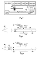
- FIG. 3 shows a schematic overview of components involved in the height measuring system (sensor module) according to the invention.
- the displaying instrument 9 may by way of example comprise: an energy supply unit, a display (LCD), an amplifier (AMP) and filter, and a control unit (MCU), whereby the amplifier, filter and the MCU can be concluded as a decoder.
- the decoder thereby is fed with sensed signals collected by the signal transducer (sensing coil) 15 embracing the magneto-strictive wire 13, as well as with the times of the initial current stimulations (pulse emissions) conducted by the sensor circuitry 17.
- the signals are prompted by the "echoes" of the current pulse emissions.
- the MCU calculates a travel time between sending out the initial pulses of current and the receiving of the signals, from which a distance correlating to the momentary absolute position of the magnet 14 can be derived. Due to the current pulse, Magnet 14 interacts with the magnetic field of the wire 13 and reflects a mechanical wave in the wire 13, which then can be sensed by the sensor coil 15.
- Figure 4 and figure 5 show specific embodiments of the sensor module arrangement.
- Figure 4 an arrangement is shown, in which the magnet 14 is fixed relative to the lower pole section (which comprises the tip 16 and the grip 12), and figure 5 shows an arrangement, in which the magnet 14 is movable relative to the lower pole section according to the height adjustment of the pole.
- contact between the displaying instrument 9 and the sensor circuitry 17 can be established via a contact bar 18 which is sensed by a brush 20 in order to transmit electrical signals, as the upper pole section comprising the sensor circuitry 17 is a moving part.
- a contact bar 18 which is sensed by a brush 20 in order to transmit electrical signals, as the upper pole section comprising the sensor circuitry 17 is a moving part.
- FFC flexible flat cable
Landscapes
- Physics & Mathematics (AREA)
- Engineering & Computer Science (AREA)
- General Physics & Mathematics (AREA)
- Radar, Positioning & Navigation (AREA)
- Remote Sensing (AREA)
- Arrangements For Transmission Of Measured Signals (AREA)
- Measurement Of Length, Angles, Or The Like Using Electric Or Magnetic Means (AREA)
- Length Measuring Devices With Unspecified Measuring Means (AREA)
Priority Applications (3)
| Application Number | Priority Date | Filing Date | Title |
|---|---|---|---|
| EP15183972.7A EP3139127B1 (fr) | 2015-09-04 | 2015-09-04 | Pôle d'arpentage |
| CN201610701872.XA CN106500678A (zh) | 2015-09-04 | 2016-08-22 | 测量杆 |
| US15/256,383 US10113871B2 (en) | 2015-09-04 | 2016-09-02 | Surveying pole |
Applications Claiming Priority (1)
| Application Number | Priority Date | Filing Date | Title |
|---|---|---|---|
| EP15183972.7A EP3139127B1 (fr) | 2015-09-04 | 2015-09-04 | Pôle d'arpentage |
Publications (2)
| Publication Number | Publication Date |
|---|---|
| EP3139127A1 true EP3139127A1 (fr) | 2017-03-08 |
| EP3139127B1 EP3139127B1 (fr) | 2020-02-26 |
Family
ID=54064245
Family Applications (1)
| Application Number | Title | Priority Date | Filing Date |
|---|---|---|---|
| EP15183972.7A Active EP3139127B1 (fr) | 2015-09-04 | 2015-09-04 | Pôle d'arpentage |
Country Status (3)
| Country | Link |
|---|---|
| US (1) | US10113871B2 (fr) |
| EP (1) | EP3139127B1 (fr) |
| CN (1) | CN106500678A (fr) |
Cited By (1)
| Publication number | Priority date | Publication date | Assignee | Title |
|---|---|---|---|---|
| EP3598067A1 (fr) * | 2018-07-16 | 2020-01-22 | Leica Geosystems AG | Pôle de longueur automatique |
Families Citing this family (11)
| Publication number | Priority date | Publication date | Assignee | Title |
|---|---|---|---|---|
| EP3139127B1 (fr) * | 2015-09-04 | 2020-02-26 | Leica Geosystems AG | Pôle d'arpentage |
| EP3182066B1 (fr) * | 2015-12-17 | 2018-07-04 | Leica Geosystems AG | Pôle d'arpentage |
| US10690498B2 (en) * | 2017-05-10 | 2020-06-23 | Trimble, Inc. | Automatic point layout and staking system |
| IT201800006105A1 (it) * | 2018-06-07 | 2019-12-07 | Metodo di ottenimento dei permessi e certificazione di conformità per la costruzione di reti aeree palificate | |
| CN113494902A (zh) * | 2020-04-07 | 2021-10-12 | 海度科技(上海)有限公司 | 一种探测器及距离确定方法 |
| US11608932B2 (en) | 2020-06-24 | 2023-03-21 | Thomas A Drummond | Water-meter extension pole |
| USD1038783S1 (en) * | 2020-11-04 | 2024-08-13 | Laser Elevations, Llc | Electronic grade rod |
| USD1038784S1 (en) * | 2020-11-04 | 2024-08-13 | Laser Elevations, Llc | Active extension for electronic grade rod |
| CN114111643A (zh) * | 2021-12-01 | 2022-03-01 | 成都陵川特种工业有限责任公司 | 可用于定位定向的装备标杆 |
| IT202200021975A1 (it) * | 2022-10-25 | 2024-04-25 | Bearings And Joints S R L | Dispositivo di monitoraggio degli spostamenti tridimensionali particolarmente per strutture civili |
| CN116817877B (zh) * | 2023-08-29 | 2023-12-12 | 中启胶建集团有限公司 | 一种地形勘测的水准测量装置 |
Citations (4)
| Publication number | Priority date | Publication date | Assignee | Title |
|---|---|---|---|---|
| JP2000234933A (ja) | 1999-02-17 | 2000-08-29 | Mutoh Ind Ltd | 測量用ポール |
| EP1130355A2 (fr) | 2000-03-02 | 2001-09-05 | Kabushiki Kaisha Topcon | Cible, système d'arpentage et méthode d'arpentage |
| US7373725B1 (en) | 2005-10-20 | 2008-05-20 | Laserline Mfg., Inc. | Surveying systems and methods for detecting and measuring changes in elevation |
| US7788815B2 (en) | 2005-01-18 | 2010-09-07 | Wilkinson & Associates | Prism pole with direct readout |
Family Cites Families (10)
| Publication number | Priority date | Publication date | Assignee | Title |
|---|---|---|---|---|
| US6502321B1 (en) * | 2000-08-25 | 2003-01-07 | Crain Enterprises, Inc. | Pole section for surveying equipment |
| US6688012B1 (en) * | 2000-08-25 | 2004-02-10 | Crain Enterprises, Inc. | Surveying pole with telescoping sections |
| US8125379B2 (en) * | 2008-04-28 | 2012-02-28 | Trimble Navigation Limited | Position measurement results by a surveying device using a tilt sensor |
| EP2431708A1 (fr) * | 2010-09-16 | 2012-03-21 | Leica Geosystems AG | Système de mesure géodésique doté d'une caméra intégrée dans une unité de télécommande |
| US8230609B1 (en) * | 2010-11-30 | 2012-07-31 | Cook-Sanders Associates, Inc. | Survey pole positioning system |
| EP2722647A1 (fr) * | 2012-10-18 | 2014-04-23 | Leica Geosystems AG | Système de sondage et procédé |
| EP2787321B1 (fr) * | 2013-04-05 | 2015-09-16 | Leica Geosystems AG | Détermination de surface d'objets à l'aide de la détermination d'un seul point précis géodésique et du balayage |
| EP2801841B1 (fr) * | 2013-05-10 | 2018-07-04 | Leica Geosystems AG | Appareil de suivi laser comprenant une unité d'enregistrement d'une cible pour le pistage d'une cible et une détection d'orientation |
| CN204064297U (zh) * | 2014-07-02 | 2014-12-31 | 刘雁春 | 多功能复合测量杆 |
| EP3139127B1 (fr) * | 2015-09-04 | 2020-02-26 | Leica Geosystems AG | Pôle d'arpentage |
-
2015
- 2015-09-04 EP EP15183972.7A patent/EP3139127B1/fr active Active
-
2016
- 2016-08-22 CN CN201610701872.XA patent/CN106500678A/zh active Pending
- 2016-09-02 US US15/256,383 patent/US10113871B2/en active Active
Patent Citations (4)
| Publication number | Priority date | Publication date | Assignee | Title |
|---|---|---|---|---|
| JP2000234933A (ja) | 1999-02-17 | 2000-08-29 | Mutoh Ind Ltd | 測量用ポール |
| EP1130355A2 (fr) | 2000-03-02 | 2001-09-05 | Kabushiki Kaisha Topcon | Cible, système d'arpentage et méthode d'arpentage |
| US7788815B2 (en) | 2005-01-18 | 2010-09-07 | Wilkinson & Associates | Prism pole with direct readout |
| US7373725B1 (en) | 2005-10-20 | 2008-05-20 | Laserline Mfg., Inc. | Surveying systems and methods for detecting and measuring changes in elevation |
Cited By (2)
| Publication number | Priority date | Publication date | Assignee | Title |
|---|---|---|---|---|
| EP3598067A1 (fr) * | 2018-07-16 | 2020-01-22 | Leica Geosystems AG | Pôle de longueur automatique |
| US11703328B2 (en) | 2018-07-16 | 2023-07-18 | Leica Geosystems Ag | Auto-length pole |
Also Published As
| Publication number | Publication date |
|---|---|
| EP3139127B1 (fr) | 2020-02-26 |
| CN106500678A (zh) | 2017-03-15 |
| US20170067740A1 (en) | 2017-03-09 |
| US10113871B2 (en) | 2018-10-30 |
Similar Documents
| Publication | Publication Date | Title |
|---|---|---|
| EP3139127B1 (fr) | Pôle d'arpentage | |
| EP3182066B1 (fr) | Pôle d'arpentage | |
| US11988798B1 (en) | Buried utility marker devices, systems, and methods | |
| US12158232B1 (en) | Pipe inspection and/or mapping camera heads, systems, and methods | |
| EP3555674B1 (fr) | Systèmes et procédés de marquage, de localisation et d'affichage virtuel par voie électronique de réseaux publics enterrés | |
| AU2005293553B2 (en) | Geodesic position determining system | |
| US10809408B1 (en) | Dual sensed locating systems and methods | |
| US8970207B2 (en) | Device for measuring drill bit displacement | |
| CN110726403B (zh) | 自动调节长度的杆 | |
| EP3427331A1 (fr) | Localisateurs de lignes présentant des structures support rétractables et leurs applications | |
| US11187761B1 (en) | Three-axis measurement modules and sensing methods | |
| CN106512373B (zh) | 一种跳远测试装置及跳远成绩评估装置 | |
| CN104154856A (zh) | 电子标志定位器系统和方法 | |
| KR20170130809A (ko) | 레이저 거리계와 기울기 센서를 이용한 측정장치 및 측정방법 | |
| US20120097843A1 (en) | Photoelectric encoder and photoelectric encoder system | |
| EP3534185B1 (fr) | Équipement de localisation | |
| JP2000234933A (ja) | 測量用ポール | |
| KR102191188B1 (ko) | 측량장치 | |
| US20240319398A1 (en) | Pole mounted locator | |
| KR101949326B1 (ko) | 레벨 측정용 디지탈 스타프 | |
| JP2008096316A (ja) | 電磁波測定システム | |
| JP2015042943A (ja) | 傾斜測定装置 |
Legal Events
| Date | Code | Title | Description |
|---|---|---|---|
| PUAI | Public reference made under article 153(3) epc to a published international application that has entered the european phase |
Free format text: ORIGINAL CODE: 0009012 |
|
| STAA | Information on the status of an ep patent application or granted ep patent |
Free format text: STATUS: THE APPLICATION HAS BEEN PUBLISHED |
|
| AK | Designated contracting states |
Kind code of ref document: A1 Designated state(s): AL AT BE BG CH CY CZ DE DK EE ES FI FR GB GR HR HU IE IS IT LI LT LU LV MC MK MT NL NO PL PT RO RS SE SI SK SM TR |
|
| AX | Request for extension of the european patent |
Extension state: BA ME |
|
| STAA | Information on the status of an ep patent application or granted ep patent |
Free format text: STATUS: REQUEST FOR EXAMINATION WAS MADE |
|
| 17P | Request for examination filed |
Effective date: 20170906 |
|
| RBV | Designated contracting states (corrected) |
Designated state(s): AL AT BE BG CH CY CZ DE DK EE ES FI FR GB GR HR HU IE IS IT LI LT LU LV MC MK MT NL NO PL PT RO RS SE SI SK SM TR |
|
| GRAP | Despatch of communication of intention to grant a patent |
Free format text: ORIGINAL CODE: EPIDOSNIGR1 |
|
| STAA | Information on the status of an ep patent application or granted ep patent |
Free format text: STATUS: GRANT OF PATENT IS INTENDED |
|
| RIN1 | Information on inventor provided before grant (corrected) |
Inventor name: HUANG, ZHEN Inventor name: ANG, SIANG CHIEN Inventor name: GE, XI DONG SHAWN Inventor name: PAN, JIAN PENG |
|
| INTG | Intention to grant announced |
Effective date: 20191030 |
|
| RIN1 | Information on inventor provided before grant (corrected) |
Inventor name: GE, XI DONG SHAWN Inventor name: HUANG, ZHEN Inventor name: PAN, JIAN PENG Inventor name: ANG, SIANG CHIEN |
|
| GRAS | Grant fee paid |
Free format text: ORIGINAL CODE: EPIDOSNIGR3 |
|
| GRAA | (expected) grant |
Free format text: ORIGINAL CODE: 0009210 |
|
| STAA | Information on the status of an ep patent application or granted ep patent |
Free format text: STATUS: THE PATENT HAS BEEN GRANTED |
|
| AK | Designated contracting states |
Kind code of ref document: B1 Designated state(s): AL AT BE BG CH CY CZ DE DK EE ES FI FR GB GR HR HU IE IS IT LI LT LU LV MC MK MT NL NO PL PT RO RS SE SI SK SM TR |
|
| REG | Reference to a national code |
Ref country code: GB Ref legal event code: FG4D |
|
| REG | Reference to a national code |
Ref country code: CH Ref legal event code: EP |
|
| REG | Reference to a national code |
Ref country code: AT Ref legal event code: REF Ref document number: 1238173 Country of ref document: AT Kind code of ref document: T Effective date: 20200315 |
|
| REG | Reference to a national code |
Ref country code: IE Ref legal event code: FG4D |
|
| REG | Reference to a national code |
Ref country code: DE Ref legal event code: R096 Ref document number: 602015047621 Country of ref document: DE |
|
| REG | Reference to a national code |
Ref country code: CH Ref legal event code: NV Representative=s name: KAMINSKI HARMANN PATENTANWAELTE AG, LI |
|
| REG | Reference to a national code |
Ref country code: NL Ref legal event code: FP |
|
| REG | Reference to a national code |
Ref country code: SE Ref legal event code: TRGR |
|
| PG25 | Lapsed in a contracting state [announced via postgrant information from national office to epo] |
Ref country code: NO Free format text: LAPSE BECAUSE OF FAILURE TO SUBMIT A TRANSLATION OF THE DESCRIPTION OR TO PAY THE FEE WITHIN THE PRESCRIBED TIME-LIMIT Effective date: 20200526 Ref country code: FI Free format text: LAPSE BECAUSE OF FAILURE TO SUBMIT A TRANSLATION OF THE DESCRIPTION OR TO PAY THE FEE WITHIN THE PRESCRIBED TIME-LIMIT Effective date: 20200226 Ref country code: RS Free format text: LAPSE BECAUSE OF FAILURE TO SUBMIT A TRANSLATION OF THE DESCRIPTION OR TO PAY THE FEE WITHIN THE PRESCRIBED TIME-LIMIT Effective date: 20200226 |
|
| REG | Reference to a national code |
Ref country code: LT Ref legal event code: MG4D |
|
| PG25 | Lapsed in a contracting state [announced via postgrant information from national office to epo] |
Ref country code: IS Free format text: LAPSE BECAUSE OF FAILURE TO SUBMIT A TRANSLATION OF THE DESCRIPTION OR TO PAY THE FEE WITHIN THE PRESCRIBED TIME-LIMIT Effective date: 20200626 Ref country code: GR Free format text: LAPSE BECAUSE OF FAILURE TO SUBMIT A TRANSLATION OF THE DESCRIPTION OR TO PAY THE FEE WITHIN THE PRESCRIBED TIME-LIMIT Effective date: 20200527 Ref country code: HR Free format text: LAPSE BECAUSE OF FAILURE TO SUBMIT A TRANSLATION OF THE DESCRIPTION OR TO PAY THE FEE WITHIN THE PRESCRIBED TIME-LIMIT Effective date: 20200226 Ref country code: LV Free format text: LAPSE BECAUSE OF FAILURE TO SUBMIT A TRANSLATION OF THE DESCRIPTION OR TO PAY THE FEE WITHIN THE PRESCRIBED TIME-LIMIT Effective date: 20200226 Ref country code: BG Free format text: LAPSE BECAUSE OF FAILURE TO SUBMIT A TRANSLATION OF THE DESCRIPTION OR TO PAY THE FEE WITHIN THE PRESCRIBED TIME-LIMIT Effective date: 20200526 |
|
| PG25 | Lapsed in a contracting state [announced via postgrant information from national office to epo] |
Ref country code: PT Free format text: LAPSE BECAUSE OF FAILURE TO SUBMIT A TRANSLATION OF THE DESCRIPTION OR TO PAY THE FEE WITHIN THE PRESCRIBED TIME-LIMIT Effective date: 20200719 Ref country code: DK Free format text: LAPSE BECAUSE OF FAILURE TO SUBMIT A TRANSLATION OF THE DESCRIPTION OR TO PAY THE FEE WITHIN THE PRESCRIBED TIME-LIMIT Effective date: 20200226 Ref country code: SM Free format text: LAPSE BECAUSE OF FAILURE TO SUBMIT A TRANSLATION OF THE DESCRIPTION OR TO PAY THE FEE WITHIN THE PRESCRIBED TIME-LIMIT Effective date: 20200226 Ref country code: EE Free format text: LAPSE BECAUSE OF FAILURE TO SUBMIT A TRANSLATION OF THE DESCRIPTION OR TO PAY THE FEE WITHIN THE PRESCRIBED TIME-LIMIT Effective date: 20200226 Ref country code: ES Free format text: LAPSE BECAUSE OF FAILURE TO SUBMIT A TRANSLATION OF THE DESCRIPTION OR TO PAY THE FEE WITHIN THE PRESCRIBED TIME-LIMIT Effective date: 20200226 Ref country code: LT Free format text: LAPSE BECAUSE OF FAILURE TO SUBMIT A TRANSLATION OF THE DESCRIPTION OR TO PAY THE FEE WITHIN THE PRESCRIBED TIME-LIMIT Effective date: 20200226 Ref country code: RO Free format text: LAPSE BECAUSE OF FAILURE TO SUBMIT A TRANSLATION OF THE DESCRIPTION OR TO PAY THE FEE WITHIN THE PRESCRIBED TIME-LIMIT Effective date: 20200226 Ref country code: CZ Free format text: LAPSE BECAUSE OF FAILURE TO SUBMIT A TRANSLATION OF THE DESCRIPTION OR TO PAY THE FEE WITHIN THE PRESCRIBED TIME-LIMIT Effective date: 20200226 Ref country code: SK Free format text: LAPSE BECAUSE OF FAILURE TO SUBMIT A TRANSLATION OF THE DESCRIPTION OR TO PAY THE FEE WITHIN THE PRESCRIBED TIME-LIMIT Effective date: 20200226 |
|
| REG | Reference to a national code |
Ref country code: AT Ref legal event code: MK05 Ref document number: 1238173 Country of ref document: AT Kind code of ref document: T Effective date: 20200226 |
|
| REG | Reference to a national code |
Ref country code: DE Ref legal event code: R097 Ref document number: 602015047621 Country of ref document: DE |
|
| PLBE | No opposition filed within time limit |
Free format text: ORIGINAL CODE: 0009261 |
|
| STAA | Information on the status of an ep patent application or granted ep patent |
Free format text: STATUS: NO OPPOSITION FILED WITHIN TIME LIMIT |
|
| PG25 | Lapsed in a contracting state [announced via postgrant information from national office to epo] |
Ref country code: IT Free format text: LAPSE BECAUSE OF FAILURE TO SUBMIT A TRANSLATION OF THE DESCRIPTION OR TO PAY THE FEE WITHIN THE PRESCRIBED TIME-LIMIT Effective date: 20200226 Ref country code: AT Free format text: LAPSE BECAUSE OF FAILURE TO SUBMIT A TRANSLATION OF THE DESCRIPTION OR TO PAY THE FEE WITHIN THE PRESCRIBED TIME-LIMIT Effective date: 20200226 |
|
| 26N | No opposition filed |
Effective date: 20201127 |
|
| PG25 | Lapsed in a contracting state [announced via postgrant information from national office to epo] |
Ref country code: SI Free format text: LAPSE BECAUSE OF FAILURE TO SUBMIT A TRANSLATION OF THE DESCRIPTION OR TO PAY THE FEE WITHIN THE PRESCRIBED TIME-LIMIT Effective date: 20200226 Ref country code: PL Free format text: LAPSE BECAUSE OF FAILURE TO SUBMIT A TRANSLATION OF THE DESCRIPTION OR TO PAY THE FEE WITHIN THE PRESCRIBED TIME-LIMIT Effective date: 20200226 |
|
| PG25 | Lapsed in a contracting state [announced via postgrant information from national office to epo] |
Ref country code: MC Free format text: LAPSE BECAUSE OF FAILURE TO SUBMIT A TRANSLATION OF THE DESCRIPTION OR TO PAY THE FEE WITHIN THE PRESCRIBED TIME-LIMIT Effective date: 20200226 |
|
| REG | Reference to a national code |
Ref country code: NL Ref legal event code: MM Effective date: 20201001 |
|
| REG | Reference to a national code |
Ref country code: BE Ref legal event code: MM Effective date: 20200930 |
|
| PG25 | Lapsed in a contracting state [announced via postgrant information from national office to epo] |
Ref country code: NL Free format text: LAPSE BECAUSE OF NON-PAYMENT OF DUE FEES Effective date: 20201001 Ref country code: LU Free format text: LAPSE BECAUSE OF NON-PAYMENT OF DUE FEES Effective date: 20200904 |
|
| PG25 | Lapsed in a contracting state [announced via postgrant information from national office to epo] |
Ref country code: SE Free format text: LAPSE BECAUSE OF NON-PAYMENT OF DUE FEES Effective date: 20200905 Ref country code: IE Free format text: LAPSE BECAUSE OF NON-PAYMENT OF DUE FEES Effective date: 20200904 Ref country code: BE Free format text: LAPSE BECAUSE OF NON-PAYMENT OF DUE FEES Effective date: 20200930 |
|
| REG | Reference to a national code |
Ref country code: SE Ref legal event code: EUG |
|
| PG25 | Lapsed in a contracting state [announced via postgrant information from national office to epo] |
Ref country code: TR Free format text: LAPSE BECAUSE OF FAILURE TO SUBMIT A TRANSLATION OF THE DESCRIPTION OR TO PAY THE FEE WITHIN THE PRESCRIBED TIME-LIMIT Effective date: 20200226 Ref country code: MT Free format text: LAPSE BECAUSE OF FAILURE TO SUBMIT A TRANSLATION OF THE DESCRIPTION OR TO PAY THE FEE WITHIN THE PRESCRIBED TIME-LIMIT Effective date: 20200226 Ref country code: CY Free format text: LAPSE BECAUSE OF FAILURE TO SUBMIT A TRANSLATION OF THE DESCRIPTION OR TO PAY THE FEE WITHIN THE PRESCRIBED TIME-LIMIT Effective date: 20200226 |
|
| PG25 | Lapsed in a contracting state [announced via postgrant information from national office to epo] |
Ref country code: MK Free format text: LAPSE BECAUSE OF FAILURE TO SUBMIT A TRANSLATION OF THE DESCRIPTION OR TO PAY THE FEE WITHIN THE PRESCRIBED TIME-LIMIT Effective date: 20200226 Ref country code: AL Free format text: LAPSE BECAUSE OF FAILURE TO SUBMIT A TRANSLATION OF THE DESCRIPTION OR TO PAY THE FEE WITHIN THE PRESCRIBED TIME-LIMIT Effective date: 20200226 |
|
| REG | Reference to a national code |
Ref country code: CH Ref legal event code: U11 Free format text: ST27 STATUS EVENT CODE: U-0-0-U10-U11 (AS PROVIDED BY THE NATIONAL OFFICE) Effective date: 20251001 |
|
| PGFP | Annual fee paid to national office [announced via postgrant information from national office to epo] |
Ref country code: DE Payment date: 20250919 Year of fee payment: 11 |
|
| PGFP | Annual fee paid to national office [announced via postgrant information from national office to epo] |
Ref country code: GB Payment date: 20250919 Year of fee payment: 11 |
|
| PGFP | Annual fee paid to national office [announced via postgrant information from national office to epo] |
Ref country code: FR Payment date: 20250922 Year of fee payment: 11 |
|
| PGFP | Annual fee paid to national office [announced via postgrant information from national office to epo] |
Ref country code: CH Payment date: 20251001 Year of fee payment: 11 |