EP3139176A2 - Motorsteuerungsverfahren und -system - Google Patents
Motorsteuerungsverfahren und -system Download PDFInfo
- Publication number
- EP3139176A2 EP3139176A2 EP16165116.1A EP16165116A EP3139176A2 EP 3139176 A2 EP3139176 A2 EP 3139176A2 EP 16165116 A EP16165116 A EP 16165116A EP 3139176 A2 EP3139176 A2 EP 3139176A2
- Authority
- EP
- European Patent Office
- Prior art keywords
- motor
- hall sensors
- controller
- value
- rpm
- Prior art date
- Legal status (The legal status is an assumption and is not a legal conclusion. Google has not performed a legal analysis and makes no representation as to the accuracy of the status listed.)
- Withdrawn
Links
Images


Classifications
-
- H—ELECTRICITY
- H02—GENERATION; CONVERSION OR DISTRIBUTION OF ELECTRIC POWER
- H02P—CONTROL OR REGULATION OF ELECTRIC MOTORS, ELECTRIC GENERATORS OR DYNAMO-ELECTRIC CONVERTERS; CONTROLLING TRANSFORMERS, REACTORS OR CHOKE COILS
- H02P6/00—Arrangements for controlling synchronous motors or other dynamo-electric motors using electronic commutation dependent on the rotor position; Electronic commutators therefor
- H02P6/12—Monitoring commutation; Providing indication of commutation failure
-
- H—ELECTRICITY
- H02—GENERATION; CONVERSION OR DISTRIBUTION OF ELECTRIC POWER
- H02P—CONTROL OR REGULATION OF ELECTRIC MOTORS, ELECTRIC GENERATORS OR DYNAMO-ELECTRIC CONVERTERS; CONTROLLING TRANSFORMERS, REACTORS OR CHOKE COILS
- H02P21/00—Arrangements or methods for the control of electric machines by vector control, e.g. by control of field orientation
- H02P21/22—Current control, e.g. using a current control loop
-
- G—PHYSICS
- G01—MEASURING; TESTING
- G01D—MEASURING NOT SPECIALLY ADAPTED FOR A SPECIFIC VARIABLE; ARRANGEMENTS FOR MEASURING TWO OR MORE VARIABLES NOT COVERED IN A SINGLE OTHER SUBCLASS; TARIFF METERING APPARATUS; MEASURING OR TESTING NOT OTHERWISE PROVIDED FOR
- G01D5/00—Mechanical means for transferring the output of a sensing member; Means for converting the output of a sensing member to another variable where the form or nature of the sensing member does not constrain the means for converting; Transducers not specially adapted for a specific variable
- G01D5/12—Mechanical means for transferring the output of a sensing member; Means for converting the output of a sensing member to another variable where the form or nature of the sensing member does not constrain the means for converting; Transducers not specially adapted for a specific variable using electric or magnetic means
- G01D5/14—Mechanical means for transferring the output of a sensing member; Means for converting the output of a sensing member to another variable where the form or nature of the sensing member does not constrain the means for converting; Transducers not specially adapted for a specific variable using electric or magnetic means influencing the magnitude of a current or voltage
- G01D5/142—Mechanical means for transferring the output of a sensing member; Means for converting the output of a sensing member to another variable where the form or nature of the sensing member does not constrain the means for converting; Transducers not specially adapted for a specific variable using electric or magnetic means influencing the magnitude of a current or voltage using Hall-effect devices
- G01D5/145—Mechanical means for transferring the output of a sensing member; Means for converting the output of a sensing member to another variable where the form or nature of the sensing member does not constrain the means for converting; Transducers not specially adapted for a specific variable using electric or magnetic means influencing the magnitude of a current or voltage using Hall-effect devices influenced by the relative movement between the Hall device and magnetic fields
-
- G—PHYSICS
- G01—MEASURING; TESTING
- G01D—MEASURING NOT SPECIALLY ADAPTED FOR A SPECIFIC VARIABLE; ARRANGEMENTS FOR MEASURING TWO OR MORE VARIABLES NOT COVERED IN A SINGLE OTHER SUBCLASS; TARIFF METERING APPARATUS; MEASURING OR TESTING NOT OTHERWISE PROVIDED FOR
- G01D5/00—Mechanical means for transferring the output of a sensing member; Means for converting the output of a sensing member to another variable where the form or nature of the sensing member does not constrain the means for converting; Transducers not specially adapted for a specific variable
- G01D5/12—Mechanical means for transferring the output of a sensing member; Means for converting the output of a sensing member to another variable where the form or nature of the sensing member does not constrain the means for converting; Transducers not specially adapted for a specific variable using electric or magnetic means
- G01D5/244—Mechanical means for transferring the output of a sensing member; Means for converting the output of a sensing member to another variable where the form or nature of the sensing member does not constrain the means for converting; Transducers not specially adapted for a specific variable using electric or magnetic means influencing characteristics of pulses or pulse trains; generating pulses or pulse trains
- G01D5/24457—Failure detection
- G01D5/24461—Failure detection by redundancy or plausibility
-
- G—PHYSICS
- G01—MEASURING; TESTING
- G01P—MEASURING LINEAR OR ANGULAR SPEED, ACCELERATION, DECELERATION, OR SHOCK; INDICATING PRESENCE, ABSENCE, OR DIRECTION, OF MOVEMENT
- G01P21/00—Testing or calibrating of apparatus or devices covered by the preceding groups
- G01P21/02—Testing or calibrating of apparatus or devices covered by the preceding groups of speedometers
-
- G—PHYSICS
- G01—MEASURING; TESTING
- G01P—MEASURING LINEAR OR ANGULAR SPEED, ACCELERATION, DECELERATION, OR SHOCK; INDICATING PRESENCE, ABSENCE, OR DIRECTION, OF MOVEMENT
- G01P3/00—Measuring linear or angular speed; Measuring differences of linear or angular speeds
- G01P3/42—Devices characterised by the use of electric or magnetic means
- G01P3/44—Devices characterised by the use of electric or magnetic means for measuring angular speed
- G01P3/48—Devices characterised by the use of electric or magnetic means for measuring angular speed by measuring frequency of generated current or voltage
- G01P3/481—Devices characterised by the use of electric or magnetic means for measuring angular speed by measuring frequency of generated current or voltage of pulse signals
-
- H—ELECTRICITY
- H02—GENERATION; CONVERSION OR DISTRIBUTION OF ELECTRIC POWER
- H02P—CONTROL OR REGULATION OF ELECTRIC MOTORS, ELECTRIC GENERATORS OR DYNAMO-ELECTRIC CONVERTERS; CONTROLLING TRANSFORMERS, REACTORS OR CHOKE COILS
- H02P6/00—Arrangements for controlling synchronous motors or other dynamo-electric motors using electronic commutation dependent on the rotor position; Electronic commutators therefor
- H02P6/06—Arrangements for speed regulation of a single motor wherein the motor speed is measured and compared with a given physical value so as to adjust the motor speed
-
- H—ELECTRICITY
- H02—GENERATION; CONVERSION OR DISTRIBUTION OF ELECTRIC POWER
- H02P—CONTROL OR REGULATION OF ELECTRIC MOTORS, ELECTRIC GENERATORS OR DYNAMO-ELECTRIC CONVERTERS; CONTROLLING TRANSFORMERS, REACTORS OR CHOKE COILS
- H02P6/00—Arrangements for controlling synchronous motors or other dynamo-electric motors using electronic commutation dependent on the rotor position; Electronic commutators therefor
- H02P6/14—Electronic commutators
- H02P6/16—Circuit arrangements for detecting position
- H02P6/17—Circuit arrangements for detecting position and for generating speed information
Definitions
- a typical 3-phase motor includes a 3-phase coil installed on a stator and a permanent magnet magnetized on a rotor.
- a driving circuit for the 3-phase motor causes current to flow through respective phases of coils on the stator, and the rotor of the motor is rotated by a magnetic field based on the current supplied from the driving circuit.
- To continuously rotate the rotor of the motor in one direction the position of the rotor must be detected, and switching elements for switching the directions of currents flowing through the respective phases of the coils must be sequentially turned on and off based on the detected position of the rotor.
- the accurate position of the rotor is detected using three Hall signals, which are formed by the magnetic field of the rotor and have a phase difference of 120°.
- the three Hall signals are detected by Hall detectors such as Hall sensors or Hall Integrated Circuits (ICs). Therefore, the motor and the driving circuit thereof are driven or operated when the position information of the rotor is obtained from the Hall sensors.
- Hall sensors are known to easily break down and also vary due to external factors, such as temperature, thus resulting in the malfunction of the motor.
- the present invention provides a motor control method, which may determine a failure individual Hall sensors disposed within a motor, and may suitably operate the motor even when the motor fails, based on such determination.
- the present invention provides a motor control method that may include recognizing, by a controller, a driving signal for a motor; when the controller recognizes the driving signal; determining, by the controller, failure of multiple Hall sensors disposed within the motor, based on signals detected by the multiple Hall sensors; and when a failure of the Hall sensors is determined, identifying, by the controller, a faulty Hall sensor from among the multiple Hall sensors by analyzing respective frequencies of the signals detected by the multiple Hall sensors.
- the detection of the failure of the multiple Hall sensors may include, when the controller recognizes the driving signal, receiving, by the controller, the detected signals from the multiple Hall sensors disposed within the motor, and when the multiple detected signals are identical to each other, determining, by the controller, a failure of one or more of the multiple Hall sensors.
- the motor control method may further include, after determining a failure of the multiple Hall sensors, when the multiple Hall sensors disposed within the motor are determined to be normal (e.g., no failure detected), calculating, by the controller, a current difference value that is a difference between a current command value, generated by driving of the motor, and a motor control current value; and when the calculated current difference value is greater than a preset current difference reference value, stopping, by the controller, driving of the motor.
- the motor control method may further include, after calculating the current difference value, when the current difference value is less than or equal to the preset current difference reference value, comparing, by the controller, a first elapsed time with a preset first reference time, wherein the first elapsed time may be a period of time elapsed from a time at which the driving signal for the motor is recognized; when the first elapsed time is greater than the first reference time, calculating, by the controller, a rotational speed (RPM) difference value that is a difference between an RPM command value, generated by driving of the motor, and an RPM value of the motor; and when the calculated RPM difference value is greater than a preset RPM difference reference value, identifying, by the controller, a faulty Hall sensor.
- RPM rotational speed
- the motor control method may further include, after calculating the RPM difference value, when the calculated RPM difference value is less than or equal to the preset RPM difference reference value, determining, by the controller, the Hall sensors in the motor to be in a normal state.
- the identification of the faulty Hall sensor may include increasing, by the controller, RPM of a stator of the motor to a preset target RPM value; after the RPM of the stator of the motor has reached the target RPM value, receiving, by the controller, frequency value signals detected by respective Hall sensors in the motor; calculating, by the controller, frequency difference values that are differences between the received frequency values of respective Hall sensors and a frequency reference value; and when the calculated frequency difference values for respective Hall sensors are equal to or greater than a preset frequency difference reference value, determining, by the controller, the corresponding Hall sensors to be in a faulty state.
- the motor control method may further include, after calculating the frequency difference values, when the calculated frequency difference values for respective Hall sensors are less than the preset frequency difference reference value, comparing second elapsed times with a preset second reference time, wherein the second elapsed times may be periods of time elapsed from times at which the calculated frequency difference values for respective Hall sensors are less than the frequency difference reference value; and when the second elapsed times are less than or equal to the second reference time, determining, by the controller, the corresponding Hall sensors to be in a faulty state.
- the motor control method may further include, after comparing with the second reference time, when the second elapsed times are greater than the second reference time, determining, by the controller, the corresponding Hall sensors to be in a normal state.
- the motor control method may further include, after identifying the faulty Hall sensor, when a Hall sensor in a normal state is present in the motor, receiving, by the controller, a signal from the Hall sensor determined to be in a normal state; when the signal from the Hall sensor, received by the controller, is varied, calculating, by the controller, RPM of the motor and a position of a rotor using variation; and calculating, by the controller, a motor control current value using the RPM of the motor and the position of the rotor.
- the motor control method may further include, after calculating the motor control current value, calculating, by the controller, a current difference value that is a difference between a preset current reference value and the motor control current value; and when the calculated current difference value is greater than a preset current difference reference value, stopping, by the controller, driving of the motor.
- the present invention provides a motor control method, wherein, when a controller recognizes a driving signal for a motor, the controller may be configured to determine a failure of multiple Hall sensors indisposed within the motor, based on signals detected by the multiple Hall sensors, and identify a faulty Hall sensor from among the multiple Hall sensors by analyzing respective frequencies of the signals detected by the Hall sensors.
- vehicle or “vehicular” or other similar term as used herein is inclusive of motor vehicles in general such as passenger automobiles including sports utility vehicles (SUV), buses, trucks, various commercial vehicles, watercraft including a variety of boats and ships, aircraft, and the like, and includes hybrid vehicles, electric vehicles, combustion, plug-in hybrid electric vehicles, hydrogen-powered vehicles and other alternative fuel vehicles (e.g. fuels derived from resources other than petroleum).
- motor vehicles in general such as passenger automobiles including sports utility vehicles (SUV), buses, trucks, various commercial vehicles, watercraft including a variety of boats and ships, aircraft, and the like, and includes hybrid vehicles, electric vehicles, combustion, plug-in hybrid electric vehicles, hydrogen-powered vehicles and other alternative fuel vehicles (e.g. fuels derived from resources other than petroleum).
- SUV sports utility vehicles
- plug-in hybrid electric vehicles e.g. fuels derived from resources other than petroleum
- controller/control unit refers to a hardware device that includes a memory and a processor.
- the memory is configured to store the modules and the processor is specifically configured to execute said modules to perform one or more processes which are described further below.
- sensors are provided to detect the position and speed of a rotor equipped with a permanent magnet.
- a resolver sensor having high precision may be used, but in motors used in typical pumps, compressors, or blowers, cheaper Hall sensors may be used.
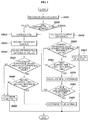
- Hall sensor signals are disadvantageous in that it may be difficult to determine whether sensors are abnormal using only the output signals of the sensors. Therefore, referring to FIG. 1 , the present invention presents a motor control method capable of detecting failures in Hall sensors in the motor.
- the motor control method may include recognizing, by a controller, a driving signal for a motor (S100); when the driving signal is recognized, determining, by the controller, a failure of multiple Hall sensors indisposed within the motor, using signals detected by the Hall sensors (S200); and when the failure of the Hall sensors is detected, analyzing, by the controller, respective frequencies of the signals detected by the multiple Hall sensors, thus identifying a faulty Hall sensor from among the multiple Hall sensors (S300).
- the controller when the driving signal for the motor is recognized in the state in which the motor has stopped, the controller may be configured to detect whether a failure of the multiple Hall sensors has occurred. The determination is intended to determine whether the Hall sensors in the motor are normal or abnormal (e.g., whether a failure has occurred). When all of the Hall sensors in the motor are abnormal, a separate fault diagnosis in the respective Hall sensors in the motor may be omitted. Thus, before the identification step S700, this step S200 may be performed, and a separate motor control may be performed when all of the Hall sensors in the motor are normal (e.g., operating without failure).
- a failure of the Hall sensors may also be determined using the rotational speed (revolutions per minute: RPM) of the motor or variation in current generated by the driving of the motor.
- RPM rotational speed
- the present invention presents a method by which, when multiple Hall sensors disposed within the motor transmit the same detected signal, a controller may be configured to determine a failure in the Hall sensors.
- the Hall sensors may be configured to transmit various signals based on the types thereof, but generally may be configured to transmit digital signals. In other words, the Hall sensors may be configured to transmit signals in the form of 0 or 1 or the form of OFF or ON. Therefore, the present invention presents a method of determining whether Hall sensors are faulty using this characteristic.
- signals from the Hall sensors may be digital signals represented by 0 or 1. Therefore, when a motor having three Hall sensors that are generally used is given as an example, sensor signal values obtained when all of the Hall sensors are normal are varied at rotation intervals of 60°. In other words, since the signal values from the Hall sensors are configured, as shown in FIG. 3A , Hall sensors A, B, and C may not transmit the same signal, i.e. a signal of 0 or 1, in the sections of 1 ⁇ 6 of FIGS. 3A-3B under any circumstances. In FIGS. 3A-3B , although the case where the number of Hall sensors is 3 has been illustrated, all Hall sensors may not transmit the same signal even when there are three or more Hall sensors. Therefore, according to the present invention, when none of Hall sensors disposed within the motor transmit the same signal, the Hall sensors in the motor may be determined to be normal (e.g., operating without error), and then a subsequent step is performed.
- the current difference value in the present invention may consequently be regarded as a difference between the current command value, which is output by the speed controller as previously stated and the control current value, which is flowing through the three phase motor.
- a larger current difference value indicates that the motor is insufficient performing a function (e.g., function is not accurately performed), and thus separate control may be required.
- the current difference reference value may be a previously set value, stored in a separately provided memory unit or the flash memory unit of the controller. Therefore, the controller may be configured to stop the driving of the motor when the current difference value is greater than the current difference reference value, that is, a difference between an allowable target current and a current actually flowing through the motor.
- the current difference reference value which is a reference value required to stop the motor driving, may be present as various values based on the type of motors and the type of devices in which the motors are used. When the accurate operation of the motor is required, the current difference reference value may be set to a minimal value. When a device in which a wide allowable error range is permitted, the current difference reference value may be set to a greater value.
- the controller may be configured to stop the driving of the motor to maintain safety.
- the controller may be configured to compare a first elapsed time, which is a period of time elapsed from the time at which the driving signal for the motor is recognized, with a preset first reference time, as shown in FIG. 1 ; and when the first elapsed time is greater than the first reference time, calculate an RPM difference value, which is a difference between the RPM command value generated by the driving of the motor and the RPM value of the motor.
- the above-described first reference time comparison step S360 and the RPM difference calculation step S370 may be prepared for secondary diagnosis to prevent a determination error when detecting a failure at the Hall sensor even when all of the Hall sensors are determined to be normal at step S200.
- the current sensor and the 3-phase switching circuit of the motor have been determined to be in a normal state at the step S320 of comparing the current difference value with the preset current difference reference value. Accordingly, when, during the determination of whether an error is present in the operation of the motor, an error in the motor operation is determined to be present, the error may be determined to be an operation error attributable to the Hall sensors in the motor.
- the first reference time may be the maximum time required by the motor to normally perform current control. It may be possible to perform more accurate fault diagnosis when the presence or non-presence of the operation error in the Hall sensors in the motor is determined after the first elapsed time, which is the period of time elapsed from the time at which the driving signal for the motor is recognized, has exceeded the first reference time. Accordingly, the controller may be configured to execute the first reference time comparison step S360, thus providing a margin required by the motor to perform normal current control. Similar to the above-described current difference reference value, the first reference time may be stored in the separately provided memory unit or in the flash memory unit of the controller.
- an RPM difference value which is a difference between the RPM command value and the RPM value of the motor, may be calculated.
- the RPM command value may have various values based on the output desired by the user to be obtained using the motor.
- the RPM of the motor may be considered to detect a failure of the Hall sensors in the motor since detection of the RPM is a function of the Hall sensors to detect the speed of the rotor. Therefore, when a fault in the Hall sensors is detected in the motor, the speed of the rotor may not be accurately detected, and thus, using the rotating speed of the motor, a failure of the Hall sensors in the motor may be determined.
- the controller when the calculated RPM difference value is less than or equal to the preset RPM difference reference value, the controller may be configured to determine that the Hall sensors in the motor are in a normal state.
- the RPM difference reference value indicates an error value falling within a range in which an error is not caused in the operation of the motor, similar to the above-described current difference reference value. Since there is an inevitable difference between the RPM reference value, which is a theoretical value, and the RPM value of the motor, which is an actually measured value, the RPM difference reference value may also be provided to compensate for such a difference.
- the RPM difference reference value may also be present as various values based on the type of motors and the type of devices in which the motors are used, similar to the current difference reference value. Further, similar to the current difference reference value, the RPM difference reference value may also be stored in the separately provided memory unit or the flash memory unit of the controller.
- the controller may be configured to determine that the Hall sensors in the motor are in a normal state.
- the controller may be configured to identify a faulty Hall sensor from among the Hall sensors. This step is identical to the identification step S700 which is performed when Hall sensors are determined to be faulty at the Hall sensor fault determination step S200.
- the method by which the controller determines a failure the Hall sensors may be implemented using various methods, as described above.
- a failure of the Hall sensors may be detected. This corresponds to the reverse case of the above-described normality determination, and corresponds to FIG. 3B .
- FIG. 3B shows that when one of the Hall sensors (e.g. Hall sensor B in FIG. 3B ) fails, the Hall sensor B is incapable of transmitting a signal and will transmit a signal of 0 regardless of the position where the permanent magnet is located.
- FIG. 3B shows that all of Hall sensors A, B, and C transmit signals of 0 in section 1 in the graph of FIG. 3B . Therefore, in the present invention, a failure of the Hall sensors may be determined using the graph of FIG. 3B .
- the controller may be configured to detect that, among the three Hall sensors, Hall sensor B has failed. However, when two or more of the Hall sensors have failed, the Hall sensors may not be distinguished to thus determine which Hall sensor has failed. In particular, when four or more Hall sensors are disposed within the motor, it may be difficult to determine which of the Hall sensors has failed, using only the above-described method. Therefore, when a failure in the Hall sensors is detected, the controller may be configured to identify a faulty Hall sensor from among the Hall sensors (S700).
- the increase in the RPM of the stator of the motor has the same meaning as the increase in the rotational speed of a rotating magnetic field formed in the stator of the motor. Therefore, the controller may be configured to increase the rotational speed of the rotating magnetic field formed in the stator of the motor to synchronize the rotating magnetic field formed by the rotation of the stator with a rotating magnetic field formed by the rotation of the rotor. To derive a precise Hall sensor frequency value, the stator and the rotor of the motor may be rotated by the rotating magnetic fields thereof synchronized with each other to thus increase the RPM of the stator.
- the target RPM value may be an angular velocity, which has the unit of [rad/s], and may be present as various values. However, when the target RPM value is set to an excessively large value, there is concern that the rotor will not be rotated in synchronization with the stator and will be out of phase, and thus the target RPM value may be set to a suitable value within the range of prevention of such a situation.
- the target RPM value may also be stored in the separately provided memory unit or the flash memory unit of the controller.
- the frequency signal reception step S520 may be performed.
- the frequency values detected by the Hall sensors indicate the frequencies of pulse signals formed due to the repetition of signals of 0 or 1 that are transferred to the controller by the Hall sensors. Since the Hall sensors according to the present invention may be configured to transmit digital signals, it may be difficult to consider that the signals themselves have certain frequencies. However, when the stator and the rotor of the motor are continuously rotated at a substantially constant speed in synchronization with each other, the Hall sensors may be configured to periodically transmit the same signals of 0 or 1. Consequently, these signals have the form of pulse signals having a regular period, and thus frequency values may be derived.
- the present frequency signal reception step is intended to individually determine whether all of the Hall sensors provided in the motor are faulty, and thus the frequency values of the respective Hall sensors may be derived.
- the controller may be configured to calculate the frequency difference values, which are differences between the frequency values of the respective Hall sensors and the frequency reference value.
- the frequency reference value denotes a Hall sensor frequency value when the rotor is rotated at the target rotational speed (RPM) value of the rotating magnetic field formed in the stator.
- the frequency reference value which is a value derived based on the period of signals of 0 or 1 detected by the Hall sensors when the Hall sensors are normal, may be obtained using the RPM of the motor or the number of poles of the motor. Generally, as the number of poles of the motor increases, or as the RPM of the motor increases, the period decreases, and thus the frequency reference value may be increased.
- the controller may be configured to compare the frequency difference values with the frequency difference reference value.
- the frequency difference reference value may be the value required to compensate for differences between theoretical values and actually measured values, similar to the above-described current reference value, and may be present as various values based on the types and RPM values of motors. However, for the purpose of precise fault diagnosis of Hall sensors, which corresponds to the object of the present invention, the frequency difference reference value may be set to a smaller value. Further, the frequency difference reference value may also be stored in the separately provided memory unit or the flash memory unit of the controller.
- the controller may be configured to determine the corresponding Hall sensor to be in a faulty (abnormal) state.
- the corresponding Hall sensor since the corresponding Hall sensor does not transfer a signal of 0 or 1 in conformity with the RPM of the motor, the corresponding Hall sensor may be determined to be in a faulty state.
- the controller may be configured to compare second elapsed times, which are periods of time elapsed from the times at which the calculated frequency difference values for respective Hall sensors are less than the frequency difference reference value, with a preset second reference time.
- the fact that the frequency difference values are less than the frequency difference reference value may indicate that the Hall sensors are operating more accurately, and thus the Hall sensors may be determined to be in a normal state.
- the second reference time comparison step S580 may be performed to improve precision in the fault diagnosis of the Hall sensors.
- the second elapsed times denote periods of time elapsed from the times at which the calculated frequency difference values for respective Hall sensors are less than the frequency difference reference value
- failures in the Hall sensors that may occur after the RPM of the motor has reached the target RPM value may be detected at step S580.
- erroneous detection of failures in the Hall sensors may be prevented from being caused by noise signals.
- the frequency difference values may be instantaneously less than the frequency difference reference value due to noise signals. Therefore, at this step, the second reference time may be provided and configured to filter noise that may occur, thus preventing erroneous detection of faults in the Hall sensors.
- the second reference time increases, precision in fault diagnosis of Hall sensors may be further improved.
- the fault diagnosis may be insignificant, and thus the second reference time may be set to a suitable time within a range in which the usage purpose of the motor is satisfied.
- the second reference time may also be stored in the separately provided memory unit or the flash memory unit of the controller, similar to the first reference time.
- the present invention is intended to present a method capable of controlling the motor using this determination even when some Hall sensors are faulty.
- the present invention may more accurately determined which one of the Hall sensors is faulty at the identification step S700. Therefore, after the identification step S700, when any Hall sensor in a normal state is found to be in the motor at step S720 of determining whether any Hall sensor in a normal state is present in the motor, the Hall sensor in the normal state may be used.
- the present invention performs the normal signal reception step S740 of the controller receiving a signal from the Hall sensor determined to be in a normal state; the speed and position calculation step S780 of, when the received Hall sensor signal is varied, the controller calculating the RPM of the motor and the position of the rotor using variation; and the control current calculation step S800 of calculating a motor control current value using the RPM of the motor and the position of the rotor.
- the controller may be configured to selectively receive the signal detected by the Hall sensor determined to be in a normal state at the identification step S700. Since the signals of the Hall sensors determined to be in a faulty state at the identification step S700 are insignificant (e.g., meaningless) signals, the controller may be configured to receive only the signal of the Hall sensor determined to be in a normal state. When there are multiple Hall sensors in a normal state, the controller may be configured to receive all of signals of the multiple Hall sensors without separating the signals to improve precision in motor control.
- the current position of the rotor may be calculated by adding a previous position value to a position variation value obtained by multiplying a current RPM by a time difference between previous and current times. Further, the RPM of the motor may be obtained by differentiating the position value of the rotor when the position value of the rotor is detected. Therefore, when the present method is used, the position of the rotor and the RPM of the motor may be more accurately detected using the normal Hall sensor even when some Hall sensors have failed (are faulty).
- a motor control current required to drive the motor may be calculated using the position and the RPM.
- the motor control current may be calculated using the RPM of the motor, as described above, the motor control current may be more easily calculated when the RPM of the motor calculated at the speed and position calculation step S780 is used.
- speed feedback control which is a typical motor control scheme, may be performed.
- speed feedback control refers to a control method performed when Hall sensors are determined to be normal at the above-described Hall sensor fault determination step S200. Even when all Hall sensors have failed, the motor may be operated in the same manner as that of the normal state using a normal Hall sensor. Therefore, a typical speed feedback control may be used. As described above, when the current difference value is less than or equal to the current difference reference value denotes a situation in which current control is suitably performed, and thus the motor may be driven using the motor control current calculated at the control current calculation step S800.
- the current difference value which is a difference between the motor control current value, calculated at the control current calculation step S800, and a current reference value
- a failure of a current sensor or a 3-phase switching circuit may be determined, and then the controller may be configured to stop the driving of the motor.
- the current reference value and the current difference reference value are identical to the above-described values, respectively.
Landscapes
- Physics & Mathematics (AREA)
- General Physics & Mathematics (AREA)
- Engineering & Computer Science (AREA)
- Power Engineering (AREA)
- Control Of Motors That Do Not Use Commutators (AREA)
- Condensed Matter Physics & Semiconductors (AREA)
Applications Claiming Priority (1)
| Application Number | Priority Date | Filing Date | Title |
|---|---|---|---|
| KR1020150113938A KR101694047B1 (ko) | 2015-08-12 | 2015-08-12 | 모터 제어 방법 |
Publications (2)
| Publication Number | Publication Date |
|---|---|
| EP3139176A2 true EP3139176A2 (de) | 2017-03-08 |
| EP3139176A3 EP3139176A3 (de) | 2017-06-07 |
Family
ID=55806152
Family Applications (1)
| Application Number | Title | Priority Date | Filing Date |
|---|---|---|---|
| EP16165116.1A Withdrawn EP3139176A3 (de) | 2015-08-12 | 2016-04-13 | Motorsteuerungsverfahren und -system |
Country Status (5)
| Country | Link |
|---|---|
| US (1) | US9837945B2 (de) |
| EP (1) | EP3139176A3 (de) |
| JP (1) | JP6664995B2 (de) |
| KR (1) | KR101694047B1 (de) |
| CN (1) | CN106470002B (de) |
Cited By (2)
| Publication number | Priority date | Publication date | Assignee | Title |
|---|---|---|---|---|
| JP2022067556A (ja) * | 2020-10-20 | 2022-05-06 | オークマ株式会社 | エンコーダ異常診断装置 |
| EP4249854A1 (de) * | 2022-03-22 | 2023-09-27 | Delta Electronics, Inc. | Fehlerdiagnosesystem und fehlerdiagnoseverfahren für einen motorcodierer |
Families Citing this family (20)
| Publication number | Priority date | Publication date | Assignee | Title |
|---|---|---|---|---|
| JP6706938B2 (ja) * | 2016-03-18 | 2020-06-10 | ローム株式会社 | モータ駆動装置 |
| CN109286353B (zh) * | 2017-07-21 | 2021-01-19 | 深圳市道通智能航空技术有限公司 | 一种电机控制模式故障检测方法及装置 |
| KR102413372B1 (ko) * | 2017-08-08 | 2022-06-28 | 주식회사 만도 | 차량의 전자식 주차 브레이크 시스템 및 그 제어 방법 |
| KR102588927B1 (ko) * | 2017-12-07 | 2023-10-16 | 현대자동차주식회사 | 모터 제어방법 |
| KR102518183B1 (ko) * | 2017-12-20 | 2023-04-07 | 현대자동차주식회사 | 모터 제어방법 |
| CN109633509B (zh) * | 2018-12-26 | 2021-02-02 | 北京经纬恒润科技股份有限公司 | 电机故障诊断系统、方法及可读存储介质 |
| US20200341444A1 (en) * | 2019-04-24 | 2020-10-29 | Rob Dusseault | Systems and methods for wireless monitoring and control of machinery |
| CA3055662A1 (en) * | 2019-09-16 | 2021-03-16 | Neutron Automotive Controls Inc. | Redundant brushless direct current motor control system and related methods |
| CN112564553A (zh) * | 2019-09-25 | 2021-03-26 | 博泽沃尔兹堡汽车零部件有限公司 | 一种识别带霍尔传感器的电机的方法和装置 |
| CN112576134B (zh) * | 2019-09-30 | 2022-03-18 | 比亚迪股份有限公司 | 车门障碍物的预警方法、装置、设备及存储介质 |
| CN113734239B (zh) * | 2020-05-28 | 2023-08-08 | 比亚迪汽车工业有限公司 | 轨道车辆及其控制方法 |
| CN112014776B (zh) * | 2020-09-11 | 2023-06-27 | 广东美的暖通设备有限公司 | 接线检测方法、磁悬浮压缩机、空调机组和可读存储介质 |
| TWI799744B (zh) * | 2020-10-16 | 2023-04-21 | 達明機器人股份有限公司 | 馬達電流感測器的檢知系統及方法 |
| CN114963952B (zh) * | 2021-02-24 | 2025-12-19 | 广州汽车集团股份有限公司 | 霍尔传感器的故障诊断方法、装置及转向控制系统 |
| CN114485738B (zh) * | 2022-01-06 | 2024-01-12 | 天津中德应用技术大学 | 一种双组霍尔传感器装置及其控制方法 |
| CN114660456B (zh) * | 2022-03-31 | 2025-12-30 | 乐歌人体工学科技股份有限公司 | 用于无刷电机的故障判断方法、装置、控制方法及升降桌 |
| CN116388469A (zh) * | 2023-04-03 | 2023-07-04 | 浙江同舟汽车配件有限公司 | 一种驱动装置及其驱动方法 |
| CN117034121B (zh) * | 2023-08-18 | 2024-09-10 | 南京中旭电子科技有限公司 | 霍尔传感器故障显示方法、装置、设备及存储介质 |
| CN117879446B (zh) * | 2024-01-12 | 2024-06-25 | 南京航空航天大学 | 基于非导通相电流的双凸极电机位置传感器故障诊断方法 |
| KR20250132242A (ko) * | 2024-02-28 | 2025-09-04 | 삼성전자주식회사 | 모터의 상태를 결정하는 방법 및 그 방법을 수행하는 구동 모듈 |
Citations (1)
| Publication number | Priority date | Publication date | Assignee | Title |
|---|---|---|---|---|
| EP2446279B1 (de) * | 2009-06-26 | 2015-04-22 | Mitsubishi Electric Corporation | Vorrichtung zur bestimmung der drehgeschwindigkeit mit fehlerüberwachung |
Family Cites Families (25)
| Publication number | Priority date | Publication date | Assignee | Title |
|---|---|---|---|---|
| DE3524269A1 (de) * | 1985-07-06 | 1987-01-08 | Bosch Gmbh Robert | Verfahren zum erkennen von drehzahlschwankungen einer brennkraftmaschine |
| JPH0888993A (ja) | 1994-09-13 | 1996-04-02 | Matsushita Electric Ind Co Ltd | Dcブラシレスモータの保護方法 |
| JPH08172721A (ja) * | 1994-12-19 | 1996-07-02 | Yamaha Motor Co Ltd | モータ出力系の異常検出装置 |
| KR100237611B1 (ko) * | 1997-01-14 | 2000-01-15 | 이종수 | 엘리베이터의 인버터 이상동작 방지장치 |
| JPH1189272A (ja) * | 1997-09-04 | 1999-03-30 | Daikin Ind Ltd | モータの異常検出装置 |
| JP2001079041A (ja) * | 1999-09-10 | 2001-03-27 | Matsushita Electric Ind Co Ltd | 電動車椅子の異常検出方法 |
| JP2001161089A (ja) * | 1999-11-29 | 2001-06-12 | Nikkiso Co Ltd | 多相電動機の制御装置 |
| JP3968972B2 (ja) * | 2000-08-14 | 2007-08-29 | 日本精工株式会社 | 電動パワーステアリング装置の制御装置 |
| DE10235161A1 (de) * | 2002-08-01 | 2004-02-19 | Robert Bosch Gmbh | Sensor, Steuergerät und Verfahren zur Überwachung wenigstens eines Sensors |
| JP4355189B2 (ja) * | 2003-10-10 | 2009-10-28 | 日本精工株式会社 | 電動パワーステアリング装置の制御装置 |
| JP2006033928A (ja) * | 2004-07-13 | 2006-02-02 | Hitachi Ltd | ブラシレスモータ |
| JP3953491B2 (ja) | 2005-02-03 | 2007-08-08 | 三菱電機エンジニアリング株式会社 | 自動ドアの開閉制御装置 |
| KR101349851B1 (ko) | 2007-10-18 | 2014-01-09 | 엘지전자 주식회사 | 전동기 제어장치 및 그 제어방법 |
| JP5356077B2 (ja) * | 2009-03-16 | 2013-12-04 | 日立オートモティブシステムズ株式会社 | 車両用モータの制御装置 |
| KR101251509B1 (ko) | 2010-12-01 | 2013-04-05 | 기아자동차주식회사 | 하이브리드 자동차의 고장진단장치 및 방법 |
| AU2012215102A1 (en) | 2011-02-08 | 2013-08-22 | Institut National De La Recherche Scientifique | Catalysts made using thermally decomposable porous supports |
| JP5409678B2 (ja) * | 2011-03-17 | 2014-02-05 | 三菱電機株式会社 | 電動機制御装置 |
| KR101518885B1 (ko) * | 2011-12-09 | 2015-05-18 | 현대자동차 주식회사 | 모터의 홀센서 고장 판단방법 |
| DE102012203002A1 (de) | 2012-02-28 | 2013-08-29 | Siemens Aktiengesellschaft | Überwachung einer Bahngeschwindigkeit einer Materialbahn |
| KR101348635B1 (ko) | 2012-07-04 | 2014-01-08 | 한국전기연구원 | 유도전동기 회전자의 고장 진단 장치 및 방법 |
| DE102012219914A1 (de) | 2012-10-31 | 2014-04-30 | Continental Teves Ag & Co. Ohg | Überwachung eines elektronisch kommutierten Motors |
| CN103414433B (zh) * | 2013-07-23 | 2015-12-02 | 西北工业大学 | 一种霍尔位置传感器故障急救方法 |
| JP2015033282A (ja) | 2013-08-06 | 2015-02-16 | パナソニック株式会社 | 永久磁石型同期電動機の制御装置 |
| JP2015092795A (ja) * | 2013-11-08 | 2015-05-14 | 株式会社ミツバ | ブラシレスモータ制御装置及びブラシレスモータ制御方法 |
| US9239345B2 (en) * | 2013-11-20 | 2016-01-19 | Woodward, Inc. | Controlling a motor with two or more Hall sensors |
-
2015
- 2015-08-12 KR KR1020150113938A patent/KR101694047B1/ko active Active
-
2016
- 2016-03-04 JP JP2016042559A patent/JP6664995B2/ja active Active
- 2016-04-06 US US15/091,809 patent/US9837945B2/en active Active
- 2016-04-13 EP EP16165116.1A patent/EP3139176A3/de not_active Withdrawn
- 2016-05-04 CN CN201610290590.5A patent/CN106470002B/zh active Active
Patent Citations (1)
| Publication number | Priority date | Publication date | Assignee | Title |
|---|---|---|---|---|
| EP2446279B1 (de) * | 2009-06-26 | 2015-04-22 | Mitsubishi Electric Corporation | Vorrichtung zur bestimmung der drehgeschwindigkeit mit fehlerüberwachung |
Cited By (2)
| Publication number | Priority date | Publication date | Assignee | Title |
|---|---|---|---|---|
| JP2022067556A (ja) * | 2020-10-20 | 2022-05-06 | オークマ株式会社 | エンコーダ異常診断装置 |
| EP4249854A1 (de) * | 2022-03-22 | 2023-09-27 | Delta Electronics, Inc. | Fehlerdiagnosesystem und fehlerdiagnoseverfahren für einen motorcodierer |
Also Published As
| Publication number | Publication date |
|---|---|
| JP6664995B2 (ja) | 2020-03-13 |
| EP3139176A3 (de) | 2017-06-07 |
| US9837945B2 (en) | 2017-12-05 |
| CN106470002B (zh) | 2020-12-18 |
| KR101694047B1 (ko) | 2017-01-09 |
| CN106470002A (zh) | 2017-03-01 |
| US20170047877A1 (en) | 2017-02-16 |
| JP2017038506A (ja) | 2017-02-16 |
Similar Documents
| Publication | Publication Date | Title |
|---|---|---|
| US9837945B2 (en) | Motor control method and system | |
| CN101387688B (zh) | 用于电动马达转矩监测的方法和设备 | |
| CN105319471B (zh) | 用于确定旋转变压器内故障的方法和系统 | |
| US20160161304A1 (en) | Fault diagnosis method for resolver | |
| US11233472B2 (en) | Motor control method and system | |
| KR20130065411A (ko) | 모터의 홀센서 고장 판단방법 | |
| KR20160042212A (ko) | 브러쉬리스 모터 제어 고장 검출 방법 및 시스템 | |
| CN114614720A (zh) | 用于车辆轮毂驱动系统传感器失效的容错决策方法及系统 | |
| CN110061673A (zh) | 基于霍尔传感器的电机控制方法及系统 | |
| CN114270698A (zh) | 电驱动单元、操作电驱动单元的方法和计算温度的方法 | |
| US7178412B2 (en) | Encoder failure detection | |
| US9882517B2 (en) | Method and system for controlling motor | |
| CN112436770A (zh) | 一种汽车电机速度传感器故障监测方法、电子设备及存储介质 | |
| US20190288585A1 (en) | Control method and control system of motor rotation speed | |
| US11781887B2 (en) | Monitoring control device and monitoring control method | |
| US12451828B2 (en) | Motor position detection device | |
| EP1401076B1 (de) | System und Verfahren zur Erfassung von Phasenverlust eines Kompressorsystems | |
| Nguyen et al. | Sensor fault diagnosis technique applied to three-phase induction motor drive | |
| US20160377460A1 (en) | Failure diagnosis method for hall sensor | |
| WO2012124157A1 (ja) | モータ速度測定装置およびモータ速度監視装置 | |
| CN105526857B (zh) | 用于容错地检测旋转角的方法 | |
| US7460030B2 (en) | System and method for encoder failure detection | |
| JP2003004486A (ja) | 回転角度検出装置 | |
| CN117742289A (zh) | 一种12v两相双极性车用电子膨胀阀控制器的运行方法 | |
| JPH08308276A (ja) | モータの回転停止制御装置 |
Legal Events
| Date | Code | Title | Description |
|---|---|---|---|
| PUAI | Public reference made under article 153(3) epc to a published international application that has entered the european phase |
Free format text: ORIGINAL CODE: 0009012 |
|
| STAA | Information on the status of an ep patent application or granted ep patent |
Free format text: STATUS: THE APPLICATION HAS BEEN PUBLISHED |
|
| AK | Designated contracting states |
Kind code of ref document: A2 Designated state(s): AL AT BE BG CH CY CZ DE DK EE ES FI FR GB GR HR HU IE IS IT LI LT LU LV MC MK MT NL NO PL PT RO RS SE SI SK SM TR |
|
| AX | Request for extension of the european patent |
Extension state: BA ME |
|
| AK | Designated contracting states |
Kind code of ref document: A3 Designated state(s): AL AT BE BG CH CY CZ DE DK EE ES FI FR GB GR HR HU IE IS IT LI LT LU LV MC MK MT NL NO PL PT RO RS SE SI SK SM TR |
|
| AX | Request for extension of the european patent |
Extension state: BA ME |
|
| RIC1 | Information provided on ipc code assigned before grant |
Ipc: G01P 21/02 20060101ALI20170503BHEP Ipc: H02P 21/22 20160101ALI20170503BHEP Ipc: G01P 3/481 20060101ALI20170503BHEP Ipc: G01D 5/14 20060101ALI20170503BHEP Ipc: H02P 6/17 20160101ALI20170503BHEP Ipc: H02P 6/16 20160101ALI20170503BHEP Ipc: G01P 3/48 20060101AFI20170503BHEP |
|
| PUAL | Search report despatched |
Free format text: ORIGINAL CODE: 0009013 |
|
| STAA | Information on the status of an ep patent application or granted ep patent |
Free format text: STATUS: REQUEST FOR EXAMINATION WAS MADE |
|
| 17P | Request for examination filed |
Effective date: 20171206 |
|
| RBV | Designated contracting states (corrected) |
Designated state(s): AL AT BE BG CH CY CZ DE DK EE ES FI FR GB GR HR HU IE IS IT LI LT LU LV MC MK MT NL NO PL PT RO RS SE SI SK SM TR |
|
| STAA | Information on the status of an ep patent application or granted ep patent |
Free format text: STATUS: EXAMINATION IS IN PROGRESS |
|
| 17Q | First examination report despatched |
Effective date: 20181128 |
|
| RAP3 | Party data changed (applicant data changed or rights of an application transferred) |
Owner name: HYUNDAI MOTOR COMPANY Owner name: KIA CORPORATION |
|
| STAA | Information on the status of an ep patent application or granted ep patent |
Free format text: STATUS: THE APPLICATION IS DEEMED TO BE WITHDRAWN |
|
| 18D | Application deemed to be withdrawn |
Effective date: 20220104 |