EP3139231A2 - Procede de fabrication d'une piece dentee comprenant une geometrie de surface modifiee - Google Patents
Procede de fabrication d'une piece dentee comprenant une geometrie de surface modifiee Download PDFInfo
- Publication number
- EP3139231A2 EP3139231A2 EP16169746.1A EP16169746A EP3139231A2 EP 3139231 A2 EP3139231 A2 EP 3139231A2 EP 16169746 A EP16169746 A EP 16169746A EP 3139231 A2 EP3139231 A2 EP 3139231A2
- Authority
- EP
- European Patent Office
- Prior art keywords
- tool
- modification
- workpiece
- profile
- dresser
- Prior art date
- Legal status (The legal status is an assumption and is not a legal conclusion. Google has not performed a legal analysis and makes no representation as to the accuracy of the status listed.)
- Granted
Links
Images













Classifications
-
- B—PERFORMING OPERATIONS; TRANSPORTING
- B23—MACHINE TOOLS; METAL-WORKING NOT OTHERWISE PROVIDED FOR
- B23F—MAKING GEARS OR TOOTHED RACKS
- B23F5/00—Making straight gear teeth involving moving a tool relatively to a workpiece with a rolling-off or an enveloping motion with respect to the gear teeth to be made
- B23F5/02—Making straight gear teeth involving moving a tool relatively to a workpiece with a rolling-off or an enveloping motion with respect to the gear teeth to be made by grinding
-
- B—PERFORMING OPERATIONS; TRANSPORTING
- B23—MACHINE TOOLS; METAL-WORKING NOT OTHERWISE PROVIDED FOR
- B23F—MAKING GEARS OR TOOTHED RACKS
- B23F23/00—Accessories or equipment combined with or arranged in, or specially designed to form part of, gear-cutting machines
- B23F23/003—Generating mechanisms
-
- B—PERFORMING OPERATIONS; TRANSPORTING
- B23—MACHINE TOOLS; METAL-WORKING NOT OTHERWISE PROVIDED FOR
- B23F—MAKING GEARS OR TOOTHED RACKS
- B23F19/00—Finishing gear teeth by other tools than those used for manufacturing gear teeth
-
- B—PERFORMING OPERATIONS; TRANSPORTING
- B23—MACHINE TOOLS; METAL-WORKING NOT OTHERWISE PROVIDED FOR
- B23F—MAKING GEARS OR TOOTHED RACKS
- B23F19/00—Finishing gear teeth by other tools than those used for manufacturing gear teeth
- B23F19/002—Modifying the theoretical tooth flank form, e.g. crowning
-
- B—PERFORMING OPERATIONS; TRANSPORTING
- B23—MACHINE TOOLS; METAL-WORKING NOT OTHERWISE PROVIDED FOR
- B23F—MAKING GEARS OR TOOTHED RACKS
- B23F21/00—Tools specially adapted for use in machines for manufacturing gear teeth
- B23F21/02—Grinding discs; Grinding worms
-
- B—PERFORMING OPERATIONS; TRANSPORTING
- B24—GRINDING; POLISHING
- B24B—MACHINES, DEVICES, OR PROCESSES FOR GRINDING OR POLISHING; DRESSING OR CONDITIONING OF ABRADING SURFACES; FEEDING OF GRINDING, POLISHING, OR LAPPING AGENTS
- B24B53/00—Devices or means for dressing or conditioning abrasive surfaces
- B24B53/06—Devices or means for dressing or conditioning abrasive surfaces of profiled abrasive wheels
- B24B53/075—Devices or means for dressing or conditioning abrasive surfaces of profiled abrasive wheels for workpieces having a grooved profile, e.g. gears, splined shafts, threads, worms
-
- G—PHYSICS
- G05—CONTROLLING; REGULATING
- G05B—CONTROL OR REGULATING SYSTEMS IN GENERAL; FUNCTIONAL ELEMENTS OF SUCH SYSTEMS; MONITORING OR TESTING ARRANGEMENTS FOR SUCH SYSTEMS OR ELEMENTS
- G05B19/00—Program-control systems
- G05B19/02—Program-control systems electric
- G05B19/18—Numerical control [NC], i.e. automatically operating machines, in particular machine tools, e.g. in a manufacturing environment, so as to execute positioning, movement or co-ordinated operations by means of program data in numerical form
- G05B19/182—Numerical control [NC], i.e. automatically operating machines, in particular machine tools, e.g. in a manufacturing environment, so as to execute positioning, movement or co-ordinated operations by means of program data in numerical form characterised by the machine tool function, e.g. thread cutting, cam making, tool direction control
- G05B19/186—Generation of screw- or gearlike surfaces
-
- G—PHYSICS
- G05—CONTROLLING; REGULATING
- G05B—CONTROL OR REGULATING SYSTEMS IN GENERAL; FUNCTIONAL ELEMENTS OF SUCH SYSTEMS; MONITORING OR TESTING ARRANGEMENTS FOR SUCH SYSTEMS OR ELEMENTS
- G05B19/00—Program-control systems
- G05B19/02—Program-control systems electric
- G05B19/18—Numerical control [NC], i.e. automatically operating machines, in particular machine tools, e.g. in a manufacturing environment, so as to execute positioning, movement or co-ordinated operations by means of program data in numerical form
- G05B19/4093—Numerical control [NC], i.e. automatically operating machines, in particular machine tools, e.g. in a manufacturing environment, so as to execute positioning, movement or co-ordinated operations by means of program data in numerical form characterised by part programming, e.g. entry of geometrical information as taken from a technical drawing, combining this with machining and material information to obtain control information, named part program, for the NC machine
- G05B19/40937—Numerical control [NC], i.e. automatically operating machines, in particular machine tools, e.g. in a manufacturing environment, so as to execute positioning, movement or co-ordinated operations by means of program data in numerical form characterised by part programming, e.g. entry of geometrical information as taken from a technical drawing, combining this with machining and material information to obtain control information, named part program, for the NC machine concerning programming of machining or material parameters, pocket machining
-
- G—PHYSICS
- G05—CONTROLLING; REGULATING
- G05B—CONTROL OR REGULATING SYSTEMS IN GENERAL; FUNCTIONAL ELEMENTS OF SUCH SYSTEMS; MONITORING OR TESTING ARRANGEMENTS FOR SUCH SYSTEMS OR ELEMENTS
- G05B2219/00—Program-control systems
- G05B2219/30—Nc systems
- G05B2219/36—Nc in input of data, input key till input tape
- G05B2219/36198—Gear, thread cutting
-
- Y—GENERAL TAGGING OF NEW TECHNOLOGICAL DEVELOPMENTS; GENERAL TAGGING OF CROSS-SECTIONAL TECHNOLOGIES SPANNING OVER SEVERAL SECTIONS OF THE IPC; TECHNICAL SUBJECTS COVERED BY FORMER USPC CROSS-REFERENCE ART COLLECTIONS [XRACs] AND DIGESTS
- Y02—TECHNOLOGIES OR APPLICATIONS FOR MITIGATION OR ADAPTATION AGAINST CLIMATE CHANGE
- Y02P—CLIMATE CHANGE MITIGATION TECHNOLOGIES IN THE PRODUCTION OR PROCESSING OF GOODS
- Y02P90/00—Enabling technologies with a potential contribution to greenhouse gas [GHG] emissions mitigation
- Y02P90/02—Total factory control, e.g. smart factories, flexible manufacturing systems [FMS] or integrated manufacturing systems [IMS]
Definitions
- the present invention relates to a method for producing a toothed workpiece having a modified surface geometry by a diagonal rolling method by means of a modified tool.
- the tool has a modification of the surface geometry, which generates a corresponding modification on the surface of the workpiece by the diagonal rolling process.
- the steady change in the position of the dresser is determined based on a desired modification of the workpiece. From the DE 10 2005 030 846 A1 and the DE 10 2006 061 759 A1 Methods are also known in which a screw is made by a corresponding dressing kinematics either over its entire width with a constantly modified profile angle, or the profile angle is modified over the worm width.
- a double-sided dressing for non-entangled generating grinding is known from Kapp, Efficient and Productive with Technological Flexibility, Jose Lopez .
- the object of the present invention is to provide a method for producing a toothed workpiece, which allows greater flexibility in specifying the desired modification of the surface geometry of the workpiece.
- the present invention in a first aspect, shows a method of manufacturing a toothed workpiece having a modified surface geometry by a diagonal rolling method using a modified tool.
- at least two different modifications which can be generated by a modification of the dressing process of the tool and / or the dresser used for dressing the tool and / or the machining process of the workpiece, are superimposed to produce the modification of the workpiece.
- a tool is used to produce the modification of the workpiece whose surface geometry comprises a modification which in the rolling image at least locally in a first direction of the tool by a linear and / or square Function is at least approximately described, wherein the coefficients of this linear and / or quadratic function in a second direction of the tool, which is perpendicular to the first direction, by coefficient function F FtC, 1 , F FtL, 1 and / or F FtQ, 1 formed become.
- the first direction of the tool preferably has an angle ⁇ FS ⁇ 0 to the tool width direction.
- a tool is used to produce the modification of the workpiece whose surface geometry comprises a modification whose pitch and / or crown as a function of the tool rotation angle and / or the tool width position varies.
- the desired modification of the workpiece in the rolling pattern can be specified as a polynomial of the second degree in the rolling angle w F and in the workpiece width position z F. The present invention thus enables the production of a variety of modifications by a diagonal rolling method using a modified tool.
- the targeted modification of the surface geometry of the tool generated by the diagonal rolling a corresponding modification of the surface geometry of the workpiece, which is preferably superimposed according to the first variant with a modification which can be generated by a modification of the machine kinematics during the machining process of the workpiece.
- a modification of the surface geometry of the workpiece according to the second and / or third variant is preferably used.
- This modification of the surface geometry of the workpiece is preferably produced by a modification of the dressing process of the tool.
- the present invention in a second aspect, shows a method of manufacturing a toothed workpiece having a modified surface geometry by a diagonal rolling method using a modified tool.
- a tool in a first variant for producing the modification of the workpiece, a tool is used whose surface geometry comprises a modification which is at least approximately describable in the rolling image at least locally in a first direction of the tool by a linear and / or quadratic function, wherein the coefficients this linear and / or quadratic function in a second direction of the tool, which is perpendicular to the first direction, by coefficient functions F FtC, 1 for the constant component and F FtL, 1 for the linear component and / or F FtQ, 1 for the square portion, where F FtC, 1 depends non-linearly on the position in the second direction and F FtL, 1 is non-constant.
- a tool to produce the modification of the workpiece, a tool may be used whose surface geometry comprises a modification whose pitch and / or crown varies in dependence on the tool rotation angle and / or the tool width position and whose tooth thickness depends on the tool rotation angle and / or or the tool width position varies nonlinearly.
- the modification produced by the modified tool is preferably superimposed with a modification which is produced by a change in the machine kinematics of the machining process of the workpiece.
- a modification is preferably writable in the rolling image by a function which has a constant value at least locally in a third direction of the workpiece and is given by a function F KFt in a fourth direction of the workpiece which is perpendicular to the third direction.
- the function F KFt preferably depends non-linearly on the position in the fourth direction.
- a desired modification of the surface geometry of the workpiece is preferably predeterminable, wherein a modification of the surface geometry of the tool suitable for producing this desired modification and, if appropriate, a modification of the machine kinematics of the machining process of the workpiece suitable for this purpose are determined.
- the desired modification of the surface geometry of the workpiece in the rolling image as a polynomial second degree in the rolling angle w F and in the workpiece width position z F can be predetermined.
- a method according to the first aspect can be carried out with a tool according to the second aspect and / or in combination with the method according to the second aspect.
- the desired modification of the surface geometry of the workpiece in the roll image may be as a particular second order polynomial in rolling angle w F and in the workpiece width position z F and / or as a selection of a plurality of particular such polynomials or a subclass of such polynomials and / or as any such polynomial be predeterminable.
- At least one, and preferably more, coefficients of the polynomial than the one desired are Modification of the workpiece can be specified, at least within certain boundary conditions freely selectable. It is conceivable that the desired modification as a subclass of functions of such a polynomial is freely selectable, at least within certain boundary conditions, so that not all coefficients of the polynomial can be predetermined. In one possible embodiment, however, all the coefficients of the polynomial can be freely selectable within certain boundary conditions.
- the desired modification of the workpiece while a crowning be specified, in particular as a crown with a freely selectable within certain boundary conditions directions.
- Such crowning can be produced according to the invention without principle-related shape deviations.
- the diagonal ratio can be selected independently of the direction of the crowning and thus or on the basis of manufacturing-technical aspects.
- both a pure flank line crowning and a pure profile crowning can be predetermined or generated, and more preferably any intervening directions of the crowning.
- the present invention in a third aspect, shows a method of manufacturing a toothed workpiece having a modified surface geometry by a diagonal rolling method using a modified tool.
- at least two different modifications which can be generated by a modification of the dressing process of the tool and / or the dresser used for dressing the tool and / or the machining process of the workpiece, are superimposed to produce the modification of the workpiece.
- a tool is used to produce the modification of the workpiece whose surface geometry comprises a modification which in the rolling image at least locally in a first direction of the tool by a linear and / or square Function is at least approximately described, wherein the coefficients of this linear and / or quadratic function in a second direction of the tool, which is perpendicular to the first direction, by coefficient function F FtC, 1 , F FtL, 1 and / or F FtQ, 1 are formed ,
- the first direction of the tool preferably has an angle ⁇ FS ⁇ 0 to the tool width direction.
- a tool is used to produce the modification of the workpiece whose surface geometry comprises a modification whose pitch and / or crown as a function of the tool rotation angle and / or the tool width position varies.
- the desired modification of the workpiece can be specified in a first variant as a superposition of several crowns with freely selectable within certain boundary conditions directions.
- Such a superimposition of several crowns with different directions can be written as a polynomial according to the invention of the second degree in the rolling angle and in the workpiece width position, and therefore represents a subclass of the polynomials that can be specified according to the first aspect.
- freely selectable directions of the crowns arise according to the invention completely new ways to specify the surface geometry of the workpiece.
- at least two crowns can be predetermined, each with a freely selectable direction, whose superposition results in the desired modification of the workpiece.
- a desired profile crowning can be predetermined.
- the flank line crowning can also be predefinable. This is preferably superposed with the desired profile crowning.
- the third aspect of the present invention is preferably combined with the first and / or second aspect or a modification according to the first and / or second aspect specified according to the third aspect.
- a tool may be used whose surface geometry comprises a modification which is at least approximately describable in the rolling image in a first direction of the tool by a linear function, wherein the coefficients of this linear function in a second direction of the tool, which perpendicular to first direction, are formed by coefficient functions F FtC, 1 for the constant component and F FtL, 1 for the linear component.
- a tool with a modification of its surface geometry can be used, the pitch of which varies as a function of the tool rotation angle and / or the tool width position.
- the inventor of the present invention has recognized that such a modification of the tool together with a modification produced by the modification of the machine kinematics during the machining process of the workpiece is sufficient to produce the modifications which can be predetermined according to the invention.
- the surface geometry of the tool in the first direction also has square portions, or that the crown varies in tool width position.
- the modifications of the invention are thereby particularly easy to produce.
- the coefficient function F FtC, 1 depends quadratically on the position in the second direction and / or the coefficient function F FtL, 1 depends linearly on the position in the second direction.
- the modification of the tool has a pitch which varies linearly in dependence on the tool rotation angle and / or the tool width position and the tooth thickness varies quadratically as a function of the tool rotation angle and / or the tool width position,
- the desired modification is decomposed at least into a first and a second modification.
- the first modification may be at least approximately describable in the rolling image at least locally in a first direction of the workpiece by a linear function, wherein the coefficients of this linear function in a second direction of the workpiece, which is perpendicular to the first direction, by coefficient functions F FTC, 2 for the constant component and F FTL, 2 for the linear component.
- the first modification may be a modification whose pitch varies depending on the workpiece width position.
- the coefficient function F FtC, 2 depends quadratically on the position in the second direction and / or the coefficient function F FtL, 2 depends linearly on the position in the second direction, and / or that the modification of the workpiece has a pitch which varies linearly in dependence on the workpiece rotation angle and / or the workpiece width position and the tooth thickness varies quadratically in dependence on the workpiece rotation angle and / or the workpiece width position.
- the second modification may be a modification that can be generated by a change in the machine kinematics during the machining process of the workpiece.
- the second modification in the rolling pattern may have a constant value at least locally in a third direction of the workpiece and may be given by a function F KFt in a fourth direction of the workpiece which is perpendicular to the third direction.
- the first and the third direction of the workpiece preferably do not coincide with each other.
- the function F KFt depends non-linearly and more preferably quadratically on the position in the fourth direction.
- Such a decomposition of the desired modification leads to a first and a second modification, of which the first can be produced by a corresponding modification of the surface geometry of the tool, and wherein the second modification can be produced during the machining process by a change in the machine kinematics.
- the third direction in which the second modification has a constant value, is defined solely by the macrogeometry of the workpiece and therefore can not be changed.
- the first direction in which the first modification can be described at least approximately by a linear function can be influenced by the choice of the diagonal ratio in the diagonal rolling method.
- the diagonal ratio in the case of diagonal rolling machining of the workpiece is preferably independent of the desired modification of the workpiece which can be predetermined in particular as a polynomial of the second degree and / or as a superposition of crowns, at least within certain boundary conditions.
- the diagonal ratio therefore represents a parameter which, at least within certain boundary conditions, is freely selectable.
- a decomposition or superimposition according to the invention can be found for each of these diagonal ratios, which produces the desired polynomial of the second degree and / or the superposition of crowns.
- the diagonal ratio can be selected independently of the predeterminable direction or directions of the desired crowning or crowning according to the invention.
- an additional modification in addition to the desired modification of the workpiece which can be predetermined as a polynomial of the second degree and / or as a superposition of crowns, an additional modification can be predefined, which is superimposed therewith.
- this additional modification may be a modification having an excellent direction.
- the diagonal ratio is determined based on the orientation of such another desired modification. According to the invention, this results in a large number of new possibilities for specifying desired modifications.
- a final return of the workpiece in addition to the desired modification which can be predetermined as a polynomial of the second degree and / or as a superposition of crowns, a final return of the workpiece can be predetermined.
- the final return is superimposed with the polynomial second degree and / or as a superposition of crowns predetermined desired modification of the workpiece and in particular with one or more crowns.
- the orientation of the additional modification and in particular the orientation of the final return within certain marginal conditions is freely definable.
- a triangular final return can be specified.
- the orientation of the final return is the direction in which the final withdrawal decreases the most.
- the orientation of the end retraction may also be defined as the direction perpendicular to lines of constant modifications of the end retraction.
- due to the superposition with the present invention as a polynomial degree of the degree representable modification on the workpiece resulting from this superposition modification no longer has such lines of constant modification.
- the crown can be set in a direction which is perpendicular to the orientation of the additional modification and in particular perpendicular to the orientation of the final return.
- the diagonal ratio during the diagonal rolling of the workpiece is determined as a function of a desired orientation of the additional modification and in particular the final return.
- the present invention comprises a method for producing a toothed workpiece with modified surface geometry by a diagonal rolling method using a modified tool and by means of a modification of the machine kinematics during the machining process of the workpiece.
- a modification of the surface geometry of the tool suitable for its production and a suitable modification of the machine kinematics during the machining process are determined.
- the modification of the surface geometry of the tool can thereby be produced by varying the position of the dresser relative to the tool during dressing in line contact as a function of the tool rotation angle and / or the tool width position.
- the surface geometry of the tool may comprise a modification which is at least approximately describable in the rolling image at least locally in a first direction of the tool by a constant, linear and / or quadratic function, the coefficients of these constant, linear and / or quadratic Function in a first direction of the tool, which is perpendicular to the first direction, by coefficient function F FtC, 1 , F FtL, 1 and / or F FtQ, 1 are formed.
- the first and the second variant can optionally be combined. According to the invention it is provided that the desired modification of the workpiece as a superposition of at least one crown with a final return of the workpiece is predetermined.
- a new, made possible by the diagonal rolling class class of modifications can be specified.
- the modification of the surface geometry of the tool is mapped by the diagonal rolling on the surface of the workpiece and thus generates a corresponding modification of the surface geometry of the workpiece, which is superimposed with a modification produced by the modification of the machine kinematics during the machining process of the tool modification and so the desired modification results.
- the orientation of the crown and / or the orientation of the final return can be freely specified within certain boundary conditions.
- a triangular final return can be predetermined.
- aligning the Final withdrawal is the direction in which the final redemption falls the most.
- the orientation of the end retraction may also be defined as the direction perpendicular to lines of constant modifications of the end retraction.
- the shape of the end return in a first direction of the end return is at least approximately describable by a quadratic function.
- the crown of the end return can be predetermined in a first direction of the end return, which preferably extends perpendicular to its orientation.
- the orientation of the final return d. H. the direction in which the end return falls most sharply, an angle> 30 ° to the line of engagement of the toothing on.
- This angle is preferably> 60 °, furthermore advantageously> 80 °.
- the orientation of the end return is perpendicular to the line of engagement of the toothing. This ensures optimum unwinding on the final return.
- a first direction of the end return in which it is at least approximately writable by a quadratic function, an angle ⁇ 60 °, advantageously ⁇ 30 °, further advantageously ⁇ 10 ° to the line of engagement of the toothing.
- the engagement line runs parallel to this first direction, so that there is preferably a crowning of the final return along the engagement line.
- different end reductions can be provided at the top and bottom edges.
- end reductions with different orientation can be provided according to the invention. Preference is given to work on the two end returns with different diagonal ratios.
- the present invention according to the fourth aspect is combined with the present invention according to the first, second and / or third aspect.
- the specification of the crowning and / or the final return can take place as has already been described in more detail above with regard to the first, second and / or third aspect.
- the production of the modification can also take place as already described above with regard to the first, second and / or third aspect.
- the present invention comprises a method for producing a toothed workpiece having a modified surface geometry by a diagonal rolling method using a modified tool.
- a targeted modification of the surface geometry of the tool is produced by varying the position of the dresser relative to the tool during dressing in line contact as a function of the tool rotation angle and / or the tool width position.
- a tool is used whose surface geometry comprises a modification which is at least approximately describable in the rolling image at least locally in a first direction of the tool by a constant, linear and / or quadratic function, the coefficients of these constant, linear and / or or square function in a second direction of the tool, which is perpendicular to the first direction, by coefficient functions F FtC, 1 , F FtL, 1 and / or F FtQ, 1 are formed.
- the first direction of the tool preferably has an angle ⁇ FS ⁇ 0 to the tool width direction.
- a tool is used whose surface geometry comprises a modification whose pitch and / or crown varies in dependence on the tool rotation angle and / or the tool width position.
- the second or third variant is produced according to the first variant and / or the third variant is combined with the second variant.
- the corresponding modification of the surface geometry of the tool is thereby transferred to the workpiece by the diagonal rolling process, where it generates a corresponding modification of the surface geometry of the workpiece.
- the desired modification of the workpiece as a ripple with an amplitude can be predetermined, which has a non-constant value transversely to the propagation direction of the ripple. This also makes it possible to produce a new class of modifications in the diagonal rolling method according to the invention.
- an amplitude function can be predetermined, which has at least one linear and / or square shape transversely to the direction of propagation of the waviness and in particular along the wave crests.
- one or more of the coefficients of a linear and / or quadratic amplitude function can be freely selectable, at least within certain boundary conditions.
- the amplitude can be predetermined such that it varies in each direction of the flank.
- the amplitude function in the rolling image can be predeterminable as a polynomial of the second degree in the rolling angle w F and in the workpiece width position z F.
- the present invention is not simply a superposition of a crown with another function.
- the modification which can be predetermined and generated according to the invention in accordance with the fifth aspect is predetermined by the product of the amplitude function with a wavy function which can be predetermined according to the invention. This makes it possible to vary the size of the waves over the flank both in the propagation direction and perpendicular to the propagation direction.
- the orientation of the ripple is freely selectable within certain boundary conditions.
- the modification according to the fifth aspect is produced in that the surface geometry of the tool used is approximately given in a first direction of the tool by a quadratic function, or that the crown varies in dependence on the tool rotation angle and / or the tool width position.
- a modification is superimposed with a modification that can be produced by a modification of the machine kinematics during the machining process of the workpiece, and / or with a modification that can be generated by the use of a modified dresser.
- F FtQ, 1 ie the coefficient function for the quadratic component of the quadratic function, may be non-constant and preferably depend linearly or non-linearly on the position in the second direction.
- the coefficient functions F FtC, 1 for the constant and F FtL, 1 for the linear portion of the quadratic function may be equal to zero, constant, or non-constant.
- the coefficient function F FtC, 1 for the constant component is a wave function.
- the present invention according to a sixth aspect comprises a method of manufacturing a toothed workpiece having a modified surface geometry by a diagonal rolling method using a modified tool.
- a specific modification of the surface geometry of the tool is generated by the position of the dresser is varied to the tool when dressing with line contact depending on the tool rotation angle and / or the tool width position, the modification of the tool by the diagonal rolling a corresponding modification on the surface of the Workpiece generated.
- the modification produced by the modified tool on the workpiece is at least approximately describable in a first direction of the workpiece by a linear and / or quadratic function according to a first variant in the rolling image, the coefficients of this linear and / or quadratic function in a second direction of the workpiece, which is perpendicular to the first direction, are formed by coefficient functions F FtC, 2 , F FtL, 2 and / or F FtQ, 2 .
- the modification produced by the modified tool on the workpiece in a first direction may have a pitch and / or crown which varies in dependence on the workpiece rotation angle and / or the workpiece width position.
- the first direction runs on the workpiece at an angle ⁇ 60 ° to the line of engagement of the toothing. Further preferably, the first direction extends at an angle ⁇ 30 °, further advantageously ⁇ 10 ° to the line of engagement of the toothing. Particularly preferably, the first direction runs parallel to the line of engagement of the toothing.
- the second direction of the workpiece in which the shape of the modification is essentially freely selectable, has a correspondingly large angle to the line of engagement of the toothing and is preferably perpendicular thereto. Perpendicular to the line of action so many modifications are possible.
- a modification can also be predetermined at a small angle and preferably parallel to the line of engagement of the toothing, which modification is linear and / or square according to the invention.
- a crowning along this direction can be specified.
- the procedure according to the sixth aspect can in particular be combined with at least one of the first five aspects or be used for the modifications shown there.
- the method according to the invention can also be used with non-dressable tools, in which the corresponding modification of the surface geometry is produced during the production process and is predefined during the machining process of the workpiece. If this is a non-dressable grinding tool, then the modification of the surface geometry according to the invention can be produced during the manufacturing process as described below for dressable tools, except that instead of the dressing tool a corresponding production tool is used, for example a spinning roller ,
- a milling cutter is understood to mean a modification of the surface geometry of the envelope body of the milling cutter.
- the present invention is particularly preferably used in dressable tools.
- the modification of the surface geometry of the tool during the dressing process is generated.
- the modification of the surface geometry of the tool is generated by the modification of a relative position between the tool and dresser during dressing, the dresser is preferably in line contact with the tool during dressing and / or the first direction of the modification of the surface geometry of the tool corresponds to the engagement line of the dresser when dressing the tool and / or is predetermined by this.
- the dressing takes place in two layers. This can be done in particular if the surface geometry of the tool is to be given a modification by dressing, which is at least approximately writable on both flanks in the rolling image at least locally in a first direction of the tool by a constant or linear function, the coefficients of these linear Function in a second direction of the tool, which is perpendicular to the first direction, are formed by coefficient functions F FtC, 1 for the constant component and F FtL, 1 for the linear component.
- the dressing takes place einflankig. This can be done in particular if the surface geometry of the tool is to be given a modification by the dressing, which is at least approximately local in the rolling image locally in a first direction of the tool by a quadratic function at least approximately writable, the coefficients of this quadratic function in a second direction of the tool, which is perpendicular to the first direction, by coefficient functions F FtC, 1 for the constant component and F FtL, 1 for the linear component and / or F FtQ, 1 are formed for the square component, and / or whose crown on at least one edge varies depending on the tool rotation angle and / or the tool width position.
- the flattening dressing can also be useful if the slope on the right flank too far from the negative value of the slope on the Deviates left flank or a two-sided dressing for other reasons is not possible, for example because no suitable dresser is available.
- the relative position of the dresser to the tool during dressing with line contact can be selectively adjusted so that the contact line between dresser and tool shifts on the dresser to thereby influence the active along the contact line, transmitted to the tool profile.
- this will produce the desired modification on the tool.
- the pitch and / or crown can be adjusted or changed along the contact line on the tool.
- This contact line on the tool preferably defines the first direction of the modification on the tool.
- the slope of the targeted modification of the tool in the sense of the present invention is the slope in a first direction of the tool, which includes an angle ⁇ F1 not equal to zero to the tool width direction, and in particular has a proportion in the profile direction, ie the slope of the modification corresponds to FIG profile angle deviation.
- a crowning of the modification of the tool in the context of the present invention, a crown in a first direction, which includes an angle ⁇ F1 not equal to the tool width direction, referred, and in particular a proportion in the profile direction, ie the crown of the modification corresponds to a profile crowning.
- the first direction of the modification of the surface geometry of the tool is at least not free over a larger area selectable. This requires according to the invention a corresponding adaptation of the diagonal ratio in order to be able to select the first direction of the modification of the surface geometry of the workpiece over a larger range.
- the inclination in a first direction of the workpiece which includes an angle ⁇ F2 to the workpiece width direction, is referred to as the slope of the targeted modification of the workpiece, but the angle ⁇ F2 can also be zero, but preferably is not equal to zero.
- the angle ⁇ F2 can also be zero, but preferably is not equal to zero.
- the tool is dressed dressed by means of a profile or form roller.
- the profile or form roller according to the invention can be rotatable in particular via a rotation axis, and have a rotationally symmetrical profile.
- the profile or form roller can be in contact with the tooth of the tool when dressing from the foot area to the head area, so that the modification takes place over the entire tooth height in one stroke. This results in a particularly fast dressing process.
- the profile or forming role when dressing only in partial areas between the foot and head with the tooth of the tool in contact so that the targeted modification over the entire tooth height in several strokes and each different relative positioning of the dresser and / or different Dressers and / or using different areas of a dresser done.
- there are still more variations in the choice of the surface geometry of the tool possible because the modifications of the surface geometry of the invention for each stroke can be selected separately.
- the dressing preferably continues to be in line contact, thus still resulting in a relatively efficient dressing process.
- the modification of the surface geometry of the tool is preferably produced by varying the position of the dresser relative to the tool rotation angle and / or the tool width position during dressing, whereby the targeted modification is made on the tool by: in the relative positioning between dresser and tool at least three degrees of freedom are used to produce the desired modification. Preferably, four or possibly even five degrees of freedom are used. Preferably, the degrees of freedom are independently adjustable to produce the desired modification.
- At least three, four or all of the following five degrees of freedom for generating the targeted modification are used on the tool: rotation angle of the tool, axial position of the tool, y-position of the dresser, axial spacing and / or Achsnchwinkel.
- the axial position of the tool d. H. used the tool width position to move the contact line of the dresser on the tool.
- two, three or four degrees of freedom are preferably set independently of one another in order to generate the targeted modification along the contact line.
- a desired modification of the surface geometry of the workpiece is specified, wherein depending on the desired modification of the surface geometry of the workpiece suitable coefficient functions F FtC, 1 , F FtL, 1 and / or F FtQ, 1 of the surface geometry of the tool and a suitable diagonal ratio can be determined.
- a suitable variation of the position of the dresser relative to the tool during dressing as a function of the tool rotation angle and / or the tool width position and a suitable diagonal ratio are preferably determined.
- the suitable variation of the position of the dresser relative to the tool during dressing is determined such that in each case the desired geometry along the first direction of the tool, which is determined by the contact line of the dresser, results.
- the diagonal ratio is then selected so that the first direction of the tool is mapped to the first direction of the workpiece.
- a desired orientation of the modification of the surface geometry of the workpiece can be predetermined and the diagonal ratio can be set so that the desired orientation of the modification results in the diagonal roller machining.
- the diagonal ratio is preferably kept constant at least over each stroke.
- the present invention further comprises a gear cutting machine for machining a workpiece with a tool in the diagonal rolling process and / or for dressing a tool with a dresser in line contact for performing a method, as described in more detail above.
- the gear cutting machine may comprise a processing machine with which a workpiece received in a workpiece holder can be processed by a tool received in a tool holder.
- the tool holder is preferably arranged on a machining head which has corresponding movement axes for generating a relative movement between the tool and the workpiece for machining the workpiece.
- the workpiece holder and the tool holder in each case have rotational axes whose movement can be coupled together to perform the rolling machining.
- the gear cutting machine may comprise a dressing machine.
- This preferably has a dresser receptacle over which the dresser can be rotated about an axis of rotation.
- the dressing machine on a tool holder, in which the tool clamped and over which the tool can be rotated about its axis of rotation.
- movement axes are provided, via which the necessary relative to the dressing according to the invention relative movements between dresser and tool can be generated.
- the gear cutting machine according to the invention is a combination of a processing machine and a dressing machine.
- the dressing machine and the processing machine preferably share the tool holder.
- a clamped in the tool holder tool on the one hand be used to machine a workpiece.
- the axes of movement of the gear cutting machine are preferably NC axes.
- the gear cutting machine preferably has a control for controlling the NC axes of the gear cutting machine.
- the controller is programmed so that a method according to the invention can be carried out on the gear cutting machine.
- the controller has functions for carrying out a method according to the invention.
- the gear cutting machine according to the invention is preferably designed such that at least one of the above-described inventive method and preferably more of the methods described above are feasible.
- the gear cutting machine has an input function via which the desired modification can be predetermined.
- the input function has input fields, via which data can be entered for the predefinable modifications defined in greater detail above in the context of the method according to the invention or via which the modifications which can be predetermined in accordance with the invention can be entered into the machine control.
- the gear cutting machine further comprises a control function, which generates the desired modification by appropriate control of the machine kinematics in the context of dressing and / or machining a workpiece.
- a calculation function is preferably provided which determines a modification of the tool which is suitable for producing the desired modification of the workpiece and / or the modifications of the machine kinematics suitable for producing the desired modification during the machining process and optionally during the dressing process.
- the gear cutting machine preferably works in this way, as has already been described in more detail above with regard to the method according to the invention.
- the gear cutting machine may have a selection function via which one of the specifiable modifications of the workpiece described above can be selected from a list with different modifications, wherein preferably several of the modifications described above are selectable. After this selection, the parameters defining the modification can then preferably be input into the input function.
- the present invention further includes a computer system and / or software program for determining the machining parameters suitable for producing a workpiece having a desired modification for performing one of the methods as set forth above.
- the computer system preferably comprises a function for inputting a desired modification and a calculation function, which from the desired modification of the workpiece required for their production parameters of the machining process of the workpiece and / or the required modification of the tool and / or to provide the modification of the tool required modification of the dressing process and / or the dresser determined.
- the computer system and / or software program preferably has the input functions which have already been described in more detail above with regard to the gear cutting machine according to the invention.
- the input function may allow the specification of the geometries according to at least one and preferably more of the methods described in more detail above.
- the computer program can be installed on a gear cutting machine in order to be able to carry out a method according to the invention with the gear cutting machine.
- the computer program or computer system may have an output function for data for use on a gear cutting machine.
- the computer system and / or the software program can predetermine and / or determine the changes in the machine kinematics during the dressing process and / or the parameters of the machining process on the gear cutting machine.
- the method according to the invention and the devices or tools according to the invention are preferably designed such that, according to the invention, an involute toothing is produced on the workpiece.
- the modifications of the surface geometry of the tool and / or of the workpiece used or producible according to the invention are therefore preferably modifications of an involute surface geometry.
- the coefficients of these constant, linear and / or or square function in a second direction are formed by coefficient functions F FtC, 1/2 , F FtL, 1/2 and / or F FtQ, 1/2, it may be at F FtC , 1/2 around the coefficient component for the constant component, for F FtL, 1/2 for the coefficient function for the linear component and for F FtQ, 1/2 for the coefficient function for the quadratic component of the modification of the Tool or workpiece act in the first direction.
- F FtC, 1/2 is preferably non-constant and furthermore preferably depends non-linearly on the position in the second direction.
- F FtL, 1/2 is preferably non-constant and further preferably depends linearly or non-linearly on the position in the second direction.
- F FtQ, 1/2 can be zero or constant.
- F FtQ, 1/2 can be non-constant and preferably depend linearly or non-linearly on the position in the second direction.
- the modification of the workpiece or tool in the rolling image is not only locally, but at least in a portion of the toothing and possibly also over the entire toothing globally at least approximately by the above possibly more specified constant, linear and / or quadratic function can be described wherein the coefficients of this constant, linear and / or quadratic function in a second direction, which is perpendicular to the first direction, by coefficient functions F FtC, 1/2 for the constant component and F FtL, 1/2 for the linear component and / or F FtQ, 1/2 for the quadratic portion.
- a modification is at least approximately describable by a specific function
- this preferably means that the specific function describes the modification within the framework of a predefined permissible tolerance and / or that the difference between the specific function and the Modification is within a predetermined allowable tolerance range.
- the method according to the invention may include the step of specifying a permissible tolerance and / or a permissible tolerance range.
- the gear cutting machine according to the invention or the computer system or computer program may include a function for specifying a permissible tolerance and / or a permissible tolerance range.
- the first part of the invention relates to a method of dressing tools for gear cutting, and will be described in more detail below with reference to scrolling screws.
- the screws may be symmetrical or asymmetric and may be cylindrical or conical. You can have all the profiles that are suitable for Wälzschleifen rolling gears, in particular, the screws may have involute profiles.
- coordinates are used here for generalized, not necessarily independent coordinates.
- the axis of rotation of the screw or the dresser always coincides with the z- axis in the respective rest systems.
- the calculation of the coordinates B 1 , ..., B N s can be performed by means of a coordinate transformation.
- H R z - ⁇ B 1 ⁇ T z - ⁇ V 1 ⁇ R x - ⁇ A 1 ⁇ T x - ⁇ X 1 ⁇ T y ⁇ Z 1 ⁇ R y ⁇ C 5 ⁇ R z ⁇ B 3
- Example 2 R z - ⁇ B 1 ⁇ T z - ⁇ V 1 ⁇ R x - ⁇ A 1 ⁇ T x - ⁇ X 1 ⁇ T y ⁇ Z 1 ⁇ R z ⁇ B 3
- FIG. 22 A gear cutting machine having a musculoskeletal system as in these two examples is shown in FIG. 22 shown.
- the subscript B1, V1, A1, X1, Z1, C5, B3 in formulas (4) and (5) refers in each case to the machine axes shown there.
- FIG. 22 shows a perspective view of a gear cutting machine with a dressing machine, which is used for carrying out the method according to the invention.
- the gear cutting machine has a machining head shown on the left with a tool holder, a workpiece holder shown centrally and a dresser holder shown schematically on the right.
- a workpiece clamped in the workpiece holder can be machined by a tool clamped in the tool holder.
- the tool clamped in the tool holder can be machined by a dresser clamped in the dresser holder. This has the advantage that the tool for dressing can remain in the tool holder.
- the axes of movement of the machining head for adjusting the relative position of the tool and dresser can be used in the dresser.
- the gear cutting machine has the axes of movement A1, B1, V1, X1, Z1 for moving the tool holder, C2 for moving the workpiece holder, and B3, C5 for moving the dresser.
- B1 allows a rotation of the tool about its axis of rotation
- X1 a translational movement of the tool perpendicular to the axis of rotation of the tool or workpiece
- Z1 a translational movement of the tool in the vertical direction or parallel to the axis of rotation of the workpiece
- A1 a pivotal movement of the tool
- V1 a tangential movement or shift movement of the tool in the direction of its axis of rotation
- C2 a rotational movement of the workpiece
- B3 a rotational movement of the dressing tool about its axis of rotation
- C5 a pivoting movement of the dressing tool to change the pressure angle ⁇ on the tool.
- the idea of the invention is to consider the 5 degrees of freedom ⁇ S , ⁇ z S , ⁇ , d and ⁇ y A from equation (28) during the dressing process in order to influence the profile shape of the screw. Due to the rotational symmetry of the dresser, the degree of freedom ⁇ A plays no role in the consideration made here.
- Profile modification are introduced into the screw.
- a radius on the worm r S is assigned to each radius within the area to be ground on the toothing r V. This assignment must be carried out in principle for each screw diameter.
- each radius on the screw r S must be assigned a radius on the dresser r A and a corresponding modification introduced on the dresser at these assigned radii become. If dressing with non-corrected kinematics, the dresser can be used over a wide range of screw diameters, depending on the dresser and screw geometry, and the screws produced in this way produce the correct profile modification on the ground toothing.
- the dressing kinematics can be chosen so that the dresser touches the screw at a given radius at a given radius. If, in the example just given, the tip retraction at the dresser is selected as the radius at which the bend is placed and at the worm the radius which makes the radius on the toothing on which the bend is to be placed, this problem can be avoided , However, this means that you can specify the profile modification on the profile only at 3 instead of 4 digits. However, this specification in only 3 places is sufficient, for example profile burrs on an involute worm apply, which in turn lead to profile crowns on a ground involute toothing.
- inputs to such dresser simulations usually also include the geometry of the screw before dressing.
- the auger prior to dressing is chosen in the following consideration to have a positive allowance to the auger after dressing throughout the aisle.
- the dressing process is typically subdivided into a finite number of time steps and then determined for each time where material is removed from the screw by the dresser.
- a, usually unmodified screw is considered first.
- On individual points with the coordinates (w FS , b FS ) on the flights of this screw vectors are placed in the normal direction with a predetermined length.
- the length of the vectors corresponds to the oversize of the screw before dressing, relative to the unmodified screw.
- the allowance is typically chosen so large that each vector is truncated at least once during the simulation described below.
- the number of points on the aisles determines the accuracy of the result. Preferably, these points are chosen equidistantly.
- the relative position of the screw to dresser is given at any time, for example, by the coordinates of the uncorrected kinematics ⁇ S , ⁇ , d, ⁇ yA and their corrections ⁇ K.
- the intersection of all vectors is calculated with the dresser. If a vector does not cut the dresser, it will remain unchanged. However, if he cuts the dresser, the intersection is calculated and the vector is shortened so far that it ends just at the intersection. Furthermore, the distance of the point of intersection from the dresser axis, that is, the radius on the dresser r A of the point of intersection is calculated and stored as additional information to the just shortened vector.
- the small differences in lengths are due to the fact that the algorithm described here causes feed marks due to the discretization of time. These feed marks and thus also the differences in the lengths of the vectors on a given radius of the screw can be reduced by a finer discretization of time, equivalent to a shortening of the time steps. If the simulation is not carried out over the entire width of the screw, but is interrupted at a given axial shift position ⁇ zS of the screw, then for a given radius on the screw only the vectors have approximately the same length as the contact line of the dresser with the screw already been crossed out. The remaining vectors either still have the originally chosen length or have already been truncated at least once, but do not yet have the final length since they will be truncated at a later time.
- This fact can be used to determine very precisely the contact line for the given dresser and the given relative position of the screw to the dresser, described by ⁇ K .
- all vectors are considered for a given radius on the worm r FS or Wälzweg w FS and determines at which latitudinal line position the transition from vectors of approximately equal length to those with a different length.
- the touch line can thus be described by a function b BRFS or b BwFS , depending on the corrections ⁇ K and ⁇ zS .
- b FS b BRFS r FS ⁇ z S .DELTA.K respectively
- b FS b bwfs w FS ⁇ z S .DELTA.K
- ⁇ FS ( ⁇ K ) describes the direction
- X FS ( ⁇ zS , ⁇ K ) describes the position of the line.
- the dependence of the direction ⁇ FS ( ⁇ K ) on the corrections ⁇ K is only slight, so that, in still a good approximation, the direction can be assumed to be given only by the screws and dresser geometry .
- the accuracy with which the touch line and the assignment of the radii can be determined in this way depends both on the selected distance of the points and on the length of the discrete time steps. Both can theoretically be chosen arbitrarily small, but in practice they are limited by the available main memory and the maximum acceptable computing time. With the PCs available today with several gigabytes of RAM and very fast multi-core processors, this calculation is possible in practice with sufficient accuracy.
- F 4 F F 4 .DELTA.K f nFS w F 1 .DELTA.K - f FS 1 f nFS w F 2 .DELTA.K - f FS 2 f nFS w F 3 .DELTA.K - f FS 3 f nFS w F 4 .DELTA.K - f FS 4 to construct.
- the zeros of F FS4 can be calculated, which correspond to the corrections ⁇ K , which have to be set in order to achieve the desired profile modification on the worm at the rolling angles ( w FS 1 , w FS 2 , w FS 3 , w FS 4 ). If the function F FS4 has no zero, the profile modification can not be generated exactly.
- the profile modification is considered on only 4 pitch paths.
- the profile modification along the entire profile, that is for all Wälzwege, can be determined with f nFs ( w FS , ⁇ K ) from the calculated corrections ⁇ K.
- the zero-point calculation can be carried out using the methods known from numerical mathematics, for example the multi-dimensional Newton method.
- the necessary partial derivatives of F FS4 can be calculated numerically. For this purpose it is necessary to be able to calculate the function F FS4 and thus also the function f nFs ( w F ⁇ ; ⁇ K ) with high accuracy, which, as described above, is possible with the algorithm presented here. Likewise, it can be checked with such a numerical method whether F FS4 has any zero at all. For example, in Newton's method, this is reflected in the convergence that is taking place. These considerations for the numerical calculation of zeros also apply to the other variants presented.
- equation (8) makes it possible to specify the position of the touch line at a time such that a point ( w FS 0 , b FS 0 ) given on the worm lies on the line of contact.
- the zeros of this function provide in addition to the axis corrections ⁇ K also an axial position of the screw ⁇ zS , so that the desired modification is generated and the line of contact passes through the points ( w Fs 0 , b FS 0 ). This makes it possible to target only certain areas on the screw and it makes it possible to keep the necessary during dressing overflow as low as possible.
- modifications f FSi receive a dependence on the position in the width direction b FS .
- nFS ⁇ (w Fs, b FS) has on the screw in this case, a function of w b FS and FS.
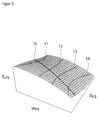
- the w FSi ( b FS ) define on which rolling paths, depending on the position in the width line direction, at which points on the worm the target modification during dressing is to be reached exactly (see FIG. 2 ).
- a function can thus be defined whose zeros, for given b FS 0, provide the adjusting corrections ⁇ K and the axial position ⁇ zS to be set.
- the touch line has to intersect the 4 lines w FSi ( b FS ), resulting in the positions at which the target modification ⁇ nFS ( w FS , b FS ) is to be evaluated.
- the 4-point method has the disadvantage that it does not allow control over the placement of the screw-in modification introduced into the dresser.
- 3-point method only 3 modifications ⁇ FSi are considered at 3 initially restored rolling angles w FSi .
- the radius r FA on the dresser is to produce the radius r FS on the worm.
- the zeros of F F 3 can be calculated, which correspond to the corrections ⁇ K , which have to be set in order to obtain the desired modifications ( ⁇ FS 1 , ⁇ FS 2 , ⁇ FS 3 ) and to map the desired radius on the dresser to the desired radius on the worm.
- This method can also be extended to include the option of specifying a point (w FS 0 , b FS 0 ) to be on the current touch line.
- the function F F 3 must be extended analogously to equation (14) to the function F F 3 .
- ⁇ FS 2 / cos ⁇ bFV is referred to here as c ⁇ FS
- this choice of the modifications F FSi and the rolling angle w FSi leads to a profile crowning between the rolling modes w FS 1 and w FS 3 with the value ⁇ FS 2 / cos ⁇ bFv
- This special case was chosen here because the profile crowning essentially determines whether the desired modification can be achieved with a given worm and dresser geometry.
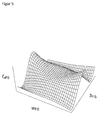
- the course of the axis corrections have over the entire range of achievable on the toothing profile crowning complex forms, which can not be described by simple functions (see FIG. 6 ). In particular, it is not possible to conclude reliably from the progressions in the case of small profile crowns in the entire course. It is thus always advisable to carry out the calculation for the desired profile crowning.
- the axis corrections ⁇ K and the axial position of the worm show steep ascents. On the left edge, this steep rise is particularly evident at ⁇ d, ⁇ ⁇ s and ⁇ ⁇ yA . These edges mark the maximum and minimum producible profile crowning. Beyond the left and right edges, the function F F 3 no longer has zeros.
- the gradients are strongly influenced by the geometric parameters of the screw and the dresser used. So shows FIG. 8 in that, as the diameter of the screw d s increases , the corrections ⁇ K and the axial position ⁇ zS become larger, in particular ⁇ s , ⁇ d and ⁇ ⁇ become significantly greater.
- FIG. 9 shows that with decreasing number of flights of the screw z s , the corrections ⁇ K and the axial position ⁇ zS larger, in particular ⁇ s , ⁇ d and ⁇ ⁇ are significantly larger.
- FIG. 10 shows that with increasing diameter of the dresser d A , the corrections ⁇ K become larger.
- the four figures show the influence of the number of flights of the screw z s , the diameter of the screw d s , the diameter of the dresser d A and the profile angle of the screw ⁇ nF ⁇ on the dependence of the relative profile extension P FS of the profile crowning on the toothing c ⁇ FV
- the relative profile stretch effect affects the active area available on the dresser.
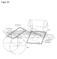
- FIGS. 14a . 14b and 15 show in 3D views from different perspectives and distances the relative position for an uncorrected dressing kinematics, using the example of an involute screw.
- a one-flank dressing is possible without any problems.
- the root 23 of the flight is dressed as desired by the outer surface 20 of the dresser. However, the situation is different when dressing with the 3-point method.
- the FIGS. 16a shows in 3D views from different perspectives and distances the relative position for an uncorrected dressing kinematics, using the example of an involute screw.
- the root 23 of the flight is dressed as desired by the outer surface 20 of the dresser.
- the situation is different when dressing with the 3-point method.
- the FIGS. 16a shows in 3D views from different perspectives and distances the relative position for an uncorrected dressing kinematics, using the example of an involute screw.
- 16b and 17 show for the same screw and the same dresser in 3D views from different perspectives and distances the relative position for a dressing kinematics according to the 3-point method. It shows that the right flank 21 'of the dresser and the outer circumferential surface 20' penetrate the right flank 25 'of the one screw flight. If there is such a penetration, the method can not be used because it leads to an unwanted removal on the right flank 25 '. To avoid this, the dresser can be made narrower. As a result, the outer lateral surface 20 'narrows and the right flank 21' moves closer to the left flank 22 '. The narrowing can theoretically be carried out until the outer lateral surface 20 'has width 0. In practice, however, a minimum width can not be undershot due to production.
- nFs ⁇ (w FS; ⁇ K) are determined for the right flank 25 'with the left flank 24' calculated in accordance with the 3-point method corrections ⁇ K. If the profile modification thus calculated on the right flank 25 'on at least one rolling path w FS below the current oversize, then there is a generally unwanted penetration. In particular, if the calculated profile modification is below the target modification, such a penetration is to be avoided. Another problematic effect results from the change of the center distance ⁇ d by the 3-point method. This often negative change leads, as in FIG. 17 to see the outer jacket surface 20 'penetrate into the screw below the base 23'.
- the 3-point method can be extended to the effect that the modification over the worm width is not the same.
- the procedure is analogous and the equations (15), (16) and (17) then apply to 3 points.
- the assignment of the radii on the dresser to the radii on the screw across the width of the screw can be made variable.
- the fourth component of F F 3 in equation (18) is through r FA r FS b FS ; .DELTA.K - r FA b FS to be replaced.
- r FA ( b FS ) and r FS ( b FS ) describe the assignment of radii on the dresser to radii on the worm, depending on the worm width position.
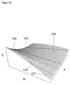
- FIG. 3 shows the modification of a screw which has been dressed with variable allocation of the radii.
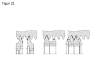
- a dresser for example for involute screws, can not only be used to trim the flanks of a screw, but also to trim the head of the screw at the same time.
- the dressing time can be shortened, because the additional dressing is omitted on a tile, but it is also possible to give the worm head a certain shape to edit the Wälzschleifen the foot of the teeth with.
- Such dressing of the head may be performed on the same flight and at approximately the same width position, but it may be performed on another gear at a different width position (see FIG. 21 ).
- a dresser designed to simultaneously dress the head and flank is usually designed to level the head of the screw at the correct height for a particular dressing kinematics.
- the number of rolling angles at which the modifications are to be achieved must be reduced so that the sum of the number of rolling angles and additional conditions always equals 4.
- the number of rolling angles is at least 2.
- a profile modification placed in the dresser can be additively superimposed.
- the method described in this invention can be applied to double-sided dressing.
- the 3 or 4 rolling angles can be distributed arbitrarily on the two flanks from the 3- or 4-point method.
- the assignment of the radii on the dresser to radii on the check in the 3-point method can be realized on one of the two flanks.
- the modifications that can be produced in double-sided dressing are limited compared to the single-edge production due to the reduced number of considered points per flank, but the double-sided dressing allows shorter dressing times.
- the 4-point variant can be used, for example, to specify allowance and profile angle on both flanks within certain limits.
- the 3-point variant allows only the default 3 of these 4 values, the fourth results automatically, but can be influenced by the geometry of the screw.
- the double-sided dressing can be used both for the production of pure profile modifications as well as topological modifications on the screw.
- the application of this invention does not always have to be over the entire screw width. Thus, only parts of the screw can be dressed with the method underlying the invention. It is also possible to apply several identical or differently modified areas on the screw. Such areas can be used for roughing and / or finishing. It is often the case that two adjacent modified areas can not be placed directly next to each other. This by it The resulting distance between modified areas can optionally be used as a roughing area. This makes it possible to almost completely use a worm subdivided into several partially modified areas.
- the different points considered can optionally be weighted differently, or different distance functions can be used.
- Such a different choice of the distance function or the weighting can be advantageous if the tolerances of the considered points are not all the same. For example, more narrowly tolerated points can be weighted more heavily.
- a typical variant of the compensation calculation, which weights all points equally, is the method of least squares, which uses the 2-norm as a distance function.
- the condition for the assignment of radii on the dresser to radii on the screw can still be maintained in a compensation calculation, so that one obtains an optimization problem with a secondary condition.
- conical screws are meant snails with different pitch heights on the left and right flank. Such a conical screw is in FIG. 36b shown. In the case of involute snails these are called Beveloids.
- radii on the dresser it is of particular importance to assign radii on the dresser to radii on the worm variable over the worm width, since due to the conicity, at each width line position the worm is trued over a different diameter range.
- the points on the worm that grind the beginning of a tip retraction of the gearing are at a different radius at each width position.
- dressers designed for a particular screw diameter can be used for a wide range of screw diameters and produce the desired profile modification on the screw during dressing, which then produces the correct profile modification on the gear.
- this no longer works if the ratio of screw diameter to modulus of the toothing to be ground, too small and / or the number of turns is large. Screws with small diameters are used, for example, when generating grinding with a larger screw is no longer possible due to a disturbing contour. Another application is the grinding of large-modulus gears. Since the usable screw diameters are limited to the top, the ratio of screw diameter to the module decreases with increasing module. With the possibility of modern high-speed machines to realize high table speeds, it is also possible to use screws with larger numbers.
- a dresser designed for the screw in new condition produces an undesirable profile error for smaller radii, in the case of involute screws an undesirable profile crowning, when dressed according to a method according to the prior art. If this profile error or this profile crowning below a screw diameter outside the tolerance, so the screw can not be trained with the given dresser, causing the maximum usable pad thickness is limited. So far this problem can only be solved by using different dressers for different diameter ranges. With the method described here, however, it is possible to keep constant the profile shape over a large diameter range with only one dresser. For this purpose, the dresser is regarded as a dresser which does not fit the screw and the dressing kinematics are determined in such a way that the desired profile shape is produced on the screw.
- the 3-point method is preferably used so that a radius on the dresser can be assigned to a radius on the worm.
- this method results in a generally undesirable relative tread extension on the toothing (see FIG. 19a ).
- Such a relative extension of the profile is not critical if the profile modification introduced in the dresser has to be assigned exactly to a maximum diameter on the toothing. This is the case, for example, if only a return on the profile to be introduced. However, if the profile modification has at least two such diameters, for example a head and a foot return, then these two points would move closer and closer due to the relative profile extension with decreasing screw diameter.
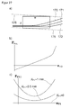
- FIG. 19c shows the profile angle determined in this way for different worm radii.
- the combination of the 3-point method with the choice of suitable profile angles makes it possible, with small screw diameters and / or large numbers of gears, to keep the profile shape on the toothing virtually constant over a very large range of the screw diameter.
- the profile error or profile crowning can be corrected analogously. If the relative profile extension is also to be corrected for involute screws, then a correction via the profile angle of the screw during grinding with cylindrical screws is only possible to a limited extent.
- the calculation of the profile angle, which makes the relative tread extension disappear, must be carried out separately on the left and right flank and generally leads to a worm, which no longer is suitable for Wälzschleifen the gearing, since equation (20) is no longer satisfied for both sides.
- it can be used a cylindrical screw whose profile angles are selected on the right and left flank so that the teeth can be ground and the relative profile extension is minimized on the left and right flank.
- the use of a conical (beveloid) screw is possible. The cone angle of this screw can then be selected so that the teeth can be ground with the screw and the relative profile extension is 0 on both flanks.
- dressers which have contact between the screw head and the screw root during dressing.
- the invention makes it possible to influence the profile shape with such dresser, so there are profile modifications that are not possible with a universal dresser. In wage and small batch production, however, high flexibility is required. If dressers with smaller active areas are therefore used, only parts of the profile can be dressed with them per stroke, and in each of these areas the method described here can be used; in particular, the modification can be specified on 3 or 4 pitch paths. This allows a very flexible design of the profile modification, but requires significantly fewer strokes compared to a known from the prior art line leveling with point contact.
- the 3-point method can be used here to assign the active area of the dresser to the area to be dressed in the current stroke in each stroke.
- FIG. 20a shows by way of example a profile modification ⁇ nFS , which is composed of the 3 areas 30, 31, 32. In each of these areas, profile angle deviation and profile crowning can be specified separately.
- the areas 30 and 32 are dressed in one stroke, the main profile 31 in 4 strokes.
- the size of the active area on the dresser is chosen here so that the area 34 begins below the scholarnutz Vietnamesees w NfFS of the check . Such a fall below the convennutznikes is not critical within certain limits, since this area of the screw generally has no contact with the toothing during hobbing.
- a suitably large choice of dresser has the advantage that less strokes are needed for the main profile, compared to an active area, with the Schwarznutz Vietnamese not fell below.
- Such a dresser and a method which describes such a mapping are already from the DE19624842C2 known.
- the dressing in several strokes can not only be used to produce pure profile modifications, but can be transferred directly to the dressing of topologically corrected screws, analogous to dressing in a hub. It is possible to move the areas that are trained during a stroke across the width of the screw. For example, the positions of the transitions between the areas 30 and 31 or 31 and 32 in FIG FIG. 20a be freely specified over the screw width. Such a modified screw can then be used, for example, to realize by means of diagonal roller grinding on the toothing over the tooth width variable start of the head and foot returns.
- a dresser used with several strokes may also already contain modifications that are then placed specifically on the screw.
- a dresser may have an area that is used to create the head return, part of the main profile and the bend between the two, and a second area that is used to create the foot return, part of the main profile, and the bend between the two. If then the upper part of the profile in a stroke with the first area and the lower part trained with the second area, the courses of the beginning of the head orlessness Wegdging across the width of the screw can be specified independently and at the transition between the upper and lower part of the profile, a tangential transition can be realized.
- Such a dressed screw can be used in the diagonal rolling process to freely specify the beginning of head and foot return on the toothing depending on the width position.
- multi-stroke dressing it is also possible in principle to use more than just one dresser, thus allowing individual strokes to be carried out with different dressers. These can have different modifications and / or geometries and thus allow an even more flexible dressing.
- Part of this invention is also a calculation unit / software which, for a given modified toothing for a given set of geometrical sizes, checks the manufacturability with the method according to the invention, preferably taking into account the modification introduced into the dresser. If, for example, a profile crowning of 20 ⁇ m is to be produced in the case of involute toothing, but only one dresser with a modification for producing 15 ⁇ m is available, it must be checked whether, for example, with the 3-point method, a profile crowning of 5 ⁇ m can be generated.
- Such a calculation unit / software may additionally include a function for a set of geometric quantities including dressing modification to a toothing to calculate all modifications that can be generated with the invention.
- the maximum and minimum producible profile crowning can be determined. If the dresser contains a modification which is to be imaged as a profile modification on the toothing and this modification is to be superimposed by a modification produced according to the invention, it is optionally additionally to check whether the modification is still due to the resulting relative extension of the profile Tolerance is correctly mapped on the gearing.
- a computing unit / software may also include functionality to compute modified gearing and an incomplete set of geometric sizes including dresser modification, default values for the remaining geometric sizes. If, for example, the dresser together with the modification and the number of flights of the screw are provided, the diameter of the screw and / or the profile angle of the screw can be determined such that the required modification can be produced by the method according to the invention. If such a calculation unit / software has a database with available dressers and / or screw diameters, the software can determine all combinations suitable for generating a specific modification. Such a database may additionally or instead of the screw diameter also contain data on already pre-profiled available screws. Such data would include, for example, number of flights and / or diameter and / or taper and / or profile angle and / or pitch. Such functionality is of particular interest to pay-dividers, since in this way screws and dresser can be used for different gears.
- Such calculations can be made not only for pure profile modifications, but also for topological modifications on the screw.
- the calculation is carried out, for example, for discrete width positions.
- Such a calculation provides, for example, possible function values for the functions C 0 FS ( X FS ), C 1 FS ( X FS ) and C 2 FS ( X FS ) from equation (23), and thus describes the amount of topological modifications that can be generated, in particular the minimum and maximum producible profile crowning along the Berntonline. If these minimal and maximum required profile crowns are known for a topological modification, then again suitable geometric variables can be determined. Especially for such topological modifications, such functionality is of great importance not only in contract and small batch production, but also in process design for mass production. When reversing the calculation to determine suitable geometric sizes and dressers, the most critical width position is preferably taken into account.
- FIGS. 8 . 9 . 10 and 11 show the sometimes very strong influence four of the geometric variables on the axis corrections.
- over-corrections can be detrimental. If axes are moved too far, for example, collisions between the worm and / or dresser with machine parts can occur. Another problem is the increasing by the large travels deviations in the positioning of the dresser relative to the screw.
- the amounts of the axis corrections are orders of magnitude greater than the amounts of the profile modifications to be generated, and in these cases significantly above the axis corrections which are typically required in the prior art methods.
- the influence of such variations on the generated modification, with the function ⁇ (NFS WFs; ⁇ K) are calculated, wherein ⁇ K is provided with a deviation. If the deviations of the axes, which are primarily mechanical, are known, depending on the axis corrections, then the influence on the profile modification to be generated and the error in the profile modification can be calculated.
- the geometric sizes can then be determined so that the error in the profile modification is below a given tolerance. This consideration can be transferred directly to the generation of topological modifications, in which case the calculation for different positions of the contact line is preferably to be carried out.
- the unfavorable axis values with large deviations can preferably be set if the contact line passes over areas of great tolerance.
- the deviations of the axes are not known, they can be recalculated from the error caused by them in the profile.
- the calculation on which the invention is based is used in order to calculate the axis corrections ⁇ K from the profile modification actually produced. These are compared with the axis corrections set in the machine during dressing and the difference results in the deviation of the axis values. If a topological modification is dressed, this calculation can be performed for different positions of the touchline. In this way one obtains the deviations for different axis values. If the deviations are known, the axis values can be corrected accordingly for further dressing processes and thus the profile errors minimized.
- the effect of the profile extension can also be used selectively. For example, if a worm is to be dressed with a modified dresser, but the modification introduced into the dresser would produce a stretched or upset profile modification on the worm, then the method of the invention can be used to set the relative tread extension such that the screw produced on the worm Profile modification is properly stretched. If a relative profile extension is produced, for example, involute profiles result in a profile crowning at the same time. How big this is for a given relative stretch depends mainly on the geometrical sizes of the screw and the dresser (see FIG. 13 ). In certain cases, this profile crowning can be so small that substantially only one stretching results, but no superimposition with a profile crowning. To achieve this, the screw geometry can be selected accordingly.
- the screw geometry so that not only the profile extension, but also the profile modification produced by the dressing kinematics, in particular the profile crowning in the case of involute toothing, is achieved according to a specification.
- This can also be transferred to the dressing of topologically modified screws, which makes it possible, with a suitable worm and dressing geometry, specifically to vary the profile extension over the worm width and at the same time only to produce a negligibly small profile crowning.
- the linear coupling in the first approximation is in FIG. 13 shown.
- the profile extension and, for example, the profile modification have an effect on each width position along the current contact line.
- a conical screw can be used and in addition a variation of the cone angle for the separate adjustment of the left and right flank coupling can be used. With decreasing screw diameter changes However, this coupling, which can be corrected by a correspondingly adjusted adjustment of the profile angle again.
- both dressable and non-dressable tools can be used.
- the dressing can be done with a profile roll one or two lines, but also one or two lines in line dressing.
- the machining process is performed using a tool length modified tool, which is moved in the axial direction during the process (diagonal rolling).
- topological surface modifications which can be generated by the method first described here.
- X F w F sin ⁇ F + z F cos ⁇ F .
- ⁇ Ft ( w F , z F ) describes the surface modification exactly or at least approximately.
- Each X F uniquely defines a straight line on the flank in the coordinates w F and z F.
- the definition of the surface modification means that along each straight line given by an X F , it has the shape of a parabola (polynomial of the second degree) or can be approximated by it.
- the shape of the parabola, and thus the coefficients of the polynomial, may be different for each such line.
- the surface modification along the line defined by X F is given by a linear function, where again the function may degenerate to a constant function for some X F.
- the surface modification is a pure flank line modification, ie the surface modification is constant over the entire profile in any given incision cut.
- ⁇ F ⁇ ⁇ 2 .
- the surface modification is a pure profile line modification.
- This parameterization makes it possible to calculate simple relationships for the course of the contact point on tool and workpiece. This course is continuously shifted both on the workpiece and on the tool by the axial feed of the workpiece and the shift movement of the tool.
- the knowledge of these gradients makes it possible to uniquely assign a point on the workpiece to a point on the tool and vice versa. With this assignment, the ratio between axial feed of the workpiece and shift movement of the tool, referred to below as the diagonal ratio, and the surface modification on the tool can be adjusted so that the desired modification is produced on the workpiece.
- coordinates are used here for generalized, not necessarily independent coordinates.
- the axis of rotation of a toothing always coincides with the z- axis in its rest system.
- the calculation of the coordinates A 1 , ..., A N s can be performed by means of a coordinate transformation.
- H R z ⁇ B 1 ⁇ T z - ⁇ V 1 ⁇ R x 90 ° - ⁇ A 1 ⁇ T z - ⁇ Z 1 ⁇ T x - ⁇ X 1 ⁇ R z ⁇ C 2
- Example 2 R z ⁇ B 1 ⁇ R x 90 ° - ⁇ A 1 ⁇ T z - v Y 1 ⁇ T z - v Z 1 ⁇ T x - v X 1 ⁇ R z ⁇ C 2
- FIG. 22 schematically showing a gear cutting by a method described by H Ex 1 musculoskeletal system.
- the z V 2 coordinate is traversed, thus realizing the feed of the workpiece.
- this is the axial feed
- this feed is not axial, but tilted by the cone angle ⁇ 2 with respect to the axis of the toothing.
- the z V 1 coordinate is additionally moved, which realizes the feed of the tool.
- this is the Axiavorschub, with conical wheels, this feed is not axial, but tilted by the cone angle ⁇ 1 relative to the axis of the tool.
- feed is also used for cylindrical tools or workpieces for z V 1 or z V 2 .
- K Z V 1 Here is the diagonal ratio and z V 01 a fixed offset, which makes it possible to place the modifications described here at different locations on the tool or to select the area on the screw to be used. Is K Z V 1 ⁇ 0 is spoken by the diagonal rolling process.
- the four possible combinations of cylindrical or conical tools and workpieces are considered separately.
- the starting point is in each case the mathematical description of the course of the contact point on the tool and workpiece during generating grinding as a relation between the rolling path ( w ) and the position in the width direction (z) as a function of the feed positions z V 1 and z V 2 .
- the tools, cylindrical and conical screws, symmetrical or asymmetric, which are considered here, also have at least approximately a modification according to equation (25).
- This type of modification is very advantageous, in particular for dressable grinding worms, since it can be produced on the worm during dressing with a dressing wheel.
- a method of dressing a screw having such a surface modification is described in the first part of this application.
- a modification ⁇ nF 1 at a point on the worm, defined in the normal direction on the worm gear surface, leads to a modification ⁇ nF 2 - ⁇ nF 1 on the workpiece, defined in the normal direction on the tooth flank surface, at the corresponding point on the workpiece.
- C Fw 1 , C Fc 1 , C Fw 2 and C Fc 2 introduced here have the following dependencies:
- C fw 1 C fw 1 ⁇ bF 1
- C F ⁇ 1 C Fc 1 ⁇ bF 1 ⁇ bF 2 r bF 1 d ⁇
- C fw 2 C fw 2 ⁇ bF 2
- C Fc 2 C Fc 2 ⁇ bF 1 ⁇ bF 2 r bF 2 d ⁇
- Equation (39) and (40) are resolved to z V 1 and z V 2 and used in equation (36), then equation (7) used for screw and workpiece to z F 1 and z F 2 to eliminate and with equation (45) w F 1 replaced.
- C ⁇ Fc + C ⁇ fw 2 ⁇ w F 2 0 . which must apply to all w F 2 .
- Fw 2 has a dependence on K z V 1
- FC has a dependence on X F 1 and X F 2 .
- K z V 1 calculate both left and right flank, and X F 2 as a function of X F 1 , also for left and right flank.
- K Z V 1 As defined in equation (36), the diagonal ratio with which the machining process must be performed determines the mapping of the points on the Snail on the points on the workpiece along the direction defined by ⁇ F 2 direction.
- a one-flank deviation-free generating grinding is possible, however, for the processing of the left and right flanks different diagonal K Z V 1 are to be adjusted. Is there a diagonal ratio K Z V 1 so that the generated modification on the left and right flank is still within the respective tolerance during generating grinding with this, a two-sided, but no longer deviating free generating grinding is still possible.
- the diagonal ratio to be chosen for this is usually between the diagonal ratios determined for the left and right flanks.
- the direction ⁇ F 2 of the modification produced on the workpiece deviates from the target specification on at least one of the two edges. However, if this target specification is tolerated, then it is possible in certain cases to choose the diagonal ratio such that both directions ⁇ F 2 are within the tolerance.
- C Fw 1 , C Fc 1 , C Fw 2 , C Fz V 1 1 , C Fz V 1 2 and C Fc 2 have the following dependencies:
- C fw 1 C fw 1 ⁇ bF 1
- C Fc 1 C Fc 1 ⁇ bF 1 ⁇ bF 2 r bF 1 d ⁇ ⁇ 1
- C fw 2 C fw 2 ⁇ bF 2
- C Fc 2 C Fc 2 ⁇ bF 1 ⁇ bF 2 r bF 2 d ⁇ ⁇ 1
- C Fz V 1 1 C Fz V 1 1 ⁇ bF 1 ⁇ bF 2 r bF 1 d ⁇ ⁇ 1
- C Fz V 1 2 C Fz V 1 2 ⁇ bF 1 ⁇ bF 2 r bF 2 d ⁇ ⁇ 1
- C Fz V 1 2 C Fz V 1 2 ⁇ bF 1 ⁇ bF 2
- a change in ⁇ 1 generally requires a change in the base circle radii and the base taper angle of the worm, so that the worm and the workpiece can continue to mesh with one another, thus forming a helical gear.
- the profile angles of the rack generating the worm and the axis cross angle ⁇ also influence the value K Z for conical worms V 1 ,
- these quantities can be varied to the same K Z V 1 to get left and right flank.
- This change in the profile angle also leads to a change in the base circle radii and the base angle of the worm.
- C Fw 1 , C Fc 1 , C Fw 2 , C Fz V 2 2 , C Fz V 2 1 and C Fc 2 have the following dependencies:
- C fw 1 C fw 1 ⁇ bF 1
- C Fc 1 C Fc 1 ⁇ bF 1 ⁇ bF 2 r bF 1 d ⁇ ⁇ 2
- C fw 2 C fw 2 ⁇ bF 2
- C Fc 2 C Fc 2 ⁇ bF 1 ⁇ bF 2 r bF 2 d ⁇ ⁇ 2
- C Fz V 2 2 C Fz V 2 2 ⁇ bF 1 ⁇ bF 2 r bF 2 d ⁇ ⁇ 2
- C Fz V 2 1 C Fz V 2 1 ⁇ bF 1 . ⁇ bF 2 . r bF 1 . d . ⁇ . ⁇ 2
- C Fw 1 , C Fc 1 , C Fw 2 , C Fz V 2 2 , C Fz V 2 1 , C Fz V 1 2 , C Fz V 1 1 and C Fc 2 have the following dependencies:
- C fw 1 C fw 1 ⁇ bF 1
- C Fc 1 C Fc 1 ⁇ bF 1 . ⁇ bF 2 . r bF 1 . d . ⁇ . ⁇ 1 .
- FIG. 37 shows by way of example the touch of a right involute flank with a generating rack with profile angle ⁇ twr in the end section.
- the toothing is rotated by the rotation angle ⁇ .
- the contact between flank and rack takes place in the engagement plane P r , which is inclined by ⁇ twr .
- the contact point between the flank and the rack results for all angles of rotation ⁇ as the point of intersection between flank and engagement plane.
- the toothed rack is moved horizontally, so that it unrolls without slip on the pitch circle with radius r w .
- flank and rack remain in contact.
- the relative position of the rack to the teeth in 3D must be considered.
- the end cuts can be determined for any width positions and in them the point of contact between toothed rack and flank. All these points of contact in the individual end sections form a straight line (contact straight line) in the engagement plane for a rotation angle ⁇ . If one describes these points of contact via w and z from the parameterization in equation (27), one obtains a linear relationship (R1) between w, z and ⁇ . If the rack is held in space, it is possible for cylindrical gears to move them in the axial direction. This axial feed z V is typically set for the workpiece to process over the entire toothed width and set for the tool to set the diagonal ratio.
- two-sided contact with the toothed rack means that the toothing must be turned around its axis in addition to the displacement.
- the amount of rotation results from the pitch of the teeth and the amount of displacement, the sense of rotation from the pitch direction.
- the advance z V does not take place in the axial direction but is tilted relative to the latter by the cone angle ⁇ .
- the height required for the calculation of the angle of rotation correction is calculated according to the same formula as for cylindrical gears from ⁇ w and m t .
- the end sections depending on the axial feed or feed with the correspondingly corrected rotation angles are to be considered.
- (R1) results in a linear relationship (R2) between w, z, z V and ⁇ .
- the point of contact of the two teeth can be determined directly by calculating the point of intersection of the two contact straight lines.
- the parameters z F 1 and w F 1 or z F 2 and w F 2 which describe the contact point on toothing 1 or toothing 2, depend linearly on ⁇ 1 , ⁇ 2 , z V 1 and z V 2 (R5 ). If the angles of rotation are eliminated in these relations, the sought-after contact paths (R6) follow.
- a, usually not modified workpiece is considered first.
- vectors are placed in the normal direction with a predetermined length.
- the length of the vectors corresponds to the allowance of the workpiece before grinding, relative to the unmodified workpiece.
- the allowance is typically chosen so large that each vector is truncated at least once during the simulation described below.
- the number of points on the teeth determines the accuracy of the result. Preferably, these points are chosen equidistantly.
- the relative position of the workpiece to the screw is given at any time, for example by the kinematic chains K r . At each of the discrete times, the intersection of all vectors with the screw is calculated.
- a vector does not cut the screw, it will remain unchanged. However, if it cuts the screw, the intersection is calculated and the vector is shortened so far that it ends just at the intersection. Furthermore, the distance of the point of intersection from the screw axis, that is, the radius on the screw r F 1 of the point of intersection is calculated and stored as additional information to the just shortened vector.
- the corrections of the coordinates are not changed during grinding, after the simulation has been performed on the whole width of the screw, all the vectors on a given radius of the workpiece r F 2 and a given pitch w F 2 have approximately the same length.
- the small differences in the lengths are due to the fact that the algorithm described here causes markings, similar to the envelope cuts during hobbing, due to the discretization of the time. These markings and thus also the differences in the lengths of the vectors on a given radius of the workpiece can be reduced by a finer discretization of time, equivalent to a shortening of the time steps. If the simulation is not performed over the entire width of the workpiece, but aborted at a given axial shift position z V 2 of the workpiece, then for a given radius on the screw only the vectors approximately the same length already swept by the contact path.
- the remaining vectors either still have the originally chosen length or have already been truncated at least once, but do not yet have the final length, as they will be truncated at a later date (see Figure 38 ).
- This fact can be used to determine the contact path for the actual feed rates of the workpiece and the worm very accurately.
- all vectors are considered for a given radius on the workpiece r F 2 or Wälzweg w V and determines at which latitudinal line position, the transition from vectors of approximately equal length to those with a different length. Since the lingermélzgetriebe is symmetrical against swapping of workpiece and screw, can be determined in the same way, the contact path on the screw.
- the coefficients from equation (39) or (40) can be determined from the points calculated in this way on the contact path, for example by means of a compensation calculation. If the vectors along which the contact path runs are determined, the radii previously stored thereon can be read out on the worm r F 1 and thus determined for each radius on the workpiece r F 2 , of which radius on the worm r F 1 of this was ground. These radii can be converted into Wälzwege. From these pairs of values, the coefficients from equation (45) can be determined for cylindrical workpieces and cylindrical screws, for example by means of a compensation calculation.
- the contact path must be determined for at least two different feeds z V 1 to additionally determine the coefficients before z V 1 in equations (50), (51) and (58).
- at least two different feed rates z V 2 must be considered if the workpiece is conical and the screw is cylindrical. If the workpiece and worm are conical, then the contact paths must be considered for at least two feeds z V 1 and at least two feeds z V 2 in order to determine all coefficients from equations (76), (77) and (86).
- the diagonal ratio calculated here depends on the macro geometry of the worm, in particular the number of turns, the base bevel angle, the base circle radii, the outside diameter (in the case of a conical tool at a defined z position) and possibly the cone angle. These quantities can therefore be used to set the diagonal ratio to be set for given directions ⁇ F influence. This also makes it possible to extend or shorten the work area, which can be advantageous for the tool layout. Also, influencing the diagonal ratio for technological reasons may be useful.
- the macrogeometry should be selected so that the required surface modification on the screw can be generated by the dressing process. In this case, it must be ensured in particular that the required crowning can be achieved along each contact straight line on the screw with the dresser contacting the active region of the screw. If a two-sided dressing is used, it should be considered whether the required topological modifications on the left and right flank screw can be generated, for example, by the method of the first part of this application. Particularly relevant is the case in which only constant and linear portions of the modification ( F FtC and F FtL ) along the contact line between dresser and screw are needed.
- the method described so far requires that the machining process be carried out with a constant predetermined diagonal ratio.
- the diagonal ratio and the width of the workpiece including overflow determine the feed of the workpiece required for machining.
- the feed determines the length of the part of the tool involved in the machining, also referred to as the work area.
- the length of the working area determines, on the one hand, the minimum length of the tool or, in the case of short work areas and long tools, the number of modified areas that can be placed on the worm. In either case, it may be beneficial to extend or shorten the length of the work area.
- One way to change the length of the workspace is to change the geometry of the tool, especially the base circle radii and base skew angle.
- the modification is such that the course of the contact point sweeps over areas that are not modified, the parts of the worm which are currently in engagement are also not modified.
- This allows, while sweeping this area, to freely choose the diagonal ratio.
- the diagonal ratio can be set to 0. A reduction of the diagonal ratio, however, leads to a greater stress on the tool, which makes a technological analysis necessary. If the removal is particularly large while the unmodified area is being manufactured, then it may also be useful to increase the diagonal ratio in these areas.
- Typical examples of modifications which consist of an unmodified region are end reductions or triangular end reductions.
- FIG. 23 shows a division into modified (141 and 141 ') and unmodified (142, 142', 142 ") regions using the example of two triangular end reductions: While the course of the co-occurrence point (143 or 143 ') passes over the region 142, only the values do not arise In this range, the diagonal ratio can be freely selected: If an area above 143 or below 143 'is swept over, the contact point extends at least partially over a modified area However, it is also possible to disregard the diagonal ratio and to accept deviations If two sides are ground, then both flanks must be taken into account In order to produce a deviation - free modification, the diagonal ratio can only be freely selected during the Contact path on both flanks one not mo overrides the modified area.
- modifications that consist of unmodified areas and areas with mutually-differentiated modifications. If the modification is such that the course of the contact point between the modified areas sweeps over areas which are not modified, then the diagonal ratio can again be selected arbitrarily in these areas. Become modified areas have been swept over, so the diagonal ratio must be adjusted according to the direction of the modification just swept over. The unmodified areas can be used to adjust the diagonal ratio from one modified area to the next.
- FIG. 24 shows in the example of two triangular end return, which run in different directions, a division into modified (151 and 151 ') and unmodified (152, 152', 152 ") areas
- the directions ⁇ F 2 (150 or 150 ') of Modifications according to equation (25) are different for the modified regions, so different diagonal ratios have to be set for the processing of the two regions, while the course of the Kotaktticians (153 or 153 ') covers region 152, the diagonal ratio can be chosen freely
- the straight lines 153 and 153 'must be at the same level or 153 above 153', but if 153 'exceeds 153, the contact point extends both over the region 151 and over the region 151', for which different This results in a deviation on at least one of the two areas grinded, a consideration of both flanks is also necessary here. If you want to ground without deviation, make sure that the areas ground on both sides at the same time require the same
- F Z is V 1 any continuous function that describes a relation between z V 1 and z V 2 .
- the diagonal ratio is due to the derivative of F Z V 1 ( z V 2 ) given to z V 2 and thus generally not constant.
- the curve showing the course of the points in the w - describes z -diagram on the workpiece, are mapped which defined a through X F 1 Straight on the screw, by a function z F 2 (w F 2, X F 1) to be discribed.
- FIG. 25a shows this example of a cylindrical workpiece. This can be used to F Z V 1 ( z V 2 ) piecemeal from the gradients for different X F 1 fauxzupaten, or expand the definition area.
- F Z V1 ( z V 2 ) from a course for an X F 1 , which has continued beyond the limits of the w - z diagram to determine.
- This course is advantageously continued so far that each part of the w - z diagrams is covered by the course.
- FIG. 25a shows how such a course can be chosen.
- the function F Z V 1 ( z V 2) are then determined from one of the four traces 160-163.
- this calculation yields that a trace X F 1 results from passing through for another X F 1 by shifting along an excellent direction.
- this direction is represented by the two parallel lines 165 and 166.
- the direction of this line is independent of the geometry of the screw and thus depends only on the geometry of the workpiece.
- conical screws can be used. About the geometry of conical screw ( r bF 1 or ⁇ bF 1 ) and Achsnchwinkel and center distance, in particular the cone angle, this direction can be influenced.
- the change in the shape from one X F 1 to another, for both conical and cylindrical screws can be influenced by the geometry of the screw ( r bF 1 or ⁇ bF 1 , ⁇ 1 ) and the axis cross angle.
- the relationship can no longer be easily described in this case and must be determined by the steps described above.
- F Z can be used V 1 ( z V 2 ) and thus the course for each edge are specified separately.
- the resulting course on edge 2 is influenced by the geometry of the worm ( r bF 1 or ⁇ bF 1 , ⁇ 1 ) and axis cross angle and center distance. This influence can be used to F Z V 1 ( z V 2 ), the geometry of the worm and Achsnchwinkel and center distance to tune so that the curves on both flanks as well as possible correspond to the desired gradients.
- the value of the modification on the workpiece along a course z F 2 ( w F 2 , X F 1 ) is at least approximately the same: - cos ⁇ bF 1 cos ⁇ bF 2 ⁇ F Ft 1 C X F 1 + F Ft 1 L X F 1 ⁇ w F 1 + F Ft 1 Q X F 1 ⁇ w F 1 2
- the function values of the functions F Ft 1 C , F Ft 1 L and F Ft 1 Q can be determined for all courses.
- the functional values, taking into account the modification to three Rolling angles are determined along the course, in an extended variant, this can be done by means of a compensation calculation.
- the modification is chosen so that it approximates the combination of a triangular end return and an end withdrawal in the flank line direction, the final return, the closer one comes to the end face, is more pronounced at the top and bottom of the toothing, as in the middle of the profile.
- the transition between the beginning of the two redemptions is selected here as an example tangentially, whereby the curve 170 is given by a differentiable curve.
- the value of the modification along 170 is set equal to 0 here.
- the modification along 170 and 171 depending on the pitch angle of the gearing, can be determined by means of equation (95) Figure 27c be read.
- the slope of the modification in the region of the end withdrawal in the flank line direction is greater than in the region of Triangular final return.
- the ratio of these two gradients is significantly influenced by the direction of the displacement of the curves (175 and 176). This direction can be adjusted by the use of conical screws and by choosing a suitable geometry of the screw. Thus, the ratio between the slopes can be adjusted as desired.
- the functions F KFt can be any continuous functions. From the functions F KFt for left and right flank, the necessary corrections of the grinding kinematics can be calculated. For example, naturally entangled crowns or distorted end reductions can be produced with this method.
- f GFt w F z F F FTC X F + F FtL X F ⁇ w F + F FTQ X F ⁇ w F 2 + f PFt w F + m F z F +
- a modification f F can generally be approximated, in some cases also exactly, for example with the aid of a compensation calculation, into the three terms from equation (100).
- the functions F FtC , F FtL , F FtQ , f PFt and F KFt and the directions ⁇ F are determined such that the deviations between f GFT and f F are optimal, in particular minimal.
- This deviation can, for example, at discrete points (Fi w, z Fi) or continuously over the whole w - z -diagram be calculated.
- the continuous calculation of the deviation can be carried out, for example, by means of an integral of a distance function over all values of w and z.
- the desired modification may, for example, be given by a continuous function f F , by a point cloud ( w Fj , z Fj , f Fj ) or a combination of both.
- the functions F FtC , F FtL , F FtQ , f PFt and F KFt can be calculated as continuous functions using the compensation calculation.
- the teeth are often machined in roughing and finishing cuts. These different processing steps can be performed both with the same areas on the tool as well as with different areas or with different tools.
- the roughing cuts may be performed in whole or in part by the method described herein. However, it is also possible to perform for the roughing cuts other methods, in particular the axial grinding with diagonal ratio zero or a very small, technologically related diagonal ratio. Such roughing makes it possible to make better use of the roughing zone (s) on the worm, but does not produce the desired modification on the gearing. If the method described here is already used during roughing, the allowance is distributed more uniformly at the beginning of the finishing process and the sizing area is loaded more uniformly.
- non-dressable tools can also be used as long as they have a modification according to equation (25).
- ⁇ F the direction of constant modification given by ⁇ F or at least within certain limits, which in turn can influence the diagonal ratio during generating grinding and thus also the working range. This free choice of ⁇ F is also possible when line dressing the tool.
- the method can also be used in other manufacturing processes that use a toothed tool and the kinematics of a screw gear and allow a feed of the tool.
- These other manufacturing processes include, for example, hobbing, peeling hobbing, scraping and honing.
- the tools must also have a modification according to equation (25). Depending on the manufacturing process of the tool, a free choice of ⁇ F on the tool is also possible here.
- K F 10 can be freely specified for left and right flank, for example. This is of particular interest when dressing is to be two-sided.
- K F 10 essentially describes how far the dresser has to be swiveled about the C5 axis at a position X F 1 , if for dressing purposes a movement as in FIG. 22 is being used.
- K l 10 and K r 10 can now be chosen so that for two position X l 1 and position X r 1 on the left and right flank of the worm, which are dressed at the same time, the same pivot angle of the C5 axis is set. Whether the tilt angle of the C5 axis is the same over the entire area of the worm to be dressed depends on the coefficients K F 11 and the macro geometries of the tool and the workpiece, in particular whether they are symmetrical or asymmetrical and cylindrical or conical. However, it is also possible within certain limits to make a screw double-sided, if different C5 angles are required. For this purpose, all degrees of freedom in dressing can be used, as described in the first part of this application. For this purpose, for example, two of the exactly to be reached 4 points can be selected on the left and right flank. Thus, a method is available for producing a very wide range of the modifications defined by Equation (101), employing single or double-sided dressing.
- Such a two-sided dressing can be further optimized by the fact that the diagonal ratio is determined so that the required topological modification on the screw can be generated as easily as possible.
- the diagonal ratio should be selected so that K l 11 and K r accept 11 corresponding values.
- the diagonal ratio and thus the range of the pencil and the size of the area used on the screw can be freely selected within certain limits.
- the number of area on a screw for example, be optimized considering technological aspects or optimally adapted to the screw length.
- FIG. 29 Another effect resulting from the free choice of diagonal ratio is the possibility of superposition with modifications requiring a fixed diagonal ratio.
- FIG. 29 shows the additive superimposition of a triangular end return, a profile crowning and a tangle-free flank liner crowning, wherein the profile crowning is produced by the method described here and not via a suitably designed dresser.
- the diagonal ratio must be chosen so that the return falls in the correct direction. This direction is defined by the line 123, which is a straight line in w and z.
- the proportion of modification that comes purely from the triangular final return is constant.
- FIG. 32 shows an upper and a lower surface, which envelop the waviness. The upper surface defines the amplitude function of the ripple as a function of w and z.
- an amplitude function was selected by way of example, which has a smaller value in the middle of the edge compared to the edge of the edge and is given as the sum of two polynomial second degree in w or z. Amplitude functions are also possible which lead to smaller amplitudes at the edge of the edge.
- the ripple with non-constant amplitude is obtained by multiplying the amplitude function by the ripple sin X F 2 ⁇ + ⁇ , The resulting modification thus has a form according to equation (25) and is in FIG. 33 shown.
- Such ripples can, as well as in DE102012015846 can be used to optimize the excitation behavior of gears, but allow due to the different amplitude on the tooth flank additionally optimized for different load levels.
- flanks of the flights are trued in several strokes, it is possible to dissect different portions of the flanks in each stroke, e.g. at the first stroke an upper part of the profile, at the second a lower part, and thereby apply different modifications in the different areas.
Landscapes
- Engineering & Computer Science (AREA)
- Mechanical Engineering (AREA)
- Physics & Mathematics (AREA)
- Human Computer Interaction (AREA)
- Manufacturing & Machinery (AREA)
- General Physics & Mathematics (AREA)
- Automation & Control Theory (AREA)
- Geometry (AREA)
- Grinding-Machine Dressing And Accessory Apparatuses (AREA)
- Gear Processing (AREA)
- Grinding And Polishing Of Tertiary Curved Surfaces And Surfaces With Complex Shapes (AREA)
Applications Claiming Priority (1)
| Application Number | Priority Date | Filing Date | Title |
|---|---|---|---|
| DE102015009017.8A DE102015009017A1 (de) | 2015-07-10 | 2015-07-10 | Verfahren zur Herstellung eines verzahnten Werkstückes mit modifizierter Oberflächengeometrie |
Publications (3)
| Publication Number | Publication Date |
|---|---|
| EP3139231A2 true EP3139231A2 (fr) | 2017-03-08 |
| EP3139231A3 EP3139231A3 (fr) | 2017-08-16 |
| EP3139231B1 EP3139231B1 (fr) | 2021-08-18 |
Family
ID=55970922
Family Applications (1)
| Application Number | Title | Priority Date | Filing Date |
|---|---|---|---|
| EP16169746.1A Active EP3139231B1 (fr) | 2015-07-10 | 2016-05-14 | Procede de fabrication d'une piece dentee comprenant une geometrie de surface modifiee |
Country Status (5)
| Country | Link |
|---|---|
| US (1) | US10500659B2 (fr) |
| EP (1) | EP3139231B1 (fr) |
| JP (1) | JP6780970B2 (fr) |
| KR (1) | KR102616618B1 (fr) |
| DE (1) | DE102015009017A1 (fr) |
Cited By (1)
| Publication number | Priority date | Publication date | Assignee | Title |
|---|---|---|---|---|
| EP4095631A1 (fr) * | 2021-05-25 | 2022-11-30 | Klingelnberg GmbH | Procédé d'usinage et de mesure des pièces |
Families Citing this family (8)
| Publication number | Priority date | Publication date | Assignee | Title |
|---|---|---|---|---|
| DE102015000908A1 (de) * | 2015-01-23 | 2016-07-28 | Liebherr-Verzahntechnik Gmbh | Verfahren und Vorrichtung zur Verzahnbearbeitung eines Werkstückes durch ein Diagonalwälzverfahren |
| US10376050B2 (en) * | 2017-12-22 | 2019-08-13 | Purpose Built, Inc. | Multi-functional kitchen device |
| EP3626392B1 (fr) * | 2018-09-19 | 2021-07-28 | ETA SA Manufacture Horlogère Suisse | Centre d'usinage pour composants d'horlogerie |
| CN109446666B (zh) * | 2018-10-31 | 2022-09-20 | 长安大学 | 一种凹凸齿线联轴器的设计方法 |
| US11754349B2 (en) | 2019-03-08 | 2023-09-12 | Hamilton Sundstrand Corporation | Heat exchanger |
| US20250164688A1 (en) | 2022-11-11 | 2025-05-22 | Sumitomo Electric Industries, Ltd. | Hollow-core fiber and method for manufacturing hollow-core fiber |
| WO2024101065A1 (fr) | 2022-11-11 | 2024-05-16 | 住友電気工業株式会社 | Fibre à âme creuse et procédé de fabrication de fibre à âme creuse |
| CN117908464B (zh) * | 2024-03-20 | 2024-06-14 | 山东大学 | 一种机床轮廓误差预测方法、系统、装置及可读存储介质 |
Citations (9)
| Publication number | Priority date | Publication date | Assignee | Title |
|---|---|---|---|---|
| DE3704607A1 (de) | 1987-02-13 | 1988-08-25 | Liebherr Verzahntech Gmbh | Verfahren zur bearbeitung von zahnraedern |
| DE19624842A1 (de) | 1996-06-21 | 1998-01-02 | Reishauer Ag | Verfahren zum flexiblen Profilieren von Schleifschnecken |
| DE19706867A1 (de) | 1997-02-21 | 1998-08-27 | Reishauer Ag | Profiliermethoden zur Erzeugung modifizierter Schleifschnecken |
| DE10208531A1 (de) | 2002-02-27 | 2003-09-04 | Reishauer Ag | Verfahren zur Modifikation von Flankenlinien und/oder zur Korrektur von Flankenlinienabweichungen eines Zahnrads |
| DE102005030846A1 (de) | 2004-07-15 | 2006-02-09 | Mitsubishi Heavy Industries, Ltd. | Verzahnungsschleifmaschine |
| DE102006061759A1 (de) | 2006-02-28 | 2007-08-30 | Mitsubishi Heavy Industries, Ltd. | Verzahnungsschleifmaschine, Verfahren zum Abrichten eines Profilschleifrads und Verfahren zum Schleifen eines Werkstücks |
| EP1995010A1 (fr) | 2007-05-22 | 2008-11-26 | GLEASON-PFAUTER, Maschinenfabrik GmbH | Procédé de laminage diagonal destiné à la production de flancs dotés d'un décalage prédéfini pour convexité prédéfinie |
| WO2010060596A1 (fr) | 2008-11-25 | 2010-06-03 | Gleason-Pfauter Maschinenfabrik Gmbh | Procédé d'usinage des flancs de dentures sensiblement cylindriques, mais ayant un bombement modifié dans la largeur, lors d'un procédé de taillage diagonal par génération |
| DE102012015846A1 (de) | 2012-04-17 | 2013-10-17 | Liebherr-Verzahntechnik Gmbh | Verfahren und Vorrichtung zum Hartfeinbearbeiten von modifizierten Verzahnungen |
Family Cites Families (63)
| Publication number | Priority date | Publication date | Assignee | Title |
|---|---|---|---|---|
| DE279627C (fr) | ||||
| DE1527157A1 (de) * | 1965-05-24 | 1969-07-17 | Zahnschneidemaschinenfabrik Mo | Verfahren und Einrichtung zur Herstellung von Waelzfraesern und Duplexschnecken |
| GB1122631A (en) * | 1965-09-14 | 1968-08-07 | Zahnschneidemaschinenfab Modul | Method of and apparatus for manufacturing hobs and worms |
| US3857025A (en) * | 1971-05-07 | 1974-12-24 | Remington Arms Co Inc | Numerically controlled engraving machine system |
| US3820414A (en) * | 1972-07-24 | 1974-06-28 | Gleason Works | Gear tooth design |
| CH639305A5 (de) | 1979-06-20 | 1983-11-15 | Maag Zahnraeder & Maschinen Ag | Teilwaelzverfahren und vorrichtung zum schleifen von verzahnungen mit evolventenfoermigem zahnflankenprofil. |
| US4981402A (en) * | 1987-08-24 | 1991-01-01 | The Gleason Works | Multi-axis bevel and hypoid gear generating machine |
| SU1657297A1 (ru) * | 1987-12-24 | 1991-06-23 | Саратовское Специальное Конструкторское Бюро Зубообрабатывающих Станков | Способ финишной обработки зубчатых колес |
| DE3816270A1 (de) | 1988-05-12 | 1989-11-23 | Pfauter Hermann Gmbh Co | Verfahren zum diskontinuierlichen profilschleifen bzw. profilfraesen von zahnraedern |
| DD279627A1 (de) * | 1989-01-24 | 1990-06-13 | Werkzeugmaschinenbau Fz | Verfahren und einrichtung zum erzeugen von gerad- oder schraegverzahnten stirnraedern mit laengs- und hoehenballig modifizierten zahnflanken |
| DE4112122C3 (de) * | 1990-04-19 | 1993-11-18 | Pfauter Hermann Gmbh Co | Verfahren zum Zahnflankenschleifen oder -fräsen innen- bzw. außenverzahnter Werkstücke mit einem profilierten scheibenförmigen Werkzeug |
| US5083474A (en) | 1991-06-04 | 1992-01-28 | Axicon Gear Company | Zero transmission error gearing |
| DE4302353A1 (en) | 1993-01-28 | 1993-08-19 | Kapp Werkzeugmasch | Grinding machine for shaping and profiling workpiece e.g. toothed wheel - uses computer to redress grinding wheel controlled by differences between stored profile and measured workpiece profile |
| US5310295A (en) * | 1993-03-22 | 1994-05-10 | The Gleason Works | Tool feeding method in gear manufacturing processes |
| US5545871A (en) * | 1994-01-11 | 1996-08-13 | Micropump, Inc. | Method of making a modified elliptical gear |
| US5580298A (en) * | 1994-09-27 | 1996-12-03 | The Gleason Works | Method of producing tooth flank surface modifications |
| US5802921A (en) | 1996-08-13 | 1998-09-08 | Rouverol; William S. | Maximum power density gearing |
| US5716174A (en) * | 1996-08-29 | 1998-02-10 | The Gleason Works | Tool feeding method |
| JP3552234B2 (ja) * | 1996-10-02 | 2004-08-11 | トヨタ自動車株式会社 | 歯車設計方法、歯車製造方法、およびその製造方法で製造された歯車 |
| US6282502B1 (en) * | 1998-03-31 | 2001-08-28 | Eastman Kodak Company | Method of designing uniform motion, substantially vibration-free spur gears |
| KR100634061B1 (ko) * | 1998-11-23 | 2006-10-16 | 더 글리슨 웍스 | 기어를 다듬질하는 방법 및 기어 |
| DE19911235B4 (de) | 1999-03-15 | 2007-08-16 | Gleason-Pfauter Maschinenfabrik Gmbh | Verfahren zur Bearbeitung der Flanken im wesentlichen zylindrischer, aber breitenballig modifizierter Verzahnungen im kontinuierlichen Diagonal-Wälzverfahren |
| US6606528B1 (en) * | 2000-06-21 | 2003-08-12 | The Boeing Company | Method for creating computer-aided design (CAD) solid models from numerically controlled (NC) machine instructions |
| US6922607B2 (en) * | 2000-12-06 | 2005-07-26 | Tsunehiko Yamazaki | Numerically controlled method |
| JP4189878B2 (ja) * | 2002-06-21 | 2008-12-03 | トヨタ自動車株式会社 | 傘歯車鍛造型の製造方法 |
| JP4048090B2 (ja) * | 2002-08-28 | 2008-02-13 | 住友重機械工業株式会社 | 歯車加工シミュレーション方法、歯車加工シミュレーションプログラム及び歯車加工シミュレーション装置 |
| WO2004091864A2 (fr) * | 2003-04-08 | 2004-10-28 | Arvin Joseph L | Appareil et methode pour usiner des pieces |
| JP2005081472A (ja) * | 2003-09-05 | 2005-03-31 | Kikuta Tekko Kk | 歯車研削用砥石の研削面の整形方法 |
| DE102004057596B4 (de) * | 2004-04-22 | 2009-06-04 | Reishauer Ag | Profilierzahnrad und Verfahren zum Profilieren einer Schleifschnecke |
| JP4376938B2 (ja) * | 2005-04-08 | 2009-12-02 | 勉 宮奥 | コルヌ螺旋歯形歯車 |
| US7627389B2 (en) * | 2005-06-16 | 2009-12-01 | Klingelnberg Gmbh | Method and apparatus for the free-form optimization of bevel and hypoid gears |
| DE102006034109A1 (de) * | 2006-07-24 | 2008-01-31 | Robert Bosch Gmbh | Radiale Zentrierfläche eines Ständekerns |
| DE102007009359B4 (de) | 2007-02-23 | 2010-08-12 | Dr. Kaiser Diamantwerkzeuge Verwaltungs-Kg | Vorrichtung und Verfahren zur Kontrolle oder zum Einrichten von Abrichtwerkzeugen |
| JP4952362B2 (ja) * | 2007-04-27 | 2012-06-13 | 住友金属工業株式会社 | 鉄道車両用歯車装置 |
| DE102007043404A1 (de) | 2007-09-12 | 2009-03-19 | Präwema Antriebstechnik GmbH | Verfahren zum Abrichten eines für die Feinbearbeitung der Zähne eines Zahnrades bestimmten Werkzeugs |
| US8028603B2 (en) * | 2007-12-04 | 2011-10-04 | Harmonic Drive Systems Inc. | Method for setting gear tooth profile in flat wave gear device on side where gears have same number of teeth |
| WO2009074343A1 (fr) * | 2007-12-12 | 2009-06-18 | EMUGE-Werk Richard Glimpel GmbH & Co. KG Fabrik für Präzisionswerkzeuge | Taraud et procédé pour produire un taraud |
| DE102009008124A1 (de) * | 2009-02-09 | 2010-08-19 | Deckel Maho Pfronten Gmbh | Verfahren und Vorrichtung zum Erzeugen von Steuerdaten zum Steuern eines Werkzeugs an einer zumindest 5 Achsen umfassenden Werkzeugmaschine |
| DE102009008120A1 (de) * | 2009-02-09 | 2010-08-12 | Deckel Maho Pfronten Gmbh | Werkzeugmaschine und Verfahren zum Bearbeiten eines Werkstücks |
| US20100242283A1 (en) * | 2009-03-30 | 2010-09-30 | Gm Global Technology Operations, Inc. | Method for finishing a gear surface |
| JP5700854B2 (ja) * | 2009-08-03 | 2015-04-15 | ザ グリーソン ワークス | フェースギヤを製造するための方法及び工具 |
| US8660684B2 (en) * | 2010-06-04 | 2014-02-25 | The Gleason Works | Method of removing stock material from a workpiece by machining with a tool |
| DE102010023728A1 (de) * | 2010-06-14 | 2011-12-15 | Liebherr-Verzahntechnik Gmbh | Verfahren zum Herstellen einer Mehrzahl von identischen Zahnrädern mittles abspanender Bearbeitung |
| DE102010026412A1 (de) * | 2010-07-07 | 2012-01-12 | Stoyan Radev | Verfahren zur Fertigung periodischer Zahnflankenmodifikationen, Werkzeugmaschine und computerlesbares Medium |
| DE102010039491A1 (de) * | 2010-08-18 | 2012-02-23 | Deckel Maho Pfronten Gmbh | Verfahren und Vorrichtung zum Erzeugen von Steuerdaten zur Ausbildung einer Zahnflanke durch fräsende Bearbeitung eines Werkstücks an einer Werkzeugmaschine |
| EP2484474B1 (fr) * | 2011-02-07 | 2013-04-03 | Siemens Aktiengesellschaft | Procédé d'établissement pour données de géométrie d'une première roue conique d'un engrenage de roue conique et engrenage de roue conique, comprenant une première et une seconde roue conique |
| DE102011000880B3 (de) * | 2011-02-22 | 2012-07-12 | Geräte- und Pumpenbau GmbH Dr. Eugen Schmidt | Verfahren zur Erzeugung der Zahnform von Innen- und Außenring einer Zahnringmaschine sowie damit erzeugter Zahnring |
| WO2013019580A2 (fr) * | 2011-07-29 | 2013-02-07 | The Gleason Works | Optimisation d'élément de cône de face pour engrenages conique et hypoïde à denture incurvée |
| TWI480113B (zh) * | 2011-10-07 | 2015-04-11 | Nat Univ Chung Cheng | 變齒厚蝸桿型刀具及其加工方法 |
| GB2542956B (en) * | 2011-12-12 | 2017-08-23 | Delcam Ltd | Method and system for generating cutting paths |
| DE102012006581A1 (de) | 2012-03-30 | 2013-10-02 | Liebherr-Verzahntechnik Gmbh | Verfahren und Vorrichtung zum Schleifen von modifizierten Verzahnungen |
| DE102012017840B3 (de) | 2012-09-08 | 2013-12-12 | Klingelnberg Gmbh | Verzahnungsschleifmaschine mit einer Schleifeinheit und mit einer Abrichteinheit |
| DE102012108717A1 (de) * | 2012-09-17 | 2014-03-20 | Präwema Antriebstechnik GmbH | Verfahren zum Modifizieren der Flanken eines Zahns eines Zahnrads mit Hilfe eines Werkzeugs |
| WO2014051665A1 (fr) * | 2012-09-26 | 2014-04-03 | United Technologies Corporation | Procédé de modification de profils d'engrenage |
| GB2508597B (en) * | 2012-12-04 | 2015-09-23 | Rolls Royce Plc | Calculating machining angle using amount of material removed in machining pass |
| DE102013003795A1 (de) * | 2013-03-05 | 2014-09-11 | Liebherr-Verzahntechnik Gmbh | Bearbeitungsverfahren zum Hartfeinbearbeiten von geräuschoptimierten Verzahnungen auf einer Verzahnmaschine |
| DE102013011048A1 (de) | 2013-07-02 | 2015-01-08 | Liebherr-Verzahntechnik Gmbh | Doppelabrichter |
| DE102013011941A1 (de) * | 2013-07-17 | 2015-01-22 | The Gleason Works | Verfahren und Vorrichtung zum Feinbearbeiten eines verzahnten Werkstücks und Programm zu deren Steuerung |
| TWI512418B (zh) * | 2013-07-26 | 2015-12-11 | Nat Univ Tsing Hua | 一種五軸曲面側銑加工系統及其路徑規劃方法 |
| CH709478A1 (de) | 2014-04-08 | 2015-10-15 | Reishauer Ag | Verfahren und Vorrichtungen zum schnellen und flexiblen Abrichten von Schleifschnecken. |
| JP6119670B2 (ja) | 2014-05-27 | 2017-04-26 | 住友電装株式会社 | コネクタ |
| US10639734B2 (en) * | 2014-12-17 | 2020-05-05 | Pratt & Whitney Canada Corp | System and method for automated machining of toothed members |
| JP7008454B2 (ja) * | 2017-09-28 | 2022-01-25 | 株式会社シマノ | 両軸受リール |
-
2015
- 2015-07-10 DE DE102015009017.8A patent/DE102015009017A1/de not_active Withdrawn
-
2016
- 2016-05-14 EP EP16169746.1A patent/EP3139231B1/fr active Active
- 2016-07-08 JP JP2016135567A patent/JP6780970B2/ja active Active
- 2016-07-09 KR KR1020160087189A patent/KR102616618B1/ko active Active
- 2016-07-11 US US15/207,424 patent/US10500659B2/en active Active
Patent Citations (10)
| Publication number | Priority date | Publication date | Assignee | Title |
|---|---|---|---|---|
| DE3704607A1 (de) | 1987-02-13 | 1988-08-25 | Liebherr Verzahntech Gmbh | Verfahren zur bearbeitung von zahnraedern |
| DE19624842A1 (de) | 1996-06-21 | 1998-01-02 | Reishauer Ag | Verfahren zum flexiblen Profilieren von Schleifschnecken |
| DE19624842C2 (de) | 1996-06-21 | 2000-08-10 | Reishauer Ag | Verfahren zum flexiblen Profilieren von Schleifschnecken, ein Profilierwerkzeug und eine Vorrichtung zur Durchführung des Verfahrens |
| DE19706867A1 (de) | 1997-02-21 | 1998-08-27 | Reishauer Ag | Profiliermethoden zur Erzeugung modifizierter Schleifschnecken |
| DE10208531A1 (de) | 2002-02-27 | 2003-09-04 | Reishauer Ag | Verfahren zur Modifikation von Flankenlinien und/oder zur Korrektur von Flankenlinienabweichungen eines Zahnrads |
| DE102005030846A1 (de) | 2004-07-15 | 2006-02-09 | Mitsubishi Heavy Industries, Ltd. | Verzahnungsschleifmaschine |
| DE102006061759A1 (de) | 2006-02-28 | 2007-08-30 | Mitsubishi Heavy Industries, Ltd. | Verzahnungsschleifmaschine, Verfahren zum Abrichten eines Profilschleifrads und Verfahren zum Schleifen eines Werkstücks |
| EP1995010A1 (fr) | 2007-05-22 | 2008-11-26 | GLEASON-PFAUTER, Maschinenfabrik GmbH | Procédé de laminage diagonal destiné à la production de flancs dotés d'un décalage prédéfini pour convexité prédéfinie |
| WO2010060596A1 (fr) | 2008-11-25 | 2010-06-03 | Gleason-Pfauter Maschinenfabrik Gmbh | Procédé d'usinage des flancs de dentures sensiblement cylindriques, mais ayant un bombement modifié dans la largeur, lors d'un procédé de taillage diagonal par génération |
| DE102012015846A1 (de) | 2012-04-17 | 2013-10-17 | Liebherr-Verzahntechnik Gmbh | Verfahren und Vorrichtung zum Hartfeinbearbeiten von modifizierten Verzahnungen |
Non-Patent Citations (1)
| Title |
|---|
| NIEMANN, G; WINTER, H: "Maschinenelemente", vol. 3, 1983, SPRINGER VERLAG |
Cited By (1)
| Publication number | Priority date | Publication date | Assignee | Title |
|---|---|---|---|---|
| EP4095631A1 (fr) * | 2021-05-25 | 2022-11-30 | Klingelnberg GmbH | Procédé d'usinage et de mesure des pièces |
Also Published As
| Publication number | Publication date |
|---|---|
| US10500659B2 (en) | 2019-12-10 |
| JP2017052084A (ja) | 2017-03-16 |
| EP3139231B1 (fr) | 2021-08-18 |
| EP3139231A3 (fr) | 2017-08-16 |
| KR20170007197A (ko) | 2017-01-18 |
| JP6780970B2 (ja) | 2020-11-04 |
| KR102616618B1 (ko) | 2023-12-26 |
| DE102015009017A1 (de) | 2017-01-12 |
| US20170008108A1 (en) | 2017-01-12 |
Similar Documents
| Publication | Publication Date | Title |
|---|---|---|
| EP3139229B2 (fr) | Procede d'ajustement d'un outil | |
| EP3118699B2 (fr) | Procédé de fabrication d'une pièce dentée comprenant une géométrie de surface modifiée | |
| EP3139231A2 (fr) | Procede de fabrication d'une piece dentee comprenant une geometrie de surface modifiee | |
| EP3139226B1 (fr) | Procede d'ajustement d'un outil | |
| EP3139227B1 (fr) | Procede de fabrication d'une piece usinee presentant une geometrie de denture souhaitee | |
| EP3050660B1 (fr) | Procédé d'usinage de dentures d'une pièce à usiner selon un procédé de laminage diagonal | |
| EP3242175B1 (fr) | Procédé d'usinage des engrenages d'une pièce | |
| EP3050658A1 (fr) | Procédé de fabrication d'une pièce usinée présentant une géométrie de denture corrigée et/ou d'une structure de surface modifiée | |
| EP3050659B1 (fr) | Procédé et dispositif d'usinage de dentures d'une pièce à usiner selon un procédé de laminage diagonal | |
| EP3053687B1 (fr) | Procédé et dispositif d'usinage de dentures d'une pièce à usiner selon un procédé de laminage diagonal | |
| EP3147059B1 (fr) | Procede de fabrication d'une piece usinee presentant une geometrie de denture modifiee | |
| EP3139230B1 (fr) | Procede de fabrication d'une piece dentee comprenant une geometrie de surface modifiee | |
| EP3139228B2 (fr) | Procede de fabrication d'une ou plusieurs pieces a usiner | |
| DE102016008991A1 (de) | Verfahren zum Abrichten einer Schleifschnecke und Abrichtzahnrad | |
| EP3281733B1 (fr) | Procédé d'ajustement d'une meule à vis | |
| EP3242176B1 (fr) | Procédé d'usinage des engrenages d'une pièce | |
| DE102016008907A1 (de) | Verfahren zum Abrichten einer Schleifschnecke |
Legal Events
| Date | Code | Title | Description |
|---|---|---|---|
| PUAI | Public reference made under article 153(3) epc to a published international application that has entered the european phase |
Free format text: ORIGINAL CODE: 0009012 |
|
| STAA | Information on the status of an ep patent application or granted ep patent |
Free format text: STATUS: THE APPLICATION HAS BEEN PUBLISHED |
|
| AK | Designated contracting states |
Kind code of ref document: A2 Designated state(s): AL AT BE BG CH CY CZ DE DK EE ES FI FR GB GR HR HU IE IS IT LI LT LU LV MC MK MT NL NO PL PT RO RS SE SI SK SM TR |
|
| AX | Request for extension of the european patent |
Extension state: BA ME |
|
| PUAL | Search report despatched |
Free format text: ORIGINAL CODE: 0009013 |
|
| AK | Designated contracting states |
Kind code of ref document: A3 Designated state(s): AL AT BE BG CH CY CZ DE DK EE ES FI FR GB GR HR HU IE IS IT LI LT LU LV MC MK MT NL NO PL PT RO RS SE SI SK SM TR |
|
| AX | Request for extension of the european patent |
Extension state: BA ME |
|
| RIC1 | Information provided on ipc code assigned before grant |
Ipc: G05B 19/4093 20060101AFI20170707BHEP Ipc: B23F 19/00 20060101ALI20170707BHEP Ipc: B23F 23/00 20060101ALI20170707BHEP |
|
| STAA | Information on the status of an ep patent application or granted ep patent |
Free format text: STATUS: REQUEST FOR EXAMINATION WAS MADE |
|
| 17P | Request for examination filed |
Effective date: 20180212 |
|
| RIN1 | Information on inventor provided before grant (corrected) |
Inventor name: WUERFEL, ROBERT |
|
| STAA | Information on the status of an ep patent application or granted ep patent |
Free format text: STATUS: EXAMINATION IS IN PROGRESS |
|
| 17Q | First examination report despatched |
Effective date: 20200108 |
|
| GRAP | Despatch of communication of intention to grant a patent |
Free format text: ORIGINAL CODE: EPIDOSNIGR1 |
|
| STAA | Information on the status of an ep patent application or granted ep patent |
Free format text: STATUS: GRANT OF PATENT IS INTENDED |
|
| INTG | Intention to grant announced |
Effective date: 20210421 |
|
| GRAS | Grant fee paid |
Free format text: ORIGINAL CODE: EPIDOSNIGR3 |
|
| GRAA | (expected) grant |
Free format text: ORIGINAL CODE: 0009210 |
|
| STAA | Information on the status of an ep patent application or granted ep patent |
Free format text: STATUS: THE PATENT HAS BEEN GRANTED |
|
| AK | Designated contracting states |
Kind code of ref document: B1 Designated state(s): AL AT BE BG CH CY CZ DE DK EE ES FI FR GB GR HR HU IE IS IT LI LT LU LV MC MK MT NL NO PL PT RO RS SE SI SK SM TR |
|
| REG | Reference to a national code |
Ref country code: GB Ref legal event code: FG4D Free format text: NOT ENGLISH |
|
| REG | Reference to a national code |
Ref country code: CH Ref legal event code: EP |
|
| REG | Reference to a national code |
Ref country code: DE Ref legal event code: R096 Ref document number: 502016013637 Country of ref document: DE |
|
| REG | Reference to a national code |
Ref country code: IE Ref legal event code: FG4D Free format text: LANGUAGE OF EP DOCUMENT: GERMAN Ref country code: AT Ref legal event code: REF Ref document number: 1422193 Country of ref document: AT Kind code of ref document: T Effective date: 20210915 |
|
| REG | Reference to a national code |
Ref country code: LT Ref legal event code: MG9D |
|
| REG | Reference to a national code |
Ref country code: NL Ref legal event code: MP Effective date: 20210818 |
|
| PG25 | Lapsed in a contracting state [announced via postgrant information from national office to epo] |
Ref country code: HR Free format text: LAPSE BECAUSE OF FAILURE TO SUBMIT A TRANSLATION OF THE DESCRIPTION OR TO PAY THE FEE WITHIN THE PRESCRIBED TIME-LIMIT Effective date: 20210818 Ref country code: RS Free format text: LAPSE BECAUSE OF FAILURE TO SUBMIT A TRANSLATION OF THE DESCRIPTION OR TO PAY THE FEE WITHIN THE PRESCRIBED TIME-LIMIT Effective date: 20210818 Ref country code: SE Free format text: LAPSE BECAUSE OF FAILURE TO SUBMIT A TRANSLATION OF THE DESCRIPTION OR TO PAY THE FEE WITHIN THE PRESCRIBED TIME-LIMIT Effective date: 20210818 Ref country code: FI Free format text: LAPSE BECAUSE OF FAILURE TO SUBMIT A TRANSLATION OF THE DESCRIPTION OR TO PAY THE FEE WITHIN THE PRESCRIBED TIME-LIMIT Effective date: 20210818 Ref country code: ES Free format text: LAPSE BECAUSE OF FAILURE TO SUBMIT A TRANSLATION OF THE DESCRIPTION OR TO PAY THE FEE WITHIN THE PRESCRIBED TIME-LIMIT Effective date: 20210818 Ref country code: NO Free format text: LAPSE BECAUSE OF FAILURE TO SUBMIT A TRANSLATION OF THE DESCRIPTION OR TO PAY THE FEE WITHIN THE PRESCRIBED TIME-LIMIT Effective date: 20211118 Ref country code: PT Free format text: LAPSE BECAUSE OF FAILURE TO SUBMIT A TRANSLATION OF THE DESCRIPTION OR TO PAY THE FEE WITHIN THE PRESCRIBED TIME-LIMIT Effective date: 20211220 Ref country code: BG Free format text: LAPSE BECAUSE OF FAILURE TO SUBMIT A TRANSLATION OF THE DESCRIPTION OR TO PAY THE FEE WITHIN THE PRESCRIBED TIME-LIMIT Effective date: 20211118 Ref country code: LT Free format text: LAPSE BECAUSE OF FAILURE TO SUBMIT A TRANSLATION OF THE DESCRIPTION OR TO PAY THE FEE WITHIN THE PRESCRIBED TIME-LIMIT Effective date: 20210818 |
|
| PG25 | Lapsed in a contracting state [announced via postgrant information from national office to epo] |
Ref country code: PL Free format text: LAPSE BECAUSE OF FAILURE TO SUBMIT A TRANSLATION OF THE DESCRIPTION OR TO PAY THE FEE WITHIN THE PRESCRIBED TIME-LIMIT Effective date: 20210818 Ref country code: LV Free format text: LAPSE BECAUSE OF FAILURE TO SUBMIT A TRANSLATION OF THE DESCRIPTION OR TO PAY THE FEE WITHIN THE PRESCRIBED TIME-LIMIT Effective date: 20210818 Ref country code: GR Free format text: LAPSE BECAUSE OF FAILURE TO SUBMIT A TRANSLATION OF THE DESCRIPTION OR TO PAY THE FEE WITHIN THE PRESCRIBED TIME-LIMIT Effective date: 20211119 |
|
| PG25 | Lapsed in a contracting state [announced via postgrant information from national office to epo] |
Ref country code: NL Free format text: LAPSE BECAUSE OF FAILURE TO SUBMIT A TRANSLATION OF THE DESCRIPTION OR TO PAY THE FEE WITHIN THE PRESCRIBED TIME-LIMIT Effective date: 20210818 |
|
| PG25 | Lapsed in a contracting state [announced via postgrant information from national office to epo] |
Ref country code: DK Free format text: LAPSE BECAUSE OF FAILURE TO SUBMIT A TRANSLATION OF THE DESCRIPTION OR TO PAY THE FEE WITHIN THE PRESCRIBED TIME-LIMIT Effective date: 20210818 |
|
| REG | Reference to a national code |
Ref country code: DE Ref legal event code: R097 Ref document number: 502016013637 Country of ref document: DE |
|
| PG25 | Lapsed in a contracting state [announced via postgrant information from national office to epo] |
Ref country code: SM Free format text: LAPSE BECAUSE OF FAILURE TO SUBMIT A TRANSLATION OF THE DESCRIPTION OR TO PAY THE FEE WITHIN THE PRESCRIBED TIME-LIMIT Effective date: 20210818 Ref country code: SK Free format text: LAPSE BECAUSE OF FAILURE TO SUBMIT A TRANSLATION OF THE DESCRIPTION OR TO PAY THE FEE WITHIN THE PRESCRIBED TIME-LIMIT Effective date: 20210818 Ref country code: RO Free format text: LAPSE BECAUSE OF FAILURE TO SUBMIT A TRANSLATION OF THE DESCRIPTION OR TO PAY THE FEE WITHIN THE PRESCRIBED TIME-LIMIT Effective date: 20210818 Ref country code: EE Free format text: LAPSE BECAUSE OF FAILURE TO SUBMIT A TRANSLATION OF THE DESCRIPTION OR TO PAY THE FEE WITHIN THE PRESCRIBED TIME-LIMIT Effective date: 20210818 Ref country code: CZ Free format text: LAPSE BECAUSE OF FAILURE TO SUBMIT A TRANSLATION OF THE DESCRIPTION OR TO PAY THE FEE WITHIN THE PRESCRIBED TIME-LIMIT Effective date: 20210818 Ref country code: AL Free format text: LAPSE BECAUSE OF FAILURE TO SUBMIT A TRANSLATION OF THE DESCRIPTION OR TO PAY THE FEE WITHIN THE PRESCRIBED TIME-LIMIT Effective date: 20210818 |
|
| PLBE | No opposition filed within time limit |
Free format text: ORIGINAL CODE: 0009261 |
|
| STAA | Information on the status of an ep patent application or granted ep patent |
Free format text: STATUS: NO OPPOSITION FILED WITHIN TIME LIMIT |
|
| 26N | No opposition filed |
Effective date: 20220519 |
|
| PG25 | Lapsed in a contracting state [announced via postgrant information from national office to epo] |
Ref country code: SI Free format text: LAPSE BECAUSE OF FAILURE TO SUBMIT A TRANSLATION OF THE DESCRIPTION OR TO PAY THE FEE WITHIN THE PRESCRIBED TIME-LIMIT Effective date: 20210818 |
|
| REG | Reference to a national code |
Ref country code: BE Ref legal event code: MM Effective date: 20220531 |
|
| GBPC | Gb: european patent ceased through non-payment of renewal fee |
Effective date: 20220514 |
|
| PG25 | Lapsed in a contracting state [announced via postgrant information from national office to epo] |
Ref country code: MC Free format text: LAPSE BECAUSE OF FAILURE TO SUBMIT A TRANSLATION OF THE DESCRIPTION OR TO PAY THE FEE WITHIN THE PRESCRIBED TIME-LIMIT Effective date: 20210818 Ref country code: LU Free format text: LAPSE BECAUSE OF NON-PAYMENT OF DUE FEES Effective date: 20220514 |
|
| PG25 | Lapsed in a contracting state [announced via postgrant information from national office to epo] |
Ref country code: IE Free format text: LAPSE BECAUSE OF NON-PAYMENT OF DUE FEES Effective date: 20220514 Ref country code: FR Free format text: LAPSE BECAUSE OF NON-PAYMENT OF DUE FEES Effective date: 20220531 |
|
| PG25 | Lapsed in a contracting state [announced via postgrant information from national office to epo] |
Ref country code: GB Free format text: LAPSE BECAUSE OF NON-PAYMENT OF DUE FEES Effective date: 20220514 Ref country code: BE Free format text: LAPSE BECAUSE OF NON-PAYMENT OF DUE FEES Effective date: 20220531 |
|
| REG | Reference to a national code |
Ref country code: AT Ref legal event code: MM01 Ref document number: 1422193 Country of ref document: AT Kind code of ref document: T Effective date: 20220514 |
|
| PG25 | Lapsed in a contracting state [announced via postgrant information from national office to epo] |
Ref country code: AT Free format text: LAPSE BECAUSE OF NON-PAYMENT OF DUE FEES Effective date: 20220514 |
|
| PG25 | Lapsed in a contracting state [announced via postgrant information from national office to epo] |
Ref country code: HU Free format text: LAPSE BECAUSE OF FAILURE TO SUBMIT A TRANSLATION OF THE DESCRIPTION OR TO PAY THE FEE WITHIN THE PRESCRIBED TIME-LIMIT; INVALID AB INITIO Effective date: 20160514 |
|
| PG25 | Lapsed in a contracting state [announced via postgrant information from national office to epo] |
Ref country code: MK Free format text: LAPSE BECAUSE OF FAILURE TO SUBMIT A TRANSLATION OF THE DESCRIPTION OR TO PAY THE FEE WITHIN THE PRESCRIBED TIME-LIMIT Effective date: 20210818 Ref country code: CY Free format text: LAPSE BECAUSE OF FAILURE TO SUBMIT A TRANSLATION OF THE DESCRIPTION OR TO PAY THE FEE WITHIN THE PRESCRIBED TIME-LIMIT Effective date: 20210818 |
|
| PG25 | Lapsed in a contracting state [announced via postgrant information from national office to epo] |
Ref country code: MT Free format text: LAPSE BECAUSE OF FAILURE TO SUBMIT A TRANSLATION OF THE DESCRIPTION OR TO PAY THE FEE WITHIN THE PRESCRIBED TIME-LIMIT Effective date: 20210818 |
|
| PGFP | Annual fee paid to national office [announced via postgrant information from national office to epo] |
Ref country code: DE Payment date: 20250602 Year of fee payment: 10 |
|
| PGFP | Annual fee paid to national office [announced via postgrant information from national office to epo] |
Ref country code: IT Payment date: 20250529 Year of fee payment: 10 |
|
| PGFP | Annual fee paid to national office [announced via postgrant information from national office to epo] |
Ref country code: CH Payment date: 20250601 Year of fee payment: 10 |
|
| PG25 | Lapsed in a contracting state [announced via postgrant information from national office to epo] |
Ref country code: TR Free format text: LAPSE BECAUSE OF FAILURE TO SUBMIT A TRANSLATION OF THE DESCRIPTION OR TO PAY THE FEE WITHIN THE PRESCRIBED TIME-LIMIT Effective date: 20210818 |