EP3139458B1 - Pièce tubulaire, boîtier électrique encastrable et kits constitués de ces derniers - Google Patents
Pièce tubulaire, boîtier électrique encastrable et kits constitués de ces derniers Download PDFInfo
- Publication number
- EP3139458B1 EP3139458B1 EP15785386.2A EP15785386A EP3139458B1 EP 3139458 B1 EP3139458 B1 EP 3139458B1 EP 15785386 A EP15785386 A EP 15785386A EP 3139458 B1 EP3139458 B1 EP 3139458B1
- Authority
- EP
- European Patent Office
- Prior art keywords
- tubular part
- receptacle
- installation box
- box according
- embeddable
- Prior art date
- Legal status (The legal status is an assumption and is not a legal conclusion. Google has not performed a legal analysis and makes no representation as to the accuracy of the status listed.)
- Active
Links
Images



Classifications
-
- H—ELECTRICITY
- H02—GENERATION; CONVERSION OR DISTRIBUTION OF ELECTRIC POWER
- H02G—INSTALLATION OF ELECTRIC CABLES OR LINES, OR OF COMBINED OPTICAL AND ELECTRIC CABLES OR LINES
- H02G3/00—Installations of electric cables or lines or protective tubing therefor in or on buildings, equivalent structures or vehicles
- H02G3/02—Details
- H02G3/08—Distribution boxes; Connection or junction boxes
- H02G3/12—Distribution boxes; Connection or junction boxes for flush mounting
-
- H—ELECTRICITY
- H02—GENERATION; CONVERSION OR DISTRIBUTION OF ELECTRIC POWER
- H02G—INSTALLATION OF ELECTRIC CABLES OR LINES, OR OF COMBINED OPTICAL AND ELECTRIC CABLES OR LINES
- H02G3/00—Installations of electric cables or lines or protective tubing therefor in or on buildings, equivalent structures or vehicles
- H02G3/02—Details
- H02G3/08—Distribution boxes; Connection or junction boxes
- H02G3/12—Distribution boxes; Connection or junction boxes for flush mounting
- H02G3/121—Distribution boxes; Connection or junction boxes for flush mounting in plain walls
-
- H—ELECTRICITY
- H02—GENERATION; CONVERSION OR DISTRIBUTION OF ELECTRIC POWER
- H02B—BOARDS, SUBSTATIONS OR SWITCHING ARRANGEMENTS FOR THE SUPPLY OR DISTRIBUTION OF ELECTRIC POWER
- H02B1/00—Frameworks, boards, panels, desks, casings; Details of substations or switching arrangements
- H02B1/26—Casings; Parts thereof or accessories therefor
- H02B1/46—Boxes; Parts thereof or accessories therefor
-
- B—PERFORMING OPERATIONS; TRANSPORTING
- B23—MACHINE TOOLS; METAL-WORKING NOT OTHERWISE PROVIDED FOR
- B23B—TURNING; BORING
- B23B2251/00—Details of tools for drilling machines
- B23B2251/46—Drills having a centre free from cutting edges or with recessed cutting edges
-
- B—PERFORMING OPERATIONS; TRANSPORTING
- B23—MACHINE TOOLS; METAL-WORKING NOT OTHERWISE PROVIDED FOR
- B23B—TURNING; BORING
- B23B51/00—Tools for drilling machines
- B23B51/04—Drills for trepanning
- B23B51/0426—Drills for trepanning with centering devices
Definitions
- the present invention describes tubular parts suitable for being used as embeddable electrical boxes, electrical distribution boxes, electrical mechanisms or electrical connection boxes.
- the tubular parts described are characterized by the presence of a rib running across the outer surface of the tubular part through a helical path, and by the presence of support means inside the part for screwing the part into the wall, such as longitudinal channels, for example, suitable for placing screws or other securing means. Additionally, the tubular part is coupled to a receptacle.
- the process is slow because the operator has to screw in at least two screws for fixing the box to the wall.
- the box cannot be embedded with its outer portion flush with the wall because the boxes have a support in the transverse direction and projecting outwardly above their side wall of the contour thereof, which support is intended for being supported on the outer surface of the wall and projecting from the front face of the wall.
- the continuous repetition of applying screws can injure operators. For example, if screws are applied by hand, it can cause joint problems. If screws are applied with a machine, the vibrations and noises generated by these machines cause the operator discomfort.
- Patent document ES241329T3 describes a monoblock box provided with nuts and a screw.
- Patent document ES2200284T3 describes an embeddable electrical box without screws, but comprising gripping pins associated with a lever with notching means, where the construction of the electrical box with the interconnection of several elements increases manufacturing costs. The placement of the screws and of the outer ring is slow, while the use of flanges produces a non-removable fixing.
- US2013/286667A1 refers to a light fixture comprising a housing with a cylindrical portion which is configured to be installed in a pre-cut aperture in a structural member, such as a ceiling or wall.
- the exterior surface of the cylindrical portion includes one or more threads to screw the cylindrical portion into the aperture of the structural member.
- ES1066154U refers to a box for electrical mechanisms which is configured to be mounted in hollow partitions, such as prefabricated plaster boards, and which is adaptable to different partition thicknesses.
- WO2012/158628A2 refers to a LED module that is substantially reusable and configured for tool-less field replacement of one or more components.
- the module comprises an outer collar and an inner collar.
- the outer collar may include internal threads that mate with external threads of the internal collar, so that the outer collar may be unscrewed from the internal collar.
- the problem solved by the invention is that an electrical connection box is obtained which allows a quicker assembly, installs the electrical boxes flush with the wall, improves the fixing to the wall, does not cause or reduces injuries in operators, in which the mechanisms and their trim frames are not separated from the wall and having a simple and more cost-effective manufacture.
- the solution found by the inventors is a tubular part that screws directly into the wall. Therefore, a quick fixing is obtained by means of turning using the support means of the inside of the tubular part, without damaging the wall, by increasing the attachment to said wall and without having to use screws or gripping pins.
- the embeddable installation box of the present invention is defined by the features of claim 1. Preferred embodiments of the same are defined by the features of the dependent claims.
- tubular part is understood as a hollow conical or cylindrical part.
- receptacle is understood as a part having a cylindrical or conical section with a base in the lower portion thereof.
- upper portion corresponds to the portion located in the outer portion of the wall after placing the parts in the wall, i.e., the upper portion of the tubular part corresponds to the outer face of the longitudinal channels in which screws or other securing means are placed and/or where the receptacle is introduced.
- lower portion corresponds to the portion located in the inner portion of the wall after placing the parts in the wall, i.e., the lower portion corresponds to the face opposite the upper portion, characterized by an inner projection.
- insulating is understood as any non-conductive material suitable for electrical installations.
- the tubular part (1) comprises on its side surface a rib (6) projecting from the surface and running along the outer surface of the tubular part through a helical path.
- the tubular part comprises in the inner portion thereof support means for screwing in.
- the support means can be at least two longitudinal channels (3) suitable for housing screws or other securing means.
- Figure 1 shows the orientation of the tubular part (1) with four longitudinal channels: the upper portion of the tubular part (1) corresponds to the area where the screws or other securing means are introduced.
- the prefabricated plaster wall is perforated with a circular crown drill.
- the tubular part (1) is held in the operator's hand by the upper portion thereof, introduced in the wall and screwed in using the support means inside the tubular part.
- the lower portion of the tubular part (1) will be located in the inner portion of the wall, while the upper portion of the tubular part (1) will be located in the outer face of the wall.
- the rib (6) allows, by means of the turns made with the aid of the support means, the tubular part to be completely embedded in the wall, because the rib produces a threaded surface in the wall.
- the tubular part (1) is embedded using two channels (3) as a support point for making the turn.
- the tubular part has a serrated edge (11, Figure 6 ) in the lower portion thereof.
- the serrated edge allows making holes in the wall directly.
- the serrated edge can have metallic elements or diamonds.
- the tubular part (1) embedded in the wall is suitable for being used as an electrical box or as a support for pictures or paintings, light fixtures, wall fittings, shelves, etc. If the tubular part (1) is used as an electrical box, screws or other anchoring means for securing the electrical mechanisms, switches, trims, sockets or similar elements are placed in the channels (3). If the tubular part (1) is used as a support for other elements, eye bolts, hooks or hook nails are introduced in the channel (3).
- the tubular part (1) allows quickly assembling electrical boxes, installing the tubular part (1) completely flush with the wall and giving them optimal strength.
- the grip of the tubular part (1) with the wall could be optimized.
- Figure 1 shows for example the tubular part (1) with a rib (6) running one and a half turns along the outer surface.
- the tubular part can have several ribs (6).
- tubular part (1) is embedded in the wall, any type of channeling from one side to another of the wall could go through the tubular part.
- the tubular part (1) comprises inner projections (7) in the lower portion thereof, as shown in Figure 1 .
- the channels (3) have a shorter length than the length of the tubular part (1), creating a rail (11) as illustrated in Figure 5 .
- the tubular part (1) is coupled to a receptacle (2), as shown in Figure 3 .
- Figure 2 shows the orientation of the receptacle (2), where the lower portion corresponds to the base of the receptacle.
- the base of the receptacle (2) contains break points (4) to facilitate the passage of cables.
- the receptacle (2) has outer projections (5) in the upper portion thereof which coincide with the inner projections (7) present in the lower portion of the tubular part (1) when the receptacle (2) is nested in the tubular part (1), see Figure 3 .
- the installation of the electrical box when the receptacle (2) is present follows the following steps: the wall is perforated with a crown drill, the tubular part (1) is screwed into the wall, being flush with it, raceway ducts or cables are passed through the tubular part, the receptacle (2) is broken at the break point (4), raceway ducts or cables are passed through the gaps created by breaking the base of the receptacle, the receptacle (2) is introduced in the tubular part (1), the receptacle (2) is moved inside the tubular part (1) until the inner projections (7) of the tubular part come into contact with the outer projections (5) of the receptacle (2) and the receptacle is turned for the purpose of fixing it to the tubular part.
- the advantage of the system with respect to other methods of placing electrical boxes is that it is quicker, easier and improves strength and all the parts can be placed on one side of the wall and the wall does not have to be dismantled for placing the parts.
- the tubular part (1) After applying a 30 kg force perpendicular to the wall, the tubular part (1) does not come out of place and the wall is not damaged, but when the same force is applied on a distribution box clamped down with screws, the box comes out of the wall.
- the volume of the receptacle/tubular part assembly is equal to the volume of the tubular part (1), thereby reducing volumes during transport.
- the stowed volume of the electrical boxes described in the invention is less than the volumes of the monoblock boxes described in the state of the art, reaching standard measurements once it is assembled.
- the diameter of the tubular part (1) is comprised between 25 millimeters and 100 millimeters. In a preferred embodiment, the tubular part (1) has a diameter of 70 millimeters so it can be coupled to the mechanisms and standard drill crowns.
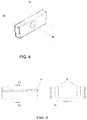
- the part can be screwed into the wall with one hand or with the aid of parts (8, 12) of Figures 4 and 7 .
- the flat part (8) contains a rectangular base (9) the length of which is equal to the inner diameter of the tubular part (1) and is provided with a surface suitable for gripping with the fingers (10).
- the flat part (8) is introduced inside the tubular part (1) and the tubular part (1) is tightened using the support points inside the tubular part.
- the part for a drill (12) of Figure 7 is formed by a shank (15) for being coupled to a drill chuck, and it comprises support means (13) for the tubular part formed by radial arms and ends in a centering pilot bit (14) marking and fixing the drilling point.
- the part (12) allows effortlessly screwing the parts in more quickly and without having to initially perforate the wall with a crown drill, particularly when the tubular part (1) has a serrated edge (11).
- the part for coupling to the drill needs at least two support points, and to improve the support, the part for a drill (12) and the tubular part (1) contain 4 support points as seen in detail in Figure 7 and Figure 1 .
- the tubular part (1), the receptacle (2) and the flat rectangular part (8) can be manufactured according to the methods known by the skilled person, for example by injection.
- the described system is primarily suitable for electrical conduits but it can also be used for gas, telecommunication or water conduits.
- the parts described in the invention can be manufactured from any material. If the system is going to be used for electrical boxes, the material must be an insulating material. In a preferred embodiment, the parts are manufactured from PVC or halogen-free thermoplastic ABS material.
- the tubular part described can be used as a support for hanging different objects: pictures or paintings, light fixtures, wall fittings, shelves, etc., furthermore making it easier to house elements or pass them through the wall by changing the diameter of the tubular part (1).
- the tubular part (1) is coupled to the wall and hook nails, eye bolts or hooks are placed in the channels (3). The attachment by means of the tubular part (1) prevents damage to the wall and allows hanging heavier objects.
- the tubular part allows the passage of installations, making connections or housing elements necessary for the light fixtures to operate.
Landscapes
- Engineering & Computer Science (AREA)
- Architecture (AREA)
- Civil Engineering (AREA)
- Structural Engineering (AREA)
- Power Engineering (AREA)
- Connection Of Plates (AREA)
- Connection Or Junction Boxes (AREA)
- Mechanical Engineering (AREA)
- Casings For Electric Apparatus (AREA)
Claims (10)
- Boîtier d'installation encastrable, comprenant :- une pièce tubulaire (1) ; et- un réceptacle (2) qui s'adapte à l'intérieur de la pièce tubulaire (1) ;où la pièce tubulaire (1) comprend :- une surface latérale extérieure contenant au moins une nervure (6) faisant saillie de ladite surface, traversant la surface latérale extérieure selon un trajet hélicoïdal pour permettre de visser ladite pièce tubulaire (1) dans une plaque de plâtre préfabriquée ; etdans laquelle ladite pièce tubulaire (1) permet le passage d'installations à travers celle-ci et le logement dans celle-ci d'éléments de raccordement ou de support ;
ledit boîtier d'installation encastrable caractérisé en ce que la pièce tubulaire (1) comprend une partie intérieure de la pièce tubulaire (1) contenant des moyens de support pour visser la pièce tubulaire (1) ; ladite partie intérieure de la pièce tubulaire (1) comprenant une partie supérieure qui correspond à la surface extérieure des moyens de support dans lesquels les vis ou les autres moyens de fixation sont placés et/ou où le réceptacle est introduit ; et
une partie inférieure contenant des saillies intérieures (7), dans laquelle la partie inférieure correspond à la face opposée à la partie supérieure de la partie interne de la pièce tubulaire (1) ; et en ce que le réceptacle (2) comprend une surface extérieure comprenant une partie supérieure ayant des saillies extérieures (5) qui sont limitées à la partie supérieure de la surface extérieure du réceptacle (2), dans lequel les saillies extérieures (5) du réceptacle (2) coïncident avec les saillies intérieures (7) de la partie tubulaire (1) lorsque le réceptacle (2) est emboîté dans la pièce tubulaire (1), permettant le déplacement du réceptacle (2) à l'intérieur de la pièce tubulaire (1) jusqu'à ce que les saillies intérieures (7) de la pièce tubulaire (1) entrent en contact avec les saillies extérieures (5) du réceptacle (2). - Boîtier d'installation encastrable selon la revendication 1, caractérisé en ce que les moyens de support comprennent au moins deux canaux (3) disposés longitudinalement.
- Boîtier d'installation encastrable selon la revendication 2, caractérisée en ce que les canaux (3) ont une longueur plus courte que la longueur de la pièce tubulaire (1) pour créer un rail (11).
- Boîtier d'installation encastrable selon la revendication 3, caractérisée en ce que le rail (11) permet au réceptacle (2) de tourner lorsqu'il est emboîté dans ladite pièce tubulaire (1).
- Boîtier d'installation encastrable selon l'une des revendications 1 à 4, caractérisé en ce qu'il comprend un bord inférieur dentelé (16).
- Boîtier d'installation encastrable selon l'une des revendications 2 à 3, caractérisé en ce que des vis sont insérées dans les canaux (3).
- Boîtier d'installation encastrable selon l'une des revendications 1 à 6, caractérisé en ce qu'il est fabriqué avec un matériau isolant.
- Boîtier d'installation encastrable selon l'une des revendications 1 à 7, caractérisé en ce que la nervure (6) s'étend sur au moins un tour et demi le long de la surface latérale extérieure.
- Boîtier d'installation encastrable selon la revendication 2, caractérisée en ce que des boulons à œil, des clous à crochet ou des crochets sont insérés dans les canaux (3).
- Boîtier d'installation encastrable selon l'une des revendications 1 à 9, caractérisé en ce que le réceptacle (2) comprend un socle contenant des points de rupture (4) qui permettent de créer des espaces dans ledit socle pour faciliter le passage du câble à travers celui-ci.
Applications Claiming Priority (2)
| Application Number | Priority Date | Filing Date | Title |
|---|---|---|---|
| ES201430591U ES1110605Y (es) | 2014-05-02 | 2014-05-02 | Piezas tubulares y cajas eléctricas encastrables. |
| PCT/ES2015/070357 WO2015166131A1 (fr) | 2014-05-02 | 2015-04-30 | Pièce tubulaire, boîtier électrique encastrable et kits constitués de ces derniers |
Publications (4)
| Publication Number | Publication Date |
|---|---|
| EP3139458A1 EP3139458A1 (fr) | 2017-03-08 |
| EP3139458A4 EP3139458A4 (fr) | 2017-04-19 |
| EP3139458B1 true EP3139458B1 (fr) | 2020-08-05 |
| EP3139458B8 EP3139458B8 (fr) | 2020-09-30 |
Family
ID=50774589
Family Applications (1)
| Application Number | Title | Priority Date | Filing Date |
|---|---|---|---|
| EP15785386.2A Active EP3139458B8 (fr) | 2014-05-02 | 2015-04-30 | Pièce tubulaire, boîtier électrique encastrable et kits constitués de ces derniers |
Country Status (5)
| Country | Link |
|---|---|
| US (1) | US9979171B2 (fr) |
| EP (1) | EP3139458B8 (fr) |
| CN (1) | CN106463922B (fr) |
| ES (2) | ES1110605Y (fr) |
| WO (1) | WO2015166131A1 (fr) |
Families Citing this family (5)
| Publication number | Priority date | Publication date | Assignee | Title |
|---|---|---|---|---|
| ES2685267B1 (es) | 2017-03-31 | 2019-07-17 | Iriarte Christian Gonzalez | Sistema de retención para uniones |
| US10323426B1 (en) | 2017-04-06 | 2019-06-18 | Kent Sandvig | Wall repair plug system |
| EP3660992A1 (fr) * | 2018-11-29 | 2020-06-03 | Hauff-Technik GmbH & Co. KG | Dispositif de boitier de raccordement |
| AT527717B1 (de) * | 2023-11-10 | 2025-07-15 | H4X Eu | Befestigungshohlelement, satz und anordnung |
| DE202023106677U1 (de) * | 2023-11-14 | 2023-12-19 | F-Tronic Gmbh | Befestigungshülse |
Citations (3)
| Publication number | Priority date | Publication date | Assignee | Title |
|---|---|---|---|---|
| ES1066154U (es) * | 2007-09-12 | 2007-12-16 | Asea Brown Boveri, S.A. | Caja para mecanismos electricos. |
| WO2012158628A2 (fr) * | 2011-05-13 | 2012-11-22 | Toyota Tsusho America, Inc. | Module del de grande puissance réutilisable et ses méthodes d'utilisation |
| US20130286667A1 (en) * | 2012-04-30 | 2013-10-31 | Qualcomm Mems Technologies, Inc. | Light fixtures and installation methods thereof |
Family Cites Families (14)
| Publication number | Priority date | Publication date | Assignee | Title |
|---|---|---|---|---|
| US3160458A (en) * | 1962-03-05 | 1964-12-08 | Hal Sandy Inc | Wall outlet |
| US4638115A (en) * | 1984-12-21 | 1987-01-20 | Butler Manufacturing Company | Three service afterset |
| US4883924A (en) * | 1988-07-20 | 1989-11-28 | Butler Manufacuting Company | Outlet fitting |
| FR2762941B1 (fr) | 1997-04-30 | 1999-07-30 | Legrand Sa | Boite d'encastrement pour cloison seche a patte(s) de serrage initialement d'un seul tenant, notamment pour appareillage electrique |
| US7064268B2 (en) * | 2004-09-22 | 2006-06-20 | Thomas & Betts International, Inc. | Floor box cover assembly |
| US7667136B2 (en) * | 2006-12-20 | 2010-02-23 | Thomas & Betts International, Inc. | Self cutting electrical outlet box |
| US7902459B2 (en) * | 2008-05-16 | 2011-03-08 | Harold Lehr | Junction box cover assembly |
| US8671702B1 (en) * | 2008-09-16 | 2014-03-18 | Hubbell Incorporated | Recessed thermostat and cutting tool |
| US8256728B2 (en) * | 2009-04-06 | 2012-09-04 | Wright Doug S | Speaker assemblies, methods of installing speaker assemblies and methods of making speaker assemblies |
| EP2273188B1 (fr) | 2009-07-06 | 2013-03-13 | Kaipo Chen | Dispositif d'éclairage avec capteur |
| CN202197067U (zh) * | 2011-08-16 | 2012-04-18 | 宁波金氏实业有限公司 | 墙体预埋接线盒 |
| BRPI1103720E2 (pt) * | 2011-11-11 | 2015-11-10 | Torniplast Artefatos Plásticos Ltda | caixa para tomada |
| GB2496630A (en) * | 2011-11-16 | 2013-05-22 | Electro Expo Ltd | Electrical socket apparatus set in wall opening |
| NL2008102C2 (nl) * | 2012-01-11 | 2013-07-15 | Abb Bv | Installatiedoos. |
-
2014
- 2014-05-02 ES ES201430591U patent/ES1110605Y/es not_active Expired - Fee Related
-
2015
- 2015-04-30 EP EP15785386.2A patent/EP3139458B8/fr active Active
- 2015-04-30 US US15/307,514 patent/US9979171B2/en active Active
- 2015-04-30 CN CN201580030258.9A patent/CN106463922B/zh active Active
- 2015-04-30 WO PCT/ES2015/070357 patent/WO2015166131A1/fr not_active Ceased
- 2015-04-30 ES ES15785386T patent/ES2829813T3/es active Active
Patent Citations (3)
| Publication number | Priority date | Publication date | Assignee | Title |
|---|---|---|---|---|
| ES1066154U (es) * | 2007-09-12 | 2007-12-16 | Asea Brown Boveri, S.A. | Caja para mecanismos electricos. |
| WO2012158628A2 (fr) * | 2011-05-13 | 2012-11-22 | Toyota Tsusho America, Inc. | Module del de grande puissance réutilisable et ses méthodes d'utilisation |
| US20130286667A1 (en) * | 2012-04-30 | 2013-10-31 | Qualcomm Mems Technologies, Inc. | Light fixtures and installation methods thereof |
Also Published As
| Publication number | Publication date |
|---|---|
| US9979171B2 (en) | 2018-05-22 |
| CN106463922B (zh) | 2020-01-14 |
| EP3139458A1 (fr) | 2017-03-08 |
| ES1110605Y (es) | 2014-08-20 |
| ES2829813T3 (es) | 2021-06-02 |
| US20170054281A1 (en) | 2017-02-23 |
| ES1110605U (es) | 2014-05-29 |
| WO2015166131A1 (fr) | 2015-11-05 |
| EP3139458A4 (fr) | 2017-04-19 |
| EP3139458B8 (fr) | 2020-09-30 |
| CN106463922A (zh) | 2017-02-22 |
Similar Documents
| Publication | Publication Date | Title |
|---|---|---|
| EP3139458B1 (fr) | Pièce tubulaire, boîtier électrique encastrable et kits constitués de ces derniers | |
| US6527302B1 (en) | Universal conduit body and system | |
| USRE47893E1 (en) | Conduit connector and methods for making and using the same | |
| GB2528391A (en) | Electrical connection system and method of installation | |
| US9431808B1 (en) | Electrical connector | |
| CN116753491A (zh) | 用于将悬吊式灯具悬挂于天花板的悬挂组件 | |
| US11732464B2 (en) | Securing assembly | |
| US9490618B2 (en) | Electrical splice box | |
| US20200032955A1 (en) | Apparatuses Including Fixtures and/or Fixture Mounts and Related Methods | |
| US10578286B2 (en) | Device for the connection of electrical luminaires with fault current diversion | |
| KR101774826B1 (ko) | 케이블 분기 포설용 케이블 트레이 시스템 | |
| US11306757B2 (en) | Swing arm for recessed lighting fixtures | |
| US20210126444A1 (en) | Installation apparatus consisting of a wall plug and a holder which can be screwed therein for installing flush-mounted devices | |
| EP3021440A1 (fr) | Dispositif de connexion pour un dispositif électrique | |
| CN109149466B (zh) | 穿线盒 | |
| CA2853404C (fr) | Raccords de conduite et procedes pour fabriquer et utiliser ceux-ci | |
| US10348070B1 (en) | Kit for running wire and cable | |
| KR20150049055A (ko) | 천정용 전기박스 | |
| KR101140842B1 (ko) | 천정매입형 형광등 장착용 프레임 | |
| US9899820B1 (en) | Wall plate | |
| CA2821441C (fr) | Connecteur electrique | |
| KR200330358Y1 (ko) | 안내판 고정구 | |
| KR101705451B1 (ko) | 수중함 갑판용 핸드레일 | |
| SE539503C2 (sv) | A grounding attachment and a pole provided with such a grounding attachment | |
| SE540404C2 (en) | A grounding attachment and a pole provided with such a grounding attachment |
Legal Events
| Date | Code | Title | Description |
|---|---|---|---|
| STAA | Information on the status of an ep patent application or granted ep patent |
Free format text: STATUS: THE INTERNATIONAL PUBLICATION HAS BEEN MADE |
|
| PUAI | Public reference made under article 153(3) epc to a published international application that has entered the european phase |
Free format text: ORIGINAL CODE: 0009012 |
|
| STAA | Information on the status of an ep patent application or granted ep patent |
Free format text: STATUS: REQUEST FOR EXAMINATION WAS MADE |
|
| 17P | Request for examination filed |
Effective date: 20161129 |
|
| AK | Designated contracting states |
Kind code of ref document: A1 Designated state(s): AL AT BE BG CH CY CZ DE DK EE ES FI FR GB GR HR HU IE IS IT LI LT LU LV MC MK MT NL NO PL PT RO RS SE SI SK SM TR |
|
| AX | Request for extension of the european patent |
Extension state: BA ME |
|
| A4 | Supplementary search report drawn up and despatched |
Effective date: 20170317 |
|
| RIC1 | Information provided on ipc code assigned before grant |
Ipc: B23B 51/04 20060101ALI20170313BHEP Ipc: H02G 3/22 20060101ALI20170313BHEP Ipc: H02G 3/12 20060101ALI20170313BHEP Ipc: H02B 1/46 20060101AFI20170313BHEP |
|
| DAV | Request for validation of the european patent (deleted) | ||
| DAX | Request for extension of the european patent (deleted) | ||
| STAA | Information on the status of an ep patent application or granted ep patent |
Free format text: STATUS: EXAMINATION IS IN PROGRESS |
|
| 17Q | First examination report despatched |
Effective date: 20171116 |
|
| GRAP | Despatch of communication of intention to grant a patent |
Free format text: ORIGINAL CODE: EPIDOSNIGR1 |
|
| STAA | Information on the status of an ep patent application or granted ep patent |
Free format text: STATUS: GRANT OF PATENT IS INTENDED |
|
| INTG | Intention to grant announced |
Effective date: 20200316 |
|
| GRAS | Grant fee paid |
Free format text: ORIGINAL CODE: EPIDOSNIGR3 |
|
| GRAA | (expected) grant |
Free format text: ORIGINAL CODE: 0009210 |
|
| STAA | Information on the status of an ep patent application or granted ep patent |
Free format text: STATUS: THE PATENT HAS BEEN GRANTED |
|
| AK | Designated contracting states |
Kind code of ref document: B1 Designated state(s): AL AT BE BG CH CY CZ DE DK EE ES FI FR GB GR HR HU IE IS IT LI LT LU LV MC MK MT NL NO PL PT RO RS SE SI SK SM TR |
|
| REG | Reference to a national code |
Ref country code: GB Ref legal event code: FG4D |
|
| RAP2 | Party data changed (patent owner data changed or rights of a patent transferred) |
Owner name: WOW MAKERS, S.L. |
|
| RIN2 | Information on inventor provided after grant (corrected) |
Inventor name: CEREZO CANDELA, RUBEN Inventor name: LOPEZ RUBIO, SEBASTIAN |
|
| REG | Reference to a national code |
Ref country code: CH Ref legal event code: EP |
|
| REG | Reference to a national code |
Ref country code: AT Ref legal event code: REF Ref document number: 1300058 Country of ref document: AT Kind code of ref document: T Effective date: 20200815 |
|
| REG | Reference to a national code |
Ref country code: DE Ref legal event code: R096 Ref document number: 602015057000 Country of ref document: DE |
|
| REG | Reference to a national code |
Ref country code: IE Ref legal event code: FG4D |
|
| REG | Reference to a national code |
Ref country code: CH Ref legal event code: PK Free format text: BERICHTIGUNG B8 |
|
| REG | Reference to a national code |
Ref country code: CH Ref legal event code: PK Free format text: BERICHTIGUNGEN |
|
| RIN2 | Information on inventor provided after grant (corrected) |
Inventor name: CEREZO CANDELA, RUBEN Inventor name: LOPEZ RUBIO, SEBASTIAN |
|
| REG | Reference to a national code |
Ref country code: LT Ref legal event code: MG4D |
|
| REG | Reference to a national code |
Ref country code: NL Ref legal event code: MP Effective date: 20200805 |
|
| REG | Reference to a national code |
Ref country code: AT Ref legal event code: MK05 Ref document number: 1300058 Country of ref document: AT Kind code of ref document: T Effective date: 20200805 |
|
| PG25 | Lapsed in a contracting state [announced via postgrant information from national office to epo] |
Ref country code: GR Free format text: LAPSE BECAUSE OF FAILURE TO SUBMIT A TRANSLATION OF THE DESCRIPTION OR TO PAY THE FEE WITHIN THE PRESCRIBED TIME-LIMIT Effective date: 20201106 Ref country code: NO Free format text: LAPSE BECAUSE OF FAILURE TO SUBMIT A TRANSLATION OF THE DESCRIPTION OR TO PAY THE FEE WITHIN THE PRESCRIBED TIME-LIMIT Effective date: 20201105 Ref country code: AT Free format text: LAPSE BECAUSE OF FAILURE TO SUBMIT A TRANSLATION OF THE DESCRIPTION OR TO PAY THE FEE WITHIN THE PRESCRIBED TIME-LIMIT Effective date: 20200805 Ref country code: PT Free format text: LAPSE BECAUSE OF FAILURE TO SUBMIT A TRANSLATION OF THE DESCRIPTION OR TO PAY THE FEE WITHIN THE PRESCRIBED TIME-LIMIT Effective date: 20201207 Ref country code: LT Free format text: LAPSE BECAUSE OF FAILURE TO SUBMIT A TRANSLATION OF THE DESCRIPTION OR TO PAY THE FEE WITHIN THE PRESCRIBED TIME-LIMIT Effective date: 20200805 Ref country code: BG Free format text: LAPSE BECAUSE OF FAILURE TO SUBMIT A TRANSLATION OF THE DESCRIPTION OR TO PAY THE FEE WITHIN THE PRESCRIBED TIME-LIMIT Effective date: 20201105 Ref country code: FI Free format text: LAPSE BECAUSE OF FAILURE TO SUBMIT A TRANSLATION OF THE DESCRIPTION OR TO PAY THE FEE WITHIN THE PRESCRIBED TIME-LIMIT Effective date: 20200805 Ref country code: HR Free format text: LAPSE BECAUSE OF FAILURE TO SUBMIT A TRANSLATION OF THE DESCRIPTION OR TO PAY THE FEE WITHIN THE PRESCRIBED TIME-LIMIT Effective date: 20200805 Ref country code: SE Free format text: LAPSE BECAUSE OF FAILURE TO SUBMIT A TRANSLATION OF THE DESCRIPTION OR TO PAY THE FEE WITHIN THE PRESCRIBED TIME-LIMIT Effective date: 20200805 |
|
| PG25 | Lapsed in a contracting state [announced via postgrant information from national office to epo] |
Ref country code: RS Free format text: LAPSE BECAUSE OF FAILURE TO SUBMIT A TRANSLATION OF THE DESCRIPTION OR TO PAY THE FEE WITHIN THE PRESCRIBED TIME-LIMIT Effective date: 20200805 Ref country code: LV Free format text: LAPSE BECAUSE OF FAILURE TO SUBMIT A TRANSLATION OF THE DESCRIPTION OR TO PAY THE FEE WITHIN THE PRESCRIBED TIME-LIMIT Effective date: 20200805 Ref country code: PL Free format text: LAPSE BECAUSE OF FAILURE TO SUBMIT A TRANSLATION OF THE DESCRIPTION OR TO PAY THE FEE WITHIN THE PRESCRIBED TIME-LIMIT Effective date: 20200805 Ref country code: NL Free format text: LAPSE BECAUSE OF FAILURE TO SUBMIT A TRANSLATION OF THE DESCRIPTION OR TO PAY THE FEE WITHIN THE PRESCRIBED TIME-LIMIT Effective date: 20200805 Ref country code: IS Free format text: LAPSE BECAUSE OF FAILURE TO SUBMIT A TRANSLATION OF THE DESCRIPTION OR TO PAY THE FEE WITHIN THE PRESCRIBED TIME-LIMIT Effective date: 20201205 |
|
| PG25 | Lapsed in a contracting state [announced via postgrant information from national office to epo] |
Ref country code: EE Free format text: LAPSE BECAUSE OF FAILURE TO SUBMIT A TRANSLATION OF THE DESCRIPTION OR TO PAY THE FEE WITHIN THE PRESCRIBED TIME-LIMIT Effective date: 20200805 Ref country code: SM Free format text: LAPSE BECAUSE OF FAILURE TO SUBMIT A TRANSLATION OF THE DESCRIPTION OR TO PAY THE FEE WITHIN THE PRESCRIBED TIME-LIMIT Effective date: 20200805 Ref country code: RO Free format text: LAPSE BECAUSE OF FAILURE TO SUBMIT A TRANSLATION OF THE DESCRIPTION OR TO PAY THE FEE WITHIN THE PRESCRIBED TIME-LIMIT Effective date: 20200805 Ref country code: DK Free format text: LAPSE BECAUSE OF FAILURE TO SUBMIT A TRANSLATION OF THE DESCRIPTION OR TO PAY THE FEE WITHIN THE PRESCRIBED TIME-LIMIT Effective date: 20200805 Ref country code: CZ Free format text: LAPSE BECAUSE OF FAILURE TO SUBMIT A TRANSLATION OF THE DESCRIPTION OR TO PAY THE FEE WITHIN THE PRESCRIBED TIME-LIMIT Effective date: 20200805 |
|
| REG | Reference to a national code |
Ref country code: DE Ref legal event code: R097 Ref document number: 602015057000 Country of ref document: DE |
|
| PG25 | Lapsed in a contracting state [announced via postgrant information from national office to epo] |
Ref country code: AL Free format text: LAPSE BECAUSE OF FAILURE TO SUBMIT A TRANSLATION OF THE DESCRIPTION OR TO PAY THE FEE WITHIN THE PRESCRIBED TIME-LIMIT Effective date: 20200805 |
|
| REG | Reference to a national code |
Ref country code: ES Ref legal event code: FG2A Ref document number: 2829813 Country of ref document: ES Kind code of ref document: T3 Effective date: 20210602 |
|
| PLBE | No opposition filed within time limit |
Free format text: ORIGINAL CODE: 0009261 |
|
| STAA | Information on the status of an ep patent application or granted ep patent |
Free format text: STATUS: NO OPPOSITION FILED WITHIN TIME LIMIT |
|
| PG25 | Lapsed in a contracting state [announced via postgrant information from national office to epo] |
Ref country code: SK Free format text: LAPSE BECAUSE OF FAILURE TO SUBMIT A TRANSLATION OF THE DESCRIPTION OR TO PAY THE FEE WITHIN THE PRESCRIBED TIME-LIMIT Effective date: 20200805 |
|
| 26N | No opposition filed |
Effective date: 20210507 |
|
| PG25 | Lapsed in a contracting state [announced via postgrant information from national office to epo] |
Ref country code: IT Free format text: LAPSE BECAUSE OF FAILURE TO SUBMIT A TRANSLATION OF THE DESCRIPTION OR TO PAY THE FEE WITHIN THE PRESCRIBED TIME-LIMIT Effective date: 20200805 |
|
| PG25 | Lapsed in a contracting state [announced via postgrant information from national office to epo] |
Ref country code: SI Free format text: LAPSE BECAUSE OF FAILURE TO SUBMIT A TRANSLATION OF THE DESCRIPTION OR TO PAY THE FEE WITHIN THE PRESCRIBED TIME-LIMIT Effective date: 20200805 |
|
| PG25 | Lapsed in a contracting state [announced via postgrant information from national office to epo] |
Ref country code: MC Free format text: LAPSE BECAUSE OF FAILURE TO SUBMIT A TRANSLATION OF THE DESCRIPTION OR TO PAY THE FEE WITHIN THE PRESCRIBED TIME-LIMIT Effective date: 20200805 |
|
| PG25 | Lapsed in a contracting state [announced via postgrant information from national office to epo] |
Ref country code: LU Free format text: LAPSE BECAUSE OF NON-PAYMENT OF DUE FEES Effective date: 20210430 |
|
| REG | Reference to a national code |
Ref country code: BE Ref legal event code: MM Effective date: 20210430 |
|
| PG25 | Lapsed in a contracting state [announced via postgrant information from national office to epo] |
Ref country code: CH Free format text: LAPSE BECAUSE OF NON-PAYMENT OF DUE FEES Effective date: 20210430 Ref country code: LI Free format text: LAPSE BECAUSE OF NON-PAYMENT OF DUE FEES Effective date: 20210430 |
|
| PG25 | Lapsed in a contracting state [announced via postgrant information from national office to epo] |
Ref country code: IE Free format text: LAPSE BECAUSE OF NON-PAYMENT OF DUE FEES Effective date: 20210430 |
|
| PG25 | Lapsed in a contracting state [announced via postgrant information from national office to epo] |
Ref country code: IS Free format text: LAPSE BECAUSE OF FAILURE TO SUBMIT A TRANSLATION OF THE DESCRIPTION OR TO PAY THE FEE WITHIN THE PRESCRIBED TIME-LIMIT Effective date: 20201205 |
|
| PG25 | Lapsed in a contracting state [announced via postgrant information from national office to epo] |
Ref country code: BE Free format text: LAPSE BECAUSE OF NON-PAYMENT OF DUE FEES Effective date: 20210430 |
|
| PG25 | Lapsed in a contracting state [announced via postgrant information from national office to epo] |
Ref country code: HU Free format text: LAPSE BECAUSE OF FAILURE TO SUBMIT A TRANSLATION OF THE DESCRIPTION OR TO PAY THE FEE WITHIN THE PRESCRIBED TIME-LIMIT; INVALID AB INITIO Effective date: 20150430 |
|
| PG25 | Lapsed in a contracting state [announced via postgrant information from national office to epo] |
Ref country code: CY Free format text: LAPSE BECAUSE OF FAILURE TO SUBMIT A TRANSLATION OF THE DESCRIPTION OR TO PAY THE FEE WITHIN THE PRESCRIBED TIME-LIMIT Effective date: 20200805 |
|
| PG25 | Lapsed in a contracting state [announced via postgrant information from national office to epo] |
Ref country code: MK Free format text: LAPSE BECAUSE OF FAILURE TO SUBMIT A TRANSLATION OF THE DESCRIPTION OR TO PAY THE FEE WITHIN THE PRESCRIBED TIME-LIMIT Effective date: 20200805 |
|
| PG25 | Lapsed in a contracting state [announced via postgrant information from national office to epo] |
Ref country code: TR Free format text: LAPSE BECAUSE OF FAILURE TO SUBMIT A TRANSLATION OF THE DESCRIPTION OR TO PAY THE FEE WITHIN THE PRESCRIBED TIME-LIMIT Effective date: 20200805 |
|
| PGFP | Annual fee paid to national office [announced via postgrant information from national office to epo] |
Ref country code: ES Payment date: 20240508 Year of fee payment: 10 |
|
| PG25 | Lapsed in a contracting state [announced via postgrant information from national office to epo] |
Ref country code: MT Free format text: LAPSE BECAUSE OF FAILURE TO SUBMIT A TRANSLATION OF THE DESCRIPTION OR TO PAY THE FEE WITHIN THE PRESCRIBED TIME-LIMIT Effective date: 20200805 |
|
| PGFP | Annual fee paid to national office [announced via postgrant information from national office to epo] |
Ref country code: DE Payment date: 20250429 Year of fee payment: 11 |
|
| PGFP | Annual fee paid to national office [announced via postgrant information from national office to epo] |
Ref country code: GB Payment date: 20250423 Year of fee payment: 11 |
|
| PGFP | Annual fee paid to national office [announced via postgrant information from national office to epo] |
Ref country code: FR Payment date: 20250425 Year of fee payment: 11 |