EP3139635A1 - Synchronisierung von audioströmen und abtastrate für drahtlose kommunikation - Google Patents
Synchronisierung von audioströmen und abtastrate für drahtlose kommunikation Download PDFInfo
- Publication number
- EP3139635A1 EP3139635A1 EP16186053.1A EP16186053A EP3139635A1 EP 3139635 A1 EP3139635 A1 EP 3139635A1 EP 16186053 A EP16186053 A EP 16186053A EP 3139635 A1 EP3139635 A1 EP 3139635A1
- Authority
- EP
- European Patent Office
- Prior art keywords
- outgoing
- src
- sample
- incoming
- packet
- Prior art date
- Legal status (The legal status is an assumption and is not a legal conclusion. Google has not performed a legal analysis and makes no representation as to the accuracy of the status listed.)
- Ceased
Links
Images


Classifications
-
- H—ELECTRICITY
- H04—ELECTRIC COMMUNICATION TECHNIQUE
- H04W—WIRELESS COMMUNICATION NETWORKS
- H04W56/00—Synchronisation arrangements
- H04W56/001—Synchronization between nodes
-
- G—PHYSICS
- G10—MUSICAL INSTRUMENTS; ACOUSTICS
- G10H—ELECTROPHONIC MUSICAL INSTRUMENTS; INSTRUMENTS IN WHICH THE TONES ARE GENERATED BY ELECTROMECHANICAL MEANS OR ELECTRONIC GENERATORS, OR IN WHICH THE TONES ARE SYNTHESISED FROM A DATA STORE
- G10H1/00—Details of electrophonic musical instruments
- G10H1/0033—Recording/reproducing or transmission of music for electrophonic musical instruments
- G10H1/0083—Recording/reproducing or transmission of music for electrophonic musical instruments using wireless transmission, e.g. radio, light, infrared
-
- H—ELECTRICITY
- H04—ELECTRIC COMMUNICATION TECHNIQUE
- H04L—TRANSMISSION OF DIGITAL INFORMATION, e.g. TELEGRAPHIC COMMUNICATION
- H04L47/00—Traffic control in data switching networks
- H04L47/10—Flow control; Congestion control
- H04L47/30—Flow control; Congestion control in combination with information about buffer occupancy at either end or at transit nodes
-
- H—ELECTRICITY
- H04—ELECTRIC COMMUNICATION TECHNIQUE
- H04R—LOUDSPEAKERS, MICROPHONES, GRAMOPHONE PICK-UPS OR LIKE ACOUSTIC ELECTROMECHANICAL TRANSDUCERS; ELECTRIC HEARING AIDS; PUBLIC ADDRESS SYSTEMS
- H04R25/00—Electric hearing aids
- H04R25/55—Electric hearing aids using an external connection, either wireless or wired
- H04R25/552—Binaural
-
- H—ELECTRICITY
- H04—ELECTRIC COMMUNICATION TECHNIQUE
- H04R—LOUDSPEAKERS, MICROPHONES, GRAMOPHONE PICK-UPS OR LIKE ACOUSTIC ELECTROMECHANICAL TRANSDUCERS; ELECTRIC HEARING AIDS; PUBLIC ADDRESS SYSTEMS
- H04R25/00—Electric hearing aids
- H04R25/55—Electric hearing aids using an external connection, either wireless or wired
- H04R25/554—Electric hearing aids using an external connection, either wireless or wired using a wireless connection, e.g. between microphone and amplifier or using Tcoils
-
- H—ELECTRICITY
- H04—ELECTRIC COMMUNICATION TECHNIQUE
- H04W—WIRELESS COMMUNICATION NETWORKS
- H04W56/00—Synchronisation arrangements
- H04W56/004—Synchronisation arrangements compensating for timing error of reception due to propagation delay
-
- G—PHYSICS
- G10—MUSICAL INSTRUMENTS; ACOUSTICS
- G10H—ELECTROPHONIC MUSICAL INSTRUMENTS; INSTRUMENTS IN WHICH THE TONES ARE GENERATED BY ELECTROMECHANICAL MEANS OR ELECTRONIC GENERATORS, OR IN WHICH THE TONES ARE SYNTHESISED FROM A DATA STORE
- G10H2240/00—Data organisation or data communication aspects, specifically adapted for electrophonic musical tools or instruments
- G10H2240/325—Synchronizing two or more audio tracks or files according to musical features or musical timings
-
- G—PHYSICS
- G10—MUSICAL INSTRUMENTS; ACOUSTICS
- G10H—ELECTROPHONIC MUSICAL INSTRUMENTS; INSTRUMENTS IN WHICH THE TONES ARE GENERATED BY ELECTROMECHANICAL MEANS OR ELECTRONIC GENERATORS, OR IN WHICH THE TONES ARE SYNTHESISED FROM A DATA STORE
- G10H2250/00—Aspects of algorithms or signal processing methods without intrinsic musical character, yet specifically adapted for or used in electrophonic musical processing
- G10H2250/541—Details of musical waveform synthesis, i.e. audio waveshape processing from individual wavetable samples, independently of their origin or of the sound they represent
- G10H2250/631—Waveform resampling, i.e. sample rate conversion or sample depth conversion
-
- H—ELECTRICITY
- H03—ELECTRONIC CIRCUITRY
- H03H—IMPEDANCE NETWORKS, e.g. RESONANT CIRCUITS; RESONATORS
- H03H17/00—Networks using digital techniques
- H03H17/0009—Time-delay networks
- H03H17/0018—Realizing a fractional delay
-
- H—ELECTRICITY
- H03—ELECTRONIC CIRCUITRY
- H03H—IMPEDANCE NETWORKS, e.g. RESONANT CIRCUITS; RESONATORS
- H03H17/00—Networks using digital techniques
- H03H17/02—Frequency selective networks
- H03H17/06—Non-recursive filters
- H03H17/0621—Non-recursive filters with input-sampling frequency and output-delivery frequency which differ, e.g. extrapolation; Anti-aliasing
- H03H17/0635—Non-recursive filters with input-sampling frequency and output-delivery frequency which differ, e.g. extrapolation; Anti-aliasing characterized by the ratio between the input-sampling and output-delivery frequencies
- H03H17/0642—Non-recursive filters with input-sampling frequency and output-delivery frequency which differ, e.g. extrapolation; Anti-aliasing characterized by the ratio between the input-sampling and output-delivery frequencies the ratio being arbitrary or irrational
-
- H—ELECTRICITY
- H04—ELECTRIC COMMUNICATION TECHNIQUE
- H04L—TRANSMISSION OF DIGITAL INFORMATION, e.g. TELEGRAPHIC COMMUNICATION
- H04L12/00—Data switching networks
- H04L12/54—Store-and-forward switching systems
- H04L12/56—Packet switching systems
- H04L12/5601—Transfer mode dependent, e.g. ATM
- H04L2012/5678—Traffic aspects, e.g. arbitration, load balancing, smoothing, buffer management
- H04L2012/5681—Buffer or queue management
-
- H—ELECTRICITY
- H04—ELECTRIC COMMUNICATION TECHNIQUE
- H04L—TRANSMISSION OF DIGITAL INFORMATION, e.g. TELEGRAPHIC COMMUNICATION
- H04L47/00—Traffic control in data switching networks
- H04L47/10—Flow control; Congestion control
- H04L47/26—Flow control; Congestion control using explicit feedback to the source, e.g. choke packets
- H04L47/263—Rate modification at the source after receiving feedback
-
- H—ELECTRICITY
- H04—ELECTRIC COMMUNICATION TECHNIQUE
- H04R—LOUDSPEAKERS, MICROPHONES, GRAMOPHONE PICK-UPS OR LIKE ACOUSTIC ELECTROMECHANICAL TRANSDUCERS; ELECTRIC HEARING AIDS; PUBLIC ADDRESS SYSTEMS
- H04R2225/00—Details of deaf aids covered by H04R25/00, not provided for in any of its subgroups
- H04R2225/55—Communication between hearing aids and external devices via a network for data exchange
Definitions
- the present subject matter relates generally to wireless communication, and in particular to synchronization for audio streaming of wireless communication.
- Wireless communication is used for a variety of applications, including for use with hearing assistance devices.
- Modern hearing assistance devices typically include digital electronics to enhance the wearer's experience.
- current designs employ digital signal processors rich in features. Their functionality is further benefited from communications, either from a remote source or from ear-to-ear for advanced processing.
- wireless functionality for a hearing aid to allow for functions such as ear to ear synchronization, remote control, programming and configuration, streaming audio, bi-directional audio, etc.
- the present subject matter can be used for any wireless communication system, including but not limited to hearing assistance device applications.
- a method for wireless communications includes receiving a transmission of a packet using a wireless transceiver of an electronic device, and using a processor of the electronic device to read a first value of a system timer and store the first value as an arrival time-stamp.
- the packet is decoded and processed by the processor, and sent to an output.
- a second value of the system timer is read, adjusted and stored as a departure time-stamp.
- the arrival time-stamp and the departure time-stamp are used to calculate an adjustment stimulus for a sample rate actuator of the electronic device.
- the sample rate actuator is configured to maintain synchronization of sampling rate with an external packet rate.
- a method for bidirectional wireless communications includes receiving a transmission of a packet using a wireless transceiver of an electronic device, and calculating an incoming fractional delay (FD) using a FD sampling rate converter (SRC), where the FD SRC configured to synchronize sample rate of the device with an external packet rate.
- the incoming FD and current phase increment value of the FD SRC are used to calculate an outgoing FD, to provide a one-to-one relation between incoming and outgoing packets for the device.
- Modern portable wireless communication equipment employs radio communications for various uses, some of which include the transmission of data such as audio and video data. Such communication utilizes highly reliable data networks capable of low packet and bit error rates.
- a wireless host can be the source of the audio or video information.
- Portable electronic devices such as headsets, hearing aids, head worn displays and the like can send and receive wireless communication.
- Hearing assistance devices are only one type of hearing assistance device.
- Other hearing assistance devices include, but are not limited to, those in this document. It is understood that their use in the description is intended to demonstrate the present subject matter, but not in a limited or exclusive or exhaustive sense.
- the present subject matter can be used for implementation of such features as a television (TV) streamer or for cellular phone/entertainment device (CPED) audio streaming, ear-to-ear streaming and CROS/BiCROS (Contra Lateral Routing of Signal (CROS) is a hearing aid technology for people with unilateral hearing), and uses of synchronization of audio input or output sampling rate with external packet rate.
- TV television
- CPED cellular phone/entertainment device
- CROS/BiCROS Consumer Lateral Routing of Signal
- source sampling rate is slightly higher than sink sampling rate.
- the audio samples will be accumulated in the sink buffer faster than samples are consumed from it. Eventually, this will result in overflow of the sink buffer and result in artifacts in the audio stream.
- device delay of the sink increases as each samples "spends" more time in the sink buffer. Device delay will remain the same only in the case where the sampling frequencies of the source and the sink are perfectly identical.
- the present subject matter measures the device delay and maintains it constant by adjusting the effective sampling rate of the device.
- time-stamps of the moments when samples enter and leave the device are measured and in some instances calculated.
- two time-stamps, one of the sample's entry moment and one of the sample's leave moment are input as data to the feedback loop controller.
- Its output data is a control signal which adjusts the effective sampling rate of the device, as shown in the FIGS. 2-7 below.
- the present subject matter provides great flexibility and can be used with many different devices (source, sink, relay or combined) with different internal architectures. For example, it is applicable to devices where the packet reception and processing of audio samples are carried out by different central processing unit (CPU) cores.
- CPU central processing unit
- a processing chip contains two CPU cores: CM3 and CFX. Reception of streaming radio packets is performed by CM3 firmware and therefore all packet timing is originally available for CM3.
- CFX firmware includes a Sample Rate Converter (SRC), which is used to adjust the effective sampling rate. The re-sampled audio stream is then sent to the output DAC.
- SRC Sample Rate Converter
- the main difference of the present subject matter is that it has the ability to measure the device delay and maintain it equal to a preconfigured value much more accurately.
- the present subject matter maintains variations of device delay of an audio stream constant close to its preconfigured value with accuracy (absolute value and variations) better than 10 microseconds, in an embodiment.
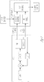
- FIG. 2 illustrates a block diagram for sink sample rate synchronization, according to various embodiments of the present subject matter. This present subject matter provides for sample rate synchronization of the sink, in various embodiments, as illustrated in FIG. 2 . Applications for other elements of the audio streaming system (source, relay, etc.) are discussed below.
- samples are transmitted over the communication channel in packets. It is assumed that the moment of start (or end) of packet reception can be time-stamped with high accuracy by reading a timer value from the associated firmware code, e.g. interrupt service routine (ISR) of the direct memory access (DMA) channel between CPU and radio chip.
- ISR interrupt service routine
- DMA direct memory access
- FIG. 2 a received packet is transferred from the Radio Rx subsystem to the system CPU through a DMA channel or equivalent buffer mechanism. Completion of the packet DMA transfer triggers a Radio DMA ISR.
- the radio DMA ISR reads the current value of the sink system timer and optionally processes it to reduce jitter and stores as an "arrival time-stamp", in various embodiments.
- this time-stamp is associated with the first audio sample in the packet.
- Packet audio samples are then decoded and processed by the audio processing system shown in FIG. 2 as "processing stages".
- the processed samples of the audio stream are transferred to the output, e.g. DAC.
- the moment of the output of the first sample of the packet is time-stamped.
- the exact method of time-stamping of the first sample depends on the implementation of the audio stream output. In the example from FIG. 2 , the output from the CPU to DAC is handled by DMA channel 2. Completion of the DMA transfer triggers DMA2 ISR.
- DMA2 ISR reads current value of the sink system timer then, if necessary, performs adjustment of the timer value as discussed below and stores it as a "departure time-stamp".
- the arrival and departure time-stamps are used as input data for the feedback loop controller.
- the error value is then used to calculate an adjustment stimulus for the sample rate actuator using one of algorithms discussed in process control theory, e.g. a proportional-integral-derivative (PID) controller algorithm.
- PID proportional-integral-derivative
- FIG. 3 illustrates a combination of both.
- the upper row shown in FIG. 3 represents samples before FD SRC.
- Arrival timestamp of the first sample of packet n has been recorded at Radio DMA ISR as described in FIG. 3 .
- the lower row represents samples after FD SRC.
- These samples are transferred to DAC by DAC DMA 8 samples per block.
- the timestamp of a first sample of block k is recorded by DAC DMA ISR for block k.
- DAC DMA ISR is triggered at the completion of block transfer.
- the preconfigured value for the device group delay should be minimal, but sufficient to accommodate the longest branch of the signal processing scheme. If the signal processing scheme changes (e.g. different type of codec has been selected or packet loss concealment mechanism has been enabled or disabled), this value can be reconfigured to optimize system total throughput delay.
- Various embodiments create an artificial intelligence (AI) system, which can track processing time over the different branches of the processing scheme and automatically reconfigure the value of the device group delay in order to minimize total system throughput delay.
- AI artificial intelligence
- a preconfigured value of device group delay time must be synchronized between receivers of the left and right channels.
- FIG. 4 illustrates a block diagram for synchronization of the sampling rate of a source device, according to various embodiments of the present subject matter.
- a scenario for synchronization of the sampling rate of the source device is shown in FIG. 4 .
- the packet rate is driven by an external device (packet requests from Radio Tx as shown in FIG. 4 ) where the audio sampling rate is derived from a local oscillator.
- the source sampling rate synchronization is mirror symmetric to the synchronization of the sink scenario as shown in FIG. 2 .
- ⁇ inc T samp ⁇ 1 ⁇ TD i ⁇ TD i ⁇ 1 N samp + ⁇ ⁇ Error
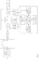
- FIG. 5 illustrates a block diagram of synchronization of the sampling rate of source and sink devices, according to various embodiments of the present subject matter. Since SysClk equally affects the source and sink sampling rate, only one adjustment stimulus needs to be calculated by the feedback loop controller in case where SysClk is used as a sample rate actuator.
- phase increment values need to be calculated: for sink and source FD SRC instances (Rx FD SRC and Tx FD SRC in FIG. 5 ). Calculation of phase increment is done by using formulas provided above for Sink and Source devices.
- the relay device forwards packets received from the input wireless link (Rx Link in FIG. 5 ) to the output wireless link (Tx Link in FIG. 5 ).
- packet rates of Rx Link and Tx Link are synchronized (e.g. TDMA channel with Rx and Tx time slots)
- no sample rate synchronization is needed.
- Rx Link and Tx Link are asynchronous, their synchronization can be realized on the relay device by synchronization of the sampling rate.
- FIG. 6 illustrates a block diagram of synchronization of the sampling rate of a relay device, according to various embodiments of the present subject matter. Since the relay does not use an input/output device, the sampling rate of which can be adjusted by software, SysClk cannot be used as a sampling rate actuator. In FIG. 6 , FD SRC is used as a sample rate actuator.
- bidirectional audio streaming is used to support phone calls via hearing aid devices linked with a Cell Phone / Entertainment Device (CPED).
- CPED Cell Phone / Entertainment Device
- Two-way communication between the hearing aid devices and the CPED is performed using TDD with two time slots as show in FIG. 9 .
- TDD Time Division Duplex
- the number of incoming and outgoing audio samples over packet period is locked.
- incoming and outgoing audio streams are synchronized in order to avoid buffers overflow or underflow as well as noticeable audio artifacts.
- the present subject matter firmly synchronizes the number of incoming and outgoing samples per packet period without distorting quality of the audio stream.
- the method described herein is applicable to a system where a FD SRC is used for synchronization of the device sample rate with external packet rate.
- the idea of the method is to generate one outgoing sample for each consumed incoming sample. As it is shown in FIG. 1 , to generate a new sample by the FD SRC interpolator the following parameters are used:
- FIG. 5 A block diagram of a previous implementation of a device with bidirectional audio streaming is shown in FIG. 5 .
- the device is of sink / source type, and the consumed (sink) audio stream is "incoming" and generated (source) audio stream is "outgoing".
- sink_ ⁇ inc The value of sink_ ⁇ inc is calculated and then source_ ⁇ inc is calculated as a reciprocal.
- the problem is that in this case only the formula for source_ ⁇ inc contains the feedback term and the formula for source_ ⁇ inc does not.
- device latency for the outgoing audio stream will vary (e.g. due to limited accuracy of computations) and such variation will not be compensated.
- FIG. 8 illustrates a block diagram of a bidirectional FD SRC with independent incoming and outgoing channels, according to various embodiments of the present subject matter.
- Bidirectional audio streaming is performed via TDD channel with two timeslots: for the incoming and outgoing audio streams packets as shown in FIG. 9 .
- the number of generated outgoing samples within one packet period is equal to the number of samples in the packet. Variation of the device audio latency for the outgoing stream may eventually result in underflow or overflow of the outgoing output buffer.
- the system clock rate of the sink device was selected so that the sampling rate of the sink was as close as possible to the sampling rate of the source but above it.
- the number of samples received in one packet was equal or less than number of samples sent to the output in the packet period. If number of samples was less than required, zeros were inserted instead of missing samples. Typically, one zero sample was inserted after a few packets.
- the number of samples generated by the source in one packet period was equal to more than the number of samples. As a result, one of samples was occasionally discarded. Of course, inserting zeros and dropping "extra" samples resulted in audible distortions of the incoming and outgoing audio streams.
- the present subject matter provides for outgoing FD SRC generating the same number of samples as is consumed by the incoming FD SRC.
- TDD external packet rate is the same for incoming and outgoing packets. If packet size is the same for the incoming and outgoing audio streams, input incoming and outgoing sample rates are also the same.
- sampling rate of input / output peripherals e.g. ADC / DAC
- input incoming sample rate and outgoing output sample rate are also the same.
- output incoming sample rate blue circles
- input outgoing sample rate are equal.
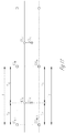
- FIG. 10 illustrates a timing diagram of relative temporal position of samples of incoming and outgoing audio streams, according to various embodiments of the present subject matter.
- FIG. 11 illustrates a timing diagram for calculation of outgoing fractional delay, according to various embodiments of the present subject matter. Details of the geometrical relation between incoming and outgoing samples are shown in FIG. 11 .
- Incoming fractional delay is calculated as an intermediate result by the incoming FD SRC as shown in FIG. 1 .
- FIG. 12 illustrates a block diagram of an FD SRC with direct computation of outgoing interpolator parameters, according to various embodiments of the present subject matter.
- Outgoing interpolator logic covers the scenario where zero or more than one sample was copied from the incoming input buffer to the history buffer of the incoming interpolator.
- the present subject matter can be applied for the case where sample rate of the outgoing audio stream is synchronized with external packet rate and interpolator parameters for the incoming audio sample are calculated from the interpolator parameters for the outgoing audio stream.
- Advantages of the present subject matter include preventing underflow or overflow of the outgoing audio buffer in bidirectional TDD systems by locking the number of incoming and outgoing samples, improved quality of synchronization of incoming and outgoing sample rates that is better than provided by two independent FD SRC modules, and the present subject matter consumes less MIPS and memory than two independent FD SRC modules.
- the wireless communications can include standard or nonstandard communications.
- standard wireless communications include link protocols including, but not limited to, BluetoothTM, IEEE 802.11 (wireless LANs), 802.15 (WPANs), 802.16 (WiMAX), cellular protocols including, but not limited to CDMA and GSM, ZigBee, and ultra-wideband (UWB) technologies.
- Such protocols support radio frequency communications and some support infrared communications.
- the present system is demonstrated as a radio system, it is possible that other forms of wireless communications can be used such as ultrasonic, optical, and others.
- the standards which can be used include past and present standards. It is also contemplated that future versions of these standards and new future standards may be employed without departing from the scope of the present subject matter.
- the wireless communications support a connection from other devices.
- Such connections include, but are not limited to, one or more mono or stereo connections or digital connections having link protocols including, but not limited to 802.3 (Ethernet), 802.4, 802.5, USB, ATM, Fibre-channel, Firewire or 1394, InfiniBand, or a native streaming interface.
- link protocols including, but not limited to 802.3 (Ethernet), 802.4, 802.5, USB, ATM, Fibre-channel, Firewire or 1394, InfiniBand, or a native streaming interface.
- link protocols including, but not limited to 802.3 (Ethernet), 802.4, 802.5, USB, ATM, Fibre-channel, Firewire or 1394, InfiniBand, or a native streaming interface.
- such connections include all past and present link protocols. It is also contemplated that future versions of these protocols and new future standards may be employed without departing from the scope of the present subject matter.
- Hearing assistance devices typically include an enclosure or housing, a microphone, hearing assistance device electronics including processing electronics, and a speaker or receiver.
- Processing electronics include a controller or processor, such as a digital signal processor (DSP), in various embodiments. Other types of processors may be used without departing from the scope of this disclosure.
- DSP digital signal processor
- the microphone is optional.
- the receiver is optional.
- Antenna configurations may vary and may be included within an enclosure for the electronics or be external to an enclosure for the electronics. Thus, the examples set forth herein are intended to be demonstrative and not a limiting or exhaustive depiction of variations.
- the hearing aids referenced in this patent application include a processor.
- the processor may be a digital signal processor (DSP), microprocessor, microcontroller, other digital logic, or combinations thereof.
- DSP digital signal processor
- the processing of signals referenced in this application can be performed using the processor. Processing may be done in the digital domain, the analog domain, or combinations thereof. Processing may be done using subband processing techniques. Processing may be done with frequency domain or time domain approaches. Some processing may involve both frequency and time domain aspects. For brevity, in some examples drawings may omit certain blocks that perform frequency synthesis, frequency analysis, analog-to-digital conversion, digital-to-analog conversion, amplification, and certain types of filtering and processing.
- the processor is adapted to perform instructions stored in memory which may or may not be explicitly shown.
- Various types of memory may be used, including volatile and nonvolatile forms of memory.
- instructions are performed by the processor to perform a number of signal processing tasks.
- analog components are in communication with the processor to perform signal tasks, such as microphone reception, or receiver sound embodiments (i.e., in applications where such transducers are used).
- signal tasks such as microphone reception, or receiver sound embodiments (i.e., in applications where such transducers are used).
- different realizations of the block diagrams, circuits, and processes set forth herein may occur without departing from the scope of the present subject matter.
- hearing assistance devices including but not limited to, cochlear implant type hearing devices, hearing aids, such as behind-the-ear (BTE), in-the-ear (ITE), in-the-canal (ITC), invisible-in-the-canal (IIC) or completely-in-the-canal (CIC) type hearing aids.
- BTE behind-the-ear
- ITE in-the-ear
- ITC in-the-canal
- IIC invisible-in-the-canal
- CIC completely-in-the-canal
- hearing assistance devices including but not limited to, cochlear implant type hearing devices, hearing aids, such as behind-the-ear (BTE), in-the-ear (ITE), in-the-canal (ITC), invisible-in-the-canal (IIC) or completely-in-the-canal (CIC) type hearing aids.
- BTE behind-the-ear
- ITE in-the-ear
- ITC in-the-canal
- IIC invisible-in-the-
- Such devices are also known as receiver-in-the-canal (RIC) or receiver-in-the-ear (RITE) hearing instruments. It is understood that other hearing assistance devices not expressly stated herein may fall within the scope of the present subject matter. Further, the present subject matter can be used for persons without hearing impairment that may be using wireless, or wired headphone and earbud devices for listening to audio streams.
- RIC receiver-in-the-canal
- RITE receiver-in-the-ear
Landscapes
- Engineering & Computer Science (AREA)
- Computer Networks & Wireless Communication (AREA)
- Signal Processing (AREA)
- Physics & Mathematics (AREA)
- Acoustics & Sound (AREA)
- Health & Medical Sciences (AREA)
- General Health & Medical Sciences (AREA)
- Neurosurgery (AREA)
- Otolaryngology (AREA)
- Multimedia (AREA)
- Synchronisation In Digital Transmission Systems (AREA)
Applications Claiming Priority (2)
| Application Number | Priority Date | Filing Date | Title |
|---|---|---|---|
| US201562211245P | 2015-08-28 | 2015-08-28 | |
| US201562211242P | 2015-08-28 | 2015-08-28 |
Publications (1)
| Publication Number | Publication Date |
|---|---|
| EP3139635A1 true EP3139635A1 (de) | 2017-03-08 |
Family
ID=57233274
Family Applications (1)
| Application Number | Title | Priority Date | Filing Date |
|---|---|---|---|
| EP16186053.1A Ceased EP3139635A1 (de) | 2015-08-28 | 2016-08-26 | Synchronisierung von audioströmen und abtastrate für drahtlose kommunikation |
Country Status (2)
| Country | Link |
|---|---|
| US (3) | US20170064651A1 (de) |
| EP (1) | EP3139635A1 (de) |
Families Citing this family (9)
| Publication number | Priority date | Publication date | Assignee | Title |
|---|---|---|---|---|
| GB2521607B (en) * | 2013-12-23 | 2016-03-23 | Nordic Semiconductor Asa | Integrated-Circuit Radio |
| EP3139635A1 (de) | 2015-08-28 | 2017-03-08 | Alex Volkov | Synchronisierung von audioströmen und abtastrate für drahtlose kommunikation |
| US20190114733A1 (en) * | 2017-10-12 | 2019-04-18 | Red Hat, Inc. | Display content currentness validation |
| WO2019088915A1 (en) | 2017-11-01 | 2019-05-09 | Razer (Asia-Pacific) Pte. Ltd. | Method and apparatus for resampling audio signal |
| DE102017011458B4 (de) * | 2017-12-12 | 2026-04-23 | WAGO Verwaltungsgesellschaft mit beschränkter Haftung | Teilnehmer eines Bussystems, Verfahren zum Betrieb und ein Bussystem |
| GB201912169D0 (en) * | 2019-08-23 | 2019-10-09 | Nordic Semiconductor Asa | Radio apparatus for communicating digital audio streams |
| EP4078996A1 (de) * | 2019-12-19 | 2022-10-26 | GN Hearing A/S | Reduzierung der taktverschiebung zwischen den taktsignalen eines ersten und eines zweiten hörgerätes |
| KR20230158841A (ko) * | 2022-05-12 | 2023-11-21 | 현대자동차주식회사 | 차량 제어 시스템 및 방법 |
| KR20240025226A (ko) | 2022-08-18 | 2024-02-27 | 삼성전자주식회사 | 시스템 온 칩, 및 그것을 갖는 데이터 처리 시스템 및 그것의 동작 방법 |
Citations (7)
| Publication number | Priority date | Publication date | Assignee | Title |
|---|---|---|---|---|
| US7339503B1 (en) * | 2006-09-29 | 2008-03-04 | Silicon Laboratories Inc. | Adaptive asynchronous sample rate conversion |
| US7414550B1 (en) * | 2006-06-30 | 2008-08-19 | Nvidia Corporation | Methods and systems for sample rate conversion and sample clock synchronization |
| EP2355387A1 (de) * | 2010-01-27 | 2011-08-10 | Harman Becker Automotive Systems GmbH | Abtastratenwandler für codierte Datenströme |
| US8405532B1 (en) * | 2009-05-28 | 2013-03-26 | Audience, Inc. | Asynchronous sample rate converter |
| US20130243203A1 (en) * | 2007-09-19 | 2013-09-19 | Fraunhofer-Gesellschaft Zur Foerderung Der Angewandten Forschung E.V. | Device and a method for determining a component signal with high accuracy |
| EP2736274A2 (de) * | 2012-11-21 | 2014-05-28 | Starkey Laboratories, Inc. | Verfahren und Vorrichtung zur Synchronisierung von Hörgeräten über drahtlose Kommunikation |
| EP2897384A2 (de) * | 2014-01-15 | 2015-07-22 | Jeffrey Paul Solum | Verfahren und Vorrichtung zur Audiowiedergabe in drahtlosen Hörgeräten |
Family Cites Families (15)
| Publication number | Priority date | Publication date | Assignee | Title |
|---|---|---|---|---|
| US5666428A (en) | 1991-01-09 | 1997-09-09 | Elan Home Systems, L.L.C. | Audio distribution system |
| JP2628126B2 (ja) | 1992-03-09 | 1997-07-09 | 日立電子株式会社 | 無線機およびその音声伝送方法 |
| US5646446A (en) | 1995-12-22 | 1997-07-08 | Fairchild Space And Defense Corporation | Three-dimensional flexible assembly of integrated circuits |
| US20050099341A1 (en) | 2003-11-12 | 2005-05-12 | Gennum Corporation | Antenna for a wireless hearing aid system |
| US7492828B2 (en) | 2004-06-18 | 2009-02-17 | Qualcomm Incorporated | Time synchronization using spectral estimation in a communication system |
| JP2008505515A (ja) | 2004-06-29 | 2008-02-21 | コーニンクレッカ フィリップス エレクトロニクス エヌ ヴィ | ジッタが無いサンプリングレート変換 |
| DE102005046169A1 (de) | 2005-09-27 | 2007-04-05 | Siemens Audiologische Technik Gmbh | Hörhilfegerät mit einer Antenne |
| US7715578B2 (en) | 2005-11-30 | 2010-05-11 | Research In Motion Limited | Hearing aid having improved RF immunity to RF electromagnetic interference produced from a wireless communications device |
| DK2207366T3 (en) | 2009-01-12 | 2014-12-01 | Starkey Lab Inc | SYSTEM FOR DETERMINING THE LEVEL OF SOUND PRESSURE AT eardrum OF USE OF MEASUREMENTS AWAY from the eardrum |
| US10362381B2 (en) | 2011-06-01 | 2019-07-23 | Staton Techiya, Llc | Methods and devices for radio frequency (RF) mitigation proximate the ear |
| US10743116B2 (en) | 2013-04-30 | 2020-08-11 | Starkey Laboratories, Inc. | Small loop antenna with shorting conductors for hearing assistance devices |
| JP6232870B2 (ja) | 2013-09-11 | 2017-11-22 | 株式会社リコー | 無線通信システム、無線通信方法、プログラム、及び記録媒体 |
| GB2521149B (en) | 2013-12-10 | 2021-08-18 | Grass Valley Ltd | Adjusting occupancies of a set of buffers |
| EP2928210A1 (de) | 2014-04-03 | 2015-10-07 | Oticon A/s | Binaurales Hörgerätesystem mit binauraler Rauschunterdrückung |
| EP3139635A1 (de) | 2015-08-28 | 2017-03-08 | Alex Volkov | Synchronisierung von audioströmen und abtastrate für drahtlose kommunikation |
-
2016
- 2016-08-26 EP EP16186053.1A patent/EP3139635A1/de not_active Ceased
- 2016-08-26 US US15/248,287 patent/US20170064651A1/en not_active Abandoned
-
2021
- 2021-07-23 US US17/443,310 patent/US11910337B2/en active Active
-
2024
- 2024-01-23 US US18/419,738 patent/US12328692B2/en active Active
Patent Citations (7)
| Publication number | Priority date | Publication date | Assignee | Title |
|---|---|---|---|---|
| US7414550B1 (en) * | 2006-06-30 | 2008-08-19 | Nvidia Corporation | Methods and systems for sample rate conversion and sample clock synchronization |
| US7339503B1 (en) * | 2006-09-29 | 2008-03-04 | Silicon Laboratories Inc. | Adaptive asynchronous sample rate conversion |
| US20130243203A1 (en) * | 2007-09-19 | 2013-09-19 | Fraunhofer-Gesellschaft Zur Foerderung Der Angewandten Forschung E.V. | Device and a method for determining a component signal with high accuracy |
| US8405532B1 (en) * | 2009-05-28 | 2013-03-26 | Audience, Inc. | Asynchronous sample rate converter |
| EP2355387A1 (de) * | 2010-01-27 | 2011-08-10 | Harman Becker Automotive Systems GmbH | Abtastratenwandler für codierte Datenströme |
| EP2736274A2 (de) * | 2012-11-21 | 2014-05-28 | Starkey Laboratories, Inc. | Verfahren und Vorrichtung zur Synchronisierung von Hörgeräten über drahtlose Kommunikation |
| EP2897384A2 (de) * | 2014-01-15 | 2015-07-22 | Jeffrey Paul Solum | Verfahren und Vorrichtung zur Audiowiedergabe in drahtlosen Hörgeräten |
Non-Patent Citations (3)
| Title |
|---|
| AKESTER R ET AL: "A new audio skew detection and correction algorithm", PROCEEDINGS / 2002 IEEE INTERNATIONAL CONFERENCE ON MULTIMEDIA AND EXPO : AUGUST 26 - 29, 2002, SWISS FEDERAL INSTITUTE OF TECHNOLOGY, LAUSANNE, SWITZERLAND, IEEE OPERATIONS CENTER, PISCATAWAY, NJ, vol. 2, 26 August 2002 (2002-08-26), pages 261, XP032964458, ISBN: 978-0-7803-7304-4, DOI: 10.1109/ICME.2002.1035569 * |
| KLEIDER JOHN ET AL: "On the Performance of Variable Fractional Delay Arbitrary Sample Rate Conversion for Digital Signals", 2014 IEEE MILITARY COMMUNICATIONS CONFERENCE, IEEE, 6 October 2014 (2014-10-06), pages 724 - 730, XP032686391, DOI: 10.1109/MILCOM.2014.126 * |
| MAREK BLOK: "Fractional delay filter design for sample rate conversion", COMPUTER SCIENCE AND INFORMATION SYSTEMS (FEDCSIS), 2012 FEDERATED CONFERENCE ON, IEEE, 9 September 2012 (2012-09-09), pages 701 - 706, XP032267195, ISBN: 978-1-4673-0708-6 * |
Also Published As
| Publication number | Publication date |
|---|---|
| US20240244544A1 (en) | 2024-07-18 |
| US12328692B2 (en) | 2025-06-10 |
| US20210410090A1 (en) | 2021-12-30 |
| US20170064651A1 (en) | 2017-03-02 |
| US11910337B2 (en) | 2024-02-20 |
Similar Documents
| Publication | Publication Date | Title |
|---|---|---|
| US12328692B2 (en) | Synchronization of audio streams and sampling rate for wireless communication | |
| DK2897384T3 (en) | Method and device for audio reproduction in wireless hearing aids | |
| US10674465B2 (en) | Method and apparatus for synchronizing hearing instruments via wireless communication | |
| US8532241B2 (en) | Time synchronization apparatus based on parallel processing | |
| DK3116239T3 (en) | PROCEDURE FOR CHOOSING THE TRANSFER DIRECTION IN A BINAURAL HEARING | |
| EP2341744B1 (de) | Schema mit geringem Flimmern zur durchgehenden Latenzzeitsteuerung für isochrone Kommunikationen auf Grundlage von Senderzeitstempelinformationen | |
| US8340333B2 (en) | Hearing aid noise reduction method, system, and apparatus | |
| US10178281B2 (en) | System and method for synchronizing audio and video signals for a listening system | |
| US20230007411A1 (en) | Audio synchronization for hearing devices | |
| CN107113283A (zh) | 在低延迟多媒体流式传输环境中处理有问题的模式的方法 | |
| Kiselev et al. | WHISPER: Wirelessly synchronized distributed audio sensor platform | |
| CN114270735B (zh) | 用于传送数字音频流的无线电设备 | |
| US20200137502A1 (en) | Rate matching algorithm and independent device synchronization | |
| US12063475B2 (en) | Reducing clock skew between clock signals of first and second hearing devices | |
| EP4402809A2 (de) | Taktsynchronisierung einer drahtlosen vorrichtung | |
| US12439352B1 (en) | Systems and methods for audio timing and synchronization | |
| WO2020206465A1 (en) | Software based audio timing and synchronization |
Legal Events
| Date | Code | Title | Description |
|---|---|---|---|
| PUAI | Public reference made under article 153(3) epc to a published international application that has entered the european phase |
Free format text: ORIGINAL CODE: 0009012 |
|
| 17P | Request for examination filed |
Effective date: 20160826 |
|
| AK | Designated contracting states |
Kind code of ref document: A1 Designated state(s): AL AT BE BG CH CY CZ DE DK EE ES FI FR GB GR HR HU IE IS IT LI LT LU LV MC MK MT NL NO PL PT RO RS SE SI SK SM TR |
|
| AX | Request for extension of the european patent |
Extension state: BA ME |
|
| RAP1 | Party data changed (applicant data changed or rights of an application transferred) |
Owner name: STARKEY LABORATORIES, INC. |
|
| RIN1 | Information on inventor provided before grant (corrected) |
Inventor name: MOVAHEDI, MOHAMMAD REZA Inventor name: BOGHRATI, BAKTASH Inventor name: SOLUM, JEFFREY PAUL Inventor name: VOLKOV, ALEX Inventor name: CUNNINGHAM, EDWARD JOHN |
|
| 17Q | First examination report despatched |
Effective date: 20180621 |
|
| STAA | Information on the status of an ep patent application or granted ep patent |
Free format text: STATUS: THE APPLICATION HAS BEEN REFUSED |
|
| 18R | Application refused |
Effective date: 20200825 |