EP3139636B1 - Hörgerät mit einem auf signalenergieverschiebung basierenden rückkopplungsunterdrückungssystem - Google Patents
Hörgerät mit einem auf signalenergieverschiebung basierenden rückkopplungsunterdrückungssystem Download PDFInfo
- Publication number
- EP3139636B1 EP3139636B1 EP16186507.6A EP16186507A EP3139636B1 EP 3139636 B1 EP3139636 B1 EP 3139636B1 EP 16186507 A EP16186507 A EP 16186507A EP 3139636 B1 EP3139636 B1 EP 3139636B1
- Authority
- EP
- European Patent Office
- Prior art keywords
- gain
- signal
- time
- feedback
- time period
- Prior art date
- Legal status (The legal status is an assumption and is not a legal conclusion. Google has not performed a legal analysis and makes no representation as to the accuracy of the status listed.)
- Active
Links
Images



Classifications
-
- H—ELECTRICITY
- H04—ELECTRIC COMMUNICATION TECHNIQUE
- H04R—LOUDSPEAKERS, MICROPHONES, GRAMOPHONE PICK-UPS OR LIKE ACOUSTIC ELECTROMECHANICAL TRANSDUCERS; ELECTRIC HEARING AIDS; PUBLIC ADDRESS SYSTEMS
- H04R25/00—Electric hearing aids
-
- H—ELECTRICITY
- H04—ELECTRIC COMMUNICATION TECHNIQUE
- H04R—LOUDSPEAKERS, MICROPHONES, GRAMOPHONE PICK-UPS OR LIKE ACOUSTIC ELECTROMECHANICAL TRANSDUCERS; ELECTRIC HEARING AIDS; PUBLIC ADDRESS SYSTEMS
- H04R25/00—Electric hearing aids
- H04R25/45—Prevention of acoustic reaction, i.e. acoustic oscillatory feedback
- H04R25/453—Prevention of acoustic reaction, i.e. acoustic oscillatory feedback electronically
-
- H—ELECTRICITY
- H04—ELECTRIC COMMUNICATION TECHNIQUE
- H04R—LOUDSPEAKERS, MICROPHONES, GRAMOPHONE PICK-UPS OR LIKE ACOUSTIC ELECTROMECHANICAL TRANSDUCERS; ELECTRIC HEARING AIDS; PUBLIC ADDRESS SYSTEMS
- H04R25/00—Electric hearing aids
- H04R25/35—Electric hearing aids using translation techniques
- H04R25/356—Amplitude, e.g. amplitude shift or compression
-
- H—ELECTRICITY
- H04—ELECTRIC COMMUNICATION TECHNIQUE
- H04R—LOUDSPEAKERS, MICROPHONES, GRAMOPHONE PICK-UPS OR LIKE ACOUSTIC ELECTROMECHANICAL TRANSDUCERS; ELECTRIC HEARING AIDS; PUBLIC ADDRESS SYSTEMS
- H04R1/00—Details of transducers, loudspeakers or microphones
- H04R1/10—Earpieces; Attachments therefor ; Earphones; Monophonic headphones
- H04R1/1041—Mechanical or electronic switches, or control elements
-
- H—ELECTRICITY
- H04—ELECTRIC COMMUNICATION TECHNIQUE
- H04R—LOUDSPEAKERS, MICROPHONES, GRAMOPHONE PICK-UPS OR LIKE ACOUSTIC ELECTROMECHANICAL TRANSDUCERS; ELECTRIC HEARING AIDS; PUBLIC ADDRESS SYSTEMS
- H04R2225/00—Details of deaf aids covered by H04R25/00, not provided for in any of its subgroups
- H04R2225/43—Signal processing in hearing aids to enhance the speech intelligibility
Definitions
- the present application relates to audio processing in hearing devices, e.g. hearing aids.
- the disclosure relates specifically to the topic of acoustic or mechanical feedback from an output to an input transducer and in particular to the reduction or elimination of such feedback.
- the disclosure relates to a hearing device.
- the application furthermore relates to a method of operating a hearing device and to the use of a hearing device.
- the application further relates to a data processing system comprising a processor and program code means for causing the processor to perform at least some of the steps of the method.
- Embodiments of the disclosure may e.g. be useful in applications such as hearing aids, headsets, ear phones, active ear protection systems, handsfree telephone systems, mobile telephones, teleconferencing systems, public address systems, karaoke systems, classroom amplification systems, etc.
- the present disclosure relates to the well-known acoustic feedback problem in audio systems comprising a forward path for amplifying an input sound from the environment picked up by an acoustic input transducer and an output transducer for presenting an amplified version of the input signal as an output sound to the environment, e.g. to one or more users.
- Acoustic feedback occurs because the output transducer (e.g. loudspeaker) signal from an audio system providing amplification of a signal picked up by an input transducer (e-.g a microphone) is partly returned to the microphone via an acoustic coupling through the air or other media. The part of the loudspeaker signal returned to the microphone is then re-amplified by the system before it is re-presented at the loudspeaker, and again returned to the microphone. As this cycle continues, the effect of acoustic feedback becomes audible as artifacts or even worse, howling, when the system becomes unstable. The problem appears typically when the microphone and the loudspeaker are placed closely together, as e.g. in hearing aids or other audio systems.
- the output transducer e.g. loudspeaker
- Feedback cancellation is typically provided by subtracting an estimate of the feedback signal from the input signal to provide a feedback corrected input signal.
- Adaptive feedback estimation has the ability to track feedback path changes over time. It is based on a linear time invariant filter to estimate the feedback path but its filter weights are updated over time.
- the filter update may be calculated using stochastic gradient algorithms, e.g. including some form of the Least Mean Square (LMS) or the Normalized LMS (NLMS) algorithms. They both have the property to minimize an error signal (e.g.
- LMS Least Mean Square
- NLMS Normalized LMS
- the NLMS additionally normalizing the filter update with respect to the squared Euclidean norm of some reference signal (e.g. the output signal).
- some reference signal e.g. the output signal.
- EP2148527A1 deals with a hearing aid system comprising left and right hearing aid devices for completely eliminating the acoustic feedback by using inter-aural signal transmission (cross-over of respective microphone signals to the opposite device) and application of binary (complementary) gain patterns in the respective hearing aid devices.
- US2015011266A1 deals with a speakerphone for use in a teleconference setup wherein a complementary filtering scheme is applied in the microphone and loudspeaker paths, respectively.
- This present disclosure provides a stand-alone solution to deal with the acoustic feedback problem, but it can also be used in combination with other known feedback control systems, e.g. a feedback cancellation system comprising an adaptive filter for estimating a current external feedback path.
- An object of the present application is provide an alternative scheme for reducing or eliminating external feedback in a hearing device.
- a hearing device :
- an object of the application is achieved by a hearing device, e.g. a hearing aid, comprising an input transducer for converting an input sound to an electric input signal representing sound, an output transducer for converting a processed electric output signal to an output sound or mechanical vibration, and a signal processing unit operationally coupled to the input and output transducers and configured to apply a requested forward gain to the electric input signal or a signal originating therefrom, the input transducer, the signal processing unit and the output transducer forming part of a forward path of the hearing device.
- the forward path applies a resulting forward gain to the electric input signal and provides a resulting signal.
- the hearing device further comprises a feedback reduction unit for reducing a risk of howl due to acoustic or mechanical feedback of an external feedback path from the output transducer to the input transducer.
- the forward path and the external feedback path defines a loop path exhibiting a roundtrip loop delay.
- the feedback reduction unit is configured to modulate the requested forward gain in time to provide that the resulting forward gain exhibits a first, increased gain A H in a first time period T H and a second, reduced gain A L in a second time period T L , wherein at least one of the first gain A H , the second gain A L , the first time period T H , and the second time period T L is/are determined according to a predetermined or adaptively determined criterion.
- the terms 'the first, increased gain A H ' and 'the second, reduced gain A L ' are intended to mean increased and reduced, respectively, relative to the requested gain (at a given point in time (in a time-domain representation) or at a given point in time and frequency (in a time-frequency representation)).
- the term 'the requested gain' is in the present context taken to mean the gain that is to be applied to the electric input signal to provide an intended amplification of the electric input signal (e.g. to compensate for a user's hearing impairment and/or to compensate for a noisy environment, etc.).
- the feedback reduction unit is configured to modulate the requested frequency dependent forward gain in time, to provide that the resulting forward gain is higher than the requested gain in some periods of time and lower than the requested gain in other periods of time.
- the modulation of the requested forward gain provided by the feedback reduction unit exhibits a predetermined gain pattern over time with predefined and/or adaptively determined and adjusted gains A 1 , A 2 , A 3 , ..., A N in corresponding time periods T 1 , T 2 , T 3 , ..., T N .
- the applied gain pattern comprises repeated occurrence of the predefined gain pattern A 1 , A 2 , A 3 , ..., A N , wherein the repetition time (or cycle time) is T 1 + T 2 + T 3 + ... + T N .
- N is larger than or equal to two. In an embodiment, N is equal to 2 such as equal to 3.
- the first and second time periods are subdivided into a number of sub time periods T H1 , T H2 , ..., T HNH and T L1 , T L2 , ..., T LNL , respectively, where NH and NL are the number of sub time periods of T H and T L , respectively, and wherein each time period has its corresponding (possibly different) relatively high (A H1 , A H2 , ..., A HNH ) and relatively low (A L1 , A L2 , ..., A LNL ) gain, respectively.
- the applied gain pattern comprises repeated occurrence of the predefined gain pattern (A H1 , A H2 , ..., A HNH , A L1 , A L2 , ..., A LNL ), wherein the repetition time (or cycle time) is T H1 + T H2 + ... + T HNH + T L1 + T L2 + ...+ T LNL .
- the predetermined (or dynamically determined) criterion comprises that the first T H and/or the second T L time period is determined in dependence of a, possibly averaged, roundtrip loop delay of the forward path and the external feedback path.
- the first and second time periods are determined in dependence of the round trip loop delay (or an averaged round trip loop delay).
- the modulation is periodic.
- the first and second time periods succeed each other (a second time period follows a first time period, and a first time period follows a second time period).
- the first and second time periods are repeated (with or without a pause between them).
- the first and second time periods are repeated and follow immediately after one another (without a pause between them: T H , T L , T H , T L , .).
- the gain modulation is applied only in a specific feedback cancellation mode of operation.
- there is a fading between the first and second time periods e.g. as shown in FIG. 2B .
- the second time period T L is selected either similar to or smaller than the loop delay or an averaged round trip loop delay T loop or selected in relation to the loop delay by T loop /2 ⁇ T L ⁇ T loop *2. In an embodiment, the second time period T L is selected in relation to the loop delay or an averaged round trip loop delay by T loop /10 ⁇ T L ⁇ T loop * 10. In an embodiment, the second time period T L is larger than or equal to the loop delay or an averaged round trip loop delay T loop . In an embodiment, the first time period, T H , is selected either (essentially) equal to the loop delay (or an averaged round trip loop delay), T loop , or selected in relation to the loop delay by e.g. T loop /2 ⁇ T H ⁇ T loop *2 or T loop /10 ⁇ T H ⁇ T loop * 10.
- the loop delay may be different at different points in time, e.g. depending on the currently applied algorithms in the signal processing unit.
- the hearing device comprises a control unit for estimating a current loop or average loop delay or a deviation from a typical loop delay or a typical average loop delay.
- the control unit is configured to measure a loop delay comprising a sum of a delay of the forward path and a delay of the feedback path.
- a predefined test-signal (or a recognizable (preferably inaudible) modulation, e.g. dip or peak) is inserted in the forward path by the control unit and its round trip travel time measured (or estimated), e.g. by identification of the test signal (or modulation) when it arrives in the forward path after a single (or a number of) propagation of the loop.
- a typical loop delay is of the order of ms, e.g. around 10 ms.
- the acoustic part of the loop delay is much less than the electric (processing) part of the loop delay.
- the electric (processing) part of the loop delay is in the range between 2 ms and 10 ms, e.g. in the range between 5 ms and 8 ms, e.g. around 7 ms.
- the loop delay may be relatively constant over time (and e.g. determined in advance of operation of the hearing device) or be different at different points in time, e.g. depending on the currently applied algorithms in the signal processing unit (e.g. dynamically determined (estimated) during use).
- the hearing device (HD) may e.g. comprise a memory unit wherein typical loop delays in different modes of operation of the hearing device are stored.
- the predetermined or adaptively determined criterion comprises that the first and second time periods and the first and second gains are configured to conserve energy in the resulting signal compared to the signal before said modulation of the requested forward gain.
- the first and second time periods and the first and second gains are configured to conserve energy in the resulting signal compared to the signal before said modulation of said requested forward gain.
- the applied gain pattern comprising repeated occurrences of the predefined gain pattern A 1 , A 2 , A 3 , ..., A N (wherein the repetition time (or cycle time) is T 1 + T 2 + T 3 + ... +T N ), is configured to conserve energy in the resulting signal compared to the signal before the modulation of the requested forward gain.
- the first and second time periods T H , T L , and the reduced gain A L are determined first and the increased gain A H is subsequently determined to conserve energy in the resulting signal (compared to a situation without application of the increased and reduced gains according to the present disclosure).
- the first, increased gain A H is determined from the second, reduced gain A L , the first and second time periods T H , and T L .
- a H f(A L , T H , T L .) under the constraint that energy is conserved in the resulting signal (compared to the signal before the gain modification).
- the first, increased gain A H is equal to SQRT(2), and the second, reduced gain A L is equal to 0.
- the first and second time periods T H and T L are substantially equal.
- T H f(A L , A H , T L ).
- T L f(A L , A H , T H ).
- the relations are fulfilled under the further constraint that energy is conserved in the resulting signal.
- the predetermined or adaptively determined criterion comprises that the first time period T H and the second time period T L are chosen randomly, whereas the first, increased gain A H and the second, reduced gain A L are chosen to conserve the output signal energy.
- the hearing device is configured to provide that the increased gain A H and/or the reduced gain A L is/are variable during said first and second time periods T H , and T L .
- the hearing device is configured to provide that the increased gain A H is (e.g. monotonously) increasing from a minimum value (e.g. A H0 ) towards a maximum value (e.g. A H1 ) (e.g. in a first half-period of the first time period T H ) and then (e.g. monotonously) decreasing towards the minimum value (e.g. during a second half-period of the first time period T H ).
- the hearing device is configured to provide that the reduced gain A L is (e.g.
- the hearing device is configured to provide that the increased gain A H and/or the reduced gain A L is/are (essentially) constant during said first and second time periods T H and T L , respectively.
- the hearing device comprises a time to time-frequency conversion unit for providing the electric input signal or a signal derived therefrom in a number of frequency bands.
- the time to time-frequency conversion unit comprises an analysis filter bank or a Fourier transformation unit (e.g. based on a Fast Fourier transformation algorithm).
- the hearing device comprises time-frequency to time conversion unit for providing an electric output signal as a time domain signal (e.g a synthesis filter bank or an inverse Fast Fourier transformation algorithm).
- the hearing device is configured to provide that the gain modification over time is performed in one or more selected or all frequency bands.
- each selected band may exhibit individual gain modulation characteristics (e.g. individual (band specific) A H , A L , T H , T L ). These four (or more, e.g. A 3 , A 4 , ..., T 3 , T 4 , ...) parameters for each band can be set up independent of other bands.
- the gain modulation algorithm does not have to be enabled at all times, but can be enabled/disabled in each frequency band separately, e.g. online, e.g. based on one or more detectors for monitoring a current input signal of the hearing device and/or on the current acoustic environment (e.g. including a feedback detector).
- the hearing device is adapted to provide that the increased gain A H and/or the reduced gain A L is/are configurable for at least some of the frequency bands.
- the increased gain A H and/or the reduced gain A L are set to the same values A H,0 and A L,0 , respectively, in at least some of the frequency bands.
- each of A H (FB i ), A L (FB i ), T H (FB i ), T L (FB i ) and a time offset T d (FB i ) between a gain pattern of a neighbouring frequency band can be chosen independent of each other.
- the hearing device is adapted to provide that said increased gain A H said reduced gain A L are only applied in frequency bands expected to be at risk of howl.
- hearing device is adapted to provide that said increased gain A H said reduced gain A L are only applied in frequency bands expected to be at risk of howl.
- the frequency band or bands expected to be at risk of howl may e.g. be estimated or determined in advance of normal operation of the hearing device, e.g. at a fitting session, where the hearing device is adapted to a particular users needs (e.g. the a hearing e.g. to compensate for a hearing impairment of the user).
- frequency band or bands expected to be at risk of howl may e.g. be selected automatically online, e.g. determined by a feedback detector for estimating a current level of feedback in a given frequency band.
- the hearing device is adapted to provide that said increased gain A H said reduced gain A L are only applied in frequency bands above a first threshold frequency, f THL (cf. e.g. FIG. 3A ).
- the first threshold frequency, f THL is smaller than or equal to 1 kHz.
- the first threshold frequency, f THL is in a range between 500 Hz and 1 kHz.
- the first threshold frequency, f THL is smaller than or equal to 2 kHz.
- the first threshold frequency, f THL is in a range between 1 kHz and 2 kHz.
- the hearing device is adapted to provide that the increased gain A H and the reduced gain A L are only applied in frequency bands above a first threshold frequency, f THL and below a second threshold frequency, f THH .
- the second threshold frequency, f THH is larger than or equal to 5 kHz.
- the second threshold frequency, f THL is in a range between 5 kHz and 10 kHz.
- the hearing device comprises a hearing aid, a headset, an active ear protection system or a combination thereof.
- the signal processing unit is configured for enhancing the input signals and providing a processed output signal.
- the hearing device e.g. the signal processing unit
- the hearing device is adapted to provide a frequency dependent gain and/or a level dependent compression and/or a transposition (with or without frequency compression) of one or more frequency ranges to one or more other frequency ranges, e.g. to compensate for a hearing impairment of a user.
- a frequency dependent gain and/or a level dependent compression and/or a transposition with or without frequency compression
- the hearing device comprises an output transducer adapted for providing a stimulus perceived by the user as an acoustic signal based on a processed electric signal.
- the output transducer comprises a receiver (loudspeaker) for providing the stimulus as an acoustic signal to the user.
- the output transducer comprises a vibrator for providing the stimulus as mechanical vibration of a skull bone to the user (e.g. in a bone-attached or bone-anchored hearing device).
- the hearing device comprises an input transducer for providing an electric input signal representing sound.
- the hearing device comprises a directional microphone system adapted to enhance a target acoustic source among a multitude of acoustic sources in the local environment of the user wearing the hearing device.
- the directional system is adapted to detect (such as adaptively detect) from which direction a particular part of the microphone signal originates. This can be achieved in various different ways as e.g. described in the prior art.
- the hearing device comprises antenna and transceiver circuitry for wirelessly receiving a direct electric input signal from another device, e.g. a communication device or another hearing device.
- the hearing device is (or comprises) a portable device, e.g. a device comprising a local energy source, e.g. a battery, e.g. a rechargeable battery.
- a portable device e.g. a device comprising a local energy source, e.g. a battery, e.g. a rechargeable battery.
- the hearing device comprises a forward or signal path between an input transducer (microphone system and/or direct electric input (e.g. a wireless receiver)) and an output transducer.
- the signal processing unit is located in the forward path.
- the hearing device comprises an analysis path comprising functional components for analyzing the input signal (e.g. determining a level, a modulation, a type of signal, an acoustic feedback estimate, etc.).
- some or all signal processing of the analysis path and/or the signal path is conducted in the frequency domain.
- some or all signal processing of the analysis path and/or the signal path is conducted in the time domain.
- an analogue electric signal representing an acoustic signal is converted to a digital audio signal in an analogue-to-digital (AD) conversion process, where the analogue signal is sampled with a predefined sampling frequency or rate f s , f s being e.g. in the range from 8 kHz to 40 kHz (adapted to the particular needs of the application) to provide digital samples x n (or x[n]) at discrete points in time t n (or n), each audio sample representing the value of the acoustic signal at t n by a predefined number N s of bits, N s being e.g. in the range from 1 to 16 bits.
- AD analogue-to-digital
- a number of audio samples are arranged in a time frame.
- a time frame comprises 64 audio data samples. Other frame lengths may be used depending on the practical application.
- the hearing devices comprise an analogue-to-digital (AD) converter to digitize an analogue input with a predefined sampling rate, e.g. 20 kHz.
- the hearing devices comprise a digital-to-analogue (DA) converter to convert a digital signal to an analogue output signal, e.g. for being presented to a user via an output transducer.
- AD analogue-to-digital
- DA digital-to-analogue
- the hearing device e.g. the microphone unit, and or the transceiver unit comprise(s) a TF-conversion unit for providing a time-frequency representation of an input signal.
- the time-frequency representation comprises an array or map of corresponding complex or real values of the signal in question in a particular time and frequency range.
- the TF conversion unit comprises a filter bank for filtering a (time varying) input signal and providing a number of (time varying) output signals each comprising a distinct frequency range of the input signal.
- the TF conversion unit comprises a Fourier transformation unit for converting a time variant input signal to a (time variant) signal in the frequency domain.
- the frequency range considered by the hearing device from a minimum frequency f min to a maximum frequency f max comprises a part of the typical human audible frequency range from 20 Hz to 20 kHz, e.g. a part of the range from 20 Hz to 12 kHz.
- a signal of the forward and/or analysis path of the hearing device is split into a number NI of frequency bands, where NI is e.g. larger than 5, such as larger than 10, such as larger than 50, such as larger than 100, such as larger than 500, at least some of which are processed individually.
- the hearing device is/are adapted to process a signal of the forward and/or analysis path in a number NP of different frequency channels ( NP ⁇ NI ).
- the frequency channels may be uniform or non-uniform in width (e.g. increasing in width with frequency), overlapping or non-overlapping.
- the hearing device comprises a level detector (LD) for determining the level of an input signal (e.g. on a band level and/or of the full (wide band) signal).
- the input level of the electric microphone signal picked up from the user's acoustic environment is e.g. a classifier of the environment.
- the level detector is adapted to classify a current acoustic environment of the user according to a number of different (e.g. average) signal levels, e.g. as a HIGH-LEVEL or LOW-LEVEL environment.
- the hearing device comprises a voice detector (VD) for determining whether or not an input signal comprises a voice signal (at a given point in feedback reduction unit time).
- a voice signal is in the present context taken to include a speech signal from a human being. It may also include other forms of utterances generated by the human speech system (e.g. singing).
- the voice detector unit is adapted to classify a current acoustic environment of the user as a VOICE or NO-VOICE environment. This has the advantage that time segments of the electric microphone signal comprising human utterances (e.g. speech) in the user's environment can be identified, and thus separated from time segments only comprising other sound sources (e.g. artificially generated noise).
- the voice detector is adapted to detect as a VOICE also the user's own voice. Alternatively, the voice detector is adapted to exclude a user's own voice from the detection of a VOICE.
- the hearing device comprises an own voice detector for detecting whether a given input sound (e.g. a voice) originates from the voice of the user of the system.
- a given input sound e.g. a voice
- the microphone system of the hearing device is adapted to be able to differentiate between a user's own voice and another person's voice and possibly from NON-voice sounds.
- the hearing device comprises an acoustic (and/or mechanical) feedback suppression system (in addition to the feedback reduction unit).
- the hearing device further comprises other relevant functionality for the application in question, e.g. compression, noise reduction, etc.
- the hearing device comprises a listening device, e.g. a hearing aid, e.g. a hearing instrument, e.g. a hearing instrument adapted for being located at the ear or fully or partially in the ear canal of a user, e.g. a headset, an earphone, an ear protection device or a combination thereof.
- a listening device e.g. a hearing aid, e.g. a hearing instrument, e.g. a hearing instrument adapted for being located at the ear or fully or partially in the ear canal of a user, e.g. a headset, an earphone, an ear protection device or a combination thereof.
- a hearing device as described above, in the 'detailed description of embodiments' and in the claims, is moreover provided.
- use is provided in a system comprising audio distribution, e.g. a system comprising a microphone and a loudspeaker in sufficiently close proximity of each other to cause feedback from the loudspeaker to the microphone during operation by a user.
- use is provided in a system comprising one or more hearing instruments, headsets, ear phones, active ear protection systems, etc., e.g. in handsfree telephone systems, teleconferencing systems, public address systems, karaoke systems, classroom amplification systems, etc.
- a method of operating a hearing device comprising a forward path for applying a resulting forward gain to the electric input signal and providing a resulting signal.
- the method comprises
- the method further comprises
- the method comprises
- the method comprises
- the method comprises providing that at least one (such as at least two, or all) of said first, increased gain A H , said first time period T H , said second, reduced gain A L , and said second time period T L , is/are selected using a model of human auditory perception in order to make said modulation of the requested forward gain less audible or even inaudible to the user.
- the model of human auditory perception comprises a psychoacoustic model.
- At least one of said first, increased gain A H , said first time period T H , said second, reduced gain A L , and said second time period T L is/are selected based on knowledge of one or more of a user's hearing loss, auditory bandwidth, spectro/temporal masking effect and/or modulation sensitivity, in order to make the sound processing less audible or even inaudible to the user.
- a computer readable medium :
- a tangible computer-readable medium storing a computer program comprising program code means for causing a data processing system to perform at least some (such as a majority or all) of the steps of the method described above, in the 'detailed description of embodiments' and in the claims, when said computer program is executed on the data processing system is furthermore provided by the present application.
- Such computer-readable media can comprise RAM, ROM, EEPROM, CD-ROM or other optical disk storage, magnetic disk storage or other magnetic storage devices, or any other medium that can be used to carry or store desired program code in the form of instructions or data structures and that can be accessed by a computer.
- Disk and disc includes compact disc (CD), laser disc, optical disc, digital versatile disc (DVD), floppy disk and Blu-ray disc where disks usually reproduce data magnetically, while discs reproduce data optically with lasers. Combinations of the above should also be included within the scope of computer-readable media.
- the computer program can also be transmitted via a transmission medium such as a wired or wireless link or a network, e.g. the Internet, and loaded into a data processing system for being executed at a location different from that of the tangible medium.
- a transmission medium such as a wired or wireless link or a network, e.g. the Internet
- the proposed method may be implemented/stored in RAM, ROM, EEPROM or other computer readable media of the hearing device.
- a data processing system :
- a data processing system comprising a processor and program code means for causing the processor to perform at least some (such as a majority or all) of the steps of the method described above, in the 'detailed description of embodiments' and in the claims is furthermore provided by the present application.
- a hearing system :
- a hearing system comprising a hearing device as described above, in the 'detailed description of embodiments', and in the claims, AND an auxiliary device is moreover provided.
- the system is adapted to establish a communication link between the hearing device and the auxiliary device to provide that information (e.g. control and status signals, possibly audio signals) can be exchanged or forwarded from one to the other.
- information e.g. control and status signals, possibly audio signals
- the auxiliary device is or comprises an audio gateway device adapted for receiving a multitude of audio signals (e.g. from an entertainment device, e.g. a TV or a music player, a telephone apparatus, e.g. a mobile telephone or a computer, e.g. a PC) and adapted for selecting and/or combining an appropriate one of the received audio signals (or combination of signals) for transmission to the hearing device.
- the auxiliary device is or comprises a remote control for controlling functionality and operation of the hearing device(s) (e.g. for entering or leaving a specific feedback cancellation mode of operation according to the present disclosure).
- the function of a remote control is implemented in a SmartPhone, the SmartPhone possibly running an APP allowing to control the functionality of the audio processing device via the SmartPhone (the hearing device(s) comprising an appropriate wireless interface to the SmartPhone, e.g. based on Bluetooth or some other standardized or proprietary scheme).
- the auxiliary device is or comprises a cellular telephone, e.g. a smartphone.
- the auxiliary device is or comprises a wireless microphone, e.g. a partner microphone, for transmitting a voice of a communication partner to the user of the hearing device.
- the auxiliary device is or comprises a transmission device for transmitting sound of a TV-set or another entertainment device to the hearing device (either directly or via an intermediate device, e.g. an audio gateway device).
- the auxiliary device is another hearing device.
- the hearing system comprises two hearing devices adapted to implement a binaural hearing system, e.g. a binaural hearing aid system.
- a 'hearing device' refers to a device, such as e.g. a hearing instrument or an active ear-protection device or other audio processing device, which is adapted to improve, augment and/or protect the hearing capability of a user by receiving acoustic signals from the user's surroundings, generating corresponding audio signals, possibly modifying the audio signals and providing the possibly modified audio signals as audible signals to at least one of the user's ears.
- a 'hearing device' further refers to a device such as an earphone or a headset adapted to receive audio signals electronically, possibly modifying the audio signals and providing the possibly modified audio signals as audible signals to at least one of the user's ears.
- Such audible signals may e.g.
- acoustic signals radiated into the user's outer ears acoustic signals transferred as mechanical vibrations to the user's inner ears through the bone structure of the user's head and/or through parts of the middle ear as well as electric signals transferred directly or indirectly to the cochlear nerve of the user.
- the hearing device may be configured to be worn in any known way, e.g. as a unit arranged behind the ear with a tube leading radiated acoustic signals into the ear canal or with a loudspeaker arranged close to or in the ear canal, as a unit entirely or partly arranged in the pinna and/or in the ear canal, as a unit attached to a fixture implanted into the skull bone, as an entirely or partly implanted unit, etc.
- the hearing device may comprise a single unit or several units communicating electronically with each other.
- a hearing device comprises an input transducer for receiving an acoustic signal from a user's surroundings and providing a corresponding input audio signal and/or a receiver for electronically (i.e. wired or wirelessly) receiving an input audio signal, a (typically configurable) signal processing circuit for processing the input audio signal and an output means for providing an audible signal to the user in dependence on the processed audio signal.
- an amplifier may constitute the signal processing circuit.
- the signal processing circuit typically comprises one or more (integrated or separate) memory elements for executing programs and/or for storing parameters used (or potentially used) in the processing and/or for storing information relevant for the function of the hearing device and/or for storing information (e.g. processed information, e.g.
- the output means may comprise an output transducer, such as e.g. a loudspeaker for providing an air-borne acoustic signal or a vibrator for providing a structure-borne or liquid-borne acoustic signal.
- the output means may comprise one or more output electrodes for providing electric signals.
- the vibrator may be adapted to provide a structure-borne acoustic signal transcutaneously or percutaneously to the skull bone.
- the vibrator may be implanted in the middle ear and/or in the inner ear.
- the vibrator may be adapted to provide a structure-borne acoustic signal to a middle-ear bone and/or to the cochlea.
- the vibrator may be adapted to provide a liquid-borne acoustic signal to the cochlear liquid, e.g. through the oval window.
- the output electrodes may be implanted in the cochlea or on the inside of the skull bone and may be adapted to provide the electric signals to the hair cells of the cochlea, to one or more hearing nerves, to the auditory cortex and/or to other parts of the cerebral cortex.
- a 'hearing system' refers to a system comprising one or two hearing devices
- a 'binaural hearing system' refers to a system comprising two hearing devices and being adapted to cooperatively provide audible signals to both of the user's ears.
- Hearing systems or binaural hearing systems may further comprise one or more 'auxiliary devices', which communicate with the hearing device(s) and affect and/or benefit from the function of the hearing device(s).
- Auxiliary devices may be e.g. remote controls, audio gateway devices, mobile phones (e.g. SmartPhones), public-address systems, car audio systems or music players.
- Hearing devices, hearing systems or binaural hearing systems may e.g. be used for compensating for a hearing-impaired person's loss of hearing capability, augmenting or protecting a normal-hearing person's hearing capability and/or conveying electronic audio signals to a person.
- the electronic hardware may include microprocessors, microcontrollers, digital signal processors (DSPs), field programmable gate arrays (FPGAs), programmable logic devices (PLDs), gated logic, discrete hardware circuits, and other suitable hardware configured to perform the various functionality described throughout this disclosure.
- Computer program shall be construed broadly to mean instructions, instruction sets, code, code segments, program code, programs, subprograms, software modules, applications, software applications, software packages, routines, subroutines, objects, executables, threads of execution, procedures, functions, etc., whether referred to as software, firmware, middleware, microcode, hardware description language, or otherwise.
- FIG. 1 shows embodiments of a hearing device comprising a feedback reduction system.
- FIG. 1A and 1B illustrates prior art configurations where an electric feedback compensation path is established for subtracting an estimate of the external feedback path from the input signal.
- FIG. 1A and 1B schematically shows exemplary basic functions of a prior art hearing device (HD) (denoted Prior Art) comprising a forward or signal path from an input transducer (IT) to an output transducer (OT).
- the input transducer (IT) comprises a microphone for converting an input sound ( Acoustic input in FIG. 1 ) to an analogue electric input signal and an analogue-to-digital (AD) converter to digitize the analogue electric input signal from the microphone with a predefined sampling rate, e.g.
- the output transducer comprises a digital-to-analogue (DA) converter to convert a digital signal to an analogue electric output signal and a loudspeaker presenting the analogue electric output signal to a user as an output sound ( Acoustic output ).
- the forward path comprises a signal processing unit (SPU) for applying a level and/or frequency dependent gain to the signal from the input transducer (or a signal derived therefrom) and providing an enhanced signal to the output transducer.
- SPU signal processing unit
- An 'external' or 'acoustic' feedback path (FBP) from output to input transducer of the hearing device is indicated.
- the external feedback path leaks a part of the output sound from the output transducer ( Acoustic output ) to the input transducer (as indicated by the bold arrow from the output transducer to the input transducer.
- the input sound ( Acoustic input ) presented at the input transducer (IT) comprises this leaked 'feedback signal' in combination with any sound from the environment (as indicated by the bold arrow beneath the acoustic feedback path).
- the hearing device (HD) further comprises an anti-feedback system comprising a feedback estimation unit (FBE) for estimating the acoustic feedback path (FPB) from the output transducer to the input transducer and providing a signal jbp representative thereof.
- FBE feedback estimation unit
- the anti-feedback system further comprises a summation (subtraction) unit ('+') for subtracting the signal jbp representative of the current acoustic feedback path from the (digitized) electric input signal and providing a feedback corrected signal (error signal err ), which is fed to the signal processing unit (SPU), and to the feedback estimation unit (FBE).
- the hearing device (HD) further comprises a battery (not shown) for providing current to the functional blocks of the hearing device and possible other functional blocks. The processing of the hearing device may be performed fully or partially in the time domain.
- FIG. 1B shows an embodiment of a hearing device (HD) as shown in FIG. 1A , but the feedback estimation units (FBE) comprises an adaptive filter, which is controlled by an estimation algorithm ( Algorithm ), e.g. an LMS (Least Means Squared) algorithm, in order to predict and cancel the part of the input transducer (here microphone) signal that is caused by feedback.
- Algorithm e.g. an LMS (Least Means Squared) algorithm
- the adaptive filter in FIG. 1B comprises a variable filter part ( Filter ) and an adaptive estimation algorithm part ( Algorithm ).
- the feedback estimation unit (adaptive filter Algorithm, Filter ) is (here) aimed at providing a good estimate of the 'external' feedback path from the output transducer (OT) to the input transducer (IT).
- the estimation algorithm uses a reference signal ( ref ) together with a signal of the forward path originating from the microphone signal (here feedback corrected signal err from the combination unit (+)) to find the setting (filter coefficients) of the adaptive filter (when applied to the Filter ) that minimizes the estimation error when the reference signal ( ref ) is applied to the adaptive filter (input to Filter part).
- the calculation of filter coefficients in the Algorithm part of the adaptive filter is performed in the time domain based on signals err and ref and transferred to the variable filter part ( Filter ).
- the variable filter part is configured to filter time domain signal ref and provide acoustic feedback path estimate signal jbp in the time domain.
- the update and variable filter parts Algorithm, Filter
- probe signal can be used as the reference signal to the algorithm part of the adaptive filter, and/or it may be mixed with the ordinary output of the hearing aid to form the reference signal.
- a (small) frequency or phase shift may be introduced in a signal of the forward path.
- FIG. 1C illustrates an embodiment of a hearing device (HD) according to the present disclosure comprising a feedback reduction unit (FBRU) in the forward path of the hearing device.
- the forward path of the embodiment of a hearing device (HD) shown in FIG. 1C comprises the same functional unis shown in an as described in connection with FIG. 1A and 1B , but instead of (or in addition to) the anti-feedback system, the hearing device of FIG. 1C comprises a feedback reduction unit (FBRU) in the forward path.
- the feedback reduction unit (FBRU) is in the embodiment of FIG. 1C located between the signal processing unit (SPU) and the output transducer (OT).
- the feedback reduction unit (FBRU) may alternatively be located elsewhere in the forward path, e.g.
- the input transducer (IT) provides a digitized electric input signal IN representative of the Acoustic input.
- This signal is fed to the signal processing unit (SPU) providing an enhanced signal ENHS (after application of a requested (e.g. frequency and/or level dependent) gain to the electric input signal IN ).
- the enhanced signal ENHS is fed to the feedback reduction unit (FBRU) providing a resulting signal RES, which is fed to the output transducer (OT) for conversion to an Acoustic output.
- the feedback reduction unit (FBRU) is configured to modulate the requested forward gain in time.
- the requested forward gain applied to the signal processing unit (SPU) is modulated to provide that the resulting forward gain exhibits a first, increased gain A L in a first time period T H and a second, reduced gain A L in a second time period T L , (cf. e.g. FIG. 2 , 3 ) wherein the first and second time periods T H , T L are determined in dependence of the roundtrip loop delay T loop (cf. FIG. 5A ).
- the signal processing unit (SPU) and the feedback reduction unit (FBRU) are integrated so that a resulting (modified) gain can be applied to the electric input signal in a single operation (cf. e.g. FIG. 4A ), e.g. in each of a number of frequency bands.
- FIG. ID shows an embodiment of a hearing device (HD) according to the present disclosure comprising a feedback reduction unit (FBRU) in the forward path of the hearing device as shown in FIG. 1C as well as an anti-feedback system comprising a feedback estimation unit (FBE) for estimating the acoustic feedback path (FPB) from the output transducer to the input transducer and a subtraction unit ('+'), as shown in FIG. 1A and 1B .
- the (reference) input signal (RES) to the adaptive filter ( Algorithm and Filter units) is preferably taken after the feedback reduction unit (FBRU) (e.g. the output of FBRU).
- the feedback reduction unit (FBRU) is preferably (and as shown in FIG.
- the signal processing unit (SPU) located after the signal processing unit (SPU), but it may in principle be located anywhere between the signals err and RES in the forward path (e.g. before or integrated with the SPU-unit). In such case, the processing performed in the signal processing unit (SPU) should be appropriately adapted, though.
- the signal processing unit (SPU in FIG. 1 ) is e.g. adapted to adjust the electric input signal to an impaired hearing of the user (the hearing device described in FIG. 1 may thus constitute or comprise a hearing aid).
- FIG. 2 shows three examples ( FIG. 2A, 2B , 2C ) of a repetitive time ( Time ) dependent gain ( Gain ) pattern to be applied to a signal of the forward path (cf. feedback reduction unit FBRU of FIG. 1C , ID, 4B, 4C, 5B), of an embodiment of a hearing device according to the present disclosure.
- FBRU feedback reduction unit
- a basic concept of the feedback reduction scheme according to the present disclosure to prevent howling is to break the feedback loop by varying the forward path gain over time.
- FIG. 2A schematically illustrates an exemplary rectangular pulse shaped pattern for this purpose.
- the gain modification proposed by the present disclosure is indicated relative to the otherwise 'requested gain' (i.e. the gain that would otherwise be applied to the electric input signal to present an enhanced signal to the user, e.g. to compensate for a hearing impairment). Without the gain modification introduced by the present disclosure, it corresponds to a unity gain of 1 (thin solid line).
- the simple gain modification shown in FIG. 2A (bold solid line) consists of repeated periods of high gain A H and low gain A L periods with durations T H and T L . In an embodiment, A H is around 1.4 and A L is around 0.
- T H and T L are in a similar order of magnitude as (e.g. approximately equal to) the loop delay in the acoustic feedback system.
- T H and T L can be adjusted to obtain different performance.
- both time periods are close to the loop delay T loop .
- a L T L + T H T H ⁇ A L 2 T L T H
- the example broadband gain pattern shown in FIG. 2A illustrates the principle of this disclosure, but it may introduce sound quality degradation.
- a more advanced gain pattern over time and frequency may be used (such as the one shown in FIG. 3 ).
- the transition between the two amplitudes A H and A L does not necessarily happen immediately but can also be a smooth transition from e.g. A H to A L and vice versa.
- This is exemplified in FIG. 2B .
- the gain is smoothly changed from its low value (A L ) to its high value (A H ) (instead of abruptly as in FIG. 2A ).
- the abrupt gain modulation pattern of FIG. 2A is indicated in FIG. 2B in dashed line.
- the individual gains here the increased gain A H and the reduced gain A L
- T H and T L is variable during the respective first and second time periods
- the increased gain A H is monotonously increasing from a minimum value (A H0 ) towards a maximum value (A H1 ) (here in a first half-period of the first time period T H ) and then monotonously decreasing towards the minimum value (here during a second half-period of the first time period T H ).
- the reduced gain A L is monotonously decreasing from a maximum value (A L1 ) towards a minimum value (A L0 ) (here in a first half-period of the second time period T L ) and then monotonously increasing towards the maximum value (here during a second half-period of the second time period T L ).
- the maximum value (A L1 ) of the reduced gain A L is (substantially) equal to the minimum value (A H0 ) of the increased gain A H .
- the gain pattern of FIG. 2C is shown as a rectangular pattern, but may alternatively take any other appropriate form, e.g. involving a smooth transition from low (A L ) to high (A H ) gain and/or from high (A H ) to low (A L ) gain.
- the first and second time periods (T H and T L , respectively) are determined in dependence of the round trip loop delay (cf. e.g. FIG. 5A ).
- the first and second time periods (T H and T L , respectively) and the first and second gains (A H and A L , respectively) are configured to conserve energy in the resulting signal compared to the signal before the modulation of the forward gain.
- This algorithm can, in a system with frequency subbands (cf. FIG. 3 ), be applied in each subband separately with different (first and second gains) A H_subband_i and A L_subband_i and different (first and second time periods) T H_subband_i and T L_subband_i and an initial time shift as implied by T d_subband_i as indicated in FIG. 3B (as A H (FB i ), A L (FB i ), T H (FB i ), T L (FB i ), and T d (FB i ), respectively, for the i th frequency band FB i ).
- the algorithm does not have to be enabled at all time and/or in all subbands, but can be disabled in some frequency subbands while enabled/disabled in some other subbands separately online, e.g. based on the output of feedback detectors (e.g. indicating a probability of feedback being currently present in a given frequency band).
- the algorithm is enabled in a specific feedback reduction mode.
- the algorithm is disabled in other modes of operation of the hearing device.
- FIG. 3 shows in FIG. 3A a repetitive gain pattern in a time-frequency representation, where the lowest eight frequency bands apply a gain of unity
- FIG. 3B illustrates parameters of the repetitive gain pattern (characteristic gains and time periods) of three adjacent frequency bands with frequency band index i-1, i, i+1, where 8 ⁇ i ⁇ 65.
- FIG. 3A shows an exemplary time-frequency representation of a gain modulation according to the present disclosure.
- the horizontal axis represents time (Subband Time Index k ), including a time range between time indices 0 and approximately 24, a single time unit representing 1 ms.
- the vertical axis represents frequency (Subband Frequency Index m ), including a frequency range between frequency indices 0 and approximately 63.
- the first threshold frequency f THL is ⁇ 2 kHz, such as ⁇ 2 kHz.
- the pattern in FIG. 3A is assumed to be repeated over time.
- An advantage of the gain pattern of FIG. 3A is that (as opposed to a gain pattern of FIG. 2 when applied to a time-domain signal) at any given point in time contains components of the enhanced signal representing a target signal.
- the gain pattern of FIG. 3A ensures that the target signal is always present at least in some of the frequency bands (e.g. in at least half of the frequency bands).
- the duration of a time step could e.g. be 5 ms, 10 ms, 20 ms etc. depending on the loop delay T loop .
- the frequency bands can be uniformly distributed over the entire frequency spectrum as shown in Fig. 3A , or it can be divided non-uniformly.
- the bandwidth could e.g. be 50 Hz, 100 Hz, 500 Hz, 1000 Hz, 2000 Hz, and 5000 Hz etc.
- FIG. 3B schematically shows the characteristic first and second time periods T H and T L and the corresponding first and second gains A H and A L associated therewith for three neighbouring frequency bands FB x with frequency indices i-1, i and in i+1, respectively.
- the first gains A H (FB x ) are equal for at least some of the frequency bands.
- the second gains A L (FB x ) are equal for at least some of the frequency bands.
- the first time periods T H (FB x ) are equal for at least some of the frequency bands.
- the second time periods T L (FB x ) are equal for at least some of the frequency bands.
- the delay parameters T d (FB x ) are equal for at least some of the frequency bands.
- the gain patterns of at least some of the frequency bands FB x are defined by the parameters A H (FB x ), T H (FB x ), A L (FB x ), T L (FB x ), and T d (FB x ).
- the gain patterns of at least some of the frequency bands FB x each comprise a repetitive, alternating occurrence of a first gain A H (FB x ) in a first time period T H (FB x ), and a second gain A L (FB x ) in a second time period T L (FB x ).
- the gain patterns of at least some of the frequency bands FB x are equal for at least some of the frequency bands FB x apart from a start time of the individual gain patterns.
- the start time of the gain patterns e.g. defined by the start of a time period with a low gain A L
- the frequency bands FB x are shifted relative to each other.
- the start time of the gain patterns of at least some of the frequency bands FB x are shifted relative to each other so that gain patterns of neighbouring frequency bands FB i-1 , FB i are shifted T d (FB i ) (or T d if independent of frequency band) relative to each other (e.g. the gain pattern of frequency band FB i is shifted -Td(FB i ) relative to frequency band FB i-1 in the example shown in FIG. 3B ).
- the output signal would be on and off, whereas the frequency dependent pattern in FIG. 3A allows the output signal to be continuous, at least for signals with multiple frequency components such as speech and most music signals.
- FIG. 4 shows three exemplary embodiments of a hearing device (HD) according to the present disclosure, all comprising a forward path mainly operated in the time-frequency domain.
- FIG. 4A, 4B and 4C illustrate respective embodiments each comprising input and output transducers, analysis and synthesis filter banks and one or more gain adjustment blocks there between.
- a hearing device e.g. a hearing aid
- a forward path comprising an input transducer (IT) for converting an input sound ( Acoustic input ) to an electric input signal ( IN ) representing sound, and an output transducer (OT) for converting a processed electric output signal (RES) to an output sound ( Acoustic output ), and a signal processing unit (SPU in FIG. 4B, 4C ) operationally coupled to the input and output transducers and configured to apply a requested forward gain to the electric input signal or a signal originating therefrom.
- the forward path is configured to apply a resulting forward gain to the electric input signal and provides a resulting signal RES.
- the hearing device (HD) further comprises a feedback reduction unit (FBRU in FIG.
- FBRU feedback reduction unit
- the feedback reduction unit (FBRU in FIG. 4B, 4C ) is configured to modulate the requested forward gain in time, to provide that the resulting forward gain exhibits a first gain A H in a first time period T H and a second gain A L in a second time period T L , wherein at least the second time period T L is determined in dependence of the roundtrip loop delay T loop .
- the first (increased) gain A H is larger than 1, and the second (reduced) gain A L is smaller than 1.
- the gain modulation (including the first and second time periods (T H , T L ) and the first and second gains (A H , A L )) is adapted to conserve energy in the resulting signal compared to the signal before the modulation.
- FIG. 4A schematically illustrates an implementation of the basic function of the feedback reduction unit (FBRU in FIG. 4B, 4C ), in FIG. 4A represented by the block denoted Monitor signal and make gain adjustments and the respective combination unit (here multiplication units 'x' in each frequency band).
- a gain modulation is determined (e.g. predetermined or dynamically, e.g. based on an analysis of the current input signal and/or on one or more detectors, e.g. of the current environment, e.g. a feedback detector) and applied in each frequency band, e.g. by multiplication on to the respective band specific signal of the forward path, cf. e.g. FIG. 3 and discussion thereof.
- the forward path may comprise one or more processing units (cf. e.g. FIG. 4B, 4C ) for applying frequency and level dependent gains to the electric input signal or a signal derived therefrom to provide an enhanced signal (e.g. to compensate for a users' hearing impairment, a noisy environment, etc.
- FIG. 4B shows a hearing device (HD) comprising a forward path comprising an input transducer IT providing an electric input signal IT in the time domain, and an analysis filter bank (FBA) providing the electric input signal IN in a number of frequency bands (e.g. 4 or 8 or 64) as band split electric input signal IN-F.
- the forward path further comprises a signal processing unit (SPU) operationally coupled to the analysis filter bank (FBA) and configured to apply a requested forward gain to the band split electric input signal IN-F and to provide an enhanced band split signal ENHS-F.
- SPU signal processing unit
- the forward path further comprises a feedback reduction unit (FBRU) for applying a gain modulation to the enhanced band split signal ENHS-F and providing a resulting band split signal RES-F with a reduced risk of creating feedback (i.e. reducing a risk of creating howl due to acoustic or mechanical feedback from the output to the input transducer).
- the forward path further comprises a synthesis filter bank (FBS) for generating a resulting time domain signal RES from the enhanced band split signal ENHS-F.
- the synthesis filter bank (FBS) is operationally coupled to an output transducer (OT, e.g. a loudspeaker or a vibrator) for converting the resulting time domain signal RES to an acoustic or vibrational stimulus for presentation to a user of the hearing device.
- OT output transducer
- FIG. 4C shows an embodiment of a hearing device as shown in FIG. 4B further comprising a conventional feedback cancellation system (comprising an electric feedback loop comprising 1) a feedback estimation unit (FBE) and 2) a combination unit ('+') located in the forward path in combination with a feedback reduction unit (FBRU) as described in the present disclosure.
- the feedback estimation unit (FBE) provides a feedback estimate signal fbp, which is subtracted from the electric input signal IN in the combination unit ('+'), and a resulting feedback corrected input (reference) signal ref is fed to the signal processing unit (SPU) and to the feedback estimation unit (FBE).
- the embodiment of FIG. 4C is similar to the embodiment of FIG.
- the feedback cancellation system (including feedback estimation unit (FBE) and combination unit ('+')) is operated in the time domain. It may alternatively be operated fully or partially in the (time-) frequency domain.
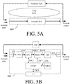
- FIG. 5A shows a forward path ( Forward Path ) and a feedback path ( Feedback Path ) of a hearing device (HD) and a corresponding loop delay ( Loop delay ) comprising a sum of the propagation delays of the forward and feedback paths.
- the loop delay may be relatively constant over time (and e.g. determined in advance of operation of the hearing device) or be different at different points in time, e.g. depending on the currently applied algorithms in the signal processing unit.
- FIG. 5B shows an embodiment of a hearing device (HD) according to the present disclosure comprising a loop delay estimation unit and a user interface.
- FIG. 5B shows an embodiment of a hearing device (HD) according to the present disclosure as shown in FIG: 4B further comprises a control unit (CONT) for estimating a current loop delay or a deviation from a typical loop delay.
- the hearing device (HD) further comprises a memory unit (MEM) wherein typical loop delays (signal LDx) in different modes of operation of the hearing device are stored.
- the control unit is configured to measure a loop delay comprising a sum of a delay of the forward path and a delay of the feedback path.
- a predefined test-signal is inserted in the forward path by the control unit (CONT), e.g. via signal SPCT to/from the signal processing unit (SPU), and its round trip travel time measured (or estimated), e.g. by identification of the test signal when it arrives in the forward path after a single propagation (or a known number of propagations) of the loop.
- a typical loop delay is of the order of ms, e.g. around 10 ms.
- the hearing device (HD) further comprises a user interface (UI) allowing a user to control functionality of the hearing device, e.g. a mode of operation (e.g. to enter or exit a particular feedback cancellation mode of operation), via control signal UICT.
- the user interface (and the hearing device) may be configured to present a current loop delay to the user (e.g. as selected or estimated by the control unit (CONT)).
- FIG. 6 shows the idea of having N time periods, each time period (of a given frequency band, FB i ) T 1 (FB i ), T 2 (FB i ), T 3 (FB i ),..., T N (FB i ) having a corresponding gain value of A 1 (FB i ), A 2 (FB i ), A 3 (FB i ),..., A N (FB i ).
- the gain pattern (and corresponding time periods) is preferably configured to conserve energy in the resulting signal compared to the signal before the modulation of the requested forward gain (e.g. on a cycle-time basis or over a longer or shorter time period depending on the application).
- N 2, the time domain signal (the wideband signal), some of the frequency bands, or each frequency band exhibiting 2 time periods T 1 (FB i ), T 2 (FB i ), and 2 corresponding gain values (or functions) A 1 (FB i ) and A 2 (FB i ), which we have referred to as T H (FB i ), T L (FB i ), A H (FB i ) and A L (FB i ), respectively in connection with FIG.
- T rep (FB i ) T H (FB i )+T L (FB i ).
- a hearing device e.g. a hearing aid
- a hearing device comprising a forward path comprising an input transducer for providing an electric input signal, a signal processing unit configured to apply a requested forward gain to the electric input signal, and an output transducer.
- the hearing device further comprises a feedback reduction unit for reducing a risk of howl due to feedback from the output transducer to the input transducer.
- the forward path and the external feedback path defines a roundtrip loop delay.
- the feedback reduction unit is configured to modulate said requested forward gain in time, to provide that the resulting forward gain exhibits a first, increased gain A H in a first time period T H and a second, reduced gain A L in a second time period T L , wherein at least one of A H , A L , T H , and T L is/are determined according to a predetermined or adaptively determined criterion including said roundtrip loop delay.
- connection or “coupled” as used herein may include wirelessly connected or coupled.
- the term “and/or” includes any and all combinations of one or more of the associated listed items. The steps of any disclosed method is not limited to the exact order stated herein, unless expressly stated otherwise.
Landscapes
- Health & Medical Sciences (AREA)
- General Health & Medical Sciences (AREA)
- Neurosurgery (AREA)
- Otolaryngology (AREA)
- Physics & Mathematics (AREA)
- Engineering & Computer Science (AREA)
- Acoustics & Sound (AREA)
- Signal Processing (AREA)
- Circuit For Audible Band Transducer (AREA)
Claims (16)
- Hörinstrument (HD), das angepasst ist, um an dem Ohr oder vollständig oder teilweise in dem Gehörgang eines Benutzers angeordnet zu sein, wobei das Hörinstrument Folgendes umfasst: einen Eingangswandler (IT) zum Umwandeln von Eingangsgeräuschen in ein elektrisches Eingangssignal (IN), das Geräusche darstellt, einen Ausgangswandler (OT) zum Umwandeln eines verarbeiteten elektrischen Ausgangssignals in Ausgangsgeräusche und eine Signalverarbeitungseinheit (SPU), die mit dem Eingangs- und Ausgangswandler wirkverbunden und konfiguriert ist, um eine angeforderte Vorwärtsverstärkung auf das elektrische Eingangssignal oder ein Signal, das seinen Ursprung darin hat, anzuwenden, wobei der Eingangswandler (IT), die Signalverarbeitungseinheit (SPU) und der Ausgangswandler (OT) Teil eines Vorwärtspfades des Hörinstruments bilden, wobei der Vorwärtspfad eine resultierende Vorwärtsverstärkung auf das elektrische Eingangssignal (IN) anwendet und ein resultierendes Signal (RES) für eine Umwandlung an den Ausgangsgeräuschen bereitstellt, wobei das Hörinstrument (HD) ferner eine Rückkopplungsverringerungseinheit (FBRU) umfasst, um ein Risiko von Aufheulen aufgrund einer akustischen oder mechanischen Rückkopplung eines externen Rückkopplungspfades (FBP) von dem Ausgangswandler (OT) zu dem Eingangswandler (IT) des Hörinstruments zu verringern, wobei der Vorwärtspfad und der externe Rückkopplungspfad einen Schleifenpfad definieren, der eine Rundlauf-Schleifenverzögerung aufweist, dadurch gekennzeichnet, dass die Rückkopplungsverringerungseinheit (FBRU) konfiguriert ist, um die angeforderte Vorwärtsverstärkung im Zeitverlauf zu modulierten, um bereitzustellen, dass die resultierende Vorwärtsverstärkung eine erste, erhöhte Verstärkung AH in einem ersten Zeitraum TH und eine zweite, verringerte Verstärkung AL in einem zweiten Zeitraum TL aufweist, wobei zumindest eines von der ersten Verstärkung AH, der zweiten Verstärkung AL, dem ersten Zeitraum TH UND dem zweiten Zeitraum TL gemäß einem vorbestimmten oder adaptiv bestimmten Kriterium bestimmt ist und wobei das Kriterium umfasst, dass der erste TH und/oder der zweite TL Zeitraum in Abhängigkeit von einer, möglicherweise durchschnittlichen, Rundlauf-Schleifenverzögerung des Vorwärtspfades und dem externen Rückkopplungspfad bestimmt sind/ist.
- Hörinstrument nach Anspruch 1, wobei die Modulation der angeforderten Vorwärtsverstärkung, die durch die Rückkopplungsverringerungseinheit (FBRU) bereitgestellt wird, ein vorbestimmtes oder adaptiv bestimmtes Verstärkungsmuster im Zeitverlauf mit vordefinierten und/oder adaptiv bestimmten und eingestellten Verstärkungen A1, A2, A3, ..., AN in entsprechenden Zeiträumen T1, T2, T3, ..., TN aufweist.
- Hörinstrument nach Anspruch 2, wobei das angewendete Verstärkungsmuster ein wiederholtes Auftreten des vordefinierten Verstärkungsmusters A1, A2, A3, ..AN, umfasst, wobei die Wiederholungszeit (oder Zykluszeit) T1 + T2 + T3 + ... + TN IST.
- Hörinstrument nach einem der vorangehenden Ansprüche 1-3, wobei das Kriterium umfasst, dass der zweite Zeitraum TL entweder ähnlich oder kleiner der Schleifenverzögerung oder einer durchschnittlichen Rundlauf-Schleifenverzögerung Tloop ausgewählt ist oder in Bezug auf die Schleifenverzögerung durch Tloop/2 < TL < Tloop ∗2 ausgewählt ist.
- Hörinstrument nach einem der Ansprüche 1-4, umfassend eine Steuereinheit (CONT) zum Schätzen einer aktuellen Schleifen- oder durchschnittlichen Schleifenverzögerung oder einer Abweichung von einer üblichen Schleifenverzögerung oder einer üblichen durchschnittlichen Schleifenverzögerung.
- Hörinstrument nach einem der Ansprüche 1-5, wobei das Kriterium umfasst, dass der erste und zweite Zeitraum und die erste und zweite Verstärkung konfiguriert sind, um Energie in dem resultierenden Signal (RES) verglichen mit dem Signal vor der Modulation der angeforderten Vorwärtsverstärkung zu sparen.
- Hörinstrument nach einem der Ansprüche 1-6, das konfiguriert ist, um bereitzustellen, dass die erhöhte Verstärkung AH und/oder die verringerte Verstärkung AL während des ersten und zweiten Zeitraums TH und TL variierbar sind/ist.
- Hörinstrument nach einem der Ansprüche 1-7, umfassend eine Zeit-zu-Zeitfrequenz-Umwandlungseinheit (FBA) zum Bereitstellen des elektrischen Eingangssignals (IN) oder eines Signals, das davon abgeleitet ist, in einer Reihe von Frequenzbändern.
- Hörinstrument nach einem der Ansprüche 1-8, das konfiguriert ist, um bereitzustellen, dass die Verstärkungsmodifizierung im Zeitverlauf in einem ausgewählten Frequenzband oder mehreren ausgewählten oder allen Frequenzbändern durchgeführt wird.
- Hörinstrument nach Anspruch 9, das angepasst ist, um bereitzustellen, dass die erhöhte Verstärkung AH und/oder die verringerte Verstärkung AL für zumindest einige der Frequenzbänder konfigurierbar sind/ist.
- Hörinstrument nach Anspruch 9 oder 10, das angepasst ist, um bereitzustellen, dass die erhöhte Verstärkung AH und/oder die verringerte Verstärkung AL lediglich in Frequenzbändern angewendet werden/wird, von denen erwartet wird, dass sie ein Risiko von Aufheulen aufweisen.
- Hörinstrument nach einem der Ansprüche 9-11, das angepasst ist, um bereitzustellen, dass die erhöhte Verstärkung AH und/oder die verringerte Verstärkung AL lediglich in Frequenzbändern über einer ersten Schwellenfrequenz fTHL angewendet werden/wird.
- Hörinstrument nach einem der vorangehenden Ansprüche, umfassend eine Hörhilfe, ein Headset, ein aktives Gehörschutzsystem oder eine Kombination davon.
- Verfahren zum Betreiben eines Hörinstruments, das angepasst ist, um an dem Ohr oder vollständig oder teilweise in dem Gehörgang eines Benutzers angeordnet zu sein, und einen Vorwärtspfad umfasst, um eine resultierende Vorwärtsverstärkung auf ein elektrisches Eingangssignal anzuwenden und ein resultierendes Signal bereitzustellen, wobei das Verfahren Folgendes umfasst:• Bereitstellen eines elektrischen Eingangssignals (IN), das Geräusche darstellt;• Anwenden einer angeforderten Vorwärtsverstärkung auf das elektrische Eingangssignal (IN) oder ein Signal, das seinen Ursprung darin hat, und Bereitstellen eines verarbeiteten Signals (ENHS);• Bereitstellen eines resultierenden Signals (RES) für eine Umwandlung in Ausgangsgeräusche; dadurch gekennzeichnet, dass das Verfahren ferner Folgendes umfasst:• Verringern eines Risikos von Aufheulen aufgrund einer akustischen oder mechanischen Rückkopplung eines externen Rückkopplungspfades, durch den die Ausgangsgeräusche in die Eingangsgeräusche eintreten, durch Modulieren der angeforderten Vorwärtsverstärkung im Zeitverlauf, um bereitzustellen, dass die resultierende Vorwärtsverstärkung eine erste, erhöhte Verstärkung AH in einem ersten Zeitraum TH und eine zweite, verringerte Verstärkung AL in einem zweiten Zeitraum TL aufweist, und• Bereitstellen, dass zumindest eines von der ersten Verstärkung AH, der zweiten Verstärkung AL, dem ersten Zeitraum TH UND dem zweiten Zeitraum TL gemäß einem vorbestimmten oder adaptiv bestimmten Kriterium bestimmt ist, wobei das vorbestimmte Kriterium umfasst, dass der erste TH und/oder der zweite TL Zeitraum in Abhängigkeit von einer, möglicherweise durchschnittlichen, Rundlauf-Schleifenverzögerung des Vorwärtspfades und dem externen Rückkopplungspfades bestimmt sind/ist.
- Verfahren nach Anspruch 14, wobei zumindest eines von der ersten, erhöhten Verstärkung AH, dem ersten Zeitraum TH, der zweiten, verringerten Verstärkung AL UND dem zweiten Zeitraum TL unter Verwendung eines Modells der menschlichen akustischen Wahrnehmung ausgewählt sind/ist, um die Modulation der angeforderten Vorwärtsverstärkung weniger hörbar oder sogar nicht hörbar für den Benutzer zu gestalten.
- Datenverarbeitungssystem, umfassend einen Prozessor und ein Programmcodemittel, um den Prozessor zu veranlassen, die Schritte des Verfahrens nach Anspruch 14 durchzuführen.
Applications Claiming Priority (1)
| Application Number | Priority Date | Filing Date | Title |
|---|---|---|---|
| EP15184008 | 2015-09-07 |
Publications (2)
| Publication Number | Publication Date |
|---|---|
| EP3139636A1 EP3139636A1 (de) | 2017-03-08 |
| EP3139636B1 true EP3139636B1 (de) | 2019-10-16 |
Family
ID=54065258
Family Applications (1)
| Application Number | Title | Priority Date | Filing Date |
|---|---|---|---|
| EP16186507.6A Active EP3139636B1 (de) | 2015-09-07 | 2016-08-31 | Hörgerät mit einem auf signalenergieverschiebung basierenden rückkopplungsunterdrückungssystem |
Country Status (4)
| Country | Link |
|---|---|
| US (2) | US9826319B2 (de) |
| EP (1) | EP3139636B1 (de) |
| CN (1) | CN106507258B (de) |
| DK (1) | DK3139636T3 (de) |
Families Citing this family (12)
| Publication number | Priority date | Publication date | Assignee | Title |
|---|---|---|---|---|
| EP3139636B1 (de) * | 2015-09-07 | 2019-10-16 | Oticon A/s | Hörgerät mit einem auf signalenergieverschiebung basierenden rückkopplungsunterdrückungssystem |
| EP3188507A1 (de) | 2015-12-30 | 2017-07-05 | GN Resound A/S | Am kopf tragbares hörgerät |
| WO2018112188A1 (en) * | 2016-12-14 | 2018-06-21 | Waveguide Corporation | Variable gain amplification for linearization of nmr signals |
| US10616685B2 (en) * | 2016-12-22 | 2020-04-07 | Gn Hearing A/S | Method and device for streaming communication between hearing devices |
| EP3905724B1 (de) * | 2017-04-06 | 2024-07-31 | Oticon A/s | Verfahren zur binauralen pegelschätzung und hörsystem mit einem binauralen pegelschätzer |
| CN113766073B (zh) * | 2017-09-29 | 2024-04-16 | 杜比实验室特许公司 | 会议系统中的啸叫检测 |
| EP3481085B1 (de) | 2017-11-01 | 2020-09-09 | Oticon A/s | Rückkopplungsdetektor und hörgerät mit einem rückkopplungsdetektor |
| EP3525489B1 (de) | 2018-02-09 | 2021-05-12 | Oticon A/s | Verfahren zur anpassung eines hörgeräts an die bedürfnisse eines benutzers, programmierungsvorrichtung und hörgerät |
| US10931516B2 (en) * | 2018-09-26 | 2021-02-23 | Hewlett Packard Enterprise Development Lp | Network link failure detection |
| EP4064730A1 (de) * | 2021-03-26 | 2022-09-28 | Oticon A/s | Bewegungsdatenbasierte signalverarbeitung |
| EP4064731A1 (de) | 2021-03-26 | 2022-09-28 | Oticon A/s | Verbesserte rückkopplungsunterdrückung in einem hörgerät |
| EP4132009A3 (de) | 2021-08-05 | 2023-02-22 | Oticon A/s | Hörgerät mit rückkopplungssteuerungssystem |
Family Cites Families (69)
| Publication number | Priority date | Publication date | Assignee | Title |
|---|---|---|---|---|
| JP2954328B2 (ja) * | 1990-06-27 | 1999-09-27 | 株式会社日立製作所 | 映像信号の記録再生装置 |
| US5786778A (en) * | 1995-10-05 | 1998-07-28 | Analog Devices, Inc. | Variable sample-rate DAC/ADC/converter system |
| US6072884A (en) * | 1997-11-18 | 2000-06-06 | Audiologic Hearing Systems Lp | Feedback cancellation apparatus and methods |
| US6434246B1 (en) * | 1995-10-10 | 2002-08-13 | Gn Resound As | Apparatus and methods for combining audio compression and feedback cancellation in a hearing aid |
| US6137888A (en) * | 1997-06-02 | 2000-10-24 | Nortel Networks Corporation | EM interference canceller in an audio amplifier |
| US6498858B2 (en) * | 1997-11-18 | 2002-12-24 | Gn Resound A/S | Feedback cancellation improvements |
| US6219427B1 (en) * | 1997-11-18 | 2001-04-17 | Gn Resound As | Feedback cancellation improvements |
| US6480610B1 (en) * | 1999-09-21 | 2002-11-12 | Sonic Innovations, Inc. | Subband acoustic feedback cancellation in hearing aids |
| EP1438873A1 (de) * | 2001-10-17 | 2004-07-21 | Oticon A/S | Verbessertes hörgerät |
| US20040240690A1 (en) * | 2003-05-27 | 2004-12-02 | Blamey Peter J. | Oscillation detection |
| WO2005020632A1 (en) * | 2003-08-21 | 2005-03-03 | Widex A/S | Hearing aid with acoustic feedback suppression |
| US7519193B2 (en) * | 2003-09-03 | 2009-04-14 | Resistance Technology, Inc. | Hearing aid circuit reducing feedback |
| DE602004017648D1 (de) * | 2004-03-03 | 2008-12-18 | Widex As | Hörgerät mit adaptivem rückkopplungsunterdrückungssystem |
| US20070106530A1 (en) * | 2004-05-26 | 2007-05-10 | Blamey Peter J | Oscillation suppression |
| CN101084697B (zh) * | 2004-12-16 | 2011-10-19 | 唯听助听器公司 | 具有反馈模型增益估计的助听器 |
| US8096937B2 (en) * | 2005-01-11 | 2012-01-17 | Otologics, Llc | Adaptive cancellation system for implantable hearing instruments |
| US8477952B2 (en) * | 2005-04-27 | 2013-07-02 | Oticon A/S | Audio system with feedback detection means |
| WO2007101477A1 (en) * | 2006-03-09 | 2007-09-13 | Widex A/S | Hearing aid with adaptive feedback suppression |
| US8553899B2 (en) * | 2006-03-13 | 2013-10-08 | Starkey Laboratories, Inc. | Output phase modulation entrainment containment for digital filters |
| US8116473B2 (en) * | 2006-03-13 | 2012-02-14 | Starkey Laboratories, Inc. | Output phase modulation entrainment containment for digital filters |
| CA2647462C (en) * | 2006-04-01 | 2014-05-20 | Widex A/S | Hearing aid, and a method for control of adaptation rate in anti-feedback systems for hearing aids |
| DK2003928T3 (en) * | 2007-06-12 | 2019-01-28 | Oticon As | Online anti-feedback system for a hearing aid |
| EP2015604A1 (de) * | 2007-07-10 | 2009-01-14 | Oticon A/S | Erzeugung eines Sondengeräuschs in einem Rückkopplungsunterdrückungssystem |
| EP2046073B1 (de) * | 2007-10-03 | 2017-03-08 | Oticon A/S | Hörgerätsystem mit Rückkoppelungsanordnung zur Vorhersage und Unterdrückung von akustischer Rückkoppelung |
| EP2227915B1 (de) * | 2007-12-07 | 2019-05-15 | Cirrus Logic International Semiconductor Limited | Mitnahmebeständige rückkopplungslöschung |
| EP2475192A3 (de) * | 2007-12-11 | 2015-04-01 | Bernafon AG | Hörgerätsystem mit einem angepassten Filter und Messverfahren |
| EP2232890A2 (de) * | 2008-01-22 | 2010-09-29 | Phonak AG | Verfahren zur bestimmung eines maximalen verstärkungsfaktors in einem hörgerät und hörgerät |
| US8340333B2 (en) * | 2008-02-29 | 2012-12-25 | Sonic Innovations, Inc. | Hearing aid noise reduction method, system, and apparatus |
| WO2009124550A1 (en) * | 2008-04-10 | 2009-10-15 | Gn Resound A/S | An audio system with feedback cancellation |
| EP2148527B1 (de) | 2008-07-24 | 2014-04-16 | Oticon A/S | System zur Reduzierung der akustischen Rückkopplung in Hörhilfen unter Verwendung von interauraler Signalübertragung, Verfahren und Verwendung |
| US8767987B2 (en) * | 2008-08-12 | 2014-07-01 | Intricon Corporation | Ear contact pressure wave hearing aid switch |
| US8554350B2 (en) * | 2008-10-15 | 2013-10-08 | Personics Holdings Inc. | Device and method to reduce ear wax clogging of acoustic ports, hearing aid sealing system, and feedback reduction system |
| EP2442590B1 (de) * | 2008-11-24 | 2014-07-02 | Oticon A/S | Verfahren zur Rückmeldungsreduktion in Hörgeräten |
| EP2192794B1 (de) * | 2008-11-26 | 2017-10-04 | Oticon A/S | Verbesserungen für Hörgerätalgorithmen |
| AU2009339343A1 (en) * | 2009-02-06 | 2011-08-18 | Oticon A/S | Spectral band substitution to avoid howls and sub-oscillation |
| DK2237573T3 (da) * | 2009-04-02 | 2021-05-03 | Oticon As | Adaptiv feedbackundertrykkelsesfremgangsmåde og anordning dertil |
| EP2621198A3 (de) * | 2009-04-02 | 2015-03-25 | Oticon A/s | Verfahren zur adaptiven Rückkopplungsunterdrückung und Vorrichtung dafür |
| EP2284833A1 (de) * | 2009-08-03 | 2011-02-16 | Bernafon AG | Verfahren zur Überwachung des Einflusses von Umgebungsgeräuschen auf ein adaptives Filter zur akustischen Rückkoplungsunterdrückung |
| DK2309777T3 (da) * | 2009-09-14 | 2013-02-04 | Gn Resound As | Et høreapparat med organer til at de-korrelere indgangs- og udgangssignaler |
| US9729976B2 (en) * | 2009-12-22 | 2017-08-08 | Starkey Laboratories, Inc. | Acoustic feedback event monitoring system for hearing assistance devices |
| DK2360944T3 (en) * | 2010-02-01 | 2018-02-26 | Oticon As | Method of Suppressing Acoustic Feedback in a Hearing Device and Similar Hearing Device |
| US8630437B2 (en) * | 2010-02-23 | 2014-01-14 | University Of Utah Research Foundation | Offending frequency suppression in hearing aids |
| DE102010011729A1 (de) * | 2010-03-17 | 2011-09-22 | Siemens Medical Instruments Pte. Ltd. | Hörvorrichtung und Verfahren zum Einstellen derselben für einen rückkopplungsfreien Betrieb |
| US8942398B2 (en) * | 2010-04-13 | 2015-01-27 | Starkey Laboratories, Inc. | Methods and apparatus for early audio feedback cancellation for hearing assistance devices |
| EP2523471B1 (de) * | 2011-05-09 | 2014-06-18 | Bernafon AG | Testsystem zur Beurteilung der Feedbackleistung einer Hörvorrichtung |
| DK2541973T3 (da) * | 2011-06-27 | 2014-07-14 | Oticon As | Tilbagekoblingsstyring i en lytteanordning |
| DK2581038T3 (en) * | 2011-10-14 | 2018-02-19 | Oticon As | Automatic real-time hearing aid fitting based on auditory evoked potentials |
| DK2613567T3 (da) * | 2012-01-03 | 2014-10-27 | Oticon As | Fremgangsmåde til forbedring af et langtidstilbagekoblingsvejestimat i en lytteanordning |
| DK2613566T3 (en) * | 2012-01-03 | 2016-10-17 | Oticon As | A listening device and method for monitoring the placement of an earplug for a listening device |
| EP2661103A1 (de) * | 2012-05-02 | 2013-11-06 | Oticon A/s | Verfahren zum Anpassen eines Hörgeräts |
| KR101231866B1 (ko) * | 2012-09-11 | 2013-02-08 | (주)알고코리아 | 귀환소음을 제거하기위한 보청기시스템 및 그 제어방법 |
| EP2736271B1 (de) * | 2012-11-27 | 2019-06-19 | Oticon A/s | Verfahren zur Steuerung eines Aktualisierungsalgorithmus eines adaptiven Rückkopplungsschätzsystems und eine De-Korrelierungseinheit |
| US9148735B2 (en) * | 2012-12-28 | 2015-09-29 | Gn Resound A/S | Hearing aid with improved localization |
| US9148733B2 (en) * | 2012-12-28 | 2015-09-29 | Gn Resound A/S | Hearing aid with improved localization |
| US9020172B2 (en) * | 2013-03-15 | 2015-04-28 | Cochlear Limited | Methods, systems, and devices for detecting feedback |
| US9100762B2 (en) * | 2013-05-22 | 2015-08-04 | Gn Resound A/S | Hearing aid with improved localization |
| EP3917167A3 (de) * | 2013-06-14 | 2022-03-09 | Oticon A/s | Hörhilfevorrichtung mit Gehirn-Computer-Schnittstelle |
| DK2822263T3 (da) | 2013-07-05 | 2019-06-17 | Sennheiser Communications As | Kommunikationsanordning med ekkoundertrykkelse |
| DK2846559T3 (en) * | 2013-09-05 | 2019-01-21 | Oticon As | Method of performing a RECD measurement using a hearing aid device |
| US20170188147A1 (en) * | 2013-09-26 | 2017-06-29 | Universidade Do Porto | Acoustic feedback cancellation based on cesptral analysis |
| EP2882203A1 (de) * | 2013-12-06 | 2015-06-10 | Oticon A/s | Hörgerätevorrichtung für freihändige Kommunikation |
| EP2950555A1 (de) * | 2014-05-28 | 2015-12-02 | Oticon A/s | Automatische Echtzeit-Hörgeräteanpassung basierend auf auditorisch evorzierten Potentialen, die durch natürliche Tonsignale erzeugt werden |
| DE102014215165A1 (de) * | 2014-08-01 | 2016-02-18 | Sivantos Pte. Ltd. | Verfahren und Vorrichtung zur Rückkopplungsunterdrückung |
| EP2982296A1 (de) * | 2014-08-07 | 2016-02-10 | Oticon A/s | Hörhilfesystem mit verbesserter Signalverarbeitung mit einem implantierten Teil |
| EP2988529B1 (de) * | 2014-08-20 | 2019-12-04 | Sivantos Pte. Ltd. | Adaptive teilungsfrequenz in hörhilfegeräten |
| EP3016407B1 (de) * | 2014-10-28 | 2019-12-11 | Oticon A/s | Hörsystem zur Schätzung eines Rückkopplungspfads eines Hörgeräts |
| US9838804B2 (en) * | 2015-02-27 | 2017-12-05 | Cochlear Limited | Methods, systems, and devices for adaptively filtering audio signals |
| EP3139636B1 (de) * | 2015-09-07 | 2019-10-16 | Oticon A/s | Hörgerät mit einem auf signalenergieverschiebung basierenden rückkopplungsunterdrückungssystem |
| DK3148214T3 (da) * | 2015-09-15 | 2022-01-03 | Oticon As | Høreanordning der omfatter et forbedret feedback-annulleringssystem |
-
2016
- 2016-08-31 EP EP16186507.6A patent/EP3139636B1/de active Active
- 2016-08-31 DK DK16186507T patent/DK3139636T3/da active
- 2016-09-06 US US15/257,295 patent/US9826319B2/en not_active Expired - Fee Related
- 2016-09-06 CN CN201610806853.3A patent/CN106507258B/zh active Active
-
2017
- 2017-10-17 US US15/785,927 patent/US10200796B2/en active Active
Non-Patent Citations (1)
| Title |
|---|
| None * |
Also Published As
| Publication number | Publication date |
|---|---|
| US20180041845A1 (en) | 2018-02-08 |
| US10200796B2 (en) | 2019-02-05 |
| CN106507258A (zh) | 2017-03-15 |
| EP3139636A1 (de) | 2017-03-08 |
| DK3139636T3 (da) | 2019-12-09 |
| US20170070827A1 (en) | 2017-03-09 |
| US9826319B2 (en) | 2017-11-21 |
| CN106507258B (zh) | 2020-09-11 |
Similar Documents
| Publication | Publication Date | Title |
|---|---|---|
| US10200796B2 (en) | Hearing device comprising a feedback cancellation system based on signal energy relocation | |
| US11245993B2 (en) | Hearing device comprising a noise reduction system | |
| US10659891B2 (en) | Hearing device comprising a feedback detection unit | |
| EP3148214B1 (de) | Hörgerät mit einem verbesserten system zur beseitigung von rückkopplung | |
| EP3506658B1 (de) | Hörgerät mit einem zur platzierung am oder im gehörgang eines benutzers angepassten mikrofon | |
| EP3481085B1 (de) | Rückkopplungsdetektor und hörgerät mit einem rückkopplungsdetektor | |
| US9712928B2 (en) | Binaural hearing system | |
| EP3220661B1 (de) | Verfahren zur vorhersage der verständlichkeit von verrauschter und/oder erweiterter sprache und binaurales hörsystem | |
| US11863938B2 (en) | Hearing aid determining turn-taking | |
| US11330375B2 (en) | Method of adaptive mixing of uncorrelated or correlated noisy signals, and a hearing device | |
| US12621613B2 (en) | Method of detecting a sudden change in a feedback/echo path of a hearing aid | |
| US10321243B2 (en) | Hearing device comprising a filterbank and an onset detector | |
| EP3525489A1 (de) | Verfahren zur anpassung eines hörgeräts an die bedürfnisse eines benutzers, programmierungsvorrichtung und hörgerät |
Legal Events
| Date | Code | Title | Description |
|---|---|---|---|
| PUAI | Public reference made under article 153(3) epc to a published international application that has entered the european phase |
Free format text: ORIGINAL CODE: 0009012 |
|
| STAA | Information on the status of an ep patent application or granted ep patent |
Free format text: STATUS: THE APPLICATION HAS BEEN PUBLISHED |
|
| AK | Designated contracting states |
Kind code of ref document: A1 Designated state(s): AL AT BE BG CH CY CZ DE DK EE ES FI FR GB GR HR HU IE IS IT LI LT LU LV MC MK MT NL NO PL PT RO RS SE SI SK SM TR |
|
| AX | Request for extension of the european patent |
Extension state: BA ME |
|
| STAA | Information on the status of an ep patent application or granted ep patent |
Free format text: STATUS: REQUEST FOR EXAMINATION WAS MADE |
|
| 17P | Request for examination filed |
Effective date: 20170908 |
|
| RBV | Designated contracting states (corrected) |
Designated state(s): AL AT BE BG CH CY CZ DE DK EE ES FI FR GB GR HR HU IE IS IT LI LT LU LV MC MK MT NL NO PL PT RO RS SE SI SK SM TR |
|
| STAA | Information on the status of an ep patent application or granted ep patent |
Free format text: STATUS: EXAMINATION IS IN PROGRESS |
|
| 17Q | First examination report despatched |
Effective date: 20180420 |
|
| GRAJ | Information related to disapproval of communication of intention to grant by the applicant or resumption of examination proceedings by the epo deleted |
Free format text: ORIGINAL CODE: EPIDOSDIGR1 |
|
| STAA | Information on the status of an ep patent application or granted ep patent |
Free format text: STATUS: GRANT OF PATENT IS INTENDED |
|
| GRAP | Despatch of communication of intention to grant a patent |
Free format text: ORIGINAL CODE: EPIDOSNIGR1 |
|
| INTG | Intention to grant announced |
Effective date: 20190508 |
|
| GRAS | Grant fee paid |
Free format text: ORIGINAL CODE: EPIDOSNIGR3 |
|
| GRAA | (expected) grant |
Free format text: ORIGINAL CODE: 0009210 |
|
| STAA | Information on the status of an ep patent application or granted ep patent |
Free format text: STATUS: THE PATENT HAS BEEN GRANTED |
|
| AK | Designated contracting states |
Kind code of ref document: B1 Designated state(s): AL AT BE BG CH CY CZ DE DK EE ES FI FR GB GR HR HU IE IS IT LI LT LU LV MC MK MT NL NO PL PT RO RS SE SI SK SM TR |
|
| REG | Reference to a national code |
Ref country code: GB Ref legal event code: FG4D |
|
| REG | Reference to a national code |
Ref country code: CH Ref legal event code: EP |
|
| REG | Reference to a national code |
Ref country code: DE Ref legal event code: R096 Ref document number: 602016022475 Country of ref document: DE |
|
| REG | Reference to a national code |
Ref country code: IE Ref legal event code: FG4D |
|
| REG | Reference to a national code |
Ref country code: AT Ref legal event code: REF Ref document number: 1192498 Country of ref document: AT Kind code of ref document: T Effective date: 20191115 |
|
| REG | Reference to a national code |
Ref country code: DK Ref legal event code: T3 Effective date: 20191203 |
|
| RAP2 | Party data changed (patent owner data changed or rights of a patent transferred) |
Owner name: OTICON A/S |
|
| REG | Reference to a national code |
Ref country code: NL Ref legal event code: MP Effective date: 20191016 |
|
| REG | Reference to a national code |
Ref country code: LT Ref legal event code: MG4D |
|
| REG | Reference to a national code |
Ref country code: AT Ref legal event code: MK05 Ref document number: 1192498 Country of ref document: AT Kind code of ref document: T Effective date: 20191016 |
|
| PG25 | Lapsed in a contracting state [announced via postgrant information from national office to epo] |
Ref country code: SE Free format text: LAPSE BECAUSE OF FAILURE TO SUBMIT A TRANSLATION OF THE DESCRIPTION OR TO PAY THE FEE WITHIN THE PRESCRIBED TIME-LIMIT Effective date: 20191016 Ref country code: LV Free format text: LAPSE BECAUSE OF FAILURE TO SUBMIT A TRANSLATION OF THE DESCRIPTION OR TO PAY THE FEE WITHIN THE PRESCRIBED TIME-LIMIT Effective date: 20191016 Ref country code: AT Free format text: LAPSE BECAUSE OF FAILURE TO SUBMIT A TRANSLATION OF THE DESCRIPTION OR TO PAY THE FEE WITHIN THE PRESCRIBED TIME-LIMIT Effective date: 20191016 Ref country code: LT Free format text: LAPSE BECAUSE OF FAILURE TO SUBMIT A TRANSLATION OF THE DESCRIPTION OR TO PAY THE FEE WITHIN THE PRESCRIBED TIME-LIMIT Effective date: 20191016 Ref country code: PL Free format text: LAPSE BECAUSE OF FAILURE TO SUBMIT A TRANSLATION OF THE DESCRIPTION OR TO PAY THE FEE WITHIN THE PRESCRIBED TIME-LIMIT Effective date: 20191016 Ref country code: NL Free format text: LAPSE BECAUSE OF FAILURE TO SUBMIT A TRANSLATION OF THE DESCRIPTION OR TO PAY THE FEE WITHIN THE PRESCRIBED TIME-LIMIT Effective date: 20191016 Ref country code: PT Free format text: LAPSE BECAUSE OF FAILURE TO SUBMIT A TRANSLATION OF THE DESCRIPTION OR TO PAY THE FEE WITHIN THE PRESCRIBED TIME-LIMIT Effective date: 20200217 Ref country code: GR Free format text: LAPSE BECAUSE OF FAILURE TO SUBMIT A TRANSLATION OF THE DESCRIPTION OR TO PAY THE FEE WITHIN THE PRESCRIBED TIME-LIMIT Effective date: 20200117 Ref country code: NO Free format text: LAPSE BECAUSE OF FAILURE TO SUBMIT A TRANSLATION OF THE DESCRIPTION OR TO PAY THE FEE WITHIN THE PRESCRIBED TIME-LIMIT Effective date: 20200116 Ref country code: BG Free format text: LAPSE BECAUSE OF FAILURE TO SUBMIT A TRANSLATION OF THE DESCRIPTION OR TO PAY THE FEE WITHIN THE PRESCRIBED TIME-LIMIT Effective date: 20200116 Ref country code: FI Free format text: LAPSE BECAUSE OF FAILURE TO SUBMIT A TRANSLATION OF THE DESCRIPTION OR TO PAY THE FEE WITHIN THE PRESCRIBED TIME-LIMIT Effective date: 20191016 |
|
| PG25 | Lapsed in a contracting state [announced via postgrant information from national office to epo] |
Ref country code: RS Free format text: LAPSE BECAUSE OF FAILURE TO SUBMIT A TRANSLATION OF THE DESCRIPTION OR TO PAY THE FEE WITHIN THE PRESCRIBED TIME-LIMIT Effective date: 20191016 Ref country code: HR Free format text: LAPSE BECAUSE OF FAILURE TO SUBMIT A TRANSLATION OF THE DESCRIPTION OR TO PAY THE FEE WITHIN THE PRESCRIBED TIME-LIMIT Effective date: 20191016 Ref country code: IS Free format text: LAPSE BECAUSE OF FAILURE TO SUBMIT A TRANSLATION OF THE DESCRIPTION OR TO PAY THE FEE WITHIN THE PRESCRIBED TIME-LIMIT Effective date: 20200224 |
|
| PG25 | Lapsed in a contracting state [announced via postgrant information from national office to epo] |
Ref country code: AL Free format text: LAPSE BECAUSE OF FAILURE TO SUBMIT A TRANSLATION OF THE DESCRIPTION OR TO PAY THE FEE WITHIN THE PRESCRIBED TIME-LIMIT Effective date: 20191016 |
|
| REG | Reference to a national code |
Ref country code: DE Ref legal event code: R097 Ref document number: 602016022475 Country of ref document: DE |
|
| PG2D | Information on lapse in contracting state deleted |
Ref country code: IS |
|
| PG25 | Lapsed in a contracting state [announced via postgrant information from national office to epo] |
Ref country code: RO Free format text: LAPSE BECAUSE OF FAILURE TO SUBMIT A TRANSLATION OF THE DESCRIPTION OR TO PAY THE FEE WITHIN THE PRESCRIBED TIME-LIMIT Effective date: 20191016 Ref country code: CZ Free format text: LAPSE BECAUSE OF FAILURE TO SUBMIT A TRANSLATION OF THE DESCRIPTION OR TO PAY THE FEE WITHIN THE PRESCRIBED TIME-LIMIT Effective date: 20191016 Ref country code: ES Free format text: LAPSE BECAUSE OF FAILURE TO SUBMIT A TRANSLATION OF THE DESCRIPTION OR TO PAY THE FEE WITHIN THE PRESCRIBED TIME-LIMIT Effective date: 20191016 Ref country code: EE Free format text: LAPSE BECAUSE OF FAILURE TO SUBMIT A TRANSLATION OF THE DESCRIPTION OR TO PAY THE FEE WITHIN THE PRESCRIBED TIME-LIMIT Effective date: 20191016 Ref country code: IS Free format text: LAPSE BECAUSE OF FAILURE TO SUBMIT A TRANSLATION OF THE DESCRIPTION OR TO PAY THE FEE WITHIN THE PRESCRIBED TIME-LIMIT Effective date: 20200216 |
|
| PLBE | No opposition filed within time limit |
Free format text: ORIGINAL CODE: 0009261 |
|
| STAA | Information on the status of an ep patent application or granted ep patent |
Free format text: STATUS: NO OPPOSITION FILED WITHIN TIME LIMIT |
|
| PG25 | Lapsed in a contracting state [announced via postgrant information from national office to epo] |
Ref country code: IT Free format text: LAPSE BECAUSE OF FAILURE TO SUBMIT A TRANSLATION OF THE DESCRIPTION OR TO PAY THE FEE WITHIN THE PRESCRIBED TIME-LIMIT Effective date: 20191016 Ref country code: SM Free format text: LAPSE BECAUSE OF FAILURE TO SUBMIT A TRANSLATION OF THE DESCRIPTION OR TO PAY THE FEE WITHIN THE PRESCRIBED TIME-LIMIT Effective date: 20191016 Ref country code: SK Free format text: LAPSE BECAUSE OF FAILURE TO SUBMIT A TRANSLATION OF THE DESCRIPTION OR TO PAY THE FEE WITHIN THE PRESCRIBED TIME-LIMIT Effective date: 20191016 |
|
| 26N | No opposition filed |
Effective date: 20200717 |
|
| PG25 | Lapsed in a contracting state [announced via postgrant information from national office to epo] |
Ref country code: SI Free format text: LAPSE BECAUSE OF FAILURE TO SUBMIT A TRANSLATION OF THE DESCRIPTION OR TO PAY THE FEE WITHIN THE PRESCRIBED TIME-LIMIT Effective date: 20191016 |
|
| PG25 | Lapsed in a contracting state [announced via postgrant information from national office to epo] |
Ref country code: MC Free format text: LAPSE BECAUSE OF FAILURE TO SUBMIT A TRANSLATION OF THE DESCRIPTION OR TO PAY THE FEE WITHIN THE PRESCRIBED TIME-LIMIT Effective date: 20191016 |
|
| PG25 | Lapsed in a contracting state [announced via postgrant information from national office to epo] |
Ref country code: LU Free format text: LAPSE BECAUSE OF NON-PAYMENT OF DUE FEES Effective date: 20200831 |
|
| REG | Reference to a national code |
Ref country code: BE Ref legal event code: MM Effective date: 20200831 |
|
| PG25 | Lapsed in a contracting state [announced via postgrant information from national office to epo] |
Ref country code: IE Free format text: LAPSE BECAUSE OF NON-PAYMENT OF DUE FEES Effective date: 20200831 Ref country code: BE Free format text: LAPSE BECAUSE OF NON-PAYMENT OF DUE FEES Effective date: 20200831 |
|
| PG25 | Lapsed in a contracting state [announced via postgrant information from national office to epo] |
Ref country code: TR Free format text: LAPSE BECAUSE OF FAILURE TO SUBMIT A TRANSLATION OF THE DESCRIPTION OR TO PAY THE FEE WITHIN THE PRESCRIBED TIME-LIMIT Effective date: 20191016 Ref country code: MT Free format text: LAPSE BECAUSE OF FAILURE TO SUBMIT A TRANSLATION OF THE DESCRIPTION OR TO PAY THE FEE WITHIN THE PRESCRIBED TIME-LIMIT Effective date: 20191016 Ref country code: CY Free format text: LAPSE BECAUSE OF FAILURE TO SUBMIT A TRANSLATION OF THE DESCRIPTION OR TO PAY THE FEE WITHIN THE PRESCRIBED TIME-LIMIT Effective date: 20191016 |
|
| PG25 | Lapsed in a contracting state [announced via postgrant information from national office to epo] |
Ref country code: MK Free format text: LAPSE BECAUSE OF FAILURE TO SUBMIT A TRANSLATION OF THE DESCRIPTION OR TO PAY THE FEE WITHIN THE PRESCRIBED TIME-LIMIT Effective date: 20191016 |
|
| REG | Reference to a national code |
Ref country code: DE Ref legal event code: R081 Ref document number: 602016022475 Country of ref document: DE Owner name: OTICON A/S, DK Free format text: FORMER OWNERS: BERNAFON AG, BERN, CH; OTICON A/S, SMOERUM, DK |
|
| REG | Reference to a national code |
Ref country code: GB Ref legal event code: 732E Free format text: REGISTERED BETWEEN 20221006 AND 20221012 |
|
| PGFP | Annual fee paid to national office [announced via postgrant information from national office to epo] |
Ref country code: GB Payment date: 20250626 Year of fee payment: 10 Ref country code: DK Payment date: 20250625 Year of fee payment: 10 |
|
| PGFP | Annual fee paid to national office [announced via postgrant information from national office to epo] |
Ref country code: FR Payment date: 20250626 Year of fee payment: 10 |
|
| PGFP | Annual fee paid to national office [announced via postgrant information from national office to epo] |
Ref country code: DE Payment date: 20250627 Year of fee payment: 10 |
|
| PGFP | Annual fee paid to national office [announced via postgrant information from national office to epo] |
Ref country code: CH Payment date: 20250901 Year of fee payment: 10 |