EP3140020B1 - Koaleszenzelement einer wasserabscheidevorrichtung und wasserabscheidevorrichtung - Google Patents
Koaleszenzelement einer wasserabscheidevorrichtung und wasserabscheidevorrichtung Download PDFInfo
- Publication number
- EP3140020B1 EP3140020B1 EP15723445.1A EP15723445A EP3140020B1 EP 3140020 B1 EP3140020 B1 EP 3140020B1 EP 15723445 A EP15723445 A EP 15723445A EP 3140020 B1 EP3140020 B1 EP 3140020B1
- Authority
- EP
- European Patent Office
- Prior art keywords
- fuel
- medium
- coalescence
- water
- filter
- Prior art date
- Legal status (The legal status is an assumption and is not a legal conclusion. Google has not performed a legal analysis and makes no representation as to the accuracy of the status listed.)
- Active
Links
Images



Classifications
-
- B—PERFORMING OPERATIONS; TRANSPORTING
- B01—PHYSICAL OR CHEMICAL PROCESSES OR APPARATUS IN GENERAL
- B01D—SEPARATION
- B01D36/00—Filter circuits or combinations of filters with other separating devices
- B01D36/003—Filters in combination with devices for the removal of liquids
-
- B—PERFORMING OPERATIONS; TRANSPORTING
- B01—PHYSICAL OR CHEMICAL PROCESSES OR APPARATUS IN GENERAL
- B01D—SEPARATION
- B01D29/00—Filters with filtering elements stationary during filtration, e.g. pressure or suction filters, not covered by groups B01D24/00 - B01D27/00; Filtering elements therefor
- B01D29/11—Filters with filtering elements stationary during filtration, e.g. pressure or suction filters, not covered by groups B01D24/00 - B01D27/00; Filtering elements therefor with bag, cage, hose, tube, sleeve or like filtering elements
- B01D29/13—Supported filter elements
- B01D29/15—Supported filter elements arranged for inward flow filtration
-
- B—PERFORMING OPERATIONS; TRANSPORTING
- B01—PHYSICAL OR CHEMICAL PROCESSES OR APPARATUS IN GENERAL
- B01D—SEPARATION
- B01D35/00—Filtering devices having features not specifically covered by groups B01D24/00 - B01D33/00, or for applications not specifically covered by groups B01D24/00 - B01D33/00; Auxiliary devices for filtration; Filter housing constructions
- B01D35/005—Filters specially adapted for use in internal-combustion engine lubrication or fuel systems
-
- F—MECHANICAL ENGINEERING; LIGHTING; HEATING; WEAPONS; BLASTING
- F02—COMBUSTION ENGINES; HOT-GAS OR COMBUSTION-PRODUCT ENGINE PLANTS
- F02M—SUPPLYING COMBUSTION ENGINES IN GENERAL WITH COMBUSTIBLE MIXTURES OR CONSTITUENTS THEREOF
- F02M37/00—Apparatus or systems for feeding liquid fuel from storage containers to carburettors or fuel-injection apparatus; Arrangements for purifying liquid fuel specially adapted for, or arranged on, internal-combustion engines
- F02M37/22—Arrangements for purifying liquid fuel specially adapted for, or arranged on, internal-combustion engines, e.g. arrangements in the feeding system
- F02M37/24—Arrangements for purifying liquid fuel specially adapted for, or arranged on, internal-combustion engines, e.g. arrangements in the feeding system characterised by water separating means
-
- F—MECHANICAL ENGINEERING; LIGHTING; HEATING; WEAPONS; BLASTING
- F02—COMBUSTION ENGINES; HOT-GAS OR COMBUSTION-PRODUCT ENGINE PLANTS
- F02M—SUPPLYING COMBUSTION ENGINES IN GENERAL WITH COMBUSTIBLE MIXTURES OR CONSTITUENTS THEREOF
- F02M37/00—Apparatus or systems for feeding liquid fuel from storage containers to carburettors or fuel-injection apparatus; Arrangements for purifying liquid fuel specially adapted for, or arranged on, internal-combustion engines
- F02M37/22—Arrangements for purifying liquid fuel specially adapted for, or arranged on, internal-combustion engines, e.g. arrangements in the feeding system
- F02M37/24—Arrangements for purifying liquid fuel specially adapted for, or arranged on, internal-combustion engines, e.g. arrangements in the feeding system characterised by water separating means
- F02M37/26—Arrangements for purifying liquid fuel specially adapted for, or arranged on, internal-combustion engines, e.g. arrangements in the feeding system characterised by water separating means with water detection means
- F02M37/28—Arrangements for purifying liquid fuel specially adapted for, or arranged on, internal-combustion engines, e.g. arrangements in the feeding system characterised by water separating means with water detection means with means activated by the presence of water, e.g. alarms or means for automatic drainage
-
- F—MECHANICAL ENGINEERING; LIGHTING; HEATING; WEAPONS; BLASTING
- F02—COMBUSTION ENGINES; HOT-GAS OR COMBUSTION-PRODUCT ENGINE PLANTS
- F02M—SUPPLYING COMBUSTION ENGINES IN GENERAL WITH COMBUSTIBLE MIXTURES OR CONSTITUENTS THEREOF
- F02M37/00—Apparatus or systems for feeding liquid fuel from storage containers to carburettors or fuel-injection apparatus; Arrangements for purifying liquid fuel specially adapted for, or arranged on, internal-combustion engines
- F02M37/22—Arrangements for purifying liquid fuel specially adapted for, or arranged on, internal-combustion engines, e.g. arrangements in the feeding system
- F02M37/32—Arrangements for purifying liquid fuel specially adapted for, or arranged on, internal-combustion engines, e.g. arrangements in the feeding system characterised by filters or filter arrangements
- F02M37/34—Arrangements for purifying liquid fuel specially adapted for, or arranged on, internal-combustion engines, e.g. arrangements in the feeding system characterised by filters or filter arrangements by the filter structure, e.g. honeycomb, mesh or fibrous
Definitions
- the invention relates to a coalescing element of a water separation device, in particular a fuel filter, for fuel, in particular diesel fuel, in particular with at least one additive, in particular an internal combustion engine, in particular a motor vehicle, which can be arranged in a housing of the water separation device so that there is at least one fuel inlet of the housing separates from at least one fuel outlet, wherein at least one coalescing medium for separating water contained in the fuel is arranged in the flow path of the fuel.
- a coalescing element of a water separation device in particular a fuel filter, for fuel, in particular diesel fuel, in particular with at least one additive, in particular an internal combustion engine, in particular a motor vehicle, which can be arranged in a housing of the water separation device so that there is at least one fuel inlet of the housing separates from at least one fuel outlet, wherein at least one coalescing medium for separating water contained in the fuel is arranged in the flow path of the fuel.
- the invention relates to a water separation device, in particular a fuel filter, for fuel, in particular diesel fuel, in particular with at least one additive, in particular an internal combustion engine, in particular a motor vehicle, with a housing which has at least one fuel inlet for fuel to be treated, in particular to be cleaned, at least has a fuel outlet for treated fuel and at least one water outlet for water separated from the fuel, with at least one coalescing medium for separating water contained in the fuel being arranged in the flow path of the fuel.
- a water separation device in particular a fuel filter, for fuel, in particular diesel fuel, in particular with at least one additive, in particular an internal combustion engine, in particular a motor vehicle, with a housing which has at least one fuel inlet for fuel to be treated, in particular to be cleaned, at least has a fuel outlet for treated fuel and at least one water outlet for water separated from the fuel, with at least one coalescing medium for separating water contained in the fuel being arranged in the flow path of the fuel.
- a fuel filter for fuel in particular diesel fuel, an internal combustion engine, in particular a motor vehicle, and a filter element are known.
- a housing of the fuel filter has at least one fuel inlet for fuel to be cleaned, at least one fuel outlet for cleaned fuel and at least one water outlet for water separated from the fuel.
- the filter element which tightly separates the fuel inlet from the fuel outlet, is arranged in the housing.
- the filter element has a filter medium designed as a hollow body through which the fuel can be filtered from the inside to the outside or from the outside to the inside.
- a coalescing medium designed as a hollow body is arranged for separating water contained in the fuel.
- the coalescing medium comprises at least one layer of a fleece suitable for the coalescence of water.
- a main orientation of fibers of the at least one nonwoven layer runs transversely to a main flow path for the separated water downstream of the coalescing medium.
- the WO 2006/135226 A1 discloses a method for separating a liquid mixture comprising a polar liquid and a non-polar liquid.
- the GB 1 123 148 A describes a transmission oil filter.
- the invention is based on the object of designing a coalescing element of a water separation device and a water separation device of the type mentioned in the introduction, in which the separation of water contained in the fuel is further improved.
- At least one suitable sponge-like coalescing material is used to coalesce the water.
- the at least one sponge-like coalescing material has larger, contiguous areas. The areas can be connected to one another, in particular fused. Holes or pores are provided in and / or between the contiguous areas for collecting the water droplets and for the water to pass through.
- Even the smallest water droplets contained in the fuel are combined on the at least one coalescing medium and combined to form larger water droplets in another stage of the coalescing element and / or the water separation device.
- the fine water droplets are retained and enlarged on the at least one coalescing material until they are carried away again by the fuel flow and are discharged from the at least one coalescing medium.
- the water droplets can adsorb in the pores of the sponge-like coalescing material close to the surface. The water droplets get into the pores and are held there. Subsequent water droplets can coalesce with the water droplets held in the pores to form larger water droplets.
- the water droplets can essentially only coalesce at nodes of fibers of the fleece. Furthermore, in the case of non-woven material, the water can be stored in the fibers. The fibers can swell and the passage openings between the fibers can be reduced accordingly. The flow of water through the fleece material can be impaired. Corresponding pressure differences between the inlet side and the outlet side can thus be increased undesirably.
- the sponge-like coalescing material can have extremely good suction properties. It can therefore have a correspondingly high absorption capacity for water.
- Sponge-like coalescing material can absorb about 14 to about 20 times its dry weight in water.
- the sponge-like coalescing material can swell, whereby the absorption capacity for water can be increased further.
- the sponge-like coalescing material can have greater abrasion resistance than non-woven material, so the service life of the coalescing element can be increased.
- the sponge-like coalescing material can have a greater resistance to crushing or pressing than conventional non-woven material.
- the sponge-like coalescence material can also have the advantage that it can maintain its coalescence function with different fuels or fuel compositions.
- cleaning fuels in particular diesel fuel, which can contain at least one additive, the function of the coalescence / water separation on the at least one sponge-like coalescing medium can be ensured.
- Additives are additives that can change, in particular improve, the properties of the fuel. Additives are usually added to the fuel in relatively small quantities.
- the water droplets can be precipitated downstream of the at least one sponge-like coalescing medium, in particular in a precipitation gap in a further stage of the coalescing element and / or the water separation device. They can sink down due to their specific weight. This can be referred to as gravimetric water separation.
- fuels can also be freed from water and, if necessary, cleaned, the specific weight of which is greater than water, in which the water droplets similarly rise spatially upwards.
- the coalescing element and / or the water separation device can be arranged upside down.
- the at least one fuel inlet, the at least one fuel outlet and optionally at least one water outlet can be arranged accordingly.
- the water can advantageously be collected, in particular, in at least one water collecting space.
- the at least one water collecting space can advantageously be connected to at least one water outlet.
- the water can be drained from the at least one water collecting space via the at least one water outlet.
- the coalescing medium can advantageously have one or more layers made of or with sponge-like coalescing material.
- Each of the layers can in itself and / or the layers can have the same or different coalescing material.
- the at least one coalescence medium can also have a different type of coalescence material.
- the coalescing medium can advantageously be shaped into a bellows.
- the coalescing medium can advantageously be folded, bent, pleated and / or wound.
- the coalescing material is or has sponge cloth material.
- the sponge cloth material can, in particular, be a layered structure.
- the sponge cloth material can advantageously have a dry thickness of about 0.4 cm to 2 cm.
- the sponge cloth material can be produced by a viscose process, in particular a cellulose xanthate process.
- the invention is not limited to a water separating device of an internal combustion engine of a motor vehicle. Rather, it can also be used in other types of internal combustion engines, for example in industrial engines.
- the water separation device can also be used for water separation / cleaning of other types of liquid fuel.
- the coalescing element according to the invention has at least one filter medium.
- the coalescing element can also be referred to as a filter element.
- the at least one filter medium in particular particles which contaminate the fuel can be filtered out in a stage of the coalescing element.
- the at least one filter medium can advantageously be designed as a hollow body.
- the filter medium for filtering the fuel can advantageously be able to flow through from the inside to the outside or from the outside to the inside.
- the coalescing element in particular the filter element, can be multi-stage.
- the fuel can flow through the at least one filter medium and the at least one coalescing medium for cleaning and water separation.
- the at least one coalescing medium can advantageously be arranged on the outflow side of the at least one filter medium. In this way, the at least one coalescing medium can be protected from contamination by means of the at least one filter medium. Alternatively or additionally, at least one coalescing medium can be arranged on the inflow side of the at least one filter medium,
- the at least one coalescing medium can advantageously be arranged in an interior space of the at least one filter medium. It can be surrounded by the at least one filter medium. With a flow through the filter medium from the outside to the inside, the at least one coalescing medium can thus be arranged on the outflow side of the at least one filter medium. With reverse flow through the filter medium, the at least one coalescing medium can be arranged on the inflow side. Alternatively or additionally, the at least one coalescing medium can surround the at least one filter medium. Correspondingly, the at least one coalescing medium can be arranged upstream or downstream of the at least one filter medium,
- the at least one coalescing medium can advantageously at least partially cover the at least one filter medium on the outflow side and / or on the inflow side.
- the at least one coalescing medium can advantageously completely cover the at least one filter medium on the inflow side and / or outflow side. In this way, the fuel must forcibly pass through the at least one coalescing medium.
- at least one coalescing medium can only partially cover the at least one filter medium on the inflow side and / or on the outflow side. In this way, the fuel can flow through corresponding gaps in the at least one coalescing medium and thus bypass the coalescing medium.
- the at least one filter medium can have at least one particle filter layer. It can advantageously have filter paper, filter fleece or some other type of, in particular foam-like, filter material which is suitable for filtering out particles from the fuel, in particular diesel fuel.
- the at least one filter medium can advantageously consist of one or more layers.
- the at least one filter medium can advantageously be folded, bent, pleated and / or wound.
- the filter medium, in particular the filter medium hollow body can advantageously be bellows-like.
- the filter medium can advantageously be folded in a star shape.
- the filter medium can advantageously be folded in a zigzag shape and closed around the circumference.
- the filter medium hollow body can advantageously have at least one opening.
- the fuel to be cleaned can pass through the opening into the interior of the filter medium hollow body, or purified fuel can get out of the interior.
- the filter medium hollow body can advantageously be connected to an end body, in particular an end disk, preferably tightly on at least one end face.
- the filter medium can be stabilized with the at least one end body.
- At least one of the end bodies can have an opening.
- the opening can optionally be connected to the opening of the filter medium hollow body.
- the at least one filter medium can advantageously have the shape of a hollow cylinder, in particular a circular cylinder.
- the filter medium can also be implemented in a different form, in particular as a type of hollow cone.
- the filter medium hollow body can also be implemented with a different, in particular oval or angular, base.
- the at least one coalescing material can be produced synthetically. In this way, the coalescing material can be optimized specifically for the purpose of bringing together the smallest water droplets during the separation of water in fuels, in particular fuels with additives. Furthermore, the resistance to the fuel and / or the at least one additive can thus be increased.
- the at least one coalescing material can at least comprise cellulose, in particular viscose or regenerated cellulose, or a mixture of cellulose, in particular viscose or regenerated cellulose, and cotton.
- cellulose / viscose and mixtures of cellulose / viscose and cotton water separation in fuel can be improved.
- the water separation in fuels can be further improved with at least one additive.
- the cellulose / viscose can advantageously, if appropriate, at least co-form at least one binding material of the at least one coalescing material.
- the cotton can advantageously, if appropriate, at least co-form at least one carrier material of the at least one coalescing material.
- the cotton can serve as a "crosslinker".
- the at least one coalescing material can advantageously be produced from a proportion of approximately 70% wood as the starting material.
- the wood can advantageously be processed into viscose using solvents, in particular in reactors.
- fibers are not destroyed in the process.
- the at least one coalescing material can have fibers, in particular cellulose fibers / viscose and / or cotton fibers.
- the coalescing material can have a mixture of the corresponding fibers.
- the fibers can mechanically stabilize the at least one coalescing material.
- the fibers can optionally co-form the at least one carrier material. They can serve as staple fibers.
- the fibers in particular the cotton fibers, can advantageously have lengths on the order of about 20 mm.
- the starting material for the at least one coalescing material can advantageously have a proportion of 30% cotton.
- cotton as staple fiber can be separated, in particular by tearing. Then the cotton can be moistened with caustic soda.
- the at least one coalescing material can be produced from a mass which contains a pore-forming agent, in particular Glauber's salt, it being possible for the pore-forming agent to be removed from the finished coalescing material.
- a pore-forming agent in particular Glauber's salt
- At least one binding material, in particular viscose, and at least one carrier material in particular cotton, in particular in the form of fibers
- a pore-forming agent in particular salt crystals, preferably Glauber's salt, and optionally dyes.
- the mass can be networked three-dimensionally in the kneading process. It can thereby be made possible that no artificial fiber formation and no additional mechanical strengthening arise.
- the kneaded mass can have a relatively high viscosity.
- the kneaded mass can, in particular, be applied by machine to a carrier web, in particular a grid.
- the mass can in particular be deposited on the carrier web, in particular by means of nozzles.
- the mass can be pressed onto the carrier web.
- the mass can in particular be dried on the carrier web.
- the mass becomes solid.
- the incorporated pore former is used for pore formation.
- the pore former determines the pore size.
- the cellulose, especially viscose, can be regenerated in the solidification process.
- the cellulose / viscose and the cotton can combine to form a unit.
- the pore-forming agents in particular the crystals of Glauber's salt, can be washed out, in particular with water and / or acid.
- the finished sponge-like coalescing material has the corresponding pores.
- the at least one carrier material can provide strength and / or crosslinking.
- the at least one binding material can form flat / continuous areas.
- the at least one coalescing material can comprise at least one carrier material which can be interwoven with at least one binding material.
- the at least one carrier material can enter into or form a bond with the at least one binding material.
- larger, connected areas with holes in between can be realized. The areas can be connected to the at least one binding material.
- the at least one carrier material in particular cotton, can serve as a “crosslinker”. It can contribute to the strength of the at least one coalescing material, in particular it can essentially bring about
- the at least one coalescing material can advantageously be implemented as a layer structure. In this way, a thickness of the coalescing medium through which the fuel can flow can be varied.
- the at least one carrier material can advantageously have at least one synthetic component and / or at least one non-synthetic component.
- the at least one carrier material can comprise at least one textile, a fabric, a nonwoven material, a net, a lattice, a braid, a knitted fabric, a knitted fabric, a stitched fabric, a fleece, a felt and / or another fiber or fiber-free material.
- the at least one carrier material can advantageously have fibers, in particular cotton fibers and / or cellulose fibers and / or viscose fibers.
- the at least one carrier material can be connected to the at least one binding material, surrounded or otherwise interwoven, in particular not in a fibrous or textile-like manner.
- the at least one binding material can advantageously initially be flowable in order to produce the at least one coalescing material. In this way, the at least one binding material can work through the at least one carrier material.
- the binding material can flow around and / or embed / encase any carrier structures of the carrier material.
- the at least one binding material for producing the at least one coalescing material cannot be processed in the manner of a textile, in particular spun, woven, braided, sewn, knitted, knitted or the like.
- the at least one binding material can advantageously comprise at least viscose.
- the at least one binding material can advantageously be free from fibers. In this way, the flowability can be improved. Furthermore, the bondability with the carrier material can be improved in this way.
- the at least one binding material can contain fibers. It can thus contribute to the strength of the at least one coalescing material.
- the at least one coalescing medium is designed as a hollow body.
- the hollow body of the at least one coalescing medium can easily be arranged, if necessary, in the interior of the hollow body of the at least one filter medium.
- the at least one filter medium hollow body can be arranged in the hollow body of the at least one coalescing medium.
- the corresponding circumferential sides of the hollow bodies can bear against one another.
- the circumferential sides of the hollow body can support one another.
- the peripheral sides of the hollow bodies can be spaced apart from one another.
- the hollow body of the at least one coalescing medium and optionally the hollow body of the at least one filter medium can advantageously have a similar shape. They can advantageously have matching sizes. In this way, the hollow bodies can be arranged one inside the other to save space.
- the hollow body of the at least one coalescing medium can advantageously have a cylindrical or conical shape.
- the cross section of the hollow body can advantageously be round, oval or angular.
- the hollow body can advantageously be closed around the circumference.
- the hollow body can advantageously be open at least on one of its end faces. There, the separated water and / or the fuel can get out of an interior of the hollow body or fuel contaminated with water can get into the interior of the hollow body.
- At least one support body in particular a support tube, can be arranged.
- the at least one coalescing medium and / or optionally at least one filter medium can be supported on the at least one support body.
- a hydrophobic, fuel-permeable separating medium designed as a hollow body for separating water contained in the fuel is arranged such that at least one precipitation gap for separated water is implemented between the at least one coalescing medium and the at least one separating medium.
- Water droplets contained in the fuel can be retained on the at least one separating medium. In this way, the water separation can be improved.
- the water droplets which have been combined with the at least one coalescing medium can advantageously be separated off better.
- the at least one separating medium can delimit the at least one precipitation gap on the side opposite the at least one coalescing medium.
- the large water droplets combined with the at least one coalescing medium can be precipitated in the at least one precipitation gap in the flow path of the fuel behind the at least one coalescing medium. They can decrease or increase depending on the specific weight of the fuel.
- the at least one separation medium can advantageously be sieve-like.
- a sieve-like, in particular woven, separating medium has the advantage that the water droplets are held on the sieve fibers and, in particular, can drip downwards or rise upwards.
- the water can be optimally retained on a sieve-like separating medium.
- the mesh openings of a sieve-like fabric can be specified simply and in a defined manner. It can be designed to be optimally permeable for the fuel. With a sieve-like structure, the pressure loss on the at least one separating medium can simply be minimized.
- the at least one separating medium can advantageously have a shape similar to that of the hollow body of the at least one filter medium and / or optionally the hollow body of the at least one coalescing medium. In this way, the hollow bodies and the separating medium can be arranged one inside the other to save space.
- the at least one separating medium can advantageously have a cylindrical or conical shape.
- the cross-section of the at least one separating medium can advantageously be round, oval or angular.
- the at least one separating medium can advantageously be circumferentially closed.
- the at least one separating medium can advantageously be open at least on one of its end faces. There, the fuel freed from water can get out of an interior of the at least one separating medium or the fuel loaded with water can be conducted into the interior for water separation.
- the at least one precipitation gap can optionally be connected to the at least one water collecting space and / or the at least one water outlet of the housing of the fuel filter.
- the at least one coalescing medium, the at least one filter medium and / or the at least one separating medium can be arranged coaxially.
- a coaxial arrangement saves space. Furthermore, in a coaxial arrangement, a flow course of the fuel from radially outside to radially inside or radially inside to radially outside can be simply optimized.
- the base areas of the at least one coalescing medium, the at least one filter medium and / or the at least one separating medium can be similar. However, the base areas can also be different. In particular, they can be round, oval or angular.
- the at least one coalescing medium, the at least one filter medium and / or the at least one separating medium can also be arranged other than coaxially.
- the coalescing element can be a round filter element. It can advantageously be a round filter element with a round cross-section, an oval round filter element with an oval cross-section, a conical round filter element which has a conical shape, or a conical-oval round filter element.
- Round filter elements are characterized by a filter medium that is circumferentially closed with respect to an element axis. On at least one end face, the filter medium can preferably be tightly connected to an end body, in particular an end disk. At least one of the end bodies can have a central passage for the fuel. The fuel can flow through the round filter element with respect to the element axis from radially outside to radially inside or vice versa.
- Round filter elements can be set up to save space. With round filter elements, an optimal ratio of filter / separation area to installation space can be achieved.
- the at least one coalescing medium can advantageously be part of a coalescing element, in particular a coalescing element according to the invention.
- At least one filter medium can be arranged in the housing.
- the at least one filter medium can advantageously be part of a coalescing element, in particular a coalescing element according to the invention.
- the coalescing element can also be referred to as a filter element.
- the water separation device can also be referred to as a fuel filter.
- the at least one filter medium can advantageously separate the at least one fuel inlet from the at least one fuel outlet.
- the at least one filter medium can advantageously be designed as a hollow body.
- the at least one filter medium for filtering the fuel can be flowed through from the inside to the outside or from the outside to the inside.
- the at least one coalescing medium can advantageously be arranged in the flow path behind and / or in front of the at least one filter medium.
- the at least one coalescing medium can advantageously at least partially cover the at least one filter medium on the outflow side and / or on the inflow side.
- the housing can be openable and the at least one coalescing medium, in particular a coalescing element, can be arranged in the housing in an exchangeable manner.
- the at least one coalescing medium, in particular the at least one coalescing element can thus be easily removed from the housing for replacement or for maintenance purposes.
- the coalescing medium / coalescing element can also be arranged fixedly in the housing. In this case it is not necessary that the housing can be opened.
- a fuel filter 10 of a fuel system of an internal combustion engine of a motor vehicle is shown in longitudinal section.
- the fuel filter 10 is used to clean the fuel used to operate the internal combustion engine, for example diesel fuel.
- the fuel contains an additive to improve the properties of the fuel.
- the fuel filter 10 also serves to separate water contained in the fuel.
- the fuel filter 10 has a two-part housing 12 with a cup-shaped filter bowl 14 and a filter cover 16 which is arranged on the filter bowl 14 such that it can be separated.
- An annular seal 17 is arranged between the filter bowl 14 and the filter cover 16.
- an outlet port 18 for the purified fuel is arranged approximately centrally, softer outside the housing 12 with one in the Figure 1 not shown fuel discharge is connected.
- the outlet connector 18 is connected to a drain space 20 in an interior space of a connection connector 22.
- the connecting piece 22 extends on the side of the cover 16 facing the interior of the housing 12, coaxially to a filter axis 24.
- the filter axis 24 runs, as in FIG Figure 1 shown, spatially vertical. “Axial”, “radial”, “coaxial” and “circumferential” refer to the filter axis 24 in the following, unless otherwise stated.
- the cover 16 Radially outside the connecting stub 22, the cover 16 has an inlet stub 26 for the fuel to be cleaned, which is connected to an inlet space 28 in the housing 12. Outside the housing 12, the inlet port 26 is provided with an in Figure 1 not shown fuel line connected for the fuel.
- a water drainage connection 30 is arranged coaxially to the filter axis 24.
- the water drainage connection 30 is connected to a water collecting space 32 at the bottom in the housing 12. Outside the housing 12, the water drainage connection 30 is connected to a water drainage line, not shown, via which water separated from the fuel can be drained out of the housing 12.
- a water drain valve 34 with a water level sensor is arranged in the water drainage connection 30. In the idle state, the water drainage valve 34 is closed, so that no liquid can escape from the water collection space 32 through the water drainage connection 30 from the housing 12. When a predetermined maximum water level is reached in the water collecting space 32, the water drainage valve 34 opens automatically so that the separated water can be drained off via the water drainage connection 30.
- a replaceable filter element 36 is arranged in the housing 12.
- the filter element 36 is designed as a round filter element.
- the filter element 36 tightly separates the inlet connector 26 from the outlet connector 18.
- the filter element 36 comprises a star-shaped folded filter medium 38, with which in particular particles are filtered out of the fuel to be cleaned.
- the filter medium 38 has the overall shape a coaxial circular cylinder jacket.
- On a lower end face facing the bottom of the filter bowl 14, the filter medium 38 is tightly connected to a terminating end disk 40.
- On its opposite, upper end face facing the cover 16, the filter medium 38 is tightly connected to a connecting end disk 42.
- a skeletal, fluid-permeable central tube 43 which connects the two end disks 40 and 42 to one another, extends coaxially between the connecting end disk 42 and the connecting end disk 40 in an interior 45 of the filter medium 38.
- the end cap 40 has a coaxial opening 44.
- the opening 44 is surrounded by the central tube 43.
- the opening 44 connects the interior 45 with the water collecting space 32.
- the end cap 40 On the outside facing the bottom of the filter bowl 14, the end cap 40 has, for example, four support webs 46 which extend evenly distributed along an imaginary coaxial circular cylinder jacket. More or fewer than four support webs 46 can also be provided.
- the imaginary circular cylinder jacket surrounds the opening 44 and the water drainage connection 30.
- the filter element 36 is supported against the bottom of the filter bowl 14 with the support webs 46. Between the support webs 46 there are connection openings 48 via which water in the water collecting space 32 can also be distributed radially outside the support webs 46.
- connection end disk 42 has a coaxial opening 50.
- the opening 50 is surrounded by two coaxial projections which extend in the axial direction on the outside of the connecting end disk 42.
- the two projections delimit a receiving groove 52 for a ring-like insertion web 54 of a separating unit 56 of the filter element 36.
- a coaxial coalescing medium 58 is located between the radially inner circumferential side of the filter medium 38 and the central tube 43.
- the coalescing medium 58 consists of a layer of a sponge cloth material.
- the coalescing medium 58 is circumferentially closed and extends between the connecting end disk 42 and the connecting end disk 40.
- the coalescing medium 58 serves to bring together even the smallest water droplets contained in the fuel to form larger water droplets. Due to its coalescence function and / or its water separation function, the filter element 36 can also be referred to as a coalescence element. Accordingly, the fuel filter 10 can be referred to as a water separating device for fuel.
- the sponge cloth material is, in particular, a layer-like structure with a thickness in the dry state of approximately 0.4 cm to 2 cm.
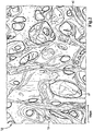
- the Figures 2 and 3 show scanning electron microscope images of the sponge cloth material of the coalescing medium 58 viewed in the flow direction 78 of the fuel.
- the Figure 4 shows the sponge cloth material in a scanning electron microscope image transverse to the flow direction 78. The layer structure of the sponge cloth material can be seen there.
- the sponge cloth material is produced by a viscose process, for example a cellulose xanthate process.
- a viscose process for example a cellulose xanthate process.
- wood is processed into viscose 59 in reactors using solvents.
- Cotton is separated as staple fiber with defined fiber lengths by tearing.
- the cotton fibers 60 can especially in the Figure 2 be recognized.
- the proportion of viscose in the starting material for the sponge cloth material is approximately 70%, and the proportion of cotton is approximately 30%.
- the initially flowable viscose 59 and the cotton fibers 60 are mixed and kneaded together with Glauber's salt and optionally with paint.
- Glauber's salt is used to form pores, it later determines the pore size of the finished sponge cloth material.
- the kneaded mass is placed on a grid, for example painted, by machine, in particular by means of nozzles.
- the mass is then dried on the grid and solidifies.
- the viscose can be regenerated in the solidification process.
- the viscose 59 and the cotton fibers 60 combine to form a unit.
- the initially flowable viscose 59 permeates the cotton fibers 60.
- the viscose 59 "fuses" so to speak between the cotton fibers 60 to form larger, coherent areas in which crystals of Glauber's salt are embedded.
- the viscose 59 acts as a binding material and connects the cotton fibers 60.
- the cotton fibers 60 act as a carrier material and contribute significantly to the strength of the finished sponge cloth material.
- the Glauber's salt is washed out.
- the dissolved crystals of the Glauber's salt are washed out.
- the washed-out mass is dried.
- the finished sponge cloth material has the corresponding pores 61.
- the separating unit 56 has a support basket 62 with a connection section 64, which also has the insertion web 54, and a separating medium 66.
- connection section 64 is approximately disk-shaped with a coaxial opening into which the connecting piece 22 of the cover 16 protrudes.
- the connection section 64 On its outer side facing the cover 16, the connection section 64 has a coaxial connection piece 68.
- the connection piece 68 is bent radially inward by 90 degrees on its free end face.
- a profile ring seal 70 is seated on the radially inner edge of the connection piece 68.
- the connection piece 22 is inserted into the connection piece 68 in such a way that the connection with the profile ring seal 70 is sealed.
- the separating unit 56 is pushed axially through the opening 50 of the connecting end disk 42 with the separating medium 66 first.
- the support basket 62 and the separating medium 66 are located in the interior space delimited by the coalescing medium 58, that is to say also in the interior space 45 of the filter medium 38.
- the separating medium 66 consists of a hydrophobic mesh. It has the shape of a tube coaxial with the filter axis 24. It extends from the connecting end disk 42 to the connecting end disk 40.
- the separating medium 68 is circumferentially closed.
- the circumferential wall of the support basket 62 is constructed like a grid and is permeable to liquid.
- the support cage 62 is open on its end face associated with the connecting piece 22.
- the lower end face of the support cage 62 facing the water collecting space 32 is closed.
- the separating medium 66 rests on the circumferential side of the support cage 62.
- a precipitation gap 74 is located in the interior 45 between the separating medium 66 and the coalescing medium 58.
- the precipitation gap 74 has the shape of an annular space.
- the precipitation gap 74 is delimited radially on the outside by the coalescing medium 58 and radially on the inside by the separating medium 66.
- annular seal 72 is arranged on the radially outer circumferential side of the end disk 40, which ring seal 72 is supported radially on the outside against the radially inner circumferential side of the filter bowl 14. The ring seal 72 seals the inlet space 28 from the water collection space 32.
- additive-containing fuel to be cleaned which may be contaminated with water and dirt particles, is fed from the fuel supply line, indicated by an arrow 76, through the inlet connector 26 to the inlet space 28.
- the fuel flows through the filter medium 38, indicated by arrows 78, from its raw side, radially outside, to its clean side, radially inside.
- the fuel is freed from the particles.
- the filter medium 38 forms a first stage of the three-stage fuel filter 10 for cleaning water separation.
- the fuel with the additive which has been freed from particles, flows through the pores 61 of the coalescing medium 58 from radially outside inwards. Even the smallest water droplets contained in the fuel are caught in the pores 61 of the coalescing medium 58 and combined to form larger water droplets.
- the coalescing medium 58 forms a second stage for cleaning / water separation. If the droplet size is sufficient, the large water droplets are carried away again by the fuel flowing through.
- the fuel with the additive and the large water droplets flow through the openings of the central tube 43 and reach the precipitation gap 74.
- the fuel with the additive flows through the separating medium 66, which forms a third stage for the cleaning / water separation, from radially outside inwards, indicated by arrows 80, and passes upwards into the drainage chamber 20.
- the cleaned and water-free fuel with the Additive leaves the outlet space 20 via the outlet connection 18, indicated by arrows 82, and is fed to the fuel discharge line.
- the large water droplets are retained by the separation medium 66. They sink in the precipitation gap 74 due to their specific weight, which is greater than that of the fuel, downward, indicated by arrows 84, into the water collecting space 32.
- the water drain valve 34 As soon as the water level sensor of the water drain valve 34 detects that the predetermined maximum water level has been reached, the water drain valve 34 is automatically opened. The water leaves the water collecting chamber 32 through the water drain connection 30 and enters the water drain line,
- the cover 16 is removed from the filter bowl 14 in the axial direction.
- the filter element 36 is then pulled out of the filter bowl 14 in the axial direction.
- the filter element 36 is inserted into the filter bowl 14 in the axial direction with the end disk 40 first. Subsequently, the cover 16 with the connection piece 22 first is pushed in the axial direction onto the open side of the filter bowl 14 so that the connection piece 22 protrudes tightly into the profile ring seal 70.
Landscapes
- Engineering & Computer Science (AREA)
- Chemical & Material Sciences (AREA)
- Combustion & Propulsion (AREA)
- Chemical Kinetics & Catalysis (AREA)
- Mechanical Engineering (AREA)
- General Engineering & Computer Science (AREA)
- Filtering Materials (AREA)
Description
- Die Erfindung betrifft ein Koaleszenzelement einer Wasserabscheidevorrichtung, insbesondere eines Kraftstofffilters, für Kraftstoff, insbesondere Dieselkraftstoff, insbesondere mit wenigstens einem Additiv, insbesondere einer Brennkraftmaschine, insbesondere eines Kraftfahrzeugs, das in einem Gehäuse der Wasserabscheidevorrichtung so angeordnet werden kann, dass es wenigstens einen Kraftstoffeinlass des Gehäuses von wenigstens einem Kraftstoffauslass trennt, wobei im Strömungsweg des Kraftstoffs wenigstens ein Koaleszenzmedium zur Abscheidung von im Kraftstoff enthaltenem Wasser angeordnet ist.
- Ferner betrifft die Erfindung eine Wasserabscheidevorrichtung, insbesondere einen Kraftstofffilter, für Kraftstoff, insbesondere Dieselkraftstoff, insbesondere mit wenigstens einem Additiv, insbesondere einer Brennkraftmaschine, insbesondere eines Kraftfahrzeugs, mit einem Gehäuse, welches wenigstens einen Kraftstoffeinlass für zu behandelnden, insbesondere zu reinigenden, Kraftstoff, wenigstens einen Kraftstoffauslass für behandelten Kraftstoff und wenigstens einen Wasserauslass für vom Kraftstoff abgeschiedenes Wasser aufweist, wobei im Strömungsweg des Kraftstoffs wenigstens ein Koaleszenzmedium zur Abscheidung von im Kraftstoff enthaltenem Wasser angeordnet ist.
- Aus der
DE 10 2011 120 641 A1 sind ein Kraftstofffilter für Kraftstoff, insbesondere Dieselkraftstoff, einer Brennkraftmaschine insbesondere eines Kraftfahrzeugs, und ein Filterelement bekannt. Ein Gehäuse des Kraftstofffilters weist wenigstens einen Kraftstoffeinlass für zu reinigenden Kraftstoff, wenigstens einen Kraftstoffauslass für gereinigten Kraftstoff und wenigstens einen Wasserauslass für vom Kraftstoff abgeschiedenes Wasser auf. In dem Gehäuse ist das Filterelement angeordnet, das den Kraftstoffeinlass dicht von dem Kraftstoffauslass trennt. Das Filterelement weist ein als Hohlkörper ausgestaltetes Filtermedium auf, das zur Filtrierung des Kraftstoffs von innen nach außen oder von außen nach innen durchströmbar ist. Im Strömungsweg des Kraftstoffs hinter dem Filtermedium, dieses umgebend oder in dem von ihm begrenzten Innenraum, ist ein als Hohlkörper gestaltetes Koaleszenzmedium zur Abscheidung von im Kraftstoff enthaltenem Wasser angeordnet. Das Koaleszenzmedium umfasst wenigstens eine Lage aus einem zur Koaleszenz von Wasser geeigneten Vlies. Eine Hauptorientierung von Fasern der wenigstens einen Vlieslage verläuft quer zu einem Hauptströmungsweg für das abgeschiedene Wasser stromabwärts des Koaleszenzmediums. - Aus der
US 3 228 527 A und derUS 3 567 619 A sind Kraftstofffiltereinrichtungen mit Wasserabscheidefunktion bekannt - Die
WO 2006/135226 A1 offenbart ein Verfahren zum Trennen einer Flüssigkeitsmischung, die eine polare Flüssigkeit und eine unpolare Flüssigkeit umfasst. - Die
GB 1 123 148 A - Der Erfindung liegt die Aufgabe zugrunde, ein Koaleszenzelement einer Wasserabscheidevorrichtung und einer Wasserabscheidevorrichtung der eingangs genannten Art zu gestalten, bei dem die Abscheidung von im Kraftstoff enthaltenem Wasser weiter verbessert wird.
- Diese Aufgabe wird erfindungsgemäß durch den Gegenstand des Anspruchs 1 gelöst.
- Erfindungsgemäß wird zur Koaleszenz des Wassers wenigstens ein geeignetes schwammartiges Koaleszenzmaterial verwendet. Das wenigstens eine schwammartige Koaleszenzmaterial weist größere, zusammenhängende Bereiche auf. Die Bereiche können miteinander verbunden, insbesondere verschmolzen, sein. In und/oder zwischen den zusammenhängenden Bereichen sind Löcher oder Poren zum Auffangen der Wassertröpfchen und zum Durchtritt des Wassers vorgesehen.
- An dem wenigstens einen Koaleszenzmedium werden auch kleinste Wassertröpfchen, welche im Kraftstoff enthalten sind, vereinigt und in einer anderen Stufe des Koafeszenzelements und/oder der Wasserabscheidevorrichtung zu größeren Wassertropfen vereinigt. Dabei werden die feinen Wassertröpfchen an dem wenigstens einen Koaleszenzmaterial zurückgehalten und vergrößert, bis sie von der Kraftstoffströmung wieder mitgerissen und aus dem wenigstens einen Koaleszenzmedium ausgetragen werden. Die Wassertröpfchen können in oberflächennahen Poren des schwammartigen Koaleszenzmaterials adsorbieren. Dabei gelangen die Wassertröpfchen in die Poren hinein und werden dort gehalten. Nachfolgende Wassertröpfchen können mit den in den Poren gehaltenen Wassertröpfchen zu größeren Wassertropfen koalieren.
- Im Unterschied zum schwammartigen Koaleszenzmaterial können bei Vliesmaterial, welches bei aus dem Stand der Technik bekannten Kraftstofffiltern als Koaleszenzmaterial eingesetzt werden kann, die Wassertröpfchen im Wesentlichen nur an Knotenpunkten von Fasern des Vlieses koalieren. Ferner kann bei Vliesmaterial das Wasser in den Fasern eingelagert werden. Die Fasern können aufquellen und die Durchlassöffnungen zwischen den Fasern entsprechend verkleinert werden. Die Durchströmung des Wassers durch das Vliesmaterial kann verschlechtert werden. Entsprechende Druckdifferenzen zwischen der Einlassseite und der Auslassseite können so unerwünscht vergrößert werden.
- Das schwammartige Koaleszenzmaterial kann extrem gute Saugeigenschaften aufweisen. Es kann daher eine entsprechend hohe Aufnahmekapazität für Wasser haben. Schwammartiges Koaleszenzmaterial kann das etwa 14-fache bis etwa 20-fache seines Trockengewichtes an Wasser aufnehmen. Das schwammartige Koaleszenzmaterial kann aufquellen, wodurch die Aufnahmekapazität für Wasser weiter erhöht werden kann.
- Ferner kann das schwammartige Koaleszenzmaterial größere Abriebfestigkeit aufweisen als Vliesmaterial, so kann die Standzeit des Koaleszenzelements erhöht werden. Außerdem kann das schwammartige Koaleszenzmaterial eine größere Beständigkeit gegen Quetschen oder Pressen als herkömmliches Vliesmaterial aufweisen.
- Das schwammartige Koaleszenzmaterial kann außerdem den Vorteil haben, dass es bei unterschiedlichen Kraftstoffen oder Kraftstoffzusammensetzungen seine Koaleszenzfunktion beibehalten kann. So kann auch bei der Reinigung von Kraftstoffen, insbesondere Dieselkraftstoff, weiche wenigstens ein Additiv enthalten können, die Funktion der Koaleszenz/Wasserabscheidung an dem wenigstens einen schwammartigen Koaleszenzmedium sichergestellt werden.
- Additive sind Zusatzstoffe, die die Eigenschaften des Kraftstoffs verändern, insbesondere verbessern, können. Additive werden in der Regel im verhältnismäßig geringen Mengen dem Kraftstoff zugeführt.
- Die Wassertropfen können stromabwärts des wenigstens einen schwammartigen Koaleszenzmediums insbesondere in einem Ausfällspalt in einer weiteren Stufe des Koaleszenzelements und/oder der Wasserabscheidevorrichtung ausgefällt werden. Sie können aufgrund ihres spezifischen Gewichts nach unten sinken. Dies kann als gravimetrische Wasserabscheidung bezeichnet werden.
- Mit der erfindungsgemäßen Wasserabscheidevorrichtung, insbesondere dem erfindungsgemäßen Koaleszenzelement, können auch Kraftstoffe von Wasser befreit und gegebenenfalls gereinigt werden, deren spezifisches Gewicht größer ist als Wasser, bei denen analog die Wassertropfen räumlich nach oben steigen.
- Zu diesem Zweck kann das Koaleszenzelement und/oder die Wasserabscheidevorrichtung umgedreht angeordnet werden. Entsprechend können der wenigstens eine Kraftstoffeinlass, der wenigstens eine Kraftstoffauslass und gegebenenfalls wenigstens eine Wasserauslass entsprechend angeordnet sein.
- Vorteilhafterweise kann das Wasser insbesondere in wenigstens einem Wassersammelraum gesammelt werden. Der wenigstens eine Wassersammelraum kann vorteilhafterweise mit wenigstens einem Wasserauslass verbunden sein. Über den wenigstens einen Wasserauslass kann das Wasser aus dem wenigstens einen Wassersammelraum abgelassen werden.
- Das Koaleszenzmedium kann vorteilhafterweise eine oder mehrere Lagen aus oder mit schwammartigem Koaleszenzmaterial aufweisen. Jede der Lagen kann in sich und/oder die Lagen untereinander können gleiches oder unterschiedliches Koaleszenzmaterial aufweisen. Zusätzlich zu dem schwammartigen Koaleszenzmaterial kann das wenigstens eine Koaleszenzmedium auch andersartiges Koaleszenzmaterial aufweisen.
- Das Koaleszenzmedium kann vorteilhafterweise zu einem Balg geformt sein. Das Koaleszenzmedium kann vorteilhafterweise gefaltet, gebogen, plissiert und/oder gewickelt sein.
- Das Koaleszenzmaterial ist Schwammtuchmaterial oder weist dieses auf. Bei dem Schwammtuchmaterial kann es sich um ein insbesondere schichtförmiges Gebilde handeln. Das Schwammtuchmaterial kann vorteilhafterweise eine Dicke im trockenen Zustand von etwa 0,4 cm bis 2 cm aufweisen. Das Schwammtuchmaterial kann nach einem Viskoseverfahren, insbesondere einem Cellulosexanthogenat-Verfahren, hergestellt sein.
- Die Erfindung ist nicht beschränkt auf eine Wasserabscheidevorrichtung einer Brennkraftmaschine eines Kraftfahrzeugs. Vielmehr kann sie auch bei andersartigen Brennkraftmaschinen, beispielsweise bei Industriemotoren, eingesetzt werden.
- Statt für Dieselkraftstoff kann die Wasserabscheidevorrichtung auch zur Wasserabscheidung/Reinigung von andersartigem flüssigem Kraftstoff eingesetzt werden.
- Das erfindungsgemäße Koaleszenzelement weist wenigstens ein Filtermedium auf. Das Koaleszenzelement kann auch als Filterelement bezeichnet werden.
- Mit dem wenigstens einen Filtermedium können insbesondere Partikel, welche den Kraftstoff verunreinigen, in einer Stufe des Koaleszenzelements herausgefiltert werden.
- Vorteilhafterweise kann das wenigstens eine Filtermedium als Hohlkörper ausgestaltet sein.
- Vorteilhafterweise kann das Filtermedium zur Filtrierung des Kraftstoffs von innen nach außen oder von außen nach innen durchströmbar sein.
- Das Koaleszenzelement, insbesondere das Filterelement, kann mehrstufig sein. Der Kraftstoff kann zur Reinigung und Wasserabscheidung das wenigstens eine Filtermedium und das wenigstens eine Koaleszenzmedium durchströmen.
- Das wenigstens eine Koaleszenzmedium kann vorteilhafterweise abströmseitig des wenigstens einen Filtermediums angeordnet sein. Auf diese Weise kann das wenigstens eine Koaleszenzmedium mittels dem wenigstens einen Filtermedium vor Verschmutzung geschützt werden. Alternativ oder zusätzlich kann anströmseitig des wenigstens einen Filtermediums wenigstens ein Koaleszenzmedium angeordnet sein,
- Vorteilhafterweise kann das wenigstens eine Koaleszenzmedium in einem Innenraum des wenigstens einen Filtermediums angeordnet sein. Es kann von dem wenigstens einen Filtermedium umgeben sein. Bei einer Durchströmung des Filtermediums von außen nach innen kann das wenigstens eine Koaleszenzmedium so abströmseitig des wenigstens einen Filtermediums angeordnet sein. Bei umgekehrter Durchströmung des Filtermediums kann das wenigstens eine Koaleszenzmedium anströmseitig angeordnet sein. Alternativ oder zusätzlich kann das wenigstens eine Koaleszenzmedium das wenigstens eine Filtermedium umgeben. Entsprechend kann das wenigstens eine Koaleszenzmedium anströmseitig oder abströmseitig des wenigstens einen Filtermediums angeordnet sein,
- Vorteilhafterweise kann das wenigstens eine Koaleszenzmedium das wenigstens eine Filtermedium abströmseitig und/oder anströmseitig wenigstens teilweise abdecken.
- Das wenigstens eine Koaleszenzmedium kann vorteilhafterweise das wenigstens eine Filtermedium anströmseitig und/oder abströmseitig vollständig abdecken. Auf diese Weise muss der Kraftstoff das wenigstens eine Koaleszenzmedium zwangsweise passieren. Alternativ oder zusätzlich kann wenigstens ein Koaleszenzmedium das wenigstens eine Filtermedium anströmseitig und/oder abströmseitig lediglich teilweise abdecken. Auf diese Weise kann der Kraftstoff durch entsprechende Lücken des wenigstens einen Koaleszenzmediums strömen und so das Koaleszenzmedium umgehen.
Das wenigstens eine Filtermedium kann wenigstens eine Partikelfilterlage aufweisen. Es kann vorteilhafterweise Filterpapier, Filtervlies oder ein andersartiges, insbesondere schaumartiges, Filtermaterial aufweisen, welches geeignet ist, Partikel aus dem Kraftstoff, insbesondere Dieselkraftstoff, herauszufiltern. - Vorteilhafterweise kann das wenigstens eine Filtermedium aus einer oder mehreren Lagen bestehen. Das wenigstens eine Filtermedium kann vorteilhafterweise gefaltet, gebogen, plissiert und/oder gewickelt sein. Das Filtermedium, insbesondere der Filtermediumhohlkörper, kann vorteilhafterweise balgartig sein. Das Filtermedium kann vorteilhafterweise sternförmig gefaltet sein. Vorteilhafterweise kann das Filtermedium zickzackförmig gefaltet und umfangsmäßig geschlossen sein. Der Filtermediumhohlkörper kann vorteilhafterweise wenigstens eine Öffnung aufweisen. Durch die Öffnung kann der zu reinigende Kraftstoff in den Innenraum des Filtermediumhohlkörpers hinein oder gereinigter Kraftstoff aus dem Innenraum heraus gelangen. Der Filtermediumhohlkörper kann vorteilhafterweise auf wenigstens einer Stirnseite mit einem Endkörper, insbesondere einer Endscheibe, bevorzugt dicht verbunden sein. Mit dem wenigstens einen Endkörper kann das Filtermedium stabilisiert werden. Wenigstens einer der Endkörper kann eine Öffnung aufweisen. Die Öffnung kann gegebenenfalls mit der Öffnung des Filtermediumhohlkörpers verbunden sein.
- Das wenigstens eine Filtermedium kann vorteilhafterweise die Form eines Hohlzylinders, insbesondere eines Kreiszylinders, aufweisen. Alternativ kann das Filtermedium auch in anderer Form, insbesondere als eine Art Hohlkegel, realisiert sein. Der Filtermediumhohlkörper kann statt mit einer runden Grundfläche auch mit einer andersartigen, insbesondere ovalen oder eckigen, Grundfläche realisiert sein.
Bei einer weiteren vorteilhaften Ausführungsform kann das wenigstens eine Koaleszenzmaterial synthetisch hergestellt sein. Auf diese Weise kann das Koaleszenzmaterial speziell für den Zweck der Zusammenführung von kleinsten Wassertröpfchen bei der Wasserabscheidung bei Kraftstoffen, insbesondere Kraftstoffen mit Additiven, optimiert sein. Ferner kann so die Beständigkeit gegenüber dem Kraftstoff und/oder dem wenigstens einen Additiv erhöht werden. - Bei einer weiteren vorteilhaften Ausführungsform kann das wenigstens eine Koaleszenzmaterial Cellulose, insbesondere Viskose oder regenerierte Cellulose, oder eine Mischung aus Cellulose, insbesondere Viskose oder regenerierter Cellulose, und Baumwolle zumindest aufweisen. Mit Cellulose/Viskose und Mischungen aus Cellulose/Viskose und Baumwolle kann eine Wasserabscheidung bei Kraftstoff verbessert werden. Insbesondere kann die Wasserabscheidung bei Kraftstoffen mit wenigstens einem Additiv weiter verbessert werden.
- Die Cellulose/Viskose kann vorteilhafterweise gegebenenfalls wenigstens ein Bindematerial des wenigstens einen Koaleszenzmaterials wenigstens mit bilden. Die Baumwolle kann vorteilhafterweise gegebenenfalls wenigstens ein Trägermaterial des wenigstens einen Koaleszenzmaterials wenigstens mit bilden. Die Baumwolle kann als "Vernetzer" dienen.
- Vorteilhafterweise kann das wenigstens eine Koaleszenzmaterial aus einem Anteil von etwa 70 % Holz als Ausgangsmaterial hergestellt sein. Das Holz kann vorteilhafterweise insbesondere in Reaktoren mittels Lösemitteln zu Viskose verarbeitet werden. Vorteilhafterweise werden dabei Fasern nicht zerstört.
- Bei einer weiteren vorteilhaften Ausführungsform kann das wenigstens eine Koaleszenzmaterial Fasern, insbesondere Cellulosefasern/Viskose und/oder Baumwollfasern, aufweisen. Das Koaleszenzmaterial kann dabei eine Mischung der entsprechenden Fasern aufweisen. Die Fasern können das wenigstens eine Koaleszenzmaterial mechanisch stabilisieren. Die Fasern können gegebenenfalls das wenigstens eine Trägermaterial mit bilden. Sie können als Stapelfasern dienen.
- Vorteilhafterweise können die Fasern, insbesondere die Baumwollfasern, Längen in der Größenordnung von etwa 20 mm aufweisen.
- Vorteilhafterweise kann das Ausgangsmaterial für das wenigstens eine Koaleszenzmaterial einen Anteil von 30 % Baumwolle aufweisen.
- Vorteilhafterweise kann zur Herstellung des Koaleszenzmaterials Baumwolle als Stapelfaser insbesondere durch Reißen vereinzelt werden. Anschließend kann die Baumwolle mit Natronlauge befeuchtet werden.
- Bei einer weiteren vorteilhaften Ausführungsform kann das wenigstens eine Koaleszenzmaterial aus einer Masse hergestellt sein, die einen Porenbildner, insbesondere Glaubersalz, enthält, wobei der Porenbildner beim fertigen Koaleszenzmaterial entfernt sein kann.
- Vorteilhafterweise kann zur Herstellung des wenigstens einen Koaleszenzmaterials wenigstens ein Bindematerial, insbesondere Viskose, und wenigstens einen Trägermaterial, insbesondere Baumwolle, insbesondere in Form von Fasern, zusammen mit einem Porenbildner, insbesondere Salzkristalle, vorzugsweise Glaubersalz, und gegebenenfalls Farbstoffen vermischt und verknetet werden. Die Masse kann in dem Knetprozess dreidimensional vernetzt werden. Dabei kann ermöglicht werden, dass keine künstliche Faserbildung und keine mechanische zusätzliche Verfestigung entstehen. Die verknetete Masse kann eine verhältnismäßig hohe Viskosität aufweisen.
- Die verknetete Masse kann insbesondere maschinell auf eine Trägerbahn, insbesondere ein Gitter, gestrichen werden. Die Masse kann dabei insbesondere auf die Trägerbahn insbesondere mittels Düsen abgelegt werden. Die Masse kann auf die Trägerbahn gepresst werden.
- Die Masse kann insbesondere auf der Trägerbahn getrocknet werden. Dabei wird die Masse fest. Der eingearbeitete Porenbildner dient der Porenbildung. Der Porenbildner gibt dabei die Porengröße vor. In dem Verfestigungsprozess kann die Cellulose, insbesondere Viskose, regeneriert werden. Die Cellulose/Viskose und die Baumwolle können sich zu einer Einheit verbinden.
- Der Porenbildner, insbesondere die Kristalle des Glaubersalzes, können, insbesondere mit Wasser und/oder Säure, ausgewaschen werden. Das fertigte schwammartige Koaleszenzmaterial weist die entsprechenden Poren auf. Dabei kann das wenigstens eine Trägermaterial eine Festigkeit und/oder Vernetzung vorgeben. Das wenigstens eine Bindematerial kann flächige/zusammenhängende Bereiche bilden.
- Im Unterschied zum schwammartigen Koaleszenzmaterial werden bei der Herstellung von bekanntem Vliesmaterial verschiedene Einzelfaserarten vermischt abgelegt und verfestigt. Dies kann mittels einem Wasserstrahlverfahren oder Vernadelung geschehen. Viskosefasern werden dazu separat hergestellt, also in Lösung gebracht und mit Düsen gesponnen, und als Fasern zugegeben.
- Bei einer weiteren vorteilhaften Ausführungsform kann das wenigstens eine Koaleszenzmaterial wenigstens ein Trägermaterial umfassen, welches mit wenigstens einem Bindematerial durchwirkt sein kann. Auf diese Weise kann das wenigstens eine Trägermaterial mit dem wenigstens einen Bindematerial einen Verbund eingehen oder bilden. So können größere, zusammenhängende Bereiche mit dazwischenliegenden Löchern realisiert werden. Die Bereiche können mit dem wenigstens einen Bindematerial verbunden sein.
- Das wenigstens eine Trägermaterial, insbesondere Baumwolle, kann als "Vernetzer" dienen. Es kann zur Festigkeit des wenigstens einen Koaleszenzmaterials beitragen, insbesondere diese im Wesentlichen bewirken,
- Vorteilhafterweise kann das wenigstens eine Koaleszenzmaterial als Schichtstruktur realisiert sein. Auf diese Weise kann eine von dem Kraftstoff durchströmbare Dicke des Koaleszenzmediums variiert werden.
- Vorteilhafterweise kann das wenigstens eine Trägermaterial wenigstens einen synthetischen Anteil und/oder wenigstens einen nichtsynthetischen Anteil aufweisen.
- Vorteilhafterweise kann das wenigstens eine Trägermaterial wenigstens ein Textil, ein Gewebe, ein nichtgewebtes (nonwoven) Material, ein Netz, ein Gitter, ein Geflecht, ein Gestrick, ein Gewirk, ein Nähgewirk, ein Vlies, ein Filz und/oder ein anderes Fasern aufweisendes oder faserfreies Material aufweisen.
- Vorteilhafterweise kann das wenigstens eine Trägermaterial Fasern, insbesondere Baumwollfasern und/oder Cellulosefasern und/oder Viskosefasern, aufweisen. Das wenigstens eine Trägermaterial kann mit dem wenigstens einen Bindematerial verbunden, umgeben oder in einer anderen Weise insbesondere nicht faserig oder textilartig durchwirkt sein.
- Das wenigstens eine Bindematerial kann vorteilhafterweise zur Herstellung des wenigstens einen Koaleszenzmaterials zunächst fließfähig sein. Auf diese Weise kann das wenigstens eine Bindematerial das wenigstens eine Trägermaterial durchwirken. Das Bindematerial kann etwaige Trägerstrukturen des Trägermaterials umfließen und/oder einbetten/einhüllen.
- Vorteilhafterweise kann das wenigstens eine Bindematerial zur Herstellung des wenigstens einen Koaleszenzmaterials nicht textilartig verarbeitet, insbesondere gesponnen, gewebt, geflochten, genäht, gestrickt, gewirkt oder dergleichen, sein.
- Vorteilhafterweise kann das wenigstens eine Bindematerial wenigstens Viskose aufweisen. Das wenigstens eine Bindematerial kann vorteilhafterweise frei von Fasern sein. Auf diese Weise kann die Fließfähigkeit verbessert werden. Ferner kann so die Verbundfähigkeit mit dem Trägermaterial verbessert werden. Alternativ kann das wenigstens eine Bindematerial Fasern enthalten. Es kann so zur Festigkeit des wenigstens einen Koaleszenzmaterials beitragen.
- Das wenigstens eine Koaleszenzmedium ist als Hohlkörper gestaltet Der Hohlkörper des wenigstens einen Koaleszenzmediums kann einfach gegebenenfalls in dem Innenraum des Hohlkörpers des wenigstens einen Filtermediums angeordnet werden. Alternativ kann der wenigstens eine Filtermediumhohlkörper in dem Hohlkörper des wenigstens einen Koaleszenzmediums angeordnet werden. Die entsprechenden Umfangsseiten der Hohlkörper können dabei aneinander anliegen. Die Umfangsseiten der Hohlkörper können sich gegenseitig abstützen. Alternativ können die Umfangsseiten der Hohlkörper zueinander beabstandet sein.
- Vorteilhafterweise können der Hohlkörper des wenigstens einen Koaleszenzmediums und gegebenenfalls der Hohlkörper des wenigstens einen Filtermediums eine ähnliche Form aufweisen. Sie können vorteilhafterweise zueinander passende Größen aufweisen. Auf diese Weise können die Hohlkörper platzsparend ineinander angeordnet werden.
- Der Hohlkörper des wenigstens einen Koaleszenzmediums kann vorteilhafterweise eine zylindrische oder konische Form aufweisen. Der Querschnitt des Hohlkörpers kann vorteilhafterweise rund, oval oder eckig sein. Der Hohlkörper kann vorteilhafterweise umfangsmäßig geschlossen sein. Der Hohlkörper kann vorteilhafterweise wenigstens an einer seiner Stirnseiten offen sein. Dort kann das abgeschiedene Wasser und/oder der Kraftstoff aus einem Innenraum des Hohlkörpers heraus oder mit Wasser belasteter Kraftstoff in den Innenraum des Hohlkörpers hinein gelangen.
- In einem Innenraum des Koaleszenzelements, insbesondere eines Koaleszenzmedium-Hohlkörpers und/oder gegebenenfalls eines Filtermediumhohlkörpers, oder dieses umgebend kann wenigstens ein Stützkörper, insbesondere ein Stützrohr, angeordnet sein. An dem wenigstens einen Stützkörper kann sich das wenigstens eine Koaleszenzmedium und/oder gegebenenfalls wenigstens ein Filtermedium abstützen.
- Bei der erfindungsgemäßen Ausführungsform ist im Strömungsweg des Kraftstoffs hinter dem wenigstens einen Koaleszenzmedium, dieses umgebend oder in dem von ihm begrenzten Innenraum, wenigstens ein als Hohlkörper gestaltetes hydrophobes, kraftstoffdurchlassiges Trennmedium zur Abscheidung von im Kraftstoff enthaltenem Wasser angeordnet, derart, dass zwischen dem wenigstens einen Koaleszenzmedium und dem wenigstens einen Trennmedium wenigstens ein Ausfällspalt für abgeschiedenes Wasser realisiert ist. An dem wenigstens einen Trennmedium können Wassertropfen, welche im Kraftstoff enthalten sind, zurückgehalten werden. Auf diese Weise kann die Wasserabscheidung verbessert werden. Vorteilhafterweise können die Wassertropfen, welche mit dem wenigstens einen Koaleszenzmedium vereinigt wurden, besser abgeschieden werden.
- Vorteilhafterweise kann das wenigstens eine Trennmedium den wenigstens einen Ausfällspalt auf der dem wenigstens einen Koaleszenzmedium gegenüberliegenden Seite begrenzen. Die mit dem wenigstens einen Koaleszenzmedium vereinigten großen Wassertropfen können im Strömungsweg des Kraftstoffs hinter dem wenigstens einen Koaleszenzmedium in dem wenigstens einen Ausfällspalt ausgefällt werden. Sie können abhängig vom spezifischen Gewicht des Kraftstoffs nach unten sinken oder nach oben steigen.
- Vorteilhafterweise kann das wenigstens eine Trennmedium siebartig sein. Ein siebartiges, insbesondere gewebtes Trennmedium hat den Vorteil, dass die Wassertropfen an den Siebfasern gehalten werden und insbesondere nach unten abtropfen beziehungsweise nach oben steigen können. An einem siebartigen Trennmedium kann das Wasser optimal zurückgehalten werden. Die Maschenöffnungen eines siebartigen Gewebes können einfach und definiert vorgegeben werden. Es kann optimal durchlässig für den Kraftstoff ausgestaltet sein. Mit einer siebartigen Struktur kann einfach der Druckverlust an dem wenigstens einen Trennmedium minimiert werden.
- Das wenigstens eine Trennmedium kann vorteilhafterweise eine ähnliche Form aufweisen wie der Hohlkörper des wenigstens einen Filtermediums und/oder gegebenenfalls der Hohlkörper des wenigstens einen Koaleszenzmediums. Auf diese Weise können die Hohlkörper und das Trennmedium platzsparend ineinander angeordnet werden.
- Das wenigstens eine Trennmedium kann vorteilhafterweise eine zylindrische oder konische Form aufweisen. Der Querschnitt des wenigstens einen Trennmediums kann vorteilhafterweise rund, oval oder eckig sein. Das wenigstens eine Trennmedium kann vorteilhafterweise umfangsmäßig geschlossen sein. Das wenigstens eine Trennmedium kann vorteilhafterweise wenigstens an einer seiner Stirnseiten offen sein. Dort kann der von Wasser befreite Kraftstoff aus einem Innenraum des wenigstens einen Trennmediums heraus gelangen oder der mit Wasser belastete Kraftstoff zur Wasserabscheidung in den Innenraum geleitet werden.
- Vorteilhafterweise kann der wenigstens eine Ausfällspalt gegebenenfalls mit dem wenigstens einen Wassersammelraum und/oder dem wenigstens einen Wasserauslass des Gehäuses des Kraftstofffilters verbunden sein.
- Bei einer weiteren vorteilhaften Ausführungsform können das wenigstens eine Koaleszenzmedium, das wenigstens eine Filtermedium und/oder das wenigstens eine Trennmedium koaxial angeordnet sein. Eine koaxiale Anordnung ist platzsparend, Ferner kann in einer koaxialen Anordnung ein Strömungsverlauf des Kraftstoffs von radial außen nach radial innen oder radial innen nach radial außen einfach optimiert werden. Die Grundflächen des wenigstens einen Koaleszenzmediums, des wenigstens einen Filtermediums und/oder des wenigstens einen Trennmediums können dabei ähnlich sein. Die Grundflächen können aber auch unterschiedlich sein. Sie können insbesondere rund, oval oder eckig sein.
- Das wenigstens eine Koaleszenzmedium, das wenigstens eine Filtermedium und/oder das wenigstens eine Trennmedium können auch anders als koaxial angeordnet sein.
- Bei einer weiteren vorteilhaften Ausführungsform kann das Koaleszenzelement ein Rundfilterelement sein. Es kann sich dabei vorteilhafterweise um ein Rundfilterelement mit einem runden Querschnitt, ein ovales Rundfilterelement mit einem ovalen Querschnitt, ein konisches Rundfilterelement, welches eine kegelartige Form aufweist, oder ein konisch-ovales Rundfilterelement handeln. Rundfilterelemente zeichnen sich durch ein bezüglich einer Elementachse umfangsmäßig geschlossenes Filtermedium aus. An wenigstens einer Stirnseite kann das Filtermedium mit einem Endkörper, insbesondere einer Endscheibe, bevorzugt dicht verbunden sein. Wenigstens einer der Endkörper kann einen zentralen Durchlass für den Kraftstoff aufweisen. Der Kraftstoff kann das Rundfilterelement bezüglich der Elementachse von radial außen nach radial innen oder umgekehrt durchströmen.
- Rundfilterelemente können platzsparend aufgebaut werden. Mit Rundfilterelementen kann ein optimales Verhältnis von Filter-/Abscheidefläche zum Bauraum realisiert werden.
- Die Aufgabe wird erfindungsgemäß ferner durch die Wasserabscheidevorrichtung nach Anspruch 8 gelöst
- Die im Zusammenhang mit dem erfindungsgemäßen Koaleszenzelement und dessen vorteilhafte Ausführungsformen aufgezählten Vorteile und Merkmale gelten für die erfindungsgemaße Wasserabscheidevorrichtung und deren vorteilhafte Ausführungsformen entsprechend und umgekehrt.
- Vorteilhafterweise kann das wenigstens eine Koaleszenzmedium Bestandteil eines Koaleszenzelements, insbesondere eines erfindungsgemaßen Koaleszenzelements, sein.
- Bei einer vorteilhaften Ausführungsform kann in dem Gehäuse wenigstens ein Filtermedium angeordnet sein.
- Vorteilhafterweise kann das wenigstens eine Filtermedium Bestandteil eines Koaleszenzelements, insbesondere eines erfindungsgemäßen Koaleszenzelements, sein. Das Koaleszenzelement kann in diesem Fall auch als Filterelement bezeichnet werden. Entsprechend kann die Wasserabscheidevorrichtung auch als Kraftstofffilter bezeichnet werden.
- Vorteilhafterweise kann das wenigstens eine Filtermedium den wenigstens einen Kraftstoffeinlass von dem wenigstens einen Kraftstoffauslass trennen. Vorteilhafterweise kann das wenigstens eine Filtermedium als Hohlkörper ausgestaltet sein.
- Vorteilhafterweise kann das wenigstens eine Filtermedium zur Filtrierung des Kraftstoffs von innen nach außen oder von außen nach innen durchströmbar sein.
- Vorteilhafterweise kann das wenigstens eine Koaleszenzmedium im Strömungsweg hinter und/oder vor dem wenigstens einen Filtermedium angeordnet sein.
- Vorteilhafterweise kann das wenigstens eine Koaleszenzmedium das wenigstens eine Filtermedium abströmseitig und/oder anströmseitig wenigstens teilweise abdecken.
- Bei einer weiteren vorteilhaften Ausführungsform kann das Gehäuse öffenbar sein und das wenigstens eine Koaleszenzmedium, insbesondere ein Koaleszenzelement, kann austauschbar im Gehäuse angeordnet sein. Das wenigstens eine Koaleszenzmedium, insbesondere das wenigstens eine Koaleszenzelement, kann so einfach zum Austausch oder zu Wartungszwecken aus dem Gehäuse entfernt werden.
- Alternativ kann das Koaleszenzmedium/Koaleszenzelement auch fest in dem Gehäuse angeordnet sein. In diesem Fall ist es nicht erforderlich, dass das Gehäuse öffenbar ist.
- Weitere Vorteile, Merkmale und Einzelheiten der Erfindung ergeben sich aus der nachfolgenden Beschreibung, in der ein Ausführungsbeispiel der Erfindung anhand der Zeichnung näher erläutert wird. Der Fachmann wird die in der Zeichnung, der Beschreibung und den Ansprüchen in Kombination offenbarten Merkmale zweckmäßigerweise auch einzeln betrachten und zu sinnvollen weiteren Kombinationen zusammenfassen. Es zeigen
- Figur 1
- einen schematischen Längsschnitt eines Kraftstofffilters mit einem austauschbaren, dreistufigen Filterelement, das ein Koaleszenzmedium aus einem Schwammtuchmaterial aufweist;
- Figuren 2 und 3
- schematische Darstellungen des Schwammtuchmaterials des Kraftstofffilters aus der
Figur 1 , in Durchströmrichtung des Kraftstoffs betrachtet; - Figur 4
- eine schematische Darstellung des Schwammtuchmaterials des Kraftstofffilters aus der
Figur 1 , quer zur Durchströmrichtung des Kraftstoffs betrachtet; - Figur 5
- eine schematische Darstellung eines aus dem Stand der Technik bekannten Koaleszenzmediums aus einem Vlies, in Durchströmrichtung des Kraftstoffs betrachtet.
- In den Figuren sind gleiche Bauteile mit gleichen Bezugszeichen versehen.
- In der
Figur 1 ist im Längsschnitt ein Kraftstofffilter 10 eines Kraftstoffsystems einer Brennkraftmaschine eines Kraftfahrzeugs gezeigt. Der Kraftstofffilter 10 dient zur Reinigung des für den Betrieb der Brennkraftmaschine verwendeten Kraftstoffs, beispielsweise Dieselkraftstoff. Der Kraftstoff enthält ein Additiv zur Verbesserung der Eigenschaften des Kraftstoffs. Ferner dient der Kraftstofffilter 10 zur Abscheidung von in dem Kraftstoff enthaltenem Wasser. - Der Kraftstofffilter 10 verfügt über ein zweiteiliges Gehäuse 12 mit einem becherförmigen Filtertopf 14 und einem Filterdeckel 16, der trennbar auf dem Filtertopf 14 angeordnet ist. Zwischen dem Filtertopf 14 und dem Filterdeckel 16 ist eine Ringdichtung 17 angeordnet.
- In dem Deckel 16 ist etwa zentral ein Auslassstutzen 18 für den gereinigten Kraftstoff angeordnet, weicher außerhalb des Gehäuses 12 mit einer in der
Figur 1 nicht gezeigten Kraftstoffableitung verbunden ist. Im Inneren des Gehäuses 12 ist der Auslassstutzen 18 mit einem Ablaufraum 20 in einem Innenraum eines Verbindungsstutzens 22 verbunden. Der Verbindungsstutzen 22 erstreckt sich auf der dem Inneren des Gehäuses 12 zugewandten Seite des Deckels 16 koaxial zu einer Filterachse 24. - In der normalen Einbaulage unter normalen Betriebsbedingungen der Brennkraftmaschine verläuft die Filterachse 24, wie in der
Figur 1 gezeigt, räumlich vertikal. "Axial", "radial", "koaxial" und "umfangsmäßig" beziehen sich im Folgenden, wenn nicht anders angegeben, auf die Filterachse 24. - Radial außerhalb des Verbindungsstutzens 22 weist der Deckel 16 einen Einlassstutzen 26 für den zu reinigenden Kraftstoff auf, der mit einem Zulaufraum 28 im Gehäuse 12 verbunden ist. Außerhalb des Gehäuses 12 ist der Einlassstutzen 26 mit einer in der
Figur 1 nicht gezeigten Kraftstoffeuleitung für den Kraftstoff verbunden. - Im Boden des Filtertopfs 14 ist ein Wasserablaufstutzen 30 koaxial zur Filterachse 24 angeordnet. Der Wasserablaufstutzen 30 ist mit einem Wassersammelraum 32 unten im Gehäuse 12 verbunden. Außerhalb des Gehäuses 12 ist der Wasserablaufstutzen 30 mit einer nicht gezeigten Wasserablassleitung verbunden, über die von dem Kraftstoff abgeschiedenes Wasser aus dem Gehäuse 12 abgeleitet werden kann. In dem Wasserablaufstutzen 30 ist ein Wasserablassventil 34 mit einem Wasserstandsensor angeordnet. Im Ruhezustand ist das Wasserablassventil 34 geschlossen, sodass keine Flüssigkeit aus dem Wassersammelraum 32 durch den Wasserablaufstutzen 30 aus dem Gehäuse 12 entweichen kann. Bei Erreichen eines vorgegebenen maximalen Wasserstandes im Wassersammelraum 32 öffnet das Wasserablassventil 34 automatisch, sodass das abgeschiedene Wasser über den Wasserablaufstutzen 30 abgelassen werden kann.
- In dem Gehäuse 12 ist ein austauschbares Filterelement 36 angeordnet. Das Filterelement 36 ist als Rundfilterelement ausgestaltet. Das Filterelement 36 trennt den Einlassstutzen 26 dicht von dem Auslassstutzen 18. Das Filterelement 36 umfasst ein sternförmig gefaltetes Filtermedium 38, mit dem insbesondere Partikel aus dem zu reinigenden Kraftstoff heraus filtriert werden. Das Filtermedium 38 hat insgesamt die Form eines koaxialen Kreiszylindermantels. An einer dem Boden des Filtertopfs 14 zugewandten unteren Stirnseite ist das Filtermedium 38 dicht mit einer Abschlussendscheibe 40 verbunden. An seiner gegenüberliegenden, dem Deckel 16 zugewandten oberen Stirnseite ist das Filtermedium 38 dicht mit einer Anschlussendscheibe 42 verbunden. Zwischen der Anschlussendscheibe 42 und der Abschlussendscheibe 40 erstreckt sich in einem Innenraum 45 des Filtermediums 38 koaxial ein skelettartiges, fluiddurchlässiges Mittelrohr 43, welches die beiden Endscheiben 40 und 42 miteinander verbindet.
- Die Abschlussendscheibe 40 weist eine koaxiale Öffnung 44 auf. Die Öffnung 44 ist von dem Mittelrohr 43 umgeben. Die Öffnung 44 verbindet den Innenraum 45 mit dem Wassersammelraum 32. Auf der dem Boden des Filtertopfs 14 zugewandten Außenseite verfügt die Abschlussendscheibe 40 über beispielhaft vier Stützstege 46, die sich gleichmäßig verteilt entlang eines gedachten koaxialen Kreiszylindermantels erstrecken. Es können auch mehr oder weniger als vier Stützstege 46 vorgesehen sein. Der gedachte Kreiszylindermantel umgibt die Öffnung 44 und den Wasserablaufstutzen 30. Mit den Stützstegen 46 wird das Filterelement 36 gegen den Boden des Filtertopfs 14 abgestützt. Zwischen den Stützstegen 46 befinden sich Verbindungsöffnungen 48, über die sich Wasser im Wassersammelraum 32 auch radial außerhalb der Stützstege 46 verteilen kann.
- Die Anschlussendscheibe 42 weist eine koaxiale Öffnung 50 auf. Die Öffnung 50 ist von zwei koaxialen Vorsprüngen umgeben, die sich an der Außenseite der Anschlussendscheibe 42 in axialer Richtung erstrecken. Die beiden Vorsprünge begrenzen eine Aufnahmenut 52 für einen ringartigen Einstecksteg 54 einer Trenneinheit 56 des Filterelements 36.
- Zwischen der radial inneren Umfangsseite des Filtermediums 38 und dem Mittelrohr 43 befindet sich ein koaxiales Koaleszenzmedium 58. Das Koaleszenzmedium 58 besteht aus einer Lage eines Schwammtuchmaterials. Das Koaleszenzmedium 58 ist umfangsmäßig geschlossen und erstreckt sich zwischen der Anschlussendscheibe 42 und der Abschlussendscheibe 40. Das Koaleszenzmedium 58 dient der Zusammenführung auch von kleinsten im Kraftstoff enthaltenen Wassertröpfchen zu größeren Wassertropfen. Aufgrund seiner Koaleszenzfunktion und/oder seiner Wasserabscheidefunktion kann das Filterelement 36 auch als Koaleszenzelement bezeichnet werden. Entsprechend kann der Kraftstofffilter 10 als Wasserabscheidevorrichtung für Kraftstoff bezeichnet werden.
- Bei dem Schwammtuchmaterial handelt es sich um ein insbesondere schichtförmiges Gebilde mit einer Dicke im trockenen Zustand von etwa 0,4 cm bis 2 cm. Die
Figuren 2 und3 zeigen Rasterelektronenmikroskop-Aufnahmen des Schwammtuchmaterials des Koaleszenzmediums 58 in Durchströmrichtung 78 des Kraftstoffs betrachtet. DieFigur 4 zeigt das Schwammtuchmaterial in einer Rasterelektronenmikroskop-Aufnahme quer zur Durchströmrichtung 78. Dort ist die Schichtstruktur des Schwammtuchmaterials erkennbar. - Das Schwammtuchmaterial ist nach einem Viskoseverfahren, beispielsweise einem Cellulosexanthogenat-Verfahren, hergestellt. Hierzu wird Holz in Reaktoren mittels Lösemitteln zu Viskose 59 verarbeitet. Baumwolle wird als Stapelfaser mit definierten Faserlängen durch Reißen vereinzelt Die Baumwolifasern 60 können insbesondere in der
Figur 2 erkannt werden. Der Anteil von Viskose an dem Ausgangsmaterial für das Schwammtuchmaterial beträgt etwa 70 %, der Anteil an Baumwolle etwa 30 %. - Dann werden die zunächst fließfähige Viskose 59 und die Baumwollfasern 60 zusammen mit Glaubersalz und optional mit Farbe vermischt und verknetet. Das eingearbeitete Glaubersalz dient der Porenbildung, Es gibt später die Porengröße des fertigen Schwammtuchmaterials vor.
- Die verknetete Masse wird beispielsweise maschinell, insbesondere mittels Düsen, auf ein Gitter gelegt, beispielsweise gestrichen.
- Anschließend wird die Masse auf dem Gitter getrocknet und verfestigt sich. In dem Verfestigungsprozess kann die Viskose regeneriert werden. Die Viskose 59 und die Baumwollfasern 60 verbinden sich zu einer Einheit. Dabei durchwirkt die zunächst fließfähige Viskose 59 die Baumwollfasern 60. Die Viskose 59 "verschmilzt" sozusagen zwischen dem Baumwollfasern 60 zu größeren, zusammenhängenden Bereichen, in welchen Kristalle des Glaubersalzes eingebettet sind. Die Viskose 59 wirkt als Bindematerial und verbindet die Baumwollfasern 60. Die Baumwollfasern 60 wirken als Trägermaterial und tragen wesentlich zur Festigkeit des fertigen Schwammtuchmaterials bei.
- Es erfolgt das Auswaschen des Glaubersalzes. Die gelösten Kristalle des Glaubersalzes werden ausgewaschen. Die ausgewaschene Masse wird getrocknet. Das fertigte Schwammtuchmaterial weist die entsprechenden Poren 61 auf.
- In der
Figur 5 ist zur Unterscheidung ein aus dem Stand der Technik bekanntes Koaleszenzmaterial aus einem Vliesmaterial aus Baumwolle, Viskose und Polyesterfasern (PES) gezeigt. Es ist deutlich erkennbar, dass die dortigen Fasern nicht mittels eines Bindematerials, wie dies erfindungsgemäß der Fall ist, verbunden sind. - Die Trenneinheit 56 verfügt über einen Stützkorb 62 mit einem Anschlussabschnitt 64, welcher auch den Einstecksteg 54 aufweist, und ein Trennmedium 66.
- Der Anschlussabschnitt 64 ist etwa scheibenförmig mit einer koaxialen Öffnung, in die der Verbindungsstutzen 22 des Deckels 16 hinein ragt. Auf seiner dem Deckel 16 zugewandten Außenseite verfügt der Anschlussabschnitt 64 über einen koaxialen Anschlussstutzen 68. Der Anschlussstutzen 68 ist an seiner freien Stirnseite um 90 Grad radial nach innen gebogen. Auf dem radial inneren Rand des Anschlussstutzens 68 sitzt eine Profilringdichtung 70. In den Anschlussstutzen 68 ist der Verbindungsstutzen 22 so eingesteckt, dass die Verbindung mit der Profilringdichtung 70 abgedichtet ist.
- Die Trenneinheit 56 ist mit dem Trennmedium 66 voran axial durch die Öffnung 50 der Anschlussendscheibe 42 gesteckt. Der Stützkorb 62 und das Trennmedium 66 befinden sich in dem vom Koaleszenzmedium 58 begrenzten Innenraum, also auch im Innenraum 45 des Filtermediums 38.
- Das Trennmedium 66 besteht aus einem hydrophoben Siebgewebe. Es hat die Form eines zur Filterachse 24 koaxialen Rohres. Es erstreckt sich von der Anschlussendscheibe 42 bis zur Abschlussendscheibe 40. Das Trennmedium 68 ist umfangsmäßig geschlossen.
- Die Umfangswand des Stützkorbs 62 ist gitterartig aufgebaut und flüssigkeitsdurchlässig. Auf seiner der Verbindungsstutzen 22 zugeordneten Stirnseite ist der Stützkorb 62 offen. Die dem Wassersammelraum 32 zugewandte untere Stirnseite des Stützkorbs 62 ist geschlossen. Das Trennmedium 66 liegt an der Umfangsseite des Stützkorbs 62 an.
- Zwischen dem Trennmedium 66 und dem Koaleszenzmedium 58 befindet sich im Innenraum 45 ein Ausfällspalt 74. Der Ausfällspalt 74 hat die Form eines Ringraums. Der Ausfällspalt 74 ist radial außen durch das Koaleszenzmedium 58 und radial innen durch das Trennmedium 66 begrenzt.
- An der radial äußeren Umfangsseite der Abschlussendscheibe 40 ist außerdem eine Ringdichtung 72 angeordnet, welche sich radial außen gegen die radial innere Umfangsseite des Filtertopfs 14 abstützt. Die Ringdichtung 72 dichtet den Zulaufraum 28 gegen den Wassersammelraum 32 ab.
- Beim Betrieb des Kraftstofffilters 10 wird zu reinigender, Additiv enthaltender Kraftstoff, der mit Wasser und Schmutzpartikeln belastet sein kann, aus der Kraftstoffzuleitung, angedeutet durch einen Pfeil 76, durch den Einlassstutzen 26 dem Zulaufraum 28 zugeführt.
- Der Kraftstoff durchströmt das Filtermedium 38, angedeutet durch Pfeile 78, von dessen Rohseite radial außen zu seiner Reinseite radial innen. Dabei wird der Kraftstoff von den Partikeln befreit. Das Filtermedium 38 bildet eine erste Stufe des insgesamt dreistufigen Kraftstofffilters 10 für die ReinigungWasserabscheidung.
- Auf der Reinseite durchströmt der von Partikeln befreite Kraftstoff mit dem Additiv die Poren 61 des Koaleszenzmediums 58 von radial außen nach innen. Dabei werden im Kraftstoff enthaltene, auch kleinste Wassertröpfen in den Poren 61 des Koaleszenzmediums 58 eingefangen und zu größeren Wassertropfen vereinigt. Das Koaleszenzmedium 58 bildet eine zweite Stufe für die Reinigung/Wasserabscheidung. Wenn die Tropfengröße ausreichend ist, werden die großen Wassertropfen vom durchströmenden Kraftstoff wieder mitgerissen.
- Der Kraftstoff mit dem Additiv und die großen Wassertropfen durchströmen die Öffnungen des Mittelrohrs 43 und gelangen in den Ausfällspalt 74.
- Der Kraftstoff mit dem Additiv durchströmt das Trennmedium 66, welches eine dritte Stufe für die Reinigung/Wasserabscheidung bildet, von radial außen nach innen, angedeutet durch Pfeile 80, und gelangt nach oben in den Ablaufraum 20. Der gereinigte und von Wasser befreite Kraftstoff mit dem Additiv verlässt den Ablaufraum 20 über den Auslassstutzen 18, angedeutet durch Pfeile 82, und wird der Kraftstoffableitung zugeführt.
- Die großen Wassertropfen hingegen werden durch das Trennmedium 66 zurückgehalten. Sie sinken im Ausfällspalt 74 aufgrund ihres im Vergleich zum Kraftstoff größeren spezifischen Gewichts nach unten, angedeutet durch Pfeile 84, in den Wassersammelraum 32.
- Sobald der Wasserstandsensor des Wasserablassventils 34 das Erreichen des vorgegebenen Maximalwasserstands erfasst, wird das Wasserablassventil 34 automatisch geöffnet Das Wasser verlässt den Wassersammelraum 32 durch den Wasserablaufstutzen 30 und gelangt in die Wasserablaufleitung,
- Zu Wartungszwecken, beispielsweise zum Austausch oder zur Reinigung des Filterelements 36, wird der Deckel 16 in axialer Richtung von dem Filtertopf 14 entfernt. Das Filterelement 36 wird dann in axialer Richtung aus dem Filtertopf 14 heraus gezogen.
- Zum Einbau wird das Filterelement 36 mit der Abschlussendscheibe 40 voran in axialer Richtung in den Filtertopf 14 gesteckt. Anschließend wird der Deckel 16 mit dem Verbindungsstutzen 22 voran in axialer Richtung auf die offene Seite des Filtertopfs 14 gesteckt, so dass der Verbindungsstutzen 22 dicht in die Profilringdichtung 70 ragt.
Claims (9)
- Koaleszenzelement (36) einer Wasserabscheidevorrichtung, insbesondere eines Kraftstofffilters (10), für Kraftstoff, insbesondere Dieselkraftstoff, insbesondere mit wenigstens einem Additiv, insbesondere einer Brennkraftmaschine, insbesondere eines Kraftfahrzeugs, das in einem Gehäuse (12) der Wasserabscheidevorrichtung (10) so angeordnet werden kann, dass es wenigstens einen Kraftstoffeinlass (26) des Gehäuses (12) von wenigstens einem Kraftstoffauslass (18) trennt, wobei im Strömungsweg (78) des Kraftstoffs wenigstens ein Filtermedium (38) und wenigstens ein als Hohlkörper gestaltetes Koaleszenzmedium (58) zur Abscheidung von im Kraftstoff enthaltenem Wasser angeordnet ist, und wobei im Strömungsweg (78) des Kraftstoffs hinter dem wenigstens einen Koaleszenzmedium (58), dieses umgebend oder in dem von ihm begrenzten Innenraum, wenigstens ein als Hohlkörper gestaltetes hydrophobes, kraftstoffdurchlässiges Trennmedium (66) zur Abscheidung von im Kraftstoff enthaltenem Wasser angeordnet ist, derart, dass zwischen dem wenigstens einen Koaleszenzmedium (58) und dem wenigstens einen Trennmedium (66) wenigstens ein Ausfällspalt (74) für abgeschiedenes Wasser realisiert ist, dadurch gekennzeichnet, dass das wenigstens eine Koaleszenzmedium (58) wenigstens ein Schwammtuchmaterial aufweist, welches nach einem Viskoseverfahren, insbesondere einem Cellulosexanthogenat-Verfahren, hergestellt ist.
- Koaleszenzelement nach Anspruch 1, dadurch gekennzeichnet, dass das wenigstens eine Koaleszenzmaterial synthetisch hergestellt ist.
- Koaleszenzelement nach Anspruch 1 oder 2, dadurch gekennzeichnet, dass das wenigstens eine Koaleszenzmaterial Cellulose, insbesondere Viskose oder regenerierte Cellulose, oder eine Mischung aus Cellulose, insbesondere Viskose oder regenerierter Cellulose, und Baumwolle zumindest aufweist.
- Koaleszenzelement nach einem der vorigen Ansprüche, dadurch gekennzeichnet, dass das wenigstens eine Koaleszenzmaterial Fasern, insbesondere Cellulosefasern/Viskose und/oder Baumwollfasern, aufweist.
- Koaleszenzelement nach einem der vorigen Ansprüche, dadurch gekennzeichnet, dass das wenigstens eine Koaleszenzmaterial wenigstens ein Trägermaterial umfasst, welches mit wenigstens einem Bindematerial durchwirkt ist.
- Koaleszenzelement nach einem der vorigen Ansprüche, dadurch gekennzeichnet, dass das wenigstens eine Koaleszenzmedium (58), gegebenenfalls das wenigstens eine Filtermedium (38) und/oder gegebenenfalls das wenigstens eine Trennmedium (66) koaxial angeordnet sind.
- Koaleszenzelement nach einem der vorigen Ansprüche, dadurch gekennzeichnet, dass das Koaleszenzelement ein Rundfilterelement (36) ist.
- Wasserabscheidevorrichtung, insbesondere Kraftstofffilter (10), für Kraftstoff, insbesondere Dieselkraftstoff, insbesondere mit wenigstens einem Additiv, insbesondere einer Brennkraftmaschine, insbesondere eines Kraftfahrzeugs, mit einem Gehäuse (12), welches wenigstens einen Kraftstoffeinlass (26) für zu behandelnden, insbesondere zu reinigenden, Kraftstoff, wenigstens einen Kraftstoffauslass (18) für behandelten Kraftstoff und wenigstens einen Wasserauslass (30) für vom Kraftstoff abgeschiedenes Wasser aufweist, dadurch gekennzeichnet, dass im Strömungsweg (78) des Kraftstoffs wenigstens ein Koaleszenzelement (36) mit einem Koaleszenzmedium (58) zur Abscheidung von im Kraftstoff enthaltenem Wasser nach einem der Ansprüche 1 bis 7 angeordnet ist.
- Wasserabscheidevorrichtung nach Anspruch 8, dadurch gekennzeichnet, dass das Gehäuse (12) öffenbar ist und das wenigstens eine Koaleszenzelement (36) austauschbar im Gehäuse (12) angeordnet ist.
Priority Applications (1)
| Application Number | Priority Date | Filing Date | Title |
|---|---|---|---|
| PL15723445T PL3140020T3 (pl) | 2014-05-05 | 2015-05-04 | Element koalescencyjny urządzenia do oddzielania wody i urządzenie do oddzielania wody |
Applications Claiming Priority (2)
| Application Number | Priority Date | Filing Date | Title |
|---|---|---|---|
| DE102014007138 | 2014-05-05 | ||
| PCT/EP2015/059681 WO2015169729A1 (de) | 2014-05-05 | 2015-05-04 | Koaleszenzelement einer wasserabscheidevorrichtung und wasserabscheidevorrichtung |
Publications (2)
| Publication Number | Publication Date |
|---|---|
| EP3140020A1 EP3140020A1 (de) | 2017-03-15 |
| EP3140020B1 true EP3140020B1 (de) | 2020-12-09 |
Family
ID=53189780
Family Applications (1)
| Application Number | Title | Priority Date | Filing Date |
|---|---|---|---|
| EP15723445.1A Active EP3140020B1 (de) | 2014-05-05 | 2015-05-04 | Koaleszenzelement einer wasserabscheidevorrichtung und wasserabscheidevorrichtung |
Country Status (6)
| Country | Link |
|---|---|
| US (1) | US10486093B2 (de) |
| EP (1) | EP3140020B1 (de) |
| CN (1) | CN106232977B (de) |
| DE (1) | DE102015005562A1 (de) |
| PL (1) | PL3140020T3 (de) |
| WO (1) | WO2015169729A1 (de) |
Families Citing this family (8)
| Publication number | Priority date | Publication date | Assignee | Title |
|---|---|---|---|---|
| US9957932B2 (en) * | 2014-04-11 | 2018-05-01 | Illinois Tool Works Inc. | Filter assembly for separating water from fuel |
| DE102016013166A1 (de) * | 2016-11-04 | 2018-05-09 | Hydac Filter Systems Gmbh | Filterelement |
| CN106677940A (zh) * | 2016-12-30 | 2017-05-17 | 广西华原过滤系统股份有限公司 | 一种聚结式油水分离器 |
| US11077393B2 (en) | 2017-07-12 | 2021-08-03 | Cummins Filtration Ip, Inc. | Fuel-water separator systems and methods |
| EP4190424A1 (de) * | 2018-04-12 | 2023-06-07 | Cummins Filtration IP, Inc. | Gekammerter parallelfluss-doppelfilter |
| US11014022B2 (en) | 2018-05-14 | 2021-05-25 | Power Drives, Inc. | Diesel dehydrator |
| CN109653918A (zh) * | 2019-02-13 | 2019-04-19 | 定远亿利过滤技术有限公司 | 一种分离式燃油滤清器滤芯 |
| US12611622B2 (en) | 2020-12-18 | 2026-04-28 | Atmus Filtration Inc. | Multistage filter with hydrophobic screen |
Citations (3)
| Publication number | Priority date | Publication date | Assignee | Title |
|---|---|---|---|---|
| GB1123148A (en) * | 1966-12-03 | 1968-08-14 | Enrico Melle | A filter particularly fit for filtering oil used in the lubrication of rolling mills |
| WO2006135226A1 (en) * | 2005-06-14 | 2006-12-21 | Woss Technologies B.V. I.O. | Separation of a polar liquid and a less-polar liquid |
| WO2013083365A1 (de) * | 2011-12-09 | 2013-06-13 | Mann+Hummel Gmbh | Kraftstofffilter einer brennkraftmaschine und filterelement eines kraftstofffilters |
Family Cites Families (7)
| Publication number | Priority date | Publication date | Assignee | Title |
|---|---|---|---|---|
| GB950333A (en) * | 1961-05-17 | 1964-02-26 | Winslow Engineering And Mfg Co | Improvements in filters and separators |
| US3567619A (en) * | 1968-06-03 | 1971-03-02 | Us Army | Electrostatic coalescence means |
| US4502956A (en) * | 1982-02-24 | 1985-03-05 | Racor Industries, Inc. | Filter assembly |
| KR20080071654A (ko) | 2007-01-31 | 2008-08-05 | (주)크린앤사이언스 | 유수분리 및 먼지 포집성능이 향상된 내연기관용 연료필터엘리먼트 |
| US20110084028A1 (en) * | 2009-10-09 | 2011-04-14 | Ahlstrom Corporation | Separation media and methods especially useful for separating water-hydrocarbon emulsions having low interfacial tensions |
| WO2012020280A1 (en) * | 2010-08-09 | 2012-02-16 | Ingolf Kristiansen | Cartridge filter |
| DE102011120641A1 (de) * | 2011-12-09 | 2013-06-13 | Mann + Hummel Gmbh | Kraftstofffilter einer Brennkraftmaschine und Filterelement eines Kraftstofffilters |
-
2015
- 2015-05-04 WO PCT/EP2015/059681 patent/WO2015169729A1/de not_active Ceased
- 2015-05-04 EP EP15723445.1A patent/EP3140020B1/de active Active
- 2015-05-04 CN CN201580022191.4A patent/CN106232977B/zh active Active
- 2015-05-04 DE DE102015005562.3A patent/DE102015005562A1/de not_active Withdrawn
- 2015-05-04 PL PL15723445T patent/PL3140020T3/pl unknown
-
2016
- 2016-11-03 US US15/342,950 patent/US10486093B2/en active Active
Patent Citations (3)
| Publication number | Priority date | Publication date | Assignee | Title |
|---|---|---|---|---|
| GB1123148A (en) * | 1966-12-03 | 1968-08-14 | Enrico Melle | A filter particularly fit for filtering oil used in the lubrication of rolling mills |
| WO2006135226A1 (en) * | 2005-06-14 | 2006-12-21 | Woss Technologies B.V. I.O. | Separation of a polar liquid and a less-polar liquid |
| WO2013083365A1 (de) * | 2011-12-09 | 2013-06-13 | Mann+Hummel Gmbh | Kraftstofffilter einer brennkraftmaschine und filterelement eines kraftstofffilters |
Also Published As
| Publication number | Publication date |
|---|---|
| CN106232977B (zh) | 2020-10-16 |
| EP3140020A1 (de) | 2017-03-15 |
| WO2015169729A1 (de) | 2015-11-12 |
| CN106232977A (zh) | 2016-12-14 |
| US10486093B2 (en) | 2019-11-26 |
| US20170050134A1 (en) | 2017-02-23 |
| DE102015005562A1 (de) | 2015-11-05 |
| PL3140020T3 (pl) | 2021-05-31 |
Similar Documents
| Publication | Publication Date | Title |
|---|---|---|
| EP3140020B1 (de) | Koaleszenzelement einer wasserabscheidevorrichtung und wasserabscheidevorrichtung | |
| EP2788099B1 (de) | Kraftstofffilter einer brennkraftmaschine und filterelement eines kraftstofffilters | |
| DE102011120653B4 (de) | Kraftstofffilter einer Brennkraftmaschine und Filterelement eines Kraftstofffilters | |
| EP2788612B1 (de) | Kraftstofffilter einer brennkraftmaschine und filterelement eines kraftstofffilters | |
| EP2602472B1 (de) | Kraftstofffilter einer Brennkraftmaschine und Filterelement eines Kraftstofffilters | |
| EP1606037B1 (de) | Filtersystem für kraftstoff | |
| EP3064262B1 (de) | Filtermedium, verfahren zur herstellung eines filtermediums und filterelement mit einem filtermedium | |
| EP2544791B1 (de) | Filtermedium eines filterelements und ein filterelement | |
| DE102014000903B4 (de) | Filterelement und Filtervorrichtung | |
| DE102011120638A1 (de) | Filterelement eines Kraftstoffilters und Verfahren zur Herstellung eines solchen | |
| DE102015003915A1 (de) | Abscheideelement einer Abscheidevorrichtung zur Abscheidung wenigstens eines fluiden Mediums aus einem zu behandelnden Fluid und Abscheidevorrichtung | |
| WO2014009060A1 (de) | Wasserabscheidevorrichtung, filterelement eines kraftstofffilters und kraftstofffilter | |
| WO2012069338A1 (de) | Kraftstofffilter | |
| WO2018082799A1 (de) | Filterelement | |
| AT11727U1 (de) | Verfahren zur filtration von fluiden sowie filterapparat zur durchführung des verfahrens | |
| EP3423169B1 (de) | Filtereinsatz und kraftstofffilter | |
| WO2015018779A1 (de) | Wasserabscheidesieb für ein filterelement in einem flüssigkeitsfilter | |
| EP1544452B1 (de) | Zweistufiger Kraftstofffilter | |
| DE102014006259B4 (de) | Koaleszenzelement eines Wasserabscheiders für Kraftstoff und Wasserabscheider | |
| DE102014011443B4 (de) | Filtermedium, Filterelement und Wechselfilter zur Filterung von partikulären Verunreinigungen aus einer Flüssigkeit | |
| DE102023003273A1 (de) | Verfahren zum Herstellen eines Filters |
Legal Events
| Date | Code | Title | Description |
|---|---|---|---|
| STAA | Information on the status of an ep patent application or granted ep patent |
Free format text: STATUS: THE INTERNATIONAL PUBLICATION HAS BEEN MADE |
|
| PUAI | Public reference made under article 153(3) epc to a published international application that has entered the european phase |
Free format text: ORIGINAL CODE: 0009012 |
|
| STAA | Information on the status of an ep patent application or granted ep patent |
Free format text: STATUS: REQUEST FOR EXAMINATION WAS MADE |
|
| 17P | Request for examination filed |
Effective date: 20161011 |
|
| AK | Designated contracting states |
Kind code of ref document: A1 Designated state(s): AL AT BE BG CH CY CZ DE DK EE ES FI FR GB GR HR HU IE IS IT LI LT LU LV MC MK MT NL NO PL PT RO RS SE SI SK SM TR |
|
| AX | Request for extension of the european patent |
Extension state: BA ME |
|
| DAV | Request for validation of the european patent (deleted) | ||
| DAX | Request for extension of the european patent (deleted) | ||
| STAA | Information on the status of an ep patent application or granted ep patent |
Free format text: STATUS: EXAMINATION IS IN PROGRESS |
|
| 17Q | First examination report despatched |
Effective date: 20190522 |
|
| GRAP | Despatch of communication of intention to grant a patent |
Free format text: ORIGINAL CODE: EPIDOSNIGR1 |
|
| STAA | Information on the status of an ep patent application or granted ep patent |
Free format text: STATUS: GRANT OF PATENT IS INTENDED |
|
| INTG | Intention to grant announced |
Effective date: 20200609 |
|
| GRAJ | Information related to disapproval of communication of intention to grant by the applicant or resumption of examination proceedings by the epo deleted |
Free format text: ORIGINAL CODE: EPIDOSDIGR1 |
|
| STAA | Information on the status of an ep patent application or granted ep patent |
Free format text: STATUS: EXAMINATION IS IN PROGRESS |
|
| GRAR | Information related to intention to grant a patent recorded |
Free format text: ORIGINAL CODE: EPIDOSNIGR71 |
|
| GRAS | Grant fee paid |
Free format text: ORIGINAL CODE: EPIDOSNIGR3 |
|
| STAA | Information on the status of an ep patent application or granted ep patent |
Free format text: STATUS: GRANT OF PATENT IS INTENDED |
|
| GRAA | (expected) grant |
Free format text: ORIGINAL CODE: 0009210 |
|
| STAA | Information on the status of an ep patent application or granted ep patent |
Free format text: STATUS: THE PATENT HAS BEEN GRANTED |
|
| INTC | Intention to grant announced (deleted) | ||
| RAP1 | Party data changed (applicant data changed or rights of an application transferred) |
Owner name: MANN+HUMMEL GMBH |
|
| AK | Designated contracting states |
Kind code of ref document: B1 Designated state(s): AL AT BE BG CH CY CZ DE DK EE ES FI FR GB GR HR HU IE IS IT LI LT LU LV MC MK MT NL NO PL PT RO RS SE SI SK SM TR |
|
| INTG | Intention to grant announced |
Effective date: 20201030 |
|
| REG | Reference to a national code |
Ref country code: GB Ref legal event code: FG4D Free format text: NOT ENGLISH |
|
| RIN1 | Information on inventor provided before grant (corrected) |
Inventor name: BOIGER, GERNOT Inventor name: BEHLING, GERD Inventor name: VEIT, MARTIN |
|
| REG | Reference to a national code |
Ref country code: AT Ref legal event code: REF Ref document number: 1342819 Country of ref document: AT Kind code of ref document: T Effective date: 20201215 Ref country code: CH Ref legal event code: EP |
|
| REG | Reference to a national code |
Ref country code: DE Ref legal event code: R096 Ref document number: 502015013984 Country of ref document: DE |
|
| REG | Reference to a national code |
Ref country code: IE Ref legal event code: FG4D Free format text: LANGUAGE OF EP DOCUMENT: GERMAN |
|
| PG25 | Lapsed in a contracting state [announced via postgrant information from national office to epo] |
Ref country code: GR Free format text: LAPSE BECAUSE OF FAILURE TO SUBMIT A TRANSLATION OF THE DESCRIPTION OR TO PAY THE FEE WITHIN THE PRESCRIBED TIME-LIMIT Effective date: 20210310 Ref country code: FI Free format text: LAPSE BECAUSE OF FAILURE TO SUBMIT A TRANSLATION OF THE DESCRIPTION OR TO PAY THE FEE WITHIN THE PRESCRIBED TIME-LIMIT Effective date: 20201209 Ref country code: RS Free format text: LAPSE BECAUSE OF FAILURE TO SUBMIT A TRANSLATION OF THE DESCRIPTION OR TO PAY THE FEE WITHIN THE PRESCRIBED TIME-LIMIT Effective date: 20201209 Ref country code: NO Free format text: LAPSE BECAUSE OF FAILURE TO SUBMIT A TRANSLATION OF THE DESCRIPTION OR TO PAY THE FEE WITHIN THE PRESCRIBED TIME-LIMIT Effective date: 20210309 |
|
| RAP4 | Party data changed (patent owner data changed or rights of a patent transferred) |
Owner name: MANN+HUMMEL GMBH |
|
| PG25 | Lapsed in a contracting state [announced via postgrant information from national office to epo] |
Ref country code: BG Free format text: LAPSE BECAUSE OF FAILURE TO SUBMIT A TRANSLATION OF THE DESCRIPTION OR TO PAY THE FEE WITHIN THE PRESCRIBED TIME-LIMIT Effective date: 20210309 Ref country code: SE Free format text: LAPSE BECAUSE OF FAILURE TO SUBMIT A TRANSLATION OF THE DESCRIPTION OR TO PAY THE FEE WITHIN THE PRESCRIBED TIME-LIMIT Effective date: 20201209 Ref country code: LV Free format text: LAPSE BECAUSE OF FAILURE TO SUBMIT A TRANSLATION OF THE DESCRIPTION OR TO PAY THE FEE WITHIN THE PRESCRIBED TIME-LIMIT Effective date: 20201209 |
|
| REG | Reference to a national code |
Ref country code: NL Ref legal event code: MP Effective date: 20201209 |
|
| PG25 | Lapsed in a contracting state [announced via postgrant information from national office to epo] |
Ref country code: NL Free format text: LAPSE BECAUSE OF FAILURE TO SUBMIT A TRANSLATION OF THE DESCRIPTION OR TO PAY THE FEE WITHIN THE PRESCRIBED TIME-LIMIT Effective date: 20201209 Ref country code: HR Free format text: LAPSE BECAUSE OF FAILURE TO SUBMIT A TRANSLATION OF THE DESCRIPTION OR TO PAY THE FEE WITHIN THE PRESCRIBED TIME-LIMIT Effective date: 20201209 |
|
| REG | Reference to a national code |
Ref country code: LT Ref legal event code: MG9D |
|
| PG25 | Lapsed in a contracting state [announced via postgrant information from national office to epo] |
Ref country code: PT Free format text: LAPSE BECAUSE OF FAILURE TO SUBMIT A TRANSLATION OF THE DESCRIPTION OR TO PAY THE FEE WITHIN THE PRESCRIBED TIME-LIMIT Effective date: 20210409 Ref country code: SK Free format text: LAPSE BECAUSE OF FAILURE TO SUBMIT A TRANSLATION OF THE DESCRIPTION OR TO PAY THE FEE WITHIN THE PRESCRIBED TIME-LIMIT Effective date: 20201209 Ref country code: RO Free format text: LAPSE BECAUSE OF FAILURE TO SUBMIT A TRANSLATION OF THE DESCRIPTION OR TO PAY THE FEE WITHIN THE PRESCRIBED TIME-LIMIT Effective date: 20201209 Ref country code: LT Free format text: LAPSE BECAUSE OF FAILURE TO SUBMIT A TRANSLATION OF THE DESCRIPTION OR TO PAY THE FEE WITHIN THE PRESCRIBED TIME-LIMIT Effective date: 20201209 Ref country code: CZ Free format text: LAPSE BECAUSE OF FAILURE TO SUBMIT A TRANSLATION OF THE DESCRIPTION OR TO PAY THE FEE WITHIN THE PRESCRIBED TIME-LIMIT Effective date: 20201209 Ref country code: EE Free format text: LAPSE BECAUSE OF FAILURE TO SUBMIT A TRANSLATION OF THE DESCRIPTION OR TO PAY THE FEE WITHIN THE PRESCRIBED TIME-LIMIT Effective date: 20201209 Ref country code: SM Free format text: LAPSE BECAUSE OF FAILURE TO SUBMIT A TRANSLATION OF THE DESCRIPTION OR TO PAY THE FEE WITHIN THE PRESCRIBED TIME-LIMIT Effective date: 20201209 |
|
| REG | Reference to a national code |
Ref country code: DE Ref legal event code: R097 Ref document number: 502015013984 Country of ref document: DE |
|
| PG25 | Lapsed in a contracting state [announced via postgrant information from national office to epo] |
Ref country code: IS Free format text: LAPSE BECAUSE OF FAILURE TO SUBMIT A TRANSLATION OF THE DESCRIPTION OR TO PAY THE FEE WITHIN THE PRESCRIBED TIME-LIMIT Effective date: 20210409 |
|
| PLBE | No opposition filed within time limit |
Free format text: ORIGINAL CODE: 0009261 |
|
| STAA | Information on the status of an ep patent application or granted ep patent |
Free format text: STATUS: NO OPPOSITION FILED WITHIN TIME LIMIT |
|
| PG25 | Lapsed in a contracting state [announced via postgrant information from national office to epo] |
Ref country code: IT Free format text: LAPSE BECAUSE OF FAILURE TO SUBMIT A TRANSLATION OF THE DESCRIPTION OR TO PAY THE FEE WITHIN THE PRESCRIBED TIME-LIMIT Effective date: 20201209 Ref country code: AL Free format text: LAPSE BECAUSE OF FAILURE TO SUBMIT A TRANSLATION OF THE DESCRIPTION OR TO PAY THE FEE WITHIN THE PRESCRIBED TIME-LIMIT Effective date: 20201209 |
|
| 26N | No opposition filed |
Effective date: 20210910 |
|
| PG25 | Lapsed in a contracting state [announced via postgrant information from national office to epo] |
Ref country code: SI Free format text: LAPSE BECAUSE OF FAILURE TO SUBMIT A TRANSLATION OF THE DESCRIPTION OR TO PAY THE FEE WITHIN THE PRESCRIBED TIME-LIMIT Effective date: 20201209 Ref country code: DK Free format text: LAPSE BECAUSE OF FAILURE TO SUBMIT A TRANSLATION OF THE DESCRIPTION OR TO PAY THE FEE WITHIN THE PRESCRIBED TIME-LIMIT Effective date: 20201209 Ref country code: ES Free format text: LAPSE BECAUSE OF FAILURE TO SUBMIT A TRANSLATION OF THE DESCRIPTION OR TO PAY THE FEE WITHIN THE PRESCRIBED TIME-LIMIT Effective date: 20201209 |
|
| REG | Reference to a national code |
Ref country code: CH Ref legal event code: PL |
|
| GBPC | Gb: european patent ceased through non-payment of renewal fee |
Effective date: 20210504 |
|
| PG25 | Lapsed in a contracting state [announced via postgrant information from national office to epo] |
Ref country code: MC Free format text: LAPSE BECAUSE OF FAILURE TO SUBMIT A TRANSLATION OF THE DESCRIPTION OR TO PAY THE FEE WITHIN THE PRESCRIBED TIME-LIMIT Effective date: 20201209 Ref country code: LU Free format text: LAPSE BECAUSE OF NON-PAYMENT OF DUE FEES Effective date: 20210504 Ref country code: LI Free format text: LAPSE BECAUSE OF NON-PAYMENT OF DUE FEES Effective date: 20210531 Ref country code: CH Free format text: LAPSE BECAUSE OF NON-PAYMENT OF DUE FEES Effective date: 20210531 |
|
| REG | Reference to a national code |
Ref country code: BE Ref legal event code: MM Effective date: 20210531 |
|
| PG25 | Lapsed in a contracting state [announced via postgrant information from national office to epo] |
Ref country code: IE Free format text: LAPSE BECAUSE OF NON-PAYMENT OF DUE FEES Effective date: 20210504 Ref country code: GB Free format text: LAPSE BECAUSE OF NON-PAYMENT OF DUE FEES Effective date: 20210504 |
|
| PG25 | Lapsed in a contracting state [announced via postgrant information from national office to epo] |
Ref country code: IS Free format text: LAPSE BECAUSE OF FAILURE TO SUBMIT A TRANSLATION OF THE DESCRIPTION OR TO PAY THE FEE WITHIN THE PRESCRIBED TIME-LIMIT Effective date: 20210409 |
|
| REG | Reference to a national code |
Ref country code: AT Ref legal event code: MM01 Ref document number: 1342819 Country of ref document: AT Kind code of ref document: T Effective date: 20210504 |
|
| PG25 | Lapsed in a contracting state [announced via postgrant information from national office to epo] |
Ref country code: BE Free format text: LAPSE BECAUSE OF NON-PAYMENT OF DUE FEES Effective date: 20210531 |
|
| PG25 | Lapsed in a contracting state [announced via postgrant information from national office to epo] |
Ref country code: AT Free format text: LAPSE BECAUSE OF NON-PAYMENT OF DUE FEES Effective date: 20210504 |
|
| PG25 | Lapsed in a contracting state [announced via postgrant information from national office to epo] |
Ref country code: HU Free format text: LAPSE BECAUSE OF FAILURE TO SUBMIT A TRANSLATION OF THE DESCRIPTION OR TO PAY THE FEE WITHIN THE PRESCRIBED TIME-LIMIT; INVALID AB INITIO Effective date: 20150504 |
|
| PG25 | Lapsed in a contracting state [announced via postgrant information from national office to epo] |
Ref country code: CY Free format text: LAPSE BECAUSE OF FAILURE TO SUBMIT A TRANSLATION OF THE DESCRIPTION OR TO PAY THE FEE WITHIN THE PRESCRIBED TIME-LIMIT Effective date: 20201209 |
|
| P01 | Opt-out of the competence of the unified patent court (upc) registered |
Effective date: 20230627 |
|
| PG25 | Lapsed in a contracting state [announced via postgrant information from national office to epo] |
Ref country code: MK Free format text: LAPSE BECAUSE OF FAILURE TO SUBMIT A TRANSLATION OF THE DESCRIPTION OR TO PAY THE FEE WITHIN THE PRESCRIBED TIME-LIMIT Effective date: 20201209 |
|
| PG25 | Lapsed in a contracting state [announced via postgrant information from national office to epo] |
Ref country code: TR Free format text: LAPSE BECAUSE OF FAILURE TO SUBMIT A TRANSLATION OF THE DESCRIPTION OR TO PAY THE FEE WITHIN THE PRESCRIBED TIME-LIMIT Effective date: 20201209 |
|
| PG25 | Lapsed in a contracting state [announced via postgrant information from national office to epo] |
Ref country code: MT Free format text: LAPSE BECAUSE OF FAILURE TO SUBMIT A TRANSLATION OF THE DESCRIPTION OR TO PAY THE FEE WITHIN THE PRESCRIBED TIME-LIMIT Effective date: 20201209 |
|
| PGFP | Annual fee paid to national office [announced via postgrant information from national office to epo] |
Ref country code: PL Payment date: 20250424 Year of fee payment: 11 Ref country code: DE Payment date: 20250521 Year of fee payment: 11 |
|
| PGFP | Annual fee paid to national office [announced via postgrant information from national office to epo] |
Ref country code: FR Payment date: 20250528 Year of fee payment: 11 |