EP3140023B1 - Method and device for cool-drying a gas using a heat exchanger with closed cooling circuit - Google Patents
Method and device for cool-drying a gas using a heat exchanger with closed cooling circuit Download PDFInfo
- Publication number
- EP3140023B1 EP3140023B1 EP15736774.9A EP15736774A EP3140023B1 EP 3140023 B1 EP3140023 B1 EP 3140023B1 EP 15736774 A EP15736774 A EP 15736774A EP 3140023 B1 EP3140023 B1 EP 3140023B1
- Authority
- EP
- European Patent Office
- Prior art keywords
- fan
- speed
- compressor
- condenser
- target value
- Prior art date
- Legal status (The legal status is an assumption and is not a legal conclusion. Google has not performed a legal analysis and makes no representation as to the accuracy of the status listed.)
- Active
Links
Images

Classifications
-
- B—PERFORMING OPERATIONS; TRANSPORTING
- B01—PHYSICAL OR CHEMICAL PROCESSES OR APPARATUS IN GENERAL
- B01D—SEPARATION
- B01D53/00—Separation of gases or vapours; Recovering vapours of volatile solvents from gases; Chemical or biological purification of waste gases, e.g. engine exhaust gases, smoke, fumes, flue gases, aerosols
- B01D53/26—Drying gases or vapours
- B01D53/265—Drying gases or vapours by refrigeration (condensation)
-
- F—MECHANICAL ENGINEERING; LIGHTING; HEATING; WEAPONS; BLASTING
- F24—HEATING; RANGES; VENTILATING
- F24F—AIR-CONDITIONING; AIR-HUMIDIFICATION; VENTILATION; USE OF AIR CURRENTS FOR SCREENING
- F24F3/00—Air-conditioning systems in which conditioned primary air is supplied from one or more central stations to distributing units in the rooms or spaces where it may receive secondary treatment; Apparatus specially designed for such systems
- F24F3/12—Air-conditioning systems in which conditioned primary air is supplied from one or more central stations to distributing units in the rooms or spaces where it may receive secondary treatment; Apparatus specially designed for such systems characterised by the treatment of the air otherwise than by heating and cooling
- F24F3/14—Air-conditioning systems in which conditioned primary air is supplied from one or more central stations to distributing units in the rooms or spaces where it may receive secondary treatment; Apparatus specially designed for such systems characterised by the treatment of the air otherwise than by heating and cooling by humidification; by dehumidification
- F24F3/1405—Air-conditioning systems in which conditioned primary air is supplied from one or more central stations to distributing units in the rooms or spaces where it may receive secondary treatment; Apparatus specially designed for such systems characterised by the treatment of the air otherwise than by heating and cooling by humidification; by dehumidification in which the humidity of the air is exclusively affected by contact with the evaporator of a closed-circuit cooling system or heat pump circuit
-
- F—MECHANICAL ENGINEERING; LIGHTING; HEATING; WEAPONS; BLASTING
- F24—HEATING; RANGES; VENTILATING
- F24F—AIR-CONDITIONING; AIR-HUMIDIFICATION; VENTILATION; USE OF AIR CURRENTS FOR SCREENING
- F24F3/00—Air-conditioning systems in which conditioned primary air is supplied from one or more central stations to distributing units in the rooms or spaces where it may receive secondary treatment; Apparatus specially designed for such systems
- F24F3/12—Air-conditioning systems in which conditioned primary air is supplied from one or more central stations to distributing units in the rooms or spaces where it may receive secondary treatment; Apparatus specially designed for such systems characterised by the treatment of the air otherwise than by heating and cooling
- F24F3/14—Air-conditioning systems in which conditioned primary air is supplied from one or more central stations to distributing units in the rooms or spaces where it may receive secondary treatment; Apparatus specially designed for such systems characterised by the treatment of the air otherwise than by heating and cooling by humidification; by dehumidification
- F24F3/1411—Air-conditioning systems in which conditioned primary air is supplied from one or more central stations to distributing units in the rooms or spaces where it may receive secondary treatment; Apparatus specially designed for such systems characterised by the treatment of the air otherwise than by heating and cooling by humidification; by dehumidification by absorbing or adsorbing water, e.g. using an hygroscopic desiccant
-
- B—PERFORMING OPERATIONS; TRANSPORTING
- B01—PHYSICAL OR CHEMICAL PROCESSES OR APPARATUS IN GENERAL
- B01D—SEPARATION
- B01D2257/00—Components to be removed
- B01D2257/80—Water
-
- B—PERFORMING OPERATIONS; TRANSPORTING
- B01—PHYSICAL OR CHEMICAL PROCESSES OR APPARATUS IN GENERAL
- B01D—SEPARATION
- B01D2258/00—Sources of waste gases
- B01D2258/06—Polluted air
-
- F—MECHANICAL ENGINEERING; LIGHTING; HEATING; WEAPONS; BLASTING
- F28—HEAT EXCHANGE IN GENERAL
- F28D—HEAT-EXCHANGE APPARATUS, NOT PROVIDED FOR IN ANOTHER SUBCLASS, IN WHICH THE HEAT-EXCHANGE MEDIA DO NOT COME INTO DIRECT CONTACT
- F28D21/00—Heat-exchange apparatus not covered by any of the groups F28D1/00 - F28D20/00
- F28D2021/0019—Other heat exchangers for particular applications; Heat exchange systems not otherwise provided for
- F28D2021/0038—Other heat exchangers for particular applications; Heat exchange systems not otherwise provided for for drying or dehumidifying gases or vapours
-
- F—MECHANICAL ENGINEERING; LIGHTING; HEATING; WEAPONS; BLASTING
- F28—HEAT EXCHANGE IN GENERAL
- F28D—HEAT-EXCHANGE APPARATUS, NOT PROVIDED FOR IN ANOTHER SUBCLASS, IN WHICH THE HEAT-EXCHANGE MEDIA DO NOT COME INTO DIRECT CONTACT
- F28D21/00—Heat-exchange apparatus not covered by any of the groups F28D1/00 - F28D20/00
- F28D2021/0019—Other heat exchangers for particular applications; Heat exchange systems not otherwise provided for
- F28D2021/0061—Other heat exchangers for particular applications; Heat exchange systems not otherwise provided for for phase-change applications
- F28D2021/0066—Other heat exchangers for particular applications; Heat exchange systems not otherwise provided for for phase-change applications with combined condensation and evaporation
Definitions
- the present invention relates to a method for cool drying a gas.
- the invention is intended for cool drying a gas, whereby water vapour in the gas is condensed by guiding the gas through the secondary section of a heat exchanger whose primary section forms the evaporator of a closed cooling circuit in which a coolant can circulate by means of a compressor that is installed in the cooling circuit downstream from the evaporator and which is followed by a condenser and expansion means through which the coolant can circulate.
- GB 2,183,320 A An example of a known system can be found in GB 2,183,320 A whereby a device for the compression of gases is disclosed, the device comprising two freeze-dehumidifiers connected to a compressor. Each of the two freeze-dehumidifiers comprising a heat exchanger whereby the gaseous refrigerant is drawn in via the heat exchange and if applicable via a liquid separator by means of a refrigerant compressor.
- Cool drying is, as is known, based on the principle that by lowering the gas temperature the moisture in the gas condenses, after which the condensate is separated in a liquid separator and after which the gas is again heated such that this gas is no longer saturated.
- compressed air supplied by a compressor for example, is saturated with water vapour or, in other words, it has a relative humidity of 100%. This means that in the event of a temperature drop to below the 'dew point' condensation occurs. Because of the condensed water corrosion occurs in the pipes and tools that draw off compressed air from the compressor, and equipment can present premature wear.
- a method for cool drying is already known whereby the condenser is an air-cooled condenser that is equipped with one or more fans.
- the switching on or off of the fan will vary the condenser pressure.
- a controller for a refrigeration system comprising a first input indicative of an energy consumption of a compressor, a second input indicative of the energy consumption of at least one condenser fan and an output providing a control signal to the condenser fan.
- the controller storing a condenser set-point and modulating such set-point in order to minimize the energy consumption.
- the purpose of the present invention is to provide a solution to at least one of the aforementioned and other disadvantages.
- the object of the present invention is a method for cool drying a gas, whereby water vapour in the gas is condensed by guiding the gas through the secondary section of a heat exchanger whose primary section forms the evaporator of a closed cooling circuit in which a coolant can circulate by means of a compressor that is installed in the cooling circuit downstream from the evaporator, and which is followed by a condenser and expansion means through which the coolant can circulate, whereby use is made of an air-cooled condenser with a frequency controlled fan, and the method comprises the step of controlling the speed of the aforementioned fan so that the condenser pressure is kept equal to a calculated or set target value, in that the calculated or set target value for the condenser pressure is chosen such that the combined power absorbed by the compressor and the fan is a minimum, and in that use is made of a predetermined matrix that shows the combined power absorbed by the compressor and the fan as a function of the evaporator pressure and the condenser pressure, whereby the method comprises
- An advantage is that such a method that makes use of a frequency controlled fan enables the condenser pressure to be kept constant by suitably adjusting the speed of the fan.
- Another advantage is that a frequency controlled fan will last longer than a fan that can only be switched on and off.
- valves in the cooling circuit will also last longer as they do not have to be constantly adjusted.
- the power consumed by the fan can be determined from the speed of the fan.
- the fan speed will determine the condenser pressure.
- the compressor power can be determined on the basis of the condenser pressure and the evaporator pressure.
- the combined power can be kept to a minimum such that the device will consume very little energy.
- the invention also concerns a device for cool drying a gas, whereby water vapour in the gas is condensed by cooling the gas, whereby this device is provided with a heat exchanger with a secondary section through which the gas to be dried is guided in order to cool the gas, and with a primary section that forms the evaporator of a closed cooling circuit in which a coolant can circulate by means of a compressor downstream from the evaporator, whereby downstream between the compressor and the evaporator the cooling circuit successively comprises a condenser and expansion means through which the coolant can circulate, whereby the condenser comprises a frequency controlled fan, whereby the device comprises a control unit and whereby the control unit controls the speed of the aforementioned fan such that the condenser pressure is kept equal to a calculated or set target value, whereby the control unit is provided with a control algorithm that enables, by varying the fan speed, an accompanying variation of the combined power absorbed by the compressor and the fan to be determined and the fan speed to be adjusted to the speed at which
- the device 1 shown in figure 1 for cool drying essentially consists of a heat exchanger 2 whose primary section forms the evaporator 3 of a closed cooling circuit 4, in which a compressor 5, a condenser 6 and expansion means 7 are also placed in succession.
- the compressor 5 is driven by a motor 8 and is used to make a coolant circulate through the cooling circuit 4 according to arrow A.
- the compressor 5 can be a volumetric compressor for example, while the motor 8 is an electric motor for example.
- the coolant can be R404a for example, but the invention is of course not limited as such.
- the expansion means 7 are formed by an expansion valve 7.
- the secondary section 9 of the heat exchanger 2 forms part of a pipe 10 for drying moist air whose direction of flow is indicated by arrow B.
- the entrance of this pipe 10 can be connected to an outlet of a compressor, for example, for the supply of the compressed air to be dried.
- a first liquid separator 11 is installed in the pipe 10.
- a section 12 of this pipe 10 before it reaches the secondary section 9 of the heat exchanger 2, extends through a precooler or recovery heat exchanger 13. After the secondary section 9 a section 14 of this pipe 10 also extends through this recovery heat exchanger 13, with the opposite flow to the aforementioned section 12.
- the heat exchanger 2 is a liquid coolant-air heat exchanger and constructionally can form one unit with any recovery heat exchanger 13 that is an air-air heat exchanger.
- the output of the aforementioned pipe 10 can be connected to a compressed air network (not shown in the drawings), for example, to which compressed air consumers are connected such as tools that are driven by compressed air.
- the compressor 5 is bypassed by one bypass pipe 15 that connects the outlet of the compressor 5 to the injection point P that is located upstream from the compressor, but downstream from the outlet 16 of the evaporator.
- the bypass pipe 15 is constructed with a hot gas bypass valve 17 for tapping off coolant from the cooling circuit 4.
- a second liquid separator 18 is incorporated in the closed cooling circuit 4.
- the condenser 6 is an air-cooled condenser that is equipped with a frequency controlled fan 19, whose speed is infinitely adjustable in this case.
- the device 1 is further provided with a control unit 20.
- the control unit 20 is connected to the motor 8 and the fan 19 in order to control them.
- the control unit 20 is also connected to means 21 to determine the condenser pressure and to means 22 to determine the evaporator pressure.
- LAT lowest gas temperature
- the method for cool drying by means of a device 1 according to figure 1 is very simple and as follows.
- the air to be dried is carried through the pipe 10 and thus through the secondary section 9 of the heat exchanger 2 according to arrow B.
- the air at the output of the recovery heat exchanger 13 is thus drier than at the input of the heat exchanger 2.
- the coolant is guided through the cooling circuit in the direction of arrow A through the evaporator 3 or the primary section of the heat exchanger 2.
- the warm coolant that comes out of the evaporator 3 is in the gas phase and will be raised to a higher pressure by the compressor 5, then cooled in the condenser 6 by the fan 19 and condensed.
- the liquid cold coolant will then be expanded by the expansion valve 7 and will cool further, before being driven to the evaporator 3 to cool the air to be dried there.
- the hot gas bypass valve 17 in the bypass pipe 15 will ensure that when the air in the heat exchanger 2 cools down too greatly, for example in the event of a variable load of the cool dryer, a certain quantity of coolant in the form of a hot gas will be driven over the compressor via the aforementioned bypass pipe 15 in the direction of the arrow A'. In this way the cooling capacity of the device 1 can decrease and prevent the condensate in the heat exchanger from freezing or the temperature of the coolant falling too greatly.
- the fan 19 will be controlled by the control unit 20 such that the condenser pressure p c is kept constant at a calculated or set target value.
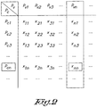
- this target value in this case use is made of a matrix that is stored in the control unit 20, for example.
- FIG. 2 An example of such matrix is shown in figure 2 .
- the matrix gives the combined power that is absorbed by the compressor and the fan as a function of the evaporator pressure p v and the condenser pressure p c .
- the control unit 20 receives the value P vn for the evaporator pressure p v from the means 22. On the basis of this value P vn the control unit 20 determines a target value for the condenser pressure p c at which the joint combined power is a minimum.
- the minimum combined power is equal to x nn and the accompanying target value for the condenser pressure is equal to p cn .
- the control unit 20 will adjust the speed of the fan such that the condenser pressure p c reaches and maintains the determined target value p cn .
- the condenser pressure p c is kept constant and at such a target value that the combined power absorbed by the compressor 5 and the fan 19 is a minimum, which has the advantage that the device 1 will operate under optimum energy-efficient conditions, as the compressor 5 and the fan 19 are the main consumers of energy in the cooling circuit 4.
- control unit 20 is such that the target value of the condenser pressure p c is determined periodically, in other words the control unit 20 periodically determines a target value for the condenser pressure p c from the matrix on the basis of the signal from the means 22.
- the interval with which the target value is determined can be chosen as a function of the variation of the load of the device 1 for example.
- the target value for the condenser pressure p c can also be determined by means of a preprogrammed control algorithm in the control unit 20.
- control unit 20 will determine the power absorbed by the compressor 5 on the basis of the signal from the means 21 and 22, and determine the power absorbed by the fan 19 on the basis of the current speed of the fan 19 so that the combined power can be determined.
- control unit 20 will increase or decrease the speed of the fan 19 by a certain step and again determine the combined power.
- the control unit 20 will determine for what fan 19 speed the combined power was a minimum and will adjust the fan 19 to this speed.
- This control algorithm ensures that the control unit 20 is self-learning as it were and independent of the device 1 and the cooling circuit and consequently can be applied in different devices 1 and cooling circuits 4.
- the fan 19 speed is adjusted to the minimum speed whereby the calculated or set target value for the condenser pressure p c is reached or whereby the condenser pressure p c is as good as equal to the target value.
- This target value may be determined on the basis of the methods described above, or otherwise.
- the calculated or set target value can be determined in many different ways so that the combined power absorbed by the compressor 5 and the fan 19 is a minimum.
- the fan 19 speed can be controlled or adjusted in many different ways by the control unit 20 so that the condenser pressure p c is kept equal to the target value.
- the device 1 is provided with only one heat exchanger 2, it is clear that a number of heat exchangers 2 can also be provided.
Landscapes
- Chemical & Material Sciences (AREA)
- Engineering & Computer Science (AREA)
- Oil, Petroleum & Natural Gas (AREA)
- Thermal Sciences (AREA)
- Analytical Chemistry (AREA)
- General Chemical & Material Sciences (AREA)
- Physics & Mathematics (AREA)
- Chemical Kinetics & Catalysis (AREA)
- Combustion & Propulsion (AREA)
- Mechanical Engineering (AREA)
- General Engineering & Computer Science (AREA)
- Drying Of Solid Materials (AREA)
- Air Conditioning Control Device (AREA)
Priority Applications (1)
| Application Number | Priority Date | Filing Date | Title |
|---|---|---|---|
| PL15736774T PL3140023T3 (pl) | 2014-05-09 | 2015-04-27 | Sposób i urządzenie do osuszania ziębniczego gazu za pomocą wymiennika ciepła z zamkniętym obiegiem chłodzenia |
Applications Claiming Priority (2)
| Application Number | Priority Date | Filing Date | Title |
|---|---|---|---|
| BE2014/0347A BE1021855B1 (nl) | 2014-05-09 | 2014-05-09 | Werkwijze en inrichting voor het koeldrogen van een gas |
| PCT/BE2015/000014 WO2015168753A1 (en) | 2014-05-09 | 2015-04-27 | Method and device for cool-drying a gas using a heat exchanger with closed cooling circuit |
Publications (2)
| Publication Number | Publication Date |
|---|---|
| EP3140023A1 EP3140023A1 (en) | 2017-03-15 |
| EP3140023B1 true EP3140023B1 (en) | 2019-04-17 |
Family
ID=51302570
Family Applications (1)
| Application Number | Title | Priority Date | Filing Date |
|---|---|---|---|
| EP15736774.9A Active EP3140023B1 (en) | 2014-05-09 | 2015-04-27 | Method and device for cool-drying a gas using a heat exchanger with closed cooling circuit |
Country Status (11)
| Country | Link |
|---|---|
| US (1) | US9950294B2 (pl) |
| EP (1) | EP3140023B1 (pl) |
| CN (1) | CN106457130B (pl) |
| BE (1) | BE1021855B1 (pl) |
| DK (1) | DK3140023T3 (pl) |
| ES (1) | ES2736475T3 (pl) |
| HU (1) | HUE045408T2 (pl) |
| PL (1) | PL3140023T3 (pl) |
| PT (1) | PT3140023T (pl) |
| TR (1) | TR201908735T4 (pl) |
| WO (1) | WO2015168753A1 (pl) |
Families Citing this family (5)
| Publication number | Priority date | Publication date | Assignee | Title |
|---|---|---|---|---|
| US11499765B2 (en) * | 2018-08-01 | 2022-11-15 | L'air Liquide, Societe Anonyme Pour L'etude Et L'exploitation Des Procedes Georges Claude | Device and process for refueling containers with pressurized gas |
| EP3714962B1 (de) * | 2019-03-29 | 2021-12-15 | Kaeser Kompressoren SE | Druckluftstation |
| US11369920B2 (en) * | 2019-12-31 | 2022-06-28 | Ingersoll-Rand Industrial U.S., Inc. | Multi-mode air drying system |
| CN113601806A (zh) * | 2021-06-29 | 2021-11-05 | 无锡有孚精工科技有限公司 | 一种模具生产用气液冷却装置、系统及方法 |
| CN116808792B (zh) * | 2023-05-18 | 2026-04-10 | 华能山东发电有限公司烟台发电厂 | 一种双介质压缩空气除水装置 |
Citations (1)
| Publication number | Priority date | Publication date | Assignee | Title |
|---|---|---|---|---|
| WO2006050132A1 (en) * | 2004-10-28 | 2006-05-11 | Emerson Retail Services Inc. | Condenser fan control system |
Family Cites Families (15)
| Publication number | Priority date | Publication date | Assignee | Title |
|---|---|---|---|---|
| NL7607760A (nl) * | 1976-07-14 | 1978-01-17 | Droogtech | Koelinrichting, in het bijzonder voor het drogen van een gas. |
| JPS5640418A (en) * | 1979-09-13 | 1981-04-16 | Toshiba Corp | Dehumidifier |
| GB2183320B (en) * | 1985-11-08 | 1990-07-11 | Ewald Gossler | Method and device for compression of gases |
| JPH11351680A (ja) * | 1998-06-08 | 1999-12-24 | Calsonic Corp | 冷房装置 |
| BE1013150A3 (nl) * | 1999-11-24 | 2001-10-02 | Atlas Copco Airpower Nv | Inrichting en werkwijze voor het koeldrogen. |
| US6516622B1 (en) * | 2000-06-13 | 2003-02-11 | Belair Technologies, Llc | Method and apparatus for variable frequency controlled compressor and fan |
| US6711906B2 (en) * | 2001-04-20 | 2004-03-30 | Hankison International | Variable evaporator control for a gas dryer |
| ITMI20011918A1 (it) * | 2001-09-14 | 2003-03-14 | Domnick Hunter Hiross S P A | Sistema di controllo per essicatori di gas compresso a refrigerazione |
| ATE395566T1 (de) * | 2004-06-10 | 2008-05-15 | Micheletti Impianti S R L | Kälteanlage |
| BE1017362A3 (nl) * | 2006-11-10 | 2008-07-01 | Atlas Copco Airpower Nv | Werkwijze voor het koeldrogen. |
| WO2009091400A1 (en) * | 2008-01-17 | 2009-07-23 | Carrier Corporation | Carbon dioxide refrigerant vapor compression system |
| US20090217679A1 (en) | 2008-02-28 | 2009-09-03 | Optidyn Inc. | Refrigeration cooling system control |
| US20090277197A1 (en) * | 2008-05-01 | 2009-11-12 | Gambiana Dennis S | Evaporator apparatus and method for modulating cooling |
| EP2780649B1 (de) | 2011-11-16 | 2020-09-30 | A-Heat Allied Heat Exchange Technology AG | Verfahren zur minimierung eines energieverbrauchs einer wärmeumwälzmaschine, sowie wärmeumwälzmaschine |
| JP5472391B2 (ja) | 2012-07-31 | 2014-04-16 | ダイキン工業株式会社 | コンテナ用冷凍装置 |
-
2014
- 2014-05-09 BE BE2014/0347A patent/BE1021855B1/nl active
-
2015
- 2015-04-27 TR TR2019/08735T patent/TR201908735T4/tr unknown
- 2015-04-27 CN CN201580024224.9A patent/CN106457130B/zh active Active
- 2015-04-27 US US15/309,619 patent/US9950294B2/en active Active
- 2015-04-27 EP EP15736774.9A patent/EP3140023B1/en active Active
- 2015-04-27 PL PL15736774T patent/PL3140023T3/pl unknown
- 2015-04-27 PT PT15736774T patent/PT3140023T/pt unknown
- 2015-04-27 ES ES15736774T patent/ES2736475T3/es active Active
- 2015-04-27 DK DK15736774.9T patent/DK3140023T3/da active
- 2015-04-27 HU HUE15736774A patent/HUE045408T2/hu unknown
- 2015-04-27 WO PCT/BE2015/000014 patent/WO2015168753A1/en not_active Ceased
Patent Citations (1)
| Publication number | Priority date | Publication date | Assignee | Title |
|---|---|---|---|---|
| WO2006050132A1 (en) * | 2004-10-28 | 2006-05-11 | Emerson Retail Services Inc. | Condenser fan control system |
Also Published As
| Publication number | Publication date |
|---|---|
| PT3140023T (pt) | 2019-06-06 |
| PL3140023T3 (pl) | 2019-08-30 |
| CN106457130A (zh) | 2017-02-22 |
| EP3140023A1 (en) | 2017-03-15 |
| DK3140023T3 (da) | 2019-05-20 |
| US20170128879A1 (en) | 2017-05-11 |
| BE1021855B1 (nl) | 2016-01-22 |
| US9950294B2 (en) | 2018-04-24 |
| WO2015168753A1 (en) | 2015-11-12 |
| ES2736475T3 (es) | 2020-01-02 |
| TR201908735T4 (tr) | 2019-07-22 |
| CN106457130B (zh) | 2020-01-24 |
| HUE045408T2 (hu) | 2019-12-30 |
Similar Documents
| Publication | Publication Date | Title |
|---|---|---|
| US10060663B2 (en) | Cooling circuit, cold drying installation and method for controlling a cooling circuit | |
| EP2232230B1 (en) | Refrigeration system comprising a test chamber with temperature and humidity control | |
| EP3140023B1 (en) | Method and device for cool-drying a gas using a heat exchanger with closed cooling circuit | |
| US11092376B2 (en) | Refrigeration device comprising multiple storage chambers | |
| US10232309B2 (en) | Method and device for cool-drying a gas with circulating cooling liquid with bypass line | |
| JP2005076933A (ja) | 冷凍サイクル装置 | |
| JP6045440B2 (ja) | 空気調和機の制御装置 | |
| US12158282B2 (en) | Variable refrigerant flow system | |
| US9914092B2 (en) | Method and device for cool drying a gas | |
| CN106567237B (zh) | 热泵系统、烘干装置及烘干装置的控制方法 | |
| CN105202656A (zh) | 新风除湿系统和方法 | |
| EP3140026B1 (en) | Method for cool drying a gas | |
| KR101766466B1 (ko) | 무성에 고성능 공기열 히트펌프 시스템 | |
| EP2242966A1 (en) | Method of controlling a heat-rejection heat exchanging side of a refrigerant circuit | |
| WO2015090481A1 (en) | A heat pump system |
Legal Events
| Date | Code | Title | Description |
|---|---|---|---|
| STAA | Information on the status of an ep patent application or granted ep patent |
Free format text: STATUS: THE INTERNATIONAL PUBLICATION HAS BEEN MADE |
|
| PUAI | Public reference made under article 153(3) epc to a published international application that has entered the european phase |
Free format text: ORIGINAL CODE: 0009012 |
|
| STAA | Information on the status of an ep patent application or granted ep patent |
Free format text: STATUS: REQUEST FOR EXAMINATION WAS MADE |
|
| 17P | Request for examination filed |
Effective date: 20161020 |
|
| AK | Designated contracting states |
Kind code of ref document: A1 Designated state(s): AL AT BE BG CH CY CZ DE DK EE ES FI FR GB GR HR HU IE IS IT LI LT LU LV MC MK MT NL NO PL PT RO RS SE SI SK SM TR |
|
| AX | Request for extension of the european patent |
Extension state: BA ME |
|
| DAV | Request for validation of the european patent (deleted) | ||
| DAX | Request for extension of the european patent (deleted) | ||
| TPAC | Observations filed by third parties |
Free format text: ORIGINAL CODE: EPIDOSNTIPA |
|
| STAA | Information on the status of an ep patent application or granted ep patent |
Free format text: STATUS: EXAMINATION IS IN PROGRESS |
|
| 17Q | First examination report despatched |
Effective date: 20171121 |
|
| GRAP | Despatch of communication of intention to grant a patent |
Free format text: ORIGINAL CODE: EPIDOSNIGR1 |
|
| STAA | Information on the status of an ep patent application or granted ep patent |
Free format text: STATUS: GRANT OF PATENT IS INTENDED |
|
| INTG | Intention to grant announced |
Effective date: 20181204 |
|
| GRAS | Grant fee paid |
Free format text: ORIGINAL CODE: EPIDOSNIGR3 |
|
| GRAA | (expected) grant |
Free format text: ORIGINAL CODE: 0009210 |
|
| STAA | Information on the status of an ep patent application or granted ep patent |
Free format text: STATUS: THE PATENT HAS BEEN GRANTED |
|
| AK | Designated contracting states |
Kind code of ref document: B1 Designated state(s): AL AT BE BG CH CY CZ DE DK EE ES FI FR GB GR HR HU IE IS IT LI LT LU LV MC MK MT NL NO PL PT RO RS SE SI SK SM TR |
|
| REG | Reference to a national code |
Ref country code: GB Ref legal event code: FG4D |
|
| REG | Reference to a national code |
Ref country code: CH Ref legal event code: EP |
|
| REG | Reference to a national code |
Ref country code: DE Ref legal event code: R096 Ref document number: 602015028475 Country of ref document: DE |
|
| REG | Reference to a national code |
Ref country code: AT Ref legal event code: REF Ref document number: 1120932 Country of ref document: AT Kind code of ref document: T Effective date: 20190515 Ref country code: IE Ref legal event code: FG4D |
|
| REG | Reference to a national code |
Ref country code: DK Ref legal event code: T3 Effective date: 20190513 |
|
| REG | Reference to a national code |
Ref country code: PT Ref legal event code: SC4A Ref document number: 3140023 Country of ref document: PT Date of ref document: 20190606 Kind code of ref document: T Free format text: AVAILABILITY OF NATIONAL TRANSLATION Effective date: 20190522 |
|
| REG | Reference to a national code |
Ref country code: NL Ref legal event code: FP |
|
| REG | Reference to a national code |
Ref country code: CH Ref legal event code: NV Representative=s name: ORITI PATENTS - FRANCO ORITI, CH |
|
| REG | Reference to a national code |
Ref country code: SE Ref legal event code: TRGR |
|
| REG | Reference to a national code |
Ref country code: LT Ref legal event code: MG4D |
|
| REG | Reference to a national code |
Ref country code: NO Ref legal event code: T2 Effective date: 20190417 |
|
| REG | Reference to a national code |
Ref country code: GR Ref legal event code: EP Ref document number: 20190402123 Country of ref document: GR Effective date: 20191016 |
|
| PG25 | Lapsed in a contracting state [announced via postgrant information from national office to epo] |
Ref country code: AL Free format text: LAPSE BECAUSE OF FAILURE TO SUBMIT A TRANSLATION OF THE DESCRIPTION OR TO PAY THE FEE WITHIN THE PRESCRIBED TIME-LIMIT Effective date: 20190417 Ref country code: HR Free format text: LAPSE BECAUSE OF FAILURE TO SUBMIT A TRANSLATION OF THE DESCRIPTION OR TO PAY THE FEE WITHIN THE PRESCRIBED TIME-LIMIT Effective date: 20190417 Ref country code: LT Free format text: LAPSE BECAUSE OF FAILURE TO SUBMIT A TRANSLATION OF THE DESCRIPTION OR TO PAY THE FEE WITHIN THE PRESCRIBED TIME-LIMIT Effective date: 20190417 |
|
| PG25 | Lapsed in a contracting state [announced via postgrant information from national office to epo] |
Ref country code: BG Free format text: LAPSE BECAUSE OF FAILURE TO SUBMIT A TRANSLATION OF THE DESCRIPTION OR TO PAY THE FEE WITHIN THE PRESCRIBED TIME-LIMIT Effective date: 20190717 Ref country code: RS Free format text: LAPSE BECAUSE OF FAILURE TO SUBMIT A TRANSLATION OF THE DESCRIPTION OR TO PAY THE FEE WITHIN THE PRESCRIBED TIME-LIMIT Effective date: 20190417 Ref country code: LV Free format text: LAPSE BECAUSE OF FAILURE TO SUBMIT A TRANSLATION OF THE DESCRIPTION OR TO PAY THE FEE WITHIN THE PRESCRIBED TIME-LIMIT Effective date: 20190417 |
|
| REG | Reference to a national code |
Ref country code: HU Ref legal event code: AG4A Ref document number: E045408 Country of ref document: HU |
|
| PG25 | Lapsed in a contracting state [announced via postgrant information from national office to epo] |
Ref country code: IS Free format text: LAPSE BECAUSE OF FAILURE TO SUBMIT A TRANSLATION OF THE DESCRIPTION OR TO PAY THE FEE WITHIN THE PRESCRIBED TIME-LIMIT Effective date: 20190817 |
|
| REG | Reference to a national code |
Ref country code: ES Ref legal event code: FG2A Ref document number: 2736475 Country of ref document: ES Kind code of ref document: T3 Effective date: 20200102 |
|
| REG | Reference to a national code |
Ref country code: DE Ref legal event code: R097 Ref document number: 602015028475 Country of ref document: DE |
|
| PG25 | Lapsed in a contracting state [announced via postgrant information from national office to epo] |
Ref country code: RO Free format text: LAPSE BECAUSE OF FAILURE TO SUBMIT A TRANSLATION OF THE DESCRIPTION OR TO PAY THE FEE WITHIN THE PRESCRIBED TIME-LIMIT Effective date: 20190417 Ref country code: SK Free format text: LAPSE BECAUSE OF FAILURE TO SUBMIT A TRANSLATION OF THE DESCRIPTION OR TO PAY THE FEE WITHIN THE PRESCRIBED TIME-LIMIT Effective date: 20190417 Ref country code: EE Free format text: LAPSE BECAUSE OF FAILURE TO SUBMIT A TRANSLATION OF THE DESCRIPTION OR TO PAY THE FEE WITHIN THE PRESCRIBED TIME-LIMIT Effective date: 20190417 Ref country code: MC Free format text: LAPSE BECAUSE OF FAILURE TO SUBMIT A TRANSLATION OF THE DESCRIPTION OR TO PAY THE FEE WITHIN THE PRESCRIBED TIME-LIMIT Effective date: 20190417 |
|
| PLBE | No opposition filed within time limit |
Free format text: ORIGINAL CODE: 0009261 |
|
| STAA | Information on the status of an ep patent application or granted ep patent |
Free format text: STATUS: NO OPPOSITION FILED WITHIN TIME LIMIT |
|
| PG25 | Lapsed in a contracting state [announced via postgrant information from national office to epo] |
Ref country code: SM Free format text: LAPSE BECAUSE OF FAILURE TO SUBMIT A TRANSLATION OF THE DESCRIPTION OR TO PAY THE FEE WITHIN THE PRESCRIBED TIME-LIMIT Effective date: 20190417 |
|
| 26N | No opposition filed |
Effective date: 20200120 |
|
| PG25 | Lapsed in a contracting state [announced via postgrant information from national office to epo] |
Ref country code: SI Free format text: LAPSE BECAUSE OF FAILURE TO SUBMIT A TRANSLATION OF THE DESCRIPTION OR TO PAY THE FEE WITHIN THE PRESCRIBED TIME-LIMIT Effective date: 20190417 |
|
| PG25 | Lapsed in a contracting state [announced via postgrant information from national office to epo] |
Ref country code: CY Free format text: LAPSE BECAUSE OF FAILURE TO SUBMIT A TRANSLATION OF THE DESCRIPTION OR TO PAY THE FEE WITHIN THE PRESCRIBED TIME-LIMIT Effective date: 20190417 |
|
| PG25 | Lapsed in a contracting state [announced via postgrant information from national office to epo] |
Ref country code: MT Free format text: LAPSE BECAUSE OF FAILURE TO SUBMIT A TRANSLATION OF THE DESCRIPTION OR TO PAY THE FEE WITHIN THE PRESCRIBED TIME-LIMIT Effective date: 20190417 |
|
| REG | Reference to a national code |
Ref country code: AT Ref legal event code: UEP Ref document number: 1120932 Country of ref document: AT Kind code of ref document: T Effective date: 20190417 |
|
| PG25 | Lapsed in a contracting state [announced via postgrant information from national office to epo] |
Ref country code: MK Free format text: LAPSE BECAUSE OF FAILURE TO SUBMIT A TRANSLATION OF THE DESCRIPTION OR TO PAY THE FEE WITHIN THE PRESCRIBED TIME-LIMIT Effective date: 20190417 |
|
| P01 | Opt-out of the competence of the unified patent court (upc) registered |
Effective date: 20230602 |
|
| PGFP | Annual fee paid to national office [announced via postgrant information from national office to epo] |
Ref country code: NL Payment date: 20250427 Year of fee payment: 11 |
|
| PGFP | Annual fee paid to national office [announced via postgrant information from national office to epo] |
Ref country code: LU Payment date: 20250428 Year of fee payment: 11 |
|
| PGFP | Annual fee paid to national office [announced via postgrant information from national office to epo] |
Ref country code: FI Payment date: 20250425 Year of fee payment: 11 |
|
| PGFP | Annual fee paid to national office [announced via postgrant information from national office to epo] |
Ref country code: PL Payment date: 20250331 Year of fee payment: 11 Ref country code: DE Payment date: 20250429 Year of fee payment: 11 |
|
| PGFP | Annual fee paid to national office [announced via postgrant information from national office to epo] |
Ref country code: GB Payment date: 20250428 Year of fee payment: 11 Ref country code: ES Payment date: 20250505 Year of fee payment: 11 Ref country code: DK Payment date: 20250425 Year of fee payment: 11 |
|
| PGFP | Annual fee paid to national office [announced via postgrant information from national office to epo] |
Ref country code: HU Payment date: 20250422 Year of fee payment: 11 Ref country code: NO Payment date: 20250429 Year of fee payment: 11 |
|
| PGFP | Annual fee paid to national office [announced via postgrant information from national office to epo] |
Ref country code: IT Payment date: 20250422 Year of fee payment: 11 Ref country code: BE Payment date: 20250428 Year of fee payment: 11 |
|
| PGFP | Annual fee paid to national office [announced via postgrant information from national office to epo] |
Ref country code: PT Payment date: 20250407 Year of fee payment: 11 |
|
| PGFP | Annual fee paid to national office [announced via postgrant information from national office to epo] |
Ref country code: FR Payment date: 20250425 Year of fee payment: 11 |
|
| PGFP | Annual fee paid to national office [announced via postgrant information from national office to epo] |
Ref country code: GR Payment date: 20250430 Year of fee payment: 11 |
|
| PGFP | Annual fee paid to national office [announced via postgrant information from national office to epo] |
Ref country code: CH Payment date: 20250501 Year of fee payment: 11 |
|
| PGFP | Annual fee paid to national office [announced via postgrant information from national office to epo] |
Ref country code: AT Payment date: 20250402 Year of fee payment: 11 |
|
| PGFP | Annual fee paid to national office [announced via postgrant information from national office to epo] |
Ref country code: TR Payment date: 20250418 Year of fee payment: 11 |
|
| PGFP | Annual fee paid to national office [announced via postgrant information from national office to epo] |
Ref country code: CZ Payment date: 20250408 Year of fee payment: 11 |
|
| PGFP | Annual fee paid to national office [announced via postgrant information from national office to epo] |
Ref country code: IE Payment date: 20250428 Year of fee payment: 11 |
|
| PGFP | Annual fee paid to national office [announced via postgrant information from national office to epo] |
Ref country code: SE Payment date: 20250430 Year of fee payment: 11 |