EP3140071B1 - Vorrichtung zur kühlmittelversorgung, steuerung für eine solche vorrichtung und verfahren zum betrieb einer solchen kühlmittelversorgung - Google Patents
Vorrichtung zur kühlmittelversorgung, steuerung für eine solche vorrichtung und verfahren zum betrieb einer solchen kühlmittelversorgung Download PDFInfo
- Publication number
- EP3140071B1 EP3140071B1 EP16710912.3A EP16710912A EP3140071B1 EP 3140071 B1 EP3140071 B1 EP 3140071B1 EP 16710912 A EP16710912 A EP 16710912A EP 3140071 B1 EP3140071 B1 EP 3140071B1
- Authority
- EP
- European Patent Office
- Prior art keywords
- valve
- coolant
- return
- return line
- pressure
- Prior art date
- Legal status (The legal status is an assumption and is not a legal conclusion. Google has not performed a legal analysis and makes no representation as to the accuracy of the status listed.)
- Active
Links
Images


Classifications
-
- B—PERFORMING OPERATIONS; TRANSPORTING
- B23—MACHINE TOOLS; METAL-WORKING NOT OTHERWISE PROVIDED FOR
- B23K—SOLDERING OR UNSOLDERING; WELDING; CLADDING OR PLATING BY SOLDERING OR WELDING; CUTTING BY APPLYING HEAT LOCALLY, e.g. FLAME CUTTING; WORKING BY LASER BEAM
- B23K11/00—Resistance welding; Severing by resistance heating
- B23K11/30—Features relating to electrodes
- B23K11/3009—Pressure electrodes
- B23K11/3018—Cooled pressure electrodes
-
- B—PERFORMING OPERATIONS; TRANSPORTING
- B23—MACHINE TOOLS; METAL-WORKING NOT OTHERWISE PROVIDED FOR
- B23K—SOLDERING OR UNSOLDERING; WELDING; CLADDING OR PLATING BY SOLDERING OR WELDING; CUTTING BY APPLYING HEAT LOCALLY, e.g. FLAME CUTTING; WORKING BY LASER BEAM
- B23K26/00—Working by laser beam, e.g. welding, cutting or boring
- B23K26/70—Auxiliary operations or equipment
- B23K26/702—Auxiliary equipment
- B23K26/703—Cooling arrangements
-
- B—PERFORMING OPERATIONS; TRANSPORTING
- B23—MACHINE TOOLS; METAL-WORKING NOT OTHERWISE PROVIDED FOR
- B23K—SOLDERING OR UNSOLDERING; WELDING; CLADDING OR PLATING BY SOLDERING OR WELDING; CUTTING BY APPLYING HEAT LOCALLY, e.g. FLAME CUTTING; WORKING BY LASER BEAM
- B23K37/00—Auxiliary devices or processes, not specially adapted for a procedure covered by only one of the other main groups of this subclass
- B23K37/003—Cooling means for welding or cutting
-
- B—PERFORMING OPERATIONS; TRANSPORTING
- B23—MACHINE TOOLS; METAL-WORKING NOT OTHERWISE PROVIDED FOR
- B23K—SOLDERING OR UNSOLDERING; WELDING; CLADDING OR PLATING BY SOLDERING OR WELDING; CUTTING BY APPLYING HEAT LOCALLY, e.g. FLAME CUTTING; WORKING BY LASER BEAM
- B23K9/00—Arc welding or cutting
- B23K9/24—Features related to electrodes
- B23K9/28—Supporting devices for electrodes
- B23K9/285—Cooled electrode holders
Definitions
- the invention relates to a device for supplying coolant to a processing device to be supplied with fluid coolant.
- the coolant is usually water.
- the processing device may be an induction device with a cooled induction coil. It is essential that an area of the processing device, in particular a tool, is integrated in an open or closed coolant circuit.
- the coolant circuit includes a flow and a return, regularly defined by appropriate coolant lines.
- the present invention is therefore based on the object to eliminate the aforementioned problems at least as far as possible. It should be effectively prevented by simple means that coolant enters the outside. It should not depend on the skill of the operator, but it should be ensured that regardless of the respective handling of the escape of coolant from the coolant circuit is effectively avoided.
- the coolant circuit comprises a conveyor for conveying the coolant. If this conveyor, regularly a pump, a cylinder-piston arrangement, etc., deactivated, no further coolant is nachgediant from the coolant source. However, the pressure prevailing in the coolant line internal pressure would be sufficient to cause contamination of the environment with coolant when opening the coolant circuit. Consequently, disabling the conveyor or closing the lines is not sufficient.
- a special control device is provided, namely, on the one hand serves to deactivate the conveyor and on the other hand causes a certain empty suction of flow and / or return of the coolant circuit. This is done in such a way that in the coolant circuit, in particular in the region of the tool to be cooled, an at least slight negative pressure prevails, namely in the flow line and / or in the return line. This negative pressure causes when opening the coolant circuit no coolant or at most least amounts of coolant get outside the coolant circuit.
- control device two different measures are taken by the control device, namely on the one hand deactivating the conveyor and on the other hand generating a negative pressure in the flow line and / or in the return line.
- the term "conveyor” is to be understood in the broadest sense. It is also conceivable that the coolant circuit is connected to a domestic water network, so that a special conveyor is not required. As a further source of coolant is a stationary or mobile cooling water supply with tank, pump and recooler in question, namely for individual supply. Instead of switching off a conveyor shut-off valves can be closed in the flow and / or in the return, so that no further pressure can be built from the source of the coolant. The negative pressure created in the refrigerant circuit effectively prevents coolant from leaking outside as the tool is removed and the tool is removed.
- the locking device can be activated manually or mechanically, electrically or pneumatically, as needed. This means that during maintenance, malfunction, in particular in the case of a defect in the tool, for example on the cap of a robot welding device (cap break-off) or in the case of a defective hose (tube burst), the operator activates the control device.
- the defect could be detected automatically on the tool and the activation of the control device could also be carried out automatically, it being further advantageous to output a signal in parallel - optically and / or acoustically and / or electrically / electronically ,
- the control device comprises means or mechanisms which act directly or indirectly on the coolant flow and the coolant return.
- the locking device comprises a main valve supplied with compressed air, which may be, for example, a 3/2-way valve or a 4/2-way valve or a 5/2-way valve. In concrete terms, this can be a single valve or the combination of valves in the sense of a valve terminal.
- the main valve is supplied with compressed air, wherein the main valve to an operation, preferably by compressed air (also mechanically by hand or electrically) closes the flow and / or the return respectively via a shut-off valve.
- shut-off valves in the flow and / or return are closed, that is, when a coolant circulation is prevented in the coolant circuit, a further valve or preferably formed in the return bypass is opened via a signal of the main valve, via which the return line and possibly the flow line emptied into the return to the sink.
- a pump provided there may be flowed through. In the context of such an embodiment, no bypass is required, but only a valve which prevents the backflow of the cooling medium in the return.
- the valve may be a check valve.
- a pump Via the signal of the main valve, a pump is activated, which pumps off the return line and possibly the flow line, such that in the coolant circuit, that is in the flow line and in the return line, at least a slight negative pressure.
- This negative pressure can be detected or checked and possibly displayed in analog or digital, so that the operator has a visual control.
- the opening and closing of the bypass and the activation / deactivation of the pump can be delayed, preferably via a fixed or adjustable delay valve or a corresponding valve device, wherein a corresponding delay unit, a throttle device, a check valve, a storage mechanism and an example pressure / may include spring loaded multiway valve.
- the previously discussed main valve or another valve preferably controls pneumatically a signal valve device, wherein the signal valve device compares the pressures of two or more fluids, wherein one of the fluids is the coolant and the pressure to be detected according to the coolant pressure in the flow and / or in the return ,
- the signal valve device compares the pressures of two or more fluids, wherein one of the fluids is the coolant and the pressure to be detected according to the coolant pressure in the flow and / or in the return ,
- the water pressure in the flow is compared with the air pressure coming from the main valve by the signal valve device.
- the pump for generating an at least slight negative pressure in the coolant circuit and the bypass valve so that prior to removal of the tool required to avoid leakage of coolant vacuum is set.
- the signal valve device may also compare the fluid pressure in the lines through a measuring cell and advance an electrical / pneumatic signal.
- the usual operating state is adjustable by reset, namely manually or mechanically, electrically or hydraulically.
- the entire device together with the connections, compressed air and possibly electricity, can be accommodated in a mounting frame in the smallest space and handle accordingly. This is another advantage.
- control comprises the current-specific features of the previously discussed device. It is primarily about the control device for deactivating the delivery device and for empty suction of flow and / or return, so that in the region of the tool to be cooled at least a slight negative pressure prevails in the flow line and / or in the return line, so that when loosening the tool accidental leakage of the coolant is avoided.
- the control according to the invention comprises the previously discussed main valve, the signal valve and the delay valve, there are hydraulic and pneumatic components are included to meet the claimed requirements.
- the inventive method solves the underlying problem by the further independent claim 11, wherein the method of use the device according to the invention for coolant supply is used.
- the method steps can be realized with a very special control device comprising the main valve, the signal valve and the delay valve.
- the control acts between the supply of coolant and compressed air, the tool and the discharge / Auslas furnishen end of the return line, to the effect that the supply of coolant can be blocked and the coolant circuit can be brought to at least low negative pressure.
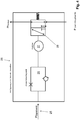
- Fig. 1 shows in a schematic diagram, greatly simplified, the basic function of an embodiment of an inventive Device which serves to supply coolant to the merely indicated cap as a tool 1 of a welding device 2.
- the tool 1 is flowed through by coolant or water and thus forms part of the coolant circuit 3.
- the coolant circuit 3 comprises a flow 4 and a return 5.
- the tool may also have a plurality of cooling circuits, which are divided by the suction device, for. B. the supply for a transformer.
- various circuit arms may be provided as separate supply and return lines, which reconnect after the tool.
- the coolant comes from a coolant source 6, flows through the feed 4 through the tool 1 and via the return line 5 into a coolant sink 7.
- the coolant source 6 and the coolant sink 7 can be united with the interposition of a filter device. It is also conceivable that the coolant is removed as water from a river and returned there again. Likewise, it is conceivable to use a water connection or a water supply line as the coolant source and as sink the sewage network.
- a stationary or mobile cooling water supply with pump, tank and recooler can be provided, which can be used as a single supply.
- a control device 8 is provided, which is for deactivating the in Fig. 1 not shown conveyor or to block flow 4 and return 5 is used.
- the control device 8 further serves for empty suction of supply 4 and / or return, such that in the region of the tool 1 to be cooled at least a slight negative pressure in the flow line 9 and / or in the return line 12 prevails. This negative pressure ensures that when removing the tool 1, the coolant remains in the coolant circuit 3, in any case does not get outside of the coolant circuit 3. Contamination of the environment and the operator is effectively avoided.
- Fig. 1 is further indicated that the control device 8 is activated via a signal, namely, when the change of the tool 1 is pending or should be completed, namely due to a defect, a malfunction, a maintenance, etc ..
- This signal can manually or be triggered mechanically, electrically or pneumatically.
- Fig. 2 shows in a schematic diagram, the control device 8, which corresponds to the above statements Fig. 1 on the flow 4, the return 5 and a suction of the coolant circuit 3 acts.
- Fig. 2 shows that in the flow 4 and in the flow line 9, a shut-off valve 10 is provided which can be activated via a main valve 11 and a main valve device. Furthermore, a shut-off valve 13 is also provided in the return 5 or in the return line 12, likewise activatable via the main valve 11.
- the main valve 11 is supplied from outside the control device 8 with compressed air, namely from a compressed air source 14th
- the main valve 11 is switched via a signal 15, whereby the water supply via the shut-off valves 10, 13 is closed.
- a signal 15 for this example, 2- or 3-way ball valves can be provided.
- a bypass 16 is opened and a pump 17 is activated, wherein the signal is generated via the main valve 11.
- the compressed air signal (supply) is conveyed from the main valve via the delay valve or directional control valve to the pump 17. It should be noted that the signal does not necessarily have to come from the main valve. Rather, a further valve may be provided, for. B. using a valve terminal.
- the pressure or pressure drop is preferably measured in the supply line 4.
- a pressure comparison takes place in a signal valve arrangement 18, here a pressure comparison between the pressure in the flow 4 and an air pressure.
- the signal valve arrangement 18 includes as an integral part of a kind of pressure balance, which can compare pressures of different or even the same flow media.
- the falling water pressure in the supply 4 is compared with a constant air pressure.
- the signal valve arrangement 18 transmits, as a signal or manipulated variable, an air pressure 19 as soon as the detected water pressure falls below a predefinable limit value.
- the limit can be defined for both negative and positive pressure in the cooling water pipe.
- the switching signal at a negative pressure has the advantage that the time delay valve can be designed as a normal directional control valve.
- the air pressure 19 or the corresponding signal is forwarded as a constant air signal and to a delay valve 20.
- This delay valve 20 may be equipped with a time constant serving for delay. It is also conceivable to set the delay variable. Instead of the delay valve and a directional control valve may be provided.
- the previously mentioned bypass 16 includes a bypass line 21 and a check valve 22.
- the check valve 22 When the check valve 22 is open, can be on the Pump 17 refrigerant from the return line 5 and thus also indirectly, suck from the flow 4, namely in the coolant sink 7.
- the check valve 13 in the return is closed.
- the pump can also be flowed through. In this case, no bypass is required, but only a valve that prevents the return of the cooling medium in the return.
- the control device 8 can be reset, so that the machining operation can start again.
- the reset can be done manually, electrically or pneumatically.
- Fig. 3 shows in a schematic diagram, in detail, an embodiment of a signal valve 18, which serves to compare the signals of different media in terms of a water / pressure balance.
- a corresponding arrangement 23 is provided. To avoid repetition, refer to the general description and description of Fig. 2 directed.
- a pressure regulator 24 is provided, which is fixed. It is also conceivable to provide a free adjustability of the pressure regulator 24.
- Fig. 3 further shows a 3/2-way valve 29 for venting. From there, the signal is sent to the actual delay valve 20.
- Fig. 4 shows a schematic view of the delay valve 20, as part of the control device 8.
- the delay valve 20 is acted upon by the signal valve assembly 18 forth with a signal valve pressure 25. It may include pneumatic components to provide the desired deceleration, such as a throttle with check valve 26, a reservoir, a time-delayed directional control valve 28, etc. It is essential to the delay valve 20 that a predetermined delay be implemented there. Alternatively, the delay with respect to the output signal, that is, the signal leading to the pump 17, could be changeable or adjustable. A limit can be at Negative pressure in the cooling water line switch. The switching signal at negative pressure has the advantage that the time delay valve can be designed as a normal directional control valve.
- controller can also be constructed in other ways.
- a signal valve and a simplified pump in the form of a suction cylinder in the return may be required.
- a bypass is not required in the context of such an embodiment.
- the cooling water supply is closed by a shut-off valve, whereby the signal valve compares the supply and return pressure.
- a pneumatic signal is sent to the suction cylinder and to the shut-off valve in the cooling water return when the return pressure and flow pressure are equalized. It is only necessary that the two pressures approach each other and are not identical.
Landscapes
- Engineering & Computer Science (AREA)
- Mechanical Engineering (AREA)
- Physics & Mathematics (AREA)
- Optics & Photonics (AREA)
- Plasma & Fusion (AREA)
- Auxiliary Devices For Machine Tools (AREA)
Description
- Die Erfindung betrifft eine Vorrichtung zur Kühlmittelversorgung einer mit fluidem Kühlmittel zu versorgenden Bearbeitungseinrichtung. Bei dem Kühlmittel handelt es sich regelmäßig um Wasser. Lediglich beispielhaft sei auf eine Schweißeinrichtung oder einen Schweißroboter verwiesen, bei der bzw. bei dem die Schweißkappe zu kühlen ist. Ebenso kann es sich bei der Bearbeitungseinrichtung um eine Induktionseinrichtung mit gekühlter Induktionsspule handeln. Wesentlich ist, dass ein Bereich der Bearbeitungseinrichtung, insbesondere ein Werkzeug, in einen offenen oder geschlossenen Kühlmittelkreislauf eingebunden ist. Der Kühlmittelkreislauf umfasst einen Vorlauf und eine Rücklauf, regelmäßig definiert durch entsprechende Kühlmittelleitungen.
- Aus der Praxis sind solche Vorrichtungen hinlänglich bekannt. Diese Vorrichtungen sind insbesondere dann in Bezug auf die Handhabung des Kühlmittels problematisch, wenn es darum geht, das im Kühlmittelkreislauf befindliche Werkzeug (es bildet einen Teil des Kühlmittelkreislaufs) zu Wartungs- oder Reparaturzwecken auszutauschen. Gleiches gilt bei Störungen oder bei Werkzeugverlust, beispielsweise hervorgerufen durch Kappenabriss oder durch einen geplatzten Schlauch. Der Kühlmittelkreislauf steht unter zumindest geringem Druck, so dass beim Entfernen des Werkzeugs Kühlmittel in die Umgebung tritt. Bei belastetem Kühlmittel besteht die Gefahr der Kontamination der Umgebung. Bedienpersonen sind regelmäßig den Belastungen durch das Kühlmittel ausgesetzt, beispielsweise bei Keimbelastung des Kühlmittels.
- Aus der Praxis ist es bereits bekannt, vor dem Werkzeugwechsel die die Zirkulation des Kühlmittels bedingende Pumpe auszuschalten. Dies reicht jedoch nicht aus, um den Austritt von Kühlmittel an den Verbindungsstellen zu unterbinden. Hinzu kommt die Problematik langer bzw. sehr langer elastischer Kühlmittelleitungen, die aufgrund des Kühlmitteldrucks zumindest geringfügig ausgedehnt sind. Beim Öffnen der Verbindungsstellen zum Werkzeug hin schrumpft die Leistung und es gelangt unwillkürlich Kühlmittel in die Umgebung. Eine Vorrichtung mit den Merkmalen des Anspruchs 1 ist aus der
WO-A-2010 05368 - Der vorliegenden Erfindung liegt daher die Aufgabe zugrunde, die zuvor genannten Probleme zumindest weitestgehend zu eliminieren. Es soll mit einfachen Mitteln wirksam verhindert werden, dass Kühlmittel nach außen tritt. Dabei soll es nicht auf das Geschickt der Bedienperson ankommen, vielmehr soll sichergestellt sein, dass ungeachtet der jeweiligen Handhabung der Austritt von Kühlmittel aus dem Kühlmittelkreislauf wirksam vermieden ist.
- Voranstehende Aufgabe ist in Bezug auf die Vorrichtung durch die Merkmale des Anspruchs 1 gelöst. Danach ist zunächst wesentlich, dass der Kühlmittelkreislauf eine Fördereinrichtung zum Fördern des Kühlmittels umfasst. Wird diese Fördereinrichtung, regelmäßig eine Pumpe, eine Zylinder-Kolben-Anordnung, etc., deaktiviert, wird aus der Kühlmittelquelle kein weiteres Kühlmittel nachgefördert. Der in der Kühlmittelleitung herrschende Innendruck wäre jedoch ausreichend, beim Öffnen des Kühlmittelkreislaufs eine Kontamination der Umgebung mit Kühlmittel zu verursachen. Folglich reicht das Deaktivieren der Fördereinrichtung oder das Schließen der Leitungen nicht aus.
- In weiter erfindungsgemäßer Weise ist eine besondere Steuereinrichtung vorgesehen, die nämlich einerseits zum Deaktivieren der Fördereinrichtung dient und andererseits ein gewisses Leersaugen von Vorlauf- und/oder Rücklauf des Kühlmittelkreislaufs verursacht. Dies erfolgt derart, dass im Kühlmittelkreislauf, insbesondere im Bereich des zu kühlenden Werkzeugs, ein zumindest geringfügiger Unterdruck herrscht, nämlich in der Vorlaufleitung und/oder in der Rücklaufleitung. Dieser Unterdruck bewirkt, dass beim Öffnen des Kühlmittelkreislaufs kein Kühlmittel oder allenfalls geringste Mengen an Kühlmittel nach außerhalb des Kühlmittelkreislaufs gelangen.
- In erfindungsgemäßer Weise werden durch die Steuereinrichtung zwei unterschiedliche Maßnahmen vorgenommen, nämlich zum Einen ein Deaktivieren der Fördereinrichtung und zum Anderen ein Erzeugen von Unterdruck in der Vorlaufleitung und/oder in der Rücklaufleitung.
- An dieser Stelle sei angemerkt, dass der Begriff "Fördereinrichtung" im weitesten Sinne zu verstehen ist. Ebenso ist es denkbar, dass der Kühlmittelkreislauf an ein häusliches Wassernetz angeschlossen wird, so dass eine besondere Fördereinrichtung nicht erforderlich ist. Als weitere Kühlmittelquelle kommt eine stationäre oder mobile Kühlwasserversorgung mit Tank, Pumpe und Rückkühler in Frage, nämlich zur Einzelversorgung. Anstelle des Abschaltens einer Fördereinrichtung lassen sich im Vorlauf und/oder im Rücklauf Absperrventile schließen, so dass aus der Quelle des Kühlmittels kein weiterer Druck mehr aufgebaut werden kann. Der im Kühlmittelkreislauf erzeugte Unterdruck vermeidet wirksam, dass Kühlmittel beim Entfernen des Werkzeugs und bei entferntem Werkzeug nach außen dringt.
- Die Sperreinrichtung kann manuell bzw. mechanisch, elektrisch oder pneumatisch aktiviert werden, je nach Bedarf. Dies bedeutet, dass bei Wartung, Störung, insbesondere bei einem Defekt am Werkzeug, beispielsweise an der Kappe eines Roboter-Schweißgeräts (Kappenabriss) oder bei defektem Schlauch (Schlauchplatzer), die Bedienperson eine Aktivierung der Steuereinrichtung vornimmt. Im Rahmen einer ganz besonders vorteilhaften Ausgestaltung könnte der Defekt am Werkzeug automatisch erkannt werden und könnte die Aktivierung der Steuereinrichtung entsprechend ebenfalls automatisch erfolgen, wobei es von weiterem Vorteil ist, parallel ein Signal - optisch und/oder akustisch und/oder elektrisch/elektronisch - auszugeben.
- Entsprechend den voranstehenden Ausführungen umfasst die Steuereinrichtung Mittel bzw. Mechanismen, die auf den Kühlmittelvorlauf und den Kühlmittelrücklauf unmittelbar oder mittelbar wirken. Im Konkreten umfasst die Sperreinrichtung ein mit Druckluft versorgtes Hauptventil, wobei es sich dabei beispielsweise um ein 3/2-Wegeventil oder ein 4/2-Wegeventil oder ein 5/2-Wegeventil handeln kann. Es kann sich dabei im Konkreten um ein Einzelventil oder um die Kombination von Ventilen im Sinne einer Ventilinsel handeln.
- Jedenfalls ist das Hauptventil mit Druckluft versorgt, wobei das Hauptventil auf eine Betätigung hin, vorzugsweise per Druckluft (auch mechanisch per Hand oder elektrisch) den Vorlauf und/oder den Rücklauf jeweils über ein Absperrventil schließt.
- Wenn die Absperrventile im Vorlauf und/oder Rücklauf geschlossen sind, das heißt wenn eine Kühlmittelzirkulation im Kühlmittelkreislauf unterbunden ist, wird über eine Signal des Hauptventils ein weiteres Ventil oder ein vorzugsweise im Rücklauf ausgebildeter Bypass geöffnet, über den sich die Rücklaufleitung und ggf. die Vorlaufleitung in den Rücklauf hin zur Senke entleert. Es sei angemerkt, dass eine dort vorgesehene Pumpe durchströmt sein kann. Im Rahmen einer solchen Ausgestaltung ist kein Bypass erforderlich, vielmehr lediglich ein Ventil, welches das Rückfließen des Kühlmediums im Rücklauf verhindert. Bei dem Ventil kann es sich um ein Rückschlagventil handeln.
- Über das Signal des Hauptventils wird eine Pumpe aktiviert, die die Rücklaufleitung und ggf. die Vorlaufleitung abpumpt, dergestalt, dass im Kühlmittelkreislauf, das heißt in der Vorlaufleitung und in der Rücklaufleitung, ein zumindest geringer Unterdruck entsteht. Dieser Unterdruck kann detektiert bzw. überprüft und ggf. analog oder digital angezeigt werden, damit die Bedienperson eine visuelle Kontrolle hat.
- Das Öffnen und das Schließen des Bypass und die Aktivierung/Deaktivierung der Pumpe kann zeitverzögert erfolgen, vorzugsweise über ein fest eingestelltes oder einstellbares Verzögerungsventil bzw. eine entsprechende Ventileinrichtung, wobei eine entsprechende Verzögerungseinheit eine Drosseleinrichtung, ein Rückschlagventil, einen Speichermechanismus und ein beispielsweise druck-/federbelastetes Mehrwegeventil umfassen kann.
- Das zuvor bereits erörterte Hauptventil oder ein weiteres Ventil steuert vorzugsweise pneumatisch eine Signalventileinrichtung an, wobei die Signalventileinrichtung die Drücke zweier oder mehrerer Fluide miteinander vergleicht, wobei eines der Fluide das Kühlmittel und der zu delektierende Druck entsprechend der Kühlmitteldruck im Vorlauf und/oder im Rücklauf ist. So wird durch die Signalventileinrichtung insbesondere der Wasserdruck im Vorlauf mit dem vom Hauptventil kommenden Luftdruck verglichen. Bei Unterschreiten/Überschreiten eines Grenzwerts wird per konstantem Fluiddruck, insbesondere per konstantem Luftdruck, die Pumpe zum Erzeugen eines zumindest geringfügigen Unterdrucks im Kühlmittelkreislauf und das Bypassventil angesteuert, so dass vor dem Entfernen des Werkzeugs der zur Vermeidung eines Austretens von Kühlmittel erforderliche Unterdruck eingestellt wird.
- Die Signalventileinrichtung kann auch den Fluiddruck in den Leitungen durch eine Messzelle vergleichen und ein elektrisches/pneumatisches Signal weiterschalten.
- Nach dem Werkzeugwechsel, das heißt nach dem Schließen des Kühlmittelkreislaufs, ist der übliche Betriebszustand per Reset einstellbar, nämlich manuell bzw. mechanisch, elektrisch oder hydraulisch.
- Die gesamte Vorrichtung nebst den Anschlüssen, Druckluft und ggf. Strom, lässt sich in einem Montagerahmen auf kleinstem Raum unterbringen und entsprechend handhaben. Dies ist von weiterem Vorteil.
- In Bezug auf die erfindungsgemäße Steuerung ist die zugrundeliegende Aufgabe durch die Merkmale des nebengeordneten Anspruchs 10 gelöst. Dabei ist wesentlich, dass die Steuerung die stromspezifischen Merkmalen der zuvor erörterten Vorrichtung umfasst. Dabei geht es in erster Linie um die Steuerungseinrichtung zum Deaktivieren der Förderungseinrichtung und zum Leersaugen von Vorlauf und/oder Rücklauf, so dass im Bereich des zu kühlenden Werkzeugs ein zumindest geringfügiger Unterdruck in der Vorlaufleitung und/oder in der Rücklaufleitung herrscht, so dass beim Lösen des Werkzeugs ein unbeabsichtigtes Austreten des Kühlmittels vermieden ist.
- Die erfindungsgemäße Steuerung umfasst das zuvor erörterte Hauptventil, das Signalventil und das Verzögerungsventil, wobei dort hydraulische und pneumatische Bauteile enthalten sind, um den beanspruchten Anforderungen gerecht zu werden.
- Das erfindungsgemäße Verfahren löst die zugrundeliegende Aufgabe durch den weiter nebengeordneten Anspruch 11, wobei das Verfahren zur Anwendung bei der erfindungsgemäßen Vorrichtung zur Kühlmittelversorgung dient. Die Verfahrensschritte lassen sich mit einer ganz besonderen Steuerungseinrichtung realisieren, die das Hauptventil, das Signalventil und das Verzögerungsventil umfasst. Die Steuerung wirkt zwischen der Versorgung mit Kühlmittel und Druckluft, dem Werkzeug und dem ablass-/auslasseitigen Ende der Rücklaufleitung, dahingehend, dass die Versorgung mit Kühlmittel sperrbar und der Kühlmittelkreislauf auf zumindest geringen Unterdruck verbringbar ist.
- Es gibt nun verschiedene Möglichkeiten, die Lehre der vorliegenden Erfindung in vorteilhafter Weise auszugestalten und weiterzubilden. Dazu ist einerseits auf die dem Anspruch 1 nachgeordneten Ansprüche und andererseits auf die nachfolgende Erläuterung eines bevorzugten Ausführungsbeispiels der Erfindung anhand der Zeichnung zu verweisen. In Verbindung mit der Erläuterung des bevorzugten Ausführungsbeispiels der Erfindung anhand der Zeichnung werden auch im Allgemeinen bevorzugte Ausgestaltungen und Weiterbildungen der Lehre erläutert. In der Zeichnung zeigen
- Fig. 1
- in einem schematischen Diagramm/Schaltbild die grundsätzliche Anordnung einer erfindungsgemäßen Vorrichtung mit entsprechender Steuerrung,
- Fig. 2
- in einem schematischen Diagramm/Schaltbild, im Detail, die Steuereinrichtung der erfindungsgemäßen Vorrichtung,
- Fig. 3
- in einer schematischen Detailansicht den Aufbau eines erfindungsgemäßen Signalventils, zum Vergleichen unterschiedlicher Drucksignale und
- Fig. 4
- in einer schematischen Detailansicht den Aufbau eines Verzögerungsventils, welches fest oder einstellbar ausgeführt sein kann.
-
Fig. 1 zeigt in einem schematischen Diagramm, stark vereinfacht die grundsätzliche Funktion eines Ausführungsbeispiels einer erfindungsgemäßen Vorrichtung, die zur Kühlmittelversorgung der lediglich angedeuteten Kappe als Werkzeug 1 einer Schweißeinrichtung 2 dient. Das Werkzeug 1 ist von Kühlmittel bzw. Wasser durchströmt und bildet somit einen Teil des Kühlmittelkreislaufs 3. Der Kühlmittelkreislauf 3 umfasst einen Vorlauf 4 und einen Rücklauf 5. Das Werkzeug kann auch mehrere Kühlkreisläufe haben, die sich nach der Absaugvorrichtung aufteilen, z. B. die Versorgung für einen Trafo. So können verschiedene Kreislaufarme als separate Vor- und Rücklaufleitungen vorgesehen sein, die sich nach dem Werkzeug wieder verbinden. - Das Kühlmittel stammt aus einer Kühlmittelquelle 6, strömt über den Vorlauf 4 durch das Werkzeug 1 und über den Rücklauf 5 in eine Kühlmittelsenke 7. Die Kühlmittelquelle 6 und die Kühlmittelsenke 7 können unter Zwischenschaltung einer Filtereinrichtung vereint sein. Ebenso ist es denkbar, dass das Kühlmittel als Wasser aus einem Fluss entnommen und dorthin wieder zurückgeführt wird. Ebenso ist es denkbar, als Kühlmittelquelle einen Wasseranschluss bzw. eine Wasserversorgungsleitung zu nutzen und als Senke das Abwassernetz. Wie bereits im allgemeinen Teil der Beschreibung angemerkt, kann als weitere Kühlmittelquelle eine stationäre bzw. mobile Kühlwasserversorgung mit Pumpe, Tank und Rückkühler vorgesehen sein, die als Einzelversorgung nutzbar ist.
- In
Fig. 1 ist des Weiteren angedeutet, dass in erfindungsgemäßer Weise eine Steuereinrichtung 8 vorgesehen ist, die zum Deaktivieren der inFig. 1 nicht gezeigten Fördereinrichtung bzw. zum Sperren von Vorlauf 4 und Rücklauf 5 dient. - Die Steuereinrichtung 8 dient des Weiteren zum Leersaugen von Vorlauf 4 und/oder Rücklaufs, derart, dass im Bereich des zu kühlenden Werkzeugs 1 ein zumindest geringfügiger Unterdruck in der Vorlaufleitung 9 und/oder in der Rücklaufleitung 12 herrscht. Dieser Unterdruck sorgt dafür, dass beim Entfernen des Werkzeugs 1 das Kühlmittel im Kühlmittelkreislauf 3 verbleibt, jedenfalls nicht nach außerhalb des Kühlmittelkreislaufs 3 gelangt. Eine Kontamination der Umgebung und der Bedienperson ist dadurch wirksam vermieden.
- In
Fig. 1 ist des Weiteren angedeutet, dass die Steuereinrichtung 8 über ein Signal aktiviert wird, nämlich dann, wenn der Wechsel des Werkzeugs 1 ansteht bzw. vollzogen werden soll, nämlich aufgrund eines Defekts, einer Störung, einer Wartung, etc.. Dieses Signal kann manuell bzw. mechanisch, elektrisch oder pneumatisch ausgelöst werden. -
Fig. 2 zeigt in einem schematischen Diagramm die Steuereinrichtung 8, die entsprechend den voranstehenden Ausführungen zuFig. 1 auf den Vorlauf 4, den Rücklauf 5 und auf ein Absaugen des Kühlmittelkreislaufs 3 wirkt. -
Fig. 2 zeigt, dass im Vorlauf 4 bzw. in der Vorlaufleitung 9 ein Absperrventil 10 vorgesehen ist, welches über ein Hauptventil 11 bzw. eine Hauptventileinrichtung aktivierbar ist. Des Weiteren ist im Rücklauf 5 bzw. in der Rücklaufleitung 12 ebenfalls ein Absperrventil 13 vorgesehen, ebenfalls aktivierbar über das Hauptventil 11. - Das Hauptventil 11 wird von außerhalb der Steuereinrichtung 8 mit Druckluft versorgt, nämlich aus einer Druckluftquelle 14.
- Das Hauptventil 11 wird über ein Signal 15 geschaltet, wodurch die Wasserversorgung über die Absperrventile 10, 13 geschlossen wird. Dazu können beispielsweise 2- oder 3-Wege-Kugelhahnventile vorgesehen sein.
- Gleichzeitig oder kurz danach wird ein Bypass 16 geöffnet und wird eine Pumpe 17 aktiviert, wobei das Signal über das Hauptventil 11 generiert wird. Das Druckluftsignal (Versorgung) wird vom Hauptventil über das Verzögerungsventil bzw. Wegeventil zur Pumpe 17 gefördert. Es sei angemerkt, dass das Signal nicht zwingend vom Hauptventil kommen muss. Vielmehr kann auch ein weiteres Ventil vorgesehen sein, z. B. unter Nutzung einer Ventilinsel.
- Wenn der Bypass 16 geöffnet und die Pumpe 17 aktiviert sind, wird vorzugsweise im Vorlauf 4 der Druck bzw. Druckabfall gemessen.
- Bei dem hier gewählten Ausführungsbeispiel findet in einer Signalventilanordnung 18 ein Druckvergleich statt, hier ein Druckvergleich zwischen dem Druck im Vorlauf 4 und einem Luftdruck. Entsprechend umfasst die Signalventilanordnung 18 als integralen Bestandteil eine Art Druckwage, die Drücke unterschiedlicher oder aber auch gleicher Strömungsmedien miteinander vergleichen kann.
- Im hier erörterten Beispiel wird der fallende Wasserdruck im Vorlauf 4 verglichen mit einem konstanten Luftdruck. Die Signalventilanordnung 18 gibt als Signal bzw. Stellgröße einen Luftdruck 19 weiter, sobald der detektierte Wasserdruck einen vorgebbaren Grenzwert unterschreitet. Dabei gilt es zu berücksichtigen, dass sich der Vorlauf 4 im Falle der Verwendung einer Schlauchleitung zumindest geringfügig zusammenzieht. Der Grenzwert kann sowohl bei negativem als auch bei positivem Druck in der Kühlwasserleitung definiert werden. Das Schaltsignal hat bei einem negativen Druck den Vorteil, dass das Zeitverzögerungsventil als normales Wegeventil ausgeführt sein kann.
- Der Luftdruck 19 bzw. das entsprechende Signal wird als konstantes Luftsignal weitergegeben und zwar an ein Verzögerungsventil 20. Dieses Verzögerungsventil 20 kann mit einer zur Verzögerung dienenden Zeitkonstante ausgestattet sein. Auch ist es denkbar, die Verzögerung variabel einzustellen. Anstelle des Verzögerungsventils kann auch ein Wegeventil vorgesehen sein.
- Unter Berücksichtigung der durch das Verzögerungsventil 20 hervorgerufenen Verzögerung wird die Pumpe 17, nach einem gewissen Nachlauf, abgeschaltet. Dazu wird die Luftversorgung der Pumpe 17 unterbrochen. Zu diesem Zeitpunkt ist im Kühlmittelkreislauf 3 ein gewisser Unterdruck erreicht, dessen Erreichen optisch und/oder akustisch und/oder elektrisch/elektronisch angezeigt werden kann.
- Die angestrebte Operation, nämlich der Wechsel des Werkzeugs und dessen Herausnahme aus dem Kühlmittelkreislauf 3, kann nun erfolgen.
- Der zuvor bereits angesprochene Bypass 16 umfasst eine Bypassleitung 21 und ein Absperrventil 22. Wenn das Absperrventil 22 geöffnet ist, lässt sich über die Pumpe 17 Kühlmittel aus dem Rücklauf 5 und somit auch indirekt, aus dem Vorlauf 4 absaugen, nämlich in die Kühlmittelsenke 7. Das Absperrventil 13 im Rücklauf ist dabei geschlossen. Wie im allgemeinen Teil der Beschreibung angemerkt, kann die Pumpe auch durchströmt sein. In diesem Fall ist kein Bypass erforderlich, vielmehr nur ein Ventil, welches das Rückfließen des Kühlmediums im Rücklauf verhindert. Hier lässt sich ein Rückschlagventil nutzen.
- Nach dem Werkzeugwechsel, nämlich dann, wenn das Werkzeug 1 wieder an den Kühlmittelkreislauf 3 bzw. den Vorlauf 4 und den Rücklauf 5 angeschlossen ist, kann die Steuereinrichtung 8 resettet werden, so dass der Bearbeitungsbetrieb wieder beginnen kann. Der Reset kann manuell, elektrisch oder pneumatisch erfolgen.
-
Fig. 3 zeigt in einem schematischen Schaltbild, im Detail, ein Ausführungsbeispiel eines Signalventils 18, welches zum Vergleich der Signale unterschiedlicher Medien im Sinne einer Wasser-/Druckwaage dient. Eine entsprechende Anordnung 23 ist vorgesehen. Zur Vermeidung von Wiederholungen sei auf die allgemeine Beschreibung und die Beschreibung vonFig. 2 verwiesen. - Des Weiteren ist ein Druckregler 24 vorgesehen, der fest eingestellt ist. Auch ist es denkbar, eine freie Einstellbarkeit des Druckreglers 24 vorzusehen.
-
Fig. 3 zeigt des Weiteren ein 3/2-Wegeventil 29 zum Entlüften. Von dort aus wird das Signal zum eigentlichen Verzögerungsventil 20 geleitet. -
Fig. 4 zeigt in schematischer Ansicht das Verzögerungsventil 20, als Bestandteil der Steuereinrichtung 8. Das Verzögerungsventil 20 wird von der Signalventilanordnung 18 her mit einem Signalventildruck 25 beaufschlagt. Es kann pneumatische Bauteile zur Herbeiführung der gewünschten Verzögerung enthalten, beispielsweise eine Drossel mit Rückschlagventil 26, einen Speicher, ein zeitverzögertes Wegeventil 28, etc.. Wesentlich ist für das Verzögerungsventil 20, dass dort eine vorgegebene Verzögerung implementiert ist. Alternativ könnte die Verzögerung in Bezug auf das Ausgangssignal, das heißt das zur Pumpe 17 führende Signal, veränderbar bzw. einstellbar sein. Ein Grenzwert kann bei negativem Druck in der Kühlwasserleitung schalten. Das Schaltsignal hat bei negativem Druck den Vorteil, dass das Zeitverzögerungsventil als normales Wegeventil ausgeführt sein kann. - Weiter sein angemerkt, dass die Steuerung auch auf andere Art und Weise aufgebaut sein kann. Dazu kann in einer ganz besonders einfachen Ausgestaltung lediglich ein Signalventil und eine vereinfachte Pumpe in Form eines Absaugzylinders im Rücklauf erforderlich sein. Ein Bypass wird im Rahmen einer solchen Ausgestaltung nicht benötigt. Der Kühlwasservorlauf wird durch ein Absperrventil geschlossen, wobei das Signalventil den Vor- und Rücklaufdruck vergleicht. Es wird ein pneumatisches Signal an den Absaugzylinder und an das Absperrventil im Kühlwasserrücklauf geschaltet, wenn sich der Rücklaufdruck und Vorlaufdruck aneinander angeglichen haben. Dabei ist es lediglich erforderlich, dass sich die beiden Drücke einander nähern und nicht etwa identisch sind.
- Hinsichtlich weiterer vorteilhafter Ausgestaltungen der erfindungsgemäßen Vorrichtung wird zur Vermeidung von Wiederholungen auf den allgemeinen Teil der Beschreibung sowie auf die beigefügten Ansprüche verwiesen.
- Schließlich sei ausdrücklich darauf hingewiesen, dass das voranstehend beschriebene Ausführungsbeispiel der erfindungsgemäßen Vorrichtung lediglich zur Erörterung der beanspruchten Lehre dient, diese jedoch nicht auf das Ausführungsbeispiel einschränkt.
-
- 1
- Werkzeug
- 2
- Schweißeinrichtung
- 3
- Kühlmittelkreislauf
- 4
- Vorlauf (des Kühlmittelkreislaufs)
- 5
- Rücklauf (des Kühlmittelkreislaufs)
- 6
- Kühlmittelquelle
- 7
- Kühlmittelsenke
- 8
- Steuereinrichtung
- 9
- Vorlaufleitung
- 10
- Absperrventil (Vorlauf)
- 11
- Hauptventil
- 12
- Rücklaufleitung
- 13
- Absperrventil (Rücklauf)
- 14
- Druckluftquelle
- 15
- Signal
- 16
- Bypass
- 17
- Pumpe
- 18
- Signalventilanordnung, Signalventil
- 19
- Luftdruck
- 20
- Verzögerungsventil
- 21
- Bypassleitung
- 22
- Absperrventil (Bypass)
- 23
- Anordnung, Druckwaage
- 24
- Druckregler
- 25
- Signalventildruck
- 26
- Drossel/Rückschlagventil
- 27
- Speicher
- 28
- Wegeventil
- 29
- Entlüftungsventil
Claims (8)
- Vorrichtung zur Kühlmittelversorgung einer mit fluidem Kühlmittel, insbesondere mit Wasser, zu versorgenden Bearbeitungseinrichtung, beispielsweise einer Schweißeinrichtung (2), eines Schweißroboters, etc., wobei der zu kühlende Bereich oder das zu kühlende Werkzeug, beispielsweise eine Schweißkappe, in einen offenen oder geschlossenen Kühlmittelkreislauf mit Vorlauf (4) und Rücklauf (5) eingebunden ist, mit
einer im Kühlmittelkreislauf arbeitenden Fördereinrichtung zum Fördern des Kühlmittels im Kühlmittelkreislauf und
einer Steuereinrichtung (8) zum Deaktivieren der Fördereinrichtung und/oder Schließen von Vorlauf (4) und/oder Rücklauf (5),
dadurch gekennzeichnet, dass die Steuereinrichtung (8) außerdem zum Leersaugen von Vorlauf (4) und/oder Rücklauf (5) dient, derart, dass im Bereich des zu kühlenden Werkzeugs ein zumindest geringfügiger Unterdruck in der Vorlaufleitung (9) und/oder in der Rücklaufleitung (12) herrscht, wobei über ein Signal eines Hauptventils (11) ein Bypass (16) geöffnet wird, über den sich die Rücklaufleitung (12) und ggf. die Vorlaufleitung (9) in den Rücklauf (5) entleert oder wobei im Rücklauf (5) ohne Vorkehrung eines Bypasses eine fluiddurchströmte Pumpe sowie ein Rückschlagventil vorgesehen sind, und wobei das Ventil das Rückfließen des Kühlmediums im Rücklauf (5) verhindert. - Vorrichtung nach Anspruch 1, dadurch gekennzeichnet, dass die Steuereinrichtung mechanisch, elektrisch oder pneumatisch aktivierbar ist.
- Vorrichtung nach Anspruch 1 oder 2, dadurch gekennzeichnet, dass die Steuereinrichtung ein mit Druckluft versorgtes Hauptventil umfasst, welches auf eine Betätigung hin, vorzugsweise per Druckluft oder mechanisch per Hand oder elektrisch, den Vorlauf/Rücklauf schließt.
- Vorrichtung nach einem der Ansprüche 1 bis 3, dadurch gekennzeichnet, dass über das Signal des Hauptventils eine Pumpe aktiviert wird, die die Rücklaufleitung und ggf. die Vorlaufleitung abpumpt.
- Vorrichtung nach Anspruch 4, dadurch gekennzeichnet, dass das Öffnen und Schließen des Bypass und die Aktivierung/Deaktivierung der Pumpe zeitverzögert erfolgt, vorzugsweise über ein fest eingestelltes oder einstellbares Verzögerungsventil.
- Vorrichtung nach einem der Ansprüche 1 bis 5, dadurch gekennzeichnet, dass das Hauptventil eine Signalventileinrichtung ansteuert, die die Drücke zweier oder mehrerer Fluide miteinander vergleicht, insbesondere den Wasserdruck im Vorlauf mit dem Luftdruck vom Hauptventil, und bei Unterschreiten/Überschreiten eines Grenzwertes des Wasserdrucks per konstantem Fluiddruck, insbesondere per Luftdruck, und/oder elektrisch die Pumpe und das Bypassventil ansteuert.
- Vorrichtung nach einem der Ansprüche 1 bis 6, dadurch gekennzeichnet, dass nach dem Werkzeugwechsel, d.h. nach dem Schließen des Kühlmittelkreislaufs, manuell bzw. mechanisch, elektrisch oder hydraulisch der übliche Betriebszustand per Reset einstellbar ist.
- Vorrichtung nach einem der Ansprüche 1 bis 7, dadurch gekennzeichnet, dass die gesamte Vorrichtung nebst Anschlüsse für Wasser, Druckluft und ggf. Strom in einem Montagerahmen angeordnet ist.
Applications Claiming Priority (2)
| Application Number | Priority Date | Filing Date | Title |
|---|---|---|---|
| DE102015204812.8A DE102015204812A1 (de) | 2015-03-17 | 2015-03-17 | Vorrichtung zur Kühlmittelversorgung, Steuerung für eine solche Vorrichtung und Verfahren zum Betrieb einer solchen Kühlmittelversorgung |
| PCT/DE2016/200044 WO2016146114A1 (de) | 2015-03-17 | 2016-01-26 | Vorrichtung zur kühlmittelversorgung, steuerung für eine solche vorrichtung und verfahren zum betrieb einer solchen kühlmittelversorgung |
Publications (2)
| Publication Number | Publication Date |
|---|---|
| EP3140071A1 EP3140071A1 (de) | 2017-03-15 |
| EP3140071B1 true EP3140071B1 (de) | 2019-08-14 |
Family
ID=55586981
Family Applications (1)
| Application Number | Title | Priority Date | Filing Date |
|---|---|---|---|
| EP16710912.3A Active EP3140071B1 (de) | 2015-03-17 | 2016-01-26 | Vorrichtung zur kühlmittelversorgung, steuerung für eine solche vorrichtung und verfahren zum betrieb einer solchen kühlmittelversorgung |
Country Status (5)
| Country | Link |
|---|---|
| US (1) | US11103951B2 (de) |
| EP (1) | EP3140071B1 (de) |
| CN (1) | CN107206533B (de) |
| DE (1) | DE102015204812A1 (de) |
| WO (1) | WO2016146114A1 (de) |
Families Citing this family (4)
| Publication number | Priority date | Publication date | Assignee | Title |
|---|---|---|---|---|
| EP3501719A1 (de) | 2017-12-22 | 2019-06-26 | FRONIUS INTERNATIONAL GmbH | Schweissgerät mit wechselbarem gekühltem schweissbrenner und/oder schlauchpaket und verfahren zum wechseln des gekühlten schweissbrenners und/oder schlauchpakets |
| DE102019204208B4 (de) * | 2019-02-28 | 2024-08-01 | Christian Günther | Vorrichtung zur Kühlwasserabsaugung für eine Roboterinstallationsplatte mit einstellbarem Absaugvolumen |
| DE102020124846B4 (de) | 2020-09-23 | 2024-05-23 | Bürkert Werke GmbH & Co. KG | Schweißkappen-Kühlwassersteuerung sowie Verfahren zur Steuerung einer Schweißkappen-Kühlwassersteuerung |
| DE102022212407A1 (de) | 2022-11-21 | 2024-05-23 | Klaus Günther GmbH | Vorrichtung zur Kühlmittelversorgung und Kühlwassersystem |
Family Cites Families (15)
| Publication number | Priority date | Publication date | Assignee | Title |
|---|---|---|---|---|
| US4286551A (en) * | 1980-01-28 | 1981-09-01 | Blitz James E | Temperature control system for automotive storage components |
| US4742841A (en) * | 1987-04-10 | 1988-05-10 | Numatics, Incorporated | Water shut-off valve |
| US6026682A (en) * | 1995-11-14 | 2000-02-22 | Eoa Systems, Incorporated | Coolant safety system for automated welding apparatus |
| US5719367A (en) * | 1996-05-03 | 1998-02-17 | Syndevco, Inc. | Welding gun coolant control valve assembly |
| JP3199025B2 (ja) * | 1998-04-23 | 2001-08-13 | 株式会社デンソー | 車両用エンジン冷却および暖房装置 |
| US6634322B2 (en) * | 2001-04-12 | 2003-10-21 | Cold Fire, Llc | Heat exchanger tempering valve |
| DE102004040972B4 (de) * | 2004-08-24 | 2015-09-10 | Mag Ias Gmbh | Verfahren zur Eliminierung oder Kompensation der temperaturbedingten Ausdehnung eines Werkzeugrevolvers einer Drehmaschine sowie eine dafür geeignete Drehmaschine |
| DE202005001738U1 (de) * | 2005-02-03 | 2005-05-04 | Bürkert Werke GmbH & Co. KG | Vorrichtung zum Kühlen von Schweißkappen |
| SE530868C2 (sv) * | 2007-02-09 | 2008-09-30 | Volvo Lastvagnar Ab | Kylsystem |
| DE202007007837U1 (de) * | 2007-06-01 | 2007-09-27 | Franz Haimer Maschinenbau Kg | Schrumpfspule mit direkter Werkzeugkühlung |
| DE202007011304U1 (de) * | 2007-08-13 | 2007-10-11 | Bürkert Werke GmbH & Co. KG | Vorrichtung zur Überwachung eines Kühlkreislaufs |
| SE533823C2 (sv) * | 2008-07-11 | 2011-01-25 | Esab Ab | Kylanordning för svetsanordning |
| DE202011052171U1 (de) * | 2011-12-02 | 2012-05-25 | Brinkmann Pumpen K.H. Brinkmann Gmbh & Co. Kg | Kühlmittelsystem für Werkzeugmaschinen |
| DE102013101104A1 (de) * | 2013-02-05 | 2014-08-07 | Bürkert Werke GmbH | Kühlanordnung zum Kühlen eines Objekts mit einer Kontrolleinrichtung und Verfahren zur Überwachung einer solchen Kühlanordnung |
| AT513485B1 (de) * | 2013-03-06 | 2014-05-15 | Fronius Int Gmbh | Schweißbrenner |
-
2015
- 2015-03-17 DE DE102015204812.8A patent/DE102015204812A1/de not_active Ceased
-
2016
- 2016-01-26 EP EP16710912.3A patent/EP3140071B1/de active Active
- 2016-01-26 WO PCT/DE2016/200044 patent/WO2016146114A1/de not_active Ceased
- 2016-01-26 CN CN201680008963.3A patent/CN107206533B/zh active Active
- 2016-01-26 US US15/559,057 patent/US11103951B2/en active Active
Non-Patent Citations (1)
| Title |
|---|
| None * |
Also Published As
| Publication number | Publication date |
|---|---|
| CN107206533B (zh) | 2020-11-03 |
| WO2016146114A1 (de) | 2016-09-22 |
| EP3140071A1 (de) | 2017-03-15 |
| CN107206533A (zh) | 2017-09-26 |
| DE102015204812A1 (de) | 2016-09-22 |
| US20180071857A1 (en) | 2018-03-15 |
| US11103951B2 (en) | 2021-08-31 |
Similar Documents
| Publication | Publication Date | Title |
|---|---|---|
| EP3140071B1 (de) | Vorrichtung zur kühlmittelversorgung, steuerung für eine solche vorrichtung und verfahren zum betrieb einer solchen kühlmittelversorgung | |
| DE3806051A1 (de) | Gasdruckfeder | |
| EP2784223B1 (de) | Fahrzeug mit Anbaugerätekupplung | |
| EP3291945B1 (de) | Vorrichtung zur minimalmengenschmierung | |
| AT409656B (de) | Hydraulische betätigungsanordnung | |
| DE102015009130A1 (de) | Vorrichtung zum Fördern von viskosem Material | |
| EP3170608B1 (de) | Schweisskappen-kühlwassersteuerung | |
| DE102013101104A1 (de) | Kühlanordnung zum Kühlen eines Objekts mit einer Kontrolleinrichtung und Verfahren zur Überwachung einer solchen Kühlanordnung | |
| DE102009038676A1 (de) | Ölkreislauf für eine Brennkraftmaschine | |
| DE202007011304U1 (de) | Vorrichtung zur Überwachung eines Kühlkreislaufs | |
| DE102012017059A1 (de) | Filteranordnung zur Ölfiltration und Verfahren zum Betreiben derselben | |
| DE102014221576A1 (de) | Druckzylinder zur hydraulischen Steuerung von Anbaugeräten an Arbeitsfahrzeugen und hydraulisches Steuerungssystem für Anbaugeräte an Arbeitsfahrzeugen mit derartigen Druckzylindern | |
| EP1855060A2 (de) | Verfahren zur Entgasung und/oder Druckhaltung in einem geschlossenen Wasserkreislauf | |
| DE102009006973A1 (de) | Anfahrventil und Verfahren zum Betrieb eines solchen Anfahrventils | |
| EP3309455B1 (de) | Entlüftungsanordnung für ein mit flüssigem brennstoff im einstrang-betrieb arbeitendes heizgerät | |
| DE102008017760B4 (de) | Tragbare Einrichtung zum Regeln eines Hydrauliksystems | |
| DE102012204070A1 (de) | Pumpe mit Gleitringdichtung in Kombination mit einer Vorrichtung zum Spülen einer Gleitringdichtung einer Pumpe mit Spülwasser und entsprechendes Verfahren | |
| DE2241838A1 (de) | Versorgungseinrichtung fuer ein zahnaertzliches handstueck | |
| DE10348441B4 (de) | Pneumatisches Sicherheitsventil für Druckluftsysteme | |
| EP4572909A1 (de) | Vorrichtung zur kühlmittelversorgung und kühlwassersystem | |
| EP3501719A1 (de) | Schweissgerät mit wechselbarem gekühltem schweissbrenner und/oder schlauchpaket und verfahren zum wechseln des gekühlten schweissbrenners und/oder schlauchpakets | |
| EP2930407B1 (de) | Ventilanordnung | |
| EP3464165B1 (de) | Anlage und verfahren zur abgabe von flüssigkeit aus einem tankwagen | |
| EP4461886A1 (de) | Vorrichtung zum anschliessen einer nichttrinkwasseranlage an eine trinkwasserversorgungsleitung | |
| DE4326536C2 (de) | Hydraulische Einrichtung des Strebausbaues im Bergbau |
Legal Events
| Date | Code | Title | Description |
|---|---|---|---|
| STAA | Information on the status of an ep patent application or granted ep patent |
Free format text: STATUS: THE INTERNATIONAL PUBLICATION HAS BEEN MADE |
|
| PUAI | Public reference made under article 153(3) epc to a published international application that has entered the european phase |
Free format text: ORIGINAL CODE: 0009012 |
|
| STAA | Information on the status of an ep patent application or granted ep patent |
Free format text: STATUS: REQUEST FOR EXAMINATION WAS MADE |
|
| 17P | Request for examination filed |
Effective date: 20161025 |
|
| AK | Designated contracting states |
Kind code of ref document: A1 Designated state(s): AL AT BE BG CH CY CZ DE DK EE ES FI FR GB GR HR HU IE IS IT LI LT LU LV MC MK MT NL NO PL PT RO RS SE SI SK SM TR |
|
| AX | Request for extension of the european patent |
Extension state: BA ME |
|
| DAV | Request for validation of the european patent (deleted) | ||
| DAX | Request for extension of the european patent (deleted) | ||
| STAA | Information on the status of an ep patent application or granted ep patent |
Free format text: STATUS: EXAMINATION IS IN PROGRESS |
|
| 17Q | First examination report despatched |
Effective date: 20181206 |
|
| GRAP | Despatch of communication of intention to grant a patent |
Free format text: ORIGINAL CODE: EPIDOSNIGR1 |
|
| STAA | Information on the status of an ep patent application or granted ep patent |
Free format text: STATUS: GRANT OF PATENT IS INTENDED |
|
| INTG | Intention to grant announced |
Effective date: 20190412 |
|
| GRAS | Grant fee paid |
Free format text: ORIGINAL CODE: EPIDOSNIGR3 |
|
| GRAA | (expected) grant |
Free format text: ORIGINAL CODE: 0009210 |
|
| STAA | Information on the status of an ep patent application or granted ep patent |
Free format text: STATUS: THE PATENT HAS BEEN GRANTED |
|
| AK | Designated contracting states |
Kind code of ref document: B1 Designated state(s): AL AT BE BG CH CY CZ DE DK EE ES FI FR GB GR HR HU IE IS IT LI LT LU LV MC MK MT NL NO PL PT RO RS SE SI SK SM TR |
|
| REG | Reference to a national code |
Ref country code: GB Ref legal event code: FG4D Free format text: NOT ENGLISH |
|
| REG | Reference to a national code |
Ref country code: CH Ref legal event code: EP Ref country code: AT Ref legal event code: REF Ref document number: 1166444 Country of ref document: AT Kind code of ref document: T Effective date: 20190815 |
|
| REG | Reference to a national code |
Ref country code: IE Ref legal event code: FG4D Free format text: LANGUAGE OF EP DOCUMENT: GERMAN |
|
| REG | Reference to a national code |
Ref country code: DE Ref legal event code: R096 Ref document number: 502016006084 Country of ref document: DE |
|
| REG | Reference to a national code |
Ref country code: NL Ref legal event code: MP Effective date: 20190814 |
|
| REG | Reference to a national code |
Ref country code: LT Ref legal event code: MG4D |
|
| PG25 | Lapsed in a contracting state [announced via postgrant information from national office to epo] |
Ref country code: PT Free format text: LAPSE BECAUSE OF FAILURE TO SUBMIT A TRANSLATION OF THE DESCRIPTION OR TO PAY THE FEE WITHIN THE PRESCRIBED TIME-LIMIT Effective date: 20191216 Ref country code: SE Free format text: LAPSE BECAUSE OF FAILURE TO SUBMIT A TRANSLATION OF THE DESCRIPTION OR TO PAY THE FEE WITHIN THE PRESCRIBED TIME-LIMIT Effective date: 20190814 Ref country code: HR Free format text: LAPSE BECAUSE OF FAILURE TO SUBMIT A TRANSLATION OF THE DESCRIPTION OR TO PAY THE FEE WITHIN THE PRESCRIBED TIME-LIMIT Effective date: 20190814 Ref country code: FI Free format text: LAPSE BECAUSE OF FAILURE TO SUBMIT A TRANSLATION OF THE DESCRIPTION OR TO PAY THE FEE WITHIN THE PRESCRIBED TIME-LIMIT Effective date: 20190814 Ref country code: LT Free format text: LAPSE BECAUSE OF FAILURE TO SUBMIT A TRANSLATION OF THE DESCRIPTION OR TO PAY THE FEE WITHIN THE PRESCRIBED TIME-LIMIT Effective date: 20190814 Ref country code: NL Free format text: LAPSE BECAUSE OF FAILURE TO SUBMIT A TRANSLATION OF THE DESCRIPTION OR TO PAY THE FEE WITHIN THE PRESCRIBED TIME-LIMIT Effective date: 20190814 Ref country code: NO Free format text: LAPSE BECAUSE OF FAILURE TO SUBMIT A TRANSLATION OF THE DESCRIPTION OR TO PAY THE FEE WITHIN THE PRESCRIBED TIME-LIMIT Effective date: 20191114 Ref country code: BG Free format text: LAPSE BECAUSE OF FAILURE TO SUBMIT A TRANSLATION OF THE DESCRIPTION OR TO PAY THE FEE WITHIN THE PRESCRIBED TIME-LIMIT Effective date: 20191114 |
|
| PG25 | Lapsed in a contracting state [announced via postgrant information from national office to epo] |
Ref country code: AL Free format text: LAPSE BECAUSE OF FAILURE TO SUBMIT A TRANSLATION OF THE DESCRIPTION OR TO PAY THE FEE WITHIN THE PRESCRIBED TIME-LIMIT Effective date: 20190814 Ref country code: LV Free format text: LAPSE BECAUSE OF FAILURE TO SUBMIT A TRANSLATION OF THE DESCRIPTION OR TO PAY THE FEE WITHIN THE PRESCRIBED TIME-LIMIT Effective date: 20190814 Ref country code: ES Free format text: LAPSE BECAUSE OF FAILURE TO SUBMIT A TRANSLATION OF THE DESCRIPTION OR TO PAY THE FEE WITHIN THE PRESCRIBED TIME-LIMIT Effective date: 20190814 Ref country code: IS Free format text: LAPSE BECAUSE OF FAILURE TO SUBMIT A TRANSLATION OF THE DESCRIPTION OR TO PAY THE FEE WITHIN THE PRESCRIBED TIME-LIMIT Effective date: 20191214 Ref country code: RS Free format text: LAPSE BECAUSE OF FAILURE TO SUBMIT A TRANSLATION OF THE DESCRIPTION OR TO PAY THE FEE WITHIN THE PRESCRIBED TIME-LIMIT Effective date: 20190814 Ref country code: GR Free format text: LAPSE BECAUSE OF FAILURE TO SUBMIT A TRANSLATION OF THE DESCRIPTION OR TO PAY THE FEE WITHIN THE PRESCRIBED TIME-LIMIT Effective date: 20191115 |
|
| PG25 | Lapsed in a contracting state [announced via postgrant information from national office to epo] |
Ref country code: TR Free format text: LAPSE BECAUSE OF FAILURE TO SUBMIT A TRANSLATION OF THE DESCRIPTION OR TO PAY THE FEE WITHIN THE PRESCRIBED TIME-LIMIT Effective date: 20190814 |
|
| PG25 | Lapsed in a contracting state [announced via postgrant information from national office to epo] |
Ref country code: IT Free format text: LAPSE BECAUSE OF FAILURE TO SUBMIT A TRANSLATION OF THE DESCRIPTION OR TO PAY THE FEE WITHIN THE PRESCRIBED TIME-LIMIT Effective date: 20190814 Ref country code: RO Free format text: LAPSE BECAUSE OF FAILURE TO SUBMIT A TRANSLATION OF THE DESCRIPTION OR TO PAY THE FEE WITHIN THE PRESCRIBED TIME-LIMIT Effective date: 20190814 Ref country code: PL Free format text: LAPSE BECAUSE OF FAILURE TO SUBMIT A TRANSLATION OF THE DESCRIPTION OR TO PAY THE FEE WITHIN THE PRESCRIBED TIME-LIMIT Effective date: 20190814 Ref country code: DK Free format text: LAPSE BECAUSE OF FAILURE TO SUBMIT A TRANSLATION OF THE DESCRIPTION OR TO PAY THE FEE WITHIN THE PRESCRIBED TIME-LIMIT Effective date: 20190814 Ref country code: EE Free format text: LAPSE BECAUSE OF FAILURE TO SUBMIT A TRANSLATION OF THE DESCRIPTION OR TO PAY THE FEE WITHIN THE PRESCRIBED TIME-LIMIT Effective date: 20190814 |
|
| PG25 | Lapsed in a contracting state [announced via postgrant information from national office to epo] |
Ref country code: IS Free format text: LAPSE BECAUSE OF FAILURE TO SUBMIT A TRANSLATION OF THE DESCRIPTION OR TO PAY THE FEE WITHIN THE PRESCRIBED TIME-LIMIT Effective date: 20200224 Ref country code: SM Free format text: LAPSE BECAUSE OF FAILURE TO SUBMIT A TRANSLATION OF THE DESCRIPTION OR TO PAY THE FEE WITHIN THE PRESCRIBED TIME-LIMIT Effective date: 20190814 Ref country code: SK Free format text: LAPSE BECAUSE OF FAILURE TO SUBMIT A TRANSLATION OF THE DESCRIPTION OR TO PAY THE FEE WITHIN THE PRESCRIBED TIME-LIMIT Effective date: 20190814 |
|
| REG | Reference to a national code |
Ref country code: DE Ref legal event code: R097 Ref document number: 502016006084 Country of ref document: DE |
|
| PLBE | No opposition filed within time limit |
Free format text: ORIGINAL CODE: 0009261 |
|
| STAA | Information on the status of an ep patent application or granted ep patent |
Free format text: STATUS: NO OPPOSITION FILED WITHIN TIME LIMIT |
|
| PG2D | Information on lapse in contracting state deleted |
Ref country code: IS |
|
| 26N | No opposition filed |
Effective date: 20200603 |
|
| PG25 | Lapsed in a contracting state [announced via postgrant information from national office to epo] |
Ref country code: MC Free format text: LAPSE BECAUSE OF FAILURE TO SUBMIT A TRANSLATION OF THE DESCRIPTION OR TO PAY THE FEE WITHIN THE PRESCRIBED TIME-LIMIT Effective date: 20190814 Ref country code: SI Free format text: LAPSE BECAUSE OF FAILURE TO SUBMIT A TRANSLATION OF THE DESCRIPTION OR TO PAY THE FEE WITHIN THE PRESCRIBED TIME-LIMIT Effective date: 20190814 |
|
| REG | Reference to a national code |
Ref country code: CH Ref legal event code: PL |
|
| GBPC | Gb: european patent ceased through non-payment of renewal fee |
Effective date: 20200126 |
|
| REG | Reference to a national code |
Ref country code: BE Ref legal event code: MM Effective date: 20200131 |
|
| PG25 | Lapsed in a contracting state [announced via postgrant information from national office to epo] |
Ref country code: LU Free format text: LAPSE BECAUSE OF NON-PAYMENT OF DUE FEES Effective date: 20200126 Ref country code: FR Free format text: LAPSE BECAUSE OF NON-PAYMENT OF DUE FEES Effective date: 20200131 Ref country code: GB Free format text: LAPSE BECAUSE OF NON-PAYMENT OF DUE FEES Effective date: 20200126 |
|
| PG25 | Lapsed in a contracting state [announced via postgrant information from national office to epo] |
Ref country code: CH Free format text: LAPSE BECAUSE OF NON-PAYMENT OF DUE FEES Effective date: 20200131 Ref country code: LI Free format text: LAPSE BECAUSE OF NON-PAYMENT OF DUE FEES Effective date: 20200131 Ref country code: BE Free format text: LAPSE BECAUSE OF NON-PAYMENT OF DUE FEES Effective date: 20200131 |
|
| PG25 | Lapsed in a contracting state [announced via postgrant information from national office to epo] |
Ref country code: IE Free format text: LAPSE BECAUSE OF NON-PAYMENT OF DUE FEES Effective date: 20200126 |
|
| PG25 | Lapsed in a contracting state [announced via postgrant information from national office to epo] |
Ref country code: MT Free format text: LAPSE BECAUSE OF FAILURE TO SUBMIT A TRANSLATION OF THE DESCRIPTION OR TO PAY THE FEE WITHIN THE PRESCRIBED TIME-LIMIT Effective date: 20190814 Ref country code: CY Free format text: LAPSE BECAUSE OF FAILURE TO SUBMIT A TRANSLATION OF THE DESCRIPTION OR TO PAY THE FEE WITHIN THE PRESCRIBED TIME-LIMIT Effective date: 20190814 |
|
| PG25 | Lapsed in a contracting state [announced via postgrant information from national office to epo] |
Ref country code: MK Free format text: LAPSE BECAUSE OF FAILURE TO SUBMIT A TRANSLATION OF THE DESCRIPTION OR TO PAY THE FEE WITHIN THE PRESCRIBED TIME-LIMIT Effective date: 20190814 |
|
| P01 | Opt-out of the competence of the unified patent court (upc) registered |
Effective date: 20230522 |
|
| PGFP | Annual fee paid to national office [announced via postgrant information from national office to epo] |
Ref country code: DE Payment date: 20250430 Year of fee payment: 10 |
|
| PGFP | Annual fee paid to national office [announced via postgrant information from national office to epo] |
Ref country code: AT Payment date: 20260119 Year of fee payment: 11 |
|
| PGFP | Annual fee paid to national office [announced via postgrant information from national office to epo] |
Ref country code: CZ Payment date: 20260113 Year of fee payment: 11 |