EP3140082B1 - Drosselsperre mit unterschiedlicher wirkung - Google Patents
Drosselsperre mit unterschiedlicher wirkung Download PDFInfo
- Publication number
- EP3140082B1 EP3140082B1 EP15719485.3A EP15719485A EP3140082B1 EP 3140082 B1 EP3140082 B1 EP 3140082B1 EP 15719485 A EP15719485 A EP 15719485A EP 3140082 B1 EP3140082 B1 EP 3140082B1
- Authority
- EP
- European Patent Office
- Prior art keywords
- throttle
- assembly
- actuated
- actuation
- control
- Prior art date
- Legal status (The legal status is an assumption and is not a legal conclusion. Google has not performed a legal analysis and makes no representation as to the accuracy of the status listed.)
- Active
Links
Images




Classifications
-
- F—MECHANICAL ENGINEERING; LIGHTING; HEATING; WEAPONS; BLASTING
- F16—ENGINEERING ELEMENTS AND UNITS; GENERAL MEASURES FOR PRODUCING AND MAINTAINING EFFECTIVE FUNCTIONING OF MACHINES OR INSTALLATIONS; THERMAL INSULATION IN GENERAL
- F16P—SAFETY DEVICES IN GENERAL; SAFETY DEVICES FOR PRESSES
- F16P3/00—Safety devices acting in conjunction with the control or operation of a machine; Control arrangements requiring the simultaneous use of two or more parts of the body
-
- B—PERFORMING OPERATIONS; TRANSPORTING
- B25—HAND TOOLS; PORTABLE POWER-DRIVEN TOOLS; MANIPULATORS
- B25F—COMBINATION OR MULTI-PURPOSE TOOLS NOT OTHERWISE PROVIDED FOR; DETAILS OR COMPONENTS OF PORTABLE POWER-DRIVEN TOOLS NOT PARTICULARLY RELATED TO THE OPERATIONS PERFORMED AND NOT OTHERWISE PROVIDED FOR
- B25F5/00—Details or components of portable power-driven tools not particularly related to the operations performed and not otherwise provided for
-
- B—PERFORMING OPERATIONS; TRANSPORTING
- B27—WORKING OR PRESERVING WOOD OR SIMILAR MATERIAL; NAILING OR STAPLING MACHINES IN GENERAL
- B27B—SAWS FOR WOOD OR SIMILAR MATERIAL; COMPONENTS OR ACCESSORIES THEREFOR
- B27B17/00—Chain saws; Equipment therefor
Definitions
- Example embodiments generally relate to a control assembly and a hand held power equipment and, more particularly, relate to a throttle lockout feature that is initially operable with a dissimilar action, but repeatedly enables the throttle to be actuated while the lockout is maintained in an actuated state thereafter.
- Outdoor power equipment includes such devices as mowers, trimmers, edgers, chainsaws, blowers and the like. These devices are often used to perform tasks that inherently require the devices to be mobile. Accordingly, these devices are typically made to be relatively robust and capable of handling difficult work in hostile environments, while balancing the requirement for mobility.
- Electric motors may be powered from a battery or corded connection to mains power.
- using electric motors to power equipment may provide certain advantages in terms of enabling various electronic control features to be employed, and in terms of having near instantaneous response of such devices when the throttle mechanism is actuated.
- One such common safety mechanism is a throttle lockout mechanism.
- WO2013/032374 A1 discloses a guide and control assembly of a battery driven portable handheld power tool comprising a recessed user interaction panel positioned such that an activation button, which activates a control circuit connected to an electric motor of the power tool, in the panel is reachable by a thumb of the operator when the hand is in the operating position.
- US2005/218176 A1 discloses a contact trip assembly for a power nailer, which comprises a trigger slidably engageable within a housing of the tool, a trigger lock including a ring element, an anti-discharge mechanism including a stop member, and a contact trip lock.
- the throttle lockout mechanism is often provided on the handle portion of a device and must be pressed or actuated in order to permit the trigger or throttle control mechanism to be actuated.
- the idea is that if the throttle lockout mechanism is actuated, the operator is exhibiting positive control of the handle, so the trigger can be pressed to engage the working assembly.
- Some example embodiments may provide for the inclusion of a requirement for a dissimilar action to be employed in order to actuate the throttle lockout mechanism.
- the throttle lockout mechanism and trigger should not be able to be inadvertently actuated nearly simultaneously.
- the dissimilar action may only be required initially rather than each time the trigger is cycled between off and on positions.
- a hand-held power tool includes the features of claim 5, mainly an electric power source, an electric motor selectively coupled to the electric power source, a working assembly operably coupled to the electric motor to perform a working function responsive to actuation of the electric motor, and a control assembly operably coupled to the electric motor to provide selective control over actuation of the electric motor.
- the control assembly is configured to provide the selective control based on performance of at least two dissimilar operator actions.
- the control assembly includes a sensing member and a throttle control member.
- the sensing member is configured to be operable to an actuated state responsive to an enabling action comprising a first of the two dissimilar operator actions.
- the throttle control member is configured to be repeatedly operable responsive to actuation of the throttle control member while the sensing member is in the actuated state. Actuation of the throttle control member includes a second of the two dissimilar operator actions.
- a control assembly for selectively controlling actuation of an electric motor that powers a working assembly of a hand-held power tool.
- the control assembly is configured to provide the selective control based on performance of at least two dissimilar operator actions.
- the control assembly includes the features of claim 1, mainly a sensing member configured to be operable to an actuated state responsive to an enabling action comprising a first of the two dissimilar operator actions, and a throttle control member.
- the throttle control member is configured to be repeatedly operable responsive to actuation of the throttle control member while the sensing member may be in the actuated state.
- the actuation of the throttle control member includes a second of the two dissimilar operator actions.
- some example embodiments relate to a hand-held power tool (e.g., a chainsaw, blower, edger, trimmer, etc.) that is provided with a throttle lockout mechanism that is enabled initially at least via a dissimilar action, but can be maintained thereafter as long as the throttle lockout mechanism remains in an actuated state.
- a hand-held power tool e.g., a chainsaw, blower, edger, trimmer, etc.
- a throttle lockout mechanism that is enabled initially at least via a dissimilar action, but can be maintained thereafter as long as the throttle lockout mechanism remains in an actuated state.
- the trigger or throttle control mechanism
- the trigger may be repeatedly cycled without requiring the operator to undertake (or repeat) the dissimilar action in advance of each cycle.
- FIG. 1 illustrates a block diagram of a hand-held power tool 100.
- the tool 100 includes an electric power source 110 that powers an electric motor 120.
- the electric power source 110 could be a battery or mains power.
- the electric motor 120 may rotate to operate a working assembly 130 to perform a functional task.
- the working assembly 130 may be a blade, chain, auger, or other rotating assembly or device cable of cutting material when engaged.
- the working assembly 130 could be a fan or other such rotating equipment that is used to move air or other fluid media.
- the electric motor 120 may operate under the control of a control assembly 140 that may control the application of power to actuate the electric motor 120.
- the control assembly 140 includes a throttle control member 200, which may be embodied as a trigger, lever, activation button or other such member that is configured to cause the electric motor 120 to turn when actuated.
- the throttle control member 200 may be inhibited from operation unless a sensing member 210 (e.g., a throttle lockout member) is in an actuated state.
- a sensing member 210 e.g., a throttle lockout member
- the sensing member 21 is not enabled to shift to the actuated state until a dissimilar action (i.e., an enabling action) is performed.
- the dissimilar action must be dissimilar from the grasping motion that could actuate the throttle control member 200 and sensing member 210 at the same time.
- the control assembly 140 is configured to provide selective control over the electric motor 120 based on performance of at least two dissimilar operator actions.
- the sensing member 210 is configured to be operable to an actuated state responsive to an enabling action.
- the enabling action may constitute a first of the two dissimilar operator actions.
- the electric motor 120 may be powered.
- the throttle control member 200 is configured to be repeatedly operable responsive to actuation (i.e., compression) of the throttle control member 200 while the sensing member 210 is in the actuated state.
- the throttle control member 200 may be enabled to be actuated. Actuation of the throttle control member 200 may constitute a second of the two dissimilar operator actions.
- control assembly 140 further includes an interlock assembly 220 that provides a mechanism by which to perform the enabling action.
- interlock assembly 220 is operably coupled to the sensing member 210 to prevent actuation of the sensing member 210 until the enabling action is performed. The prevention of actuation of the sensing member 210 may be accomplished via mechanical or electrical means.
- FIG. 1 illustrates examples of mechanical and electrical solutions by which to allow the operator to perform the enabling action. Accordingly, since the alternative are shown together, they are provided in dashed lines in FIG. 1
- a catch mechanism/clutch 224 e.g., a physical assembly to mechanically prevent the operator from shifting the sensing member 210 to the actuated state prior to performance of the enabling action
- a keypad and switch 228 may be provided to electrically (and perhaps also mechanically) prevent the operator from shifting the sensing member 210 to the actuated state until the enabling action is performed.
- the interlock assembly 220 may provide components for receiving the enabling action and for preventing actuation of the sensing member 210 (or shifting/maintaining of the sensing member 210 to/in the actuated state) until the enabling action is performed.
- the interlock assembly 220 may enable the sensing member 210 to be held by the operator in the actuated state.
- the throttle control member 200 may therefore be releasable and can be re-actuated any number of times while the sensing member 210 is in the actuated state without subsequent performance of the enabling action.
- the throttle control member 200 cannot be actuated unless the sensing member 210 is in the actuated state, and shifting of the sensing member 210 to the actuated state requires performance of the enabling action.
- the throttle control member 200 may be actuated (e.g., compressed) any number of times without requiring the enabling action to be repeated.
- the enabling action can be performed one time and, as long as the sensing member 210 remains in the actuated state, numerous cycling operations of the throttle control member 200 may be repeated.
- the sensing member 210 is released (e.g., to a non-actuated state), then the enabling action will need to be repeated and the sensing member 210 will need to be shifted to the actuated state again before the throttle control member 200 can again be actuated.
- FIG. 2 illustrates a control flow diagram in accordance with an example embodiment.
- detection of performance of sensing member actuation e.g., compression of the throttle lockout member
- Detection of the performance of an enabling action may also be detected at operation 310.
- a determination is made as to whether sensing member actuation is attempted while the enabling action is performed. If both are not performed (i.e., at an overlapping or same time), then the sensing member is not shifted to the actuated state at operation 330. However, if both sensing member actuation and enabling action are performed at the same time, then the sensing member is shifted to the actuated state at operation 340.
- performance of operation 300 or 310 independent of each other cannot shift the sensing member to the actuated state.
- An attempt to actuate the throttle control member may be received at any time at operation 350.
- a determination is made as to whether the attempt to actuate the throttle control member is received while the sensing member is in the actuated state at operation 360. If the throttle control member actuation attempt is received while the sensing member is in the actuated state, the throttle control member may be actuated (e.g., thereby operating the electric motor 120 to turn the working assembly 130) at operation 370. However, if the throttle control member actuation attempt is received while the sensing member is not in the actuated state, throttle control member actuation is prevented at operation 380.
- FIG. 3 illustrates a side view of a chainsaw 400 according to an example embodiment.
- the chainsaw 400 is merely one example of a hand held power tool 100 that includes a working assembly 130 (i.e., the cutting components of the chainsaw 400) that may require or otherwise benefit from employing an example embodiment.
- a working assembly 130 i.e., the cutting components of the chainsaw 400
- example embodiments could also be practiced in connection with some other power equipment that includes working assemblies of different types.
- the chainsaw 400 includes a housing 410 inside which a power unit or electric motor (not shown) is housed.
- the chainsaw 400 may further include a guide bar (not shown) that is attached to the housing 410 along one side thereof to permit a chain (not shown) to be driven around the guide bar responsive to operation of the power unit in order to enable the chainsaw 400 to cut lumber or other materials.
- the guide bar and the chain may form the working assembly of the chainsaw 400.
- the chainsaw 400 may include a front handle 420 and a rear handle 430.
- a chain brake and front hand guard 422 may be positioned forward of the front handle 420 to stop the movement of the chain in the event of a kickback.
- the hand guard 422 may be tripped by rotating forward in response to contact with a portion of the arm (e.g., the hand/wrist) of the operator of the chainsaw 400.
- the hand guard 422 may also be tripped in response to detection of inertial measurements indicative of a kickback.
- the rear handle 430 includes a trigger 432 to facilitate operation of the power unit when the trigger 432 is actuated.
- the trigger 432 when the trigger 432 is actuated (e.g., depressed), the rotating forces generated by the power unit may be coupled to the chain.
- the term "trigger,” as used herein, should be understood to represent any actuator that is capable of being operated by a hand or finger of the user.
- the trigger 432 may represent a button, switch, or other such component that can be actuated by a hand or portion thereof, and the trigger 432 serves as an example of the throttle control member 200 of FIG. 1 .
- the rear handle 430 includes a throttle lockout member 434, which is an example of the sensing member 210 of FIG. 1 .
- the throttle lockout member 434 may be depressed (or actuated) to enable the trigger 432 to be actuated.
- the throttle lockout member 434 of this example comprises a catch 440 that provides an example of the interlock assembly 220 of FIG. 1 .
- actuation of the catch 440 acts as the enabling action to allow the throttle lockout member 434 to be depressed.
- the trigger 432 may be depressed.
- the enabling action must be provided to initially depress the throttle lockout member 434, the trigger 432 may be cycled between depressed and released states any number of times as long as the throttle lockout member 434 remains depressed and therefore in the actuated state.
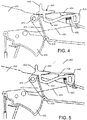
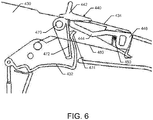
- FIGS. 4-6 illustrate partially cutaway views of the rear handle 430 to show various components in different conditions during a sequence of operations according to an example embodiment.
- FIG. 4 shows a structure that could be an example of the catch mechanism/clutch 224 of FIG. 1 (i.e., representing an example of a mechanical structure for embodying the interlock member 220).
- the throttle lockout member 434 may be on a top side of the rear handle 430 and the trigger 432 may be on the opposite side of the rear handle 430 (i.e., on the bottom).
- a single action such as grasping the rear handle 430 could actuate both the throttle lockout member 434 and the trigger 432.
- the catch 440 is provided to ensure that a dissimilar action (i.e., an enabling action) is required to be provided by the operator to unlock the throttle lockout member 434.
- FIG. 4 shows the catch 440 prior to the enabling action being performed.
- FIG. 5 illustrates the catch 440 after the enabling action has been performed.
- FIG. 6 illustrates the throttle lockout member 434 after the enabling action has been performed and the throttle lockout member 434 is in the actuated state.
- the catch 440 may include an operative member 442, a connecting portion 444 and a blocking portion 446.
- the operative member 442 may be a slidable member that can be slid forward to actuate the catch 440 or move the catch 440 to initiate the enabling action (i.e., pushing the operative member 442 and thereby the entire catch 440 forward with the thumb or another finger of the operator).
- the connecting portion 444 may be an elongate member that may connect the operative member 442 to the blocking portion 446. Meanwhile, the blocking portion 446 may extend from a portion of the throttle lockout member 434 to prevent movement of the throttle lockout member 434 to the actuated state unless the catch 440 is actuated (i.e., when the operative member 442 is pushed forward).
- a biasing element may be provided to bias the blocking portion 446 to be extended out of a rear end of the throttle lockout member 434.
- the spring 450 may bias the blocking portion 446 to prevent the throttle lockout member 434 from being depressed.
- the operative member 442 is pressed in the direction shown by arrow 460 (i.e., forward)
- the entire catch 440 moves in the direction of arrow 460 so that the blocking portion 446 is essentially withdrawn into the throttle lockout member 434 so that downward movement to actuate the throttle lockout member 434 is not inhibited as shown in FIG. 5 .
- the spring 450 is compressed to return the blocking portion 446 to its rest position as soon as the operator releases the operative member 442.
- the operator may depress or actuate the throttle lockout member 434 to transition the throttle lockout member 434 to the actuated state as shown in FIG. 6 .
- the trigger 432 may be cycled repeatedly on and off and there is no need to repeat the enabling action as long as the throttle lockout member 434 is maintained in the actuated state.
- the blocking portion 446 will extend rearward and resume blocking of any subsequent compression of the throttle lockout member 434 unless the enabling action (i.e., forward movement of the operative member 442) is also executed.
- compression of the throttle lockout member 434 may cause rotation of the throttle lockout member 434 about a pivot point 470 so that a pivot member 472 rotates forward to allow the trigger 432 to also be compressed as shown in FIG. 6 .
- the pivot member 472 When the pivot member 472 is in the position shown in FIG. 5 , the trigger 432 cannot be compressed as the pivot member 472 blocks a lockout interface portion 474 from moving upward.
- the lockout interface portion 474 is clear to move past the pivot member 472 to enable the trigger 432 to be actuated.
- a lockout biasing member e.g., spring 480
- the throttle lockout member 434 may return the throttle lockout member 434 to its rest position (i.e., not compressed or actuated).
- the spring 480 may also return the trigger 432 to its rest position when the trigger 432 is not being compressed by the operator.
- FIGS. 7-10 illustrate examples not according to the claims in which the keypad and switch 228 described in reference to FIG. 1 may be embodied in a chainsaw as one example of the tool 100.
- FIGS. 7 and 8 illustrate a chainsaw 500 having a keypad 510 via which the dissimilar action (i.e., the enabling action) can be provided.
- the operator in FIG. 7 performs one action (i.e., compressing a throttle lockout member 520).
- FIG. 7 performs one action (i.e., compressing a throttle lockout member 520).
- the operator reaches with the thumb to perform a dissimilar and enabling action of actuating a key on the keypad 510 to unlock the throttle lockout member 520.
- the physical position of the throttle lockout member 520 may be allowed to move to a compressed state whether or not the enabling action is performed. However, the throttle lockout member 520 may not be permitted to transition to the actuated state until both the throttle lockout member 520 is compressed and the enabling action is performed. In other cases, the throttle lockout member 520 may be physically inhibited from movement as well.
- the actuation of the trigger 530 may be repeatedly cycled without repeating the enabling action.
- An operator holding the rear handle 540 may therefore only perform the enabling action one time and, as long as the throttle lockout member 520 remains compressed thereafter, can repeatedly cycle the trigger 530.
- Whether the throttle lockout member 520 is compressed or not may be determinable via a switch 550 that may be provided in the handle 540.
- the switch 550 is open and a controller or other processing circuitry operably coupled to the keypad 510 to implement functionality of the interlock member 220 based on the operation of the keypad 510 and throttle lockout member 520 may be configured to indicate the throttle lockout member 520 as being in a not-actuated condition or state.
- the keypad 510 has been actuated to initiate the enabling action, when the throttle lockout member 520 is compressed as shown in FIG.
- the switch 550 is closed and the controller indicates that the throttle lockout member 520 is in the actuated state.
- the trigger 530 may then be repeatedly actuated (e.g., cycled on and off) as long as the controller indicates that the throttle lockout member 520 is in the actuated state.
- the controller may be configured to interface with the keypad 510 and/or the throttle lockout member 520 in a manner that only considers physical positions of components at the present time. For example, the enabling action may need to be performed on the keypad 510 while the throttle lockout member 520 is compressed to switch the throttle lockout member 520 to the actuated state.
- the controller may be configured to integrate timing considerations. For example, after the enabling action is performed on the keypad 510, a timer may pass timing information to the controller. The controller may allow the compression of the throttle lockout member 520 within a predetermined time after performance of the enabling action to shift the throttle lockout member 520 to the actuated state. Timing limitations may also be implemented, if desired, relative to switch activation and/or trigger activation in various ways in various embodiments.
- FIGS. 4 and 5 may be slightly modified in form, but may operate substantially the same from a functional perspective.
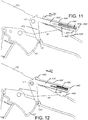
- An example of a slightly modified structure is provided in the examples of FIGS. 11 and 12 .
- FIGS. 11 and 12 illustrate partially cutaway views of the rear handle 430 to show various components in different conditions during a sequence of operations according to another example embodiment.
- FIG. 11 shows another structure that could be an example of the catch mechanism/clutch 224 of FIG. 1 (i.e., representing an example of a mechanical structure for embodying the interlock member 220).
- the throttle lockout member 434' may be on a top side of the rear handle 430 and the trigger 432 may be on the opposite side of the rear handle 430 (i.e., on the bottom).
- FIGS. 11 and 12 illustrate partially cutaway views of the rear handle 430 to show various components in different conditions during a sequence of operations according to another example embodiment.
- FIG. 11 shows another structure that could be an example of the catch mechanism/clutch 224 of FIG. 1 (i.e., representing an example of a mechanical structure for embodying the interlock member 220).
- the throttle lockout member 434' may be on a top side of the rear handle 430 and the trigger 432
- a single action such as grasping the rear handle 430 could actuate both the throttle lockout member 434' and the trigger 432.
- a catch 440' is provided to ensure that a dissimilar action (i.e., an enabling action) is required to be provided by the operator to unlock the throttle lockout member 434'.
- FIG. 11 shows the catch 440' prior to the enabling action being performed.
- FIG. 12 illustrates the catch 440' after the enabling action has been performed.
- the throttle lockout member 434' could be depressed (similar to FIG. 6 ) to allow the throttle 432 to be actuated while the throttle lockout member 434' is in the actuated state.
- the catch 440' may include an operative member 442', a connecting portion 444' and a blocking portion 446'.
- the operative member 442' may be a slidable member that can be slid forward to actuate the catch 440' or move the catch 440' to initiate the enabling action (i.e., pushing the operative member 442' and thereby the entire catch 440' forward with the thumb or another finger of the operator).
- the connecting portion 444' may be a portion that encases at least part of a body of the throttle lockout member 434'. However, a portion of the connecting portion 444' may also be inside the throttle lockout member 434'. In this regard, the connecting portion 444' may define a first cavity 445 and a second cavity 447 between which a portion of the connecting portion 444' may extend.
- the first cavity 445 may receive a protrusion 449 from the body of the throttle lockout member 434'.
- the second cavity 447 may house a biasing element (e.g., spring 450').
- the blocking portion 446' may extend from a rear portion of the throttle lockout member connecting portion 444' to prevent movement of the throttle lockout member 434' to the actuated state unless the catch 440' is actuated (i.e., when the operative member 442' is pushed forward in the direction of arrow 460).
- the biasing element e.g., spring 450'
- the biasing element may be provided to bias the connecting portion 444' (and thereby also the blocking portion 446') to be extended out of a rear end of the throttle lockout member 434'.
- the spring 450' may bias the blocking portion 446' to prevent the throttle lockout member 434' from being depressed.
- the entire catch 440' moves in the direction of arrow 460 so that the blocking portion 446' is essentially withdrawn toward (and to some degree farther into) the throttle lockout member 434' so that downward movement to actuate the throttle lockout member 434' is not inhibited as shown in FIG. 12 .
- the spring 450' is compressed to build up spring force to return the blocking portion 446' to its rest position as soon as the operator releases the operative member 442'.
- the catch mechanism 440' defines an exposed top surface extending continuously from the operative member 442' to the blocking member 446'.
- FIGS. 4 and 5 provide that the connecting portion 444 is substantially inside the throttle lockout member 434, in the examples of FIGS. 11 and 12 , only a small portion of the connecting portion 444' is within the throttle lockout member 434', while most of the connecting portion 444' actually surrounds a corresponding portion of the throttle lockout member 434'.
- Example embodiments may therefore provide a relatively easy way to improve the safety and operability of the power tool (e.g., the chainsaw, blower, edger, trimmer and/or the like).
- the power tool e.g., the chainsaw, blower, edger, trimmer and/or the like.
Landscapes
- Engineering & Computer Science (AREA)
- Mechanical Engineering (AREA)
- Life Sciences & Earth Sciences (AREA)
- General Engineering & Computer Science (AREA)
- Wood Science & Technology (AREA)
- Forests & Forestry (AREA)
- Harvester Elements (AREA)
- Portable Power Tools In General (AREA)
Claims (5)
- Steuerbaugruppe (140) für die selektive Steuerung der Betätigung eines Elektromotors (120), der eine Arbeitsbaugruppe (130) eines handgeführten Elektrowerkzeugs (100) antreibt, wobei die Steuerbaugruppe (140) so konfiguriert ist, dass sie die selektive Steuerung basierend auf der Ausführung von wenigstens zwei unterschiedlichen Bedieneraktionen bereitzustellen, wobei die Steuerbaugruppe (140) umfasst:ein Erfassungselement (210), das so konfiguriert ist, dass es als Reaktion auf eine Freigabeaktion, die eine erste der beiden unterschiedlichen Bedieneraktionen umfasst, in einen betätigten Zustand betrieben werden kann;ein Drosselsteuerelement (200), das so konfiguriert ist, dass es als Reaktion auf die Betätigung des Drosselsteuerelements (200) wiederholt betrieben werden kann, während sich das Erfassungselement (210) in dem betätigten Zustand befindet, und wobei die Betätigung des Drosselsteuerelements (200) eine zweite der zwei unterschiedlichen Bedieneraktionen umfasst; undeine Verriegelungsbaugruppe (220), die betriebsfähig mit dem Erfassungselement (210) gekoppelt ist, um eine Betätigung des Erfassungselements (210) zu verhindern, bis die Freigabeaktion durchgeführt wird;
wobeidas Erfassungselement (210) an einem ersten Abschnitt eines Griffs (430/540) des Werkzeugs (100) angeordnet ist und das Drosselsteuerelement (200) an einem zweiten Abschnitt des Griffs (430/540) angeordnet ist, wobei der erste und der zweite Abschnitt auf gegenüberliegenden Seiten des Griffs (430/540) liegen;wobei die zweite der zwei unterschiedlichen Aktionen mit einem Greifen des Griffs (430/540) verbunden ist; wobeidie erste der zwei unterschiedlichen Aktionen die Durchführung der Freigabeaktion unter Verwendung eines Fingers umfasst, um die Verriegelungsbaugruppe (220) unabhängig von einer Bewegung zum Ergreifen des Griffs (430/540) zu betätigen; und dadurch gekennzeichnet, dassdie Verriegelungsbaugruppe (220) einen Fangmechanismus (440, 440') umfasst, der wenigstens teilweise innerhalb eines Abschnitts des Erfassungselements (210) angeordnet ist. - Steuerbaugruppe (140) nach Anspruch 1, wobei die Verriegelungsanordnung (220) ferner so konfiguriert ist, dass sie ermöglicht, dass das Erfassungselement (210) von dem Bediener in dem betätigten Zustand gehalten werden kann, und wobei das Drosselsteuerelement (200) lösbar ist und ohne anschließende Durchführung der Freigabeaktion erneut betätigt werden kann.
- Steuerbaugruppe (140) nach Anspruch 1 oder 2, wobei der Fangmechanismus (440, 440') ein Betriebselement (442, 442') umfasst, das durch den Finger betätigt wird, um ein Blockierelement (446, 446') des Fangmechanismus (440, 440') aus einer Blockierposition zu drängen, um zu ermöglichen, dass das Erfassungselement (210) betätigt werden kann.
- Steuerbaugruppe (140) nach Anspruch 3, wobei das Blockierelement (446, 446') durch ein Vorspannungselement (450, 450') in Richtung der Blockierposition vorgespannt wird.
- Handgeführtes Elektrowerkzeug (100), das umfasst:eine elektrische Stromquelle (110);einen Elektromotor {120), der selektiv mit der elektrischen Stromquelle (110) gekoppelt ist;eine Arbeitsbaugruppe (130), die betriebsfähig mit dem Elektromotor (120) gekoppelt ist, um eine Arbeitsfunktion als Reaktion auf die Betätigung des Elektromotors (120) durchzuführen; undeine Steuerbaugruppe (140) nach einem der vorhergehenden Ansprüche, die betriebsfähig mit dem Elektromotor (120) gekoppelt ist, um eine selektive Steuerung über die Betätigung des Elektromotors (120) bereitzustellen.
Applications Claiming Priority (2)
| Application Number | Priority Date | Filing Date | Title |
|---|---|---|---|
| PCT/EP2014/059311 WO2015169350A1 (en) | 2014-05-07 | 2014-05-07 | Throttle lockout with dissimilar action |
| PCT/EP2015/059911 WO2015169828A1 (en) | 2014-05-07 | 2015-05-06 | Throttle lockout with dissimilar action |
Publications (2)
| Publication Number | Publication Date |
|---|---|
| EP3140082A1 EP3140082A1 (de) | 2017-03-15 |
| EP3140082B1 true EP3140082B1 (de) | 2021-07-07 |
Family
ID=50680038
Family Applications (1)
| Application Number | Title | Priority Date | Filing Date |
|---|---|---|---|
| EP15719485.3A Active EP3140082B1 (de) | 2014-05-07 | 2015-05-06 | Drosselsperre mit unterschiedlicher wirkung |
Country Status (4)
| Country | Link |
|---|---|
| US (2) | US10605406B2 (de) |
| EP (1) | EP3140082B1 (de) |
| CN (1) | CN106457547B (de) |
| WO (2) | WO2015169350A1 (de) |
Cited By (1)
| Publication number | Priority date | Publication date | Assignee | Title |
|---|---|---|---|---|
| EP4603229A1 (de) * | 2024-02-19 | 2025-08-20 | Yamabiko Corporation | Schalthebelmechanismus für eine elektrische handarbeitsmaschine |
Families Citing this family (8)
| Publication number | Priority date | Publication date | Assignee | Title |
|---|---|---|---|---|
| DE102011089719A1 (de) * | 2011-12-23 | 2013-06-27 | Robert Bosch Gmbh | Elektrisch betreibbare Werkzeugmaschine |
| EP3673199B1 (de) * | 2017-09-27 | 2023-06-07 | Globe (Jiangsu) Co., Ltd. | Auslösersperre mit unterschiedlichen wirkungen |
| JP7049946B2 (ja) | 2018-06-28 | 2022-04-07 | 株式会社マキタ | ベルトサンダ |
| JP7156842B2 (ja) * | 2018-07-17 | 2022-10-19 | 株式会社やまびこ | 手持式作業機 |
| DE102020209908A1 (de) * | 2020-08-05 | 2022-02-10 | Robert Bosch Gesellschaft mit beschränkter Haftung | Sicherheitsbedienvorrichtung und Werkzeugmaschinensystem mit der Sicherheitsbedienvorrichtung |
| US12064894B2 (en) * | 2020-09-04 | 2024-08-20 | Milwaukee Electric Tool Corporation | Chainsaw |
| TWI745198B (zh) * | 2020-12-21 | 2021-11-01 | 力山工業股份有限公司 | 具安全裝置的可收合鋸切機 |
| JP7584863B2 (ja) * | 2021-02-16 | 2024-11-18 | 株式会社やまびこ | 駆動装置 |
Family Cites Families (17)
| Publication number | Priority date | Publication date | Assignee | Title |
|---|---|---|---|---|
| SE515430C2 (sv) * | 1999-12-02 | 2001-08-06 | Electrolux Ab | Bromsutlösningsanordning för handhållet arbetsredskap |
| US20020185514A1 (en) * | 2000-12-22 | 2002-12-12 | Shane Adams | Control module for flywheel operated hand tool |
| US6575285B2 (en) * | 2001-11-14 | 2003-06-10 | Jenn Feng Industrial Co., Ltd. | Safety switch for power tools |
| US6698566B2 (en) * | 2001-11-14 | 2004-03-02 | Jenn Feng Industrial Co., Ltd. | Clutch type safety switch for power tools |
| US6878888B1 (en) * | 2004-03-24 | 2005-04-12 | Jenn Peng Industrial Co., Ltd. | Safety device for activating electric tools |
| US7213732B2 (en) * | 2004-04-02 | 2007-05-08 | Black & Decker Inc. | Contact trip mechanism for nailer |
| DE602006012486D1 (de) * | 2005-06-13 | 2010-04-08 | Yamabiko Corp | Kraftbetriebenes handwerkzeug |
| CN101802380B (zh) | 2007-09-21 | 2012-10-10 | 胡斯华纳有限公司 | 用于手持式动力工具的怠速控制方法 |
| DE102009012181A1 (de) * | 2009-02-27 | 2010-09-02 | Andreas Stihl Ag & Co. Kg | Akkubetriebenes, handgeführtes Arbeitsgerät mit einem Gashebel |
| WO2010115438A1 (en) * | 2009-04-08 | 2010-10-14 | Husqvarna Ab | Battery-powered portable tools |
| DE102009054927B4 (de) * | 2009-12-18 | 2025-12-18 | Robert Bosch Gmbh | Handwerkzeugmaschine, insbesondere Akkuhandwerkzeugmaschine |
| JP5767791B2 (ja) * | 2010-08-24 | 2015-08-19 | 株式会社マキタ | 手持ち式動力作業機 |
| US9421682B2 (en) | 2011-07-18 | 2016-08-23 | Black & Decker Inc. | Multi-head power tool with reverse lock-out capability |
| CN202194729U (zh) | 2011-08-05 | 2012-04-18 | 江苏东俪动力机械制造有限公司 | 园林机械的旋转式油门操作手柄 |
| WO2013032374A1 (en) * | 2011-08-26 | 2013-03-07 | Husqvarna Ab | Guide and control assembly |
| DE102012025309A1 (de) * | 2012-12-22 | 2014-06-26 | Andreas Stihl Ag & Co. Kg | Handgeführtes Arbeitsgerät mit einem Antriebsmotor zum Antrieb mindestens eines Werkzeugs und Verfahren zu dessen Betrieb |
| JP2015200195A (ja) * | 2014-04-04 | 2015-11-12 | 株式会社マキタ | 作業機 |
-
2014
- 2014-05-07 WO PCT/EP2014/059311 patent/WO2015169350A1/en not_active Ceased
-
2015
- 2015-05-06 EP EP15719485.3A patent/EP3140082B1/de active Active
- 2015-05-06 US US15/308,440 patent/US10605406B2/en active Active
- 2015-05-06 WO PCT/EP2015/059911 patent/WO2015169828A1/en not_active Ceased
- 2015-05-06 CN CN201580023795.0A patent/CN106457547B/zh active Active
-
2020
- 2020-02-13 US US16/790,018 patent/US11015760B2/en active Active
Non-Patent Citations (1)
| Title |
|---|
| None * |
Cited By (2)
| Publication number | Priority date | Publication date | Assignee | Title |
|---|---|---|---|---|
| EP4603229A1 (de) * | 2024-02-19 | 2025-08-20 | Yamabiko Corporation | Schalthebelmechanismus für eine elektrische handarbeitsmaschine |
| US12594661B2 (en) | 2024-02-19 | 2026-04-07 | Yamabiko Corporation | Operating lever mechanism for electric handheld working machine |
Also Published As
| Publication number | Publication date |
|---|---|
| WO2015169350A1 (en) | 2015-11-12 |
| EP3140082A1 (de) | 2017-03-15 |
| CN106457547A (zh) | 2017-02-22 |
| US11015760B2 (en) | 2021-05-25 |
| WO2015169828A1 (en) | 2015-11-12 |
| US10605406B2 (en) | 2020-03-31 |
| CN106457547B (zh) | 2020-05-01 |
| US20170051873A1 (en) | 2017-02-23 |
| US20200182402A1 (en) | 2020-06-11 |
Similar Documents
| Publication | Publication Date | Title |
|---|---|---|
| US11015760B2 (en) | Throttle lockout with dissimilar action | |
| EP2794193B1 (de) | Verfahren und mechanismus für die sperre eines maschinenwerkzeugs | |
| KR101777763B1 (ko) | 방아쇠로 작동하는 휴대용 전동 공구 | |
| US5969312A (en) | Ambidextrous powers-switch lock-out mechanism | |
| US4122320A (en) | Hand-operated double-acting trigger switch | |
| EP2606717A1 (de) | Vorrichtung zum Scheiden von Vegetation | |
| US20180093335A1 (en) | Trigger lock for a miter saw | |
| CN101658105B (zh) | 开关操作机构 | |
| CN106514568B (zh) | 用于起动带有电动机的手引导式工作器械的方法 | |
| EP3944275B1 (de) | Schalteranordnung, verfahren zur steuerung einer schalteranordnung und werkzeugmaschine | |
| EP3141357B1 (de) | Elektrische schere | |
| EP3673199B1 (de) | Auslösersperre mit unterschiedlichen wirkungen | |
| EP3974110B1 (de) | Schalteranordnung und kraftwerkzeug | |
| CN110125882B (zh) | 用于电驱动式园林工具的开关装置 | |
| US6878888B1 (en) | Safety device for activating electric tools | |
| US9085087B2 (en) | Palm jig saw | |
| CN112912213B (zh) | 操纵单元 | |
| CN121282040A (zh) | 工具机和工具机的开关单元 | |
| CA1110298A (en) | Actuator mechanism for a portable hand-held tool |
Legal Events
| Date | Code | Title | Description |
|---|---|---|---|
| STAA | Information on the status of an ep patent application or granted ep patent |
Free format text: STATUS: THE INTERNATIONAL PUBLICATION HAS BEEN MADE |
|
| PUAI | Public reference made under article 153(3) epc to a published international application that has entered the european phase |
Free format text: ORIGINAL CODE: 0009012 |
|
| STAA | Information on the status of an ep patent application or granted ep patent |
Free format text: STATUS: REQUEST FOR EXAMINATION WAS MADE |
|
| 17P | Request for examination filed |
Effective date: 20161124 |
|
| AK | Designated contracting states |
Kind code of ref document: A1 Designated state(s): AL AT BE BG CH CY CZ DE DK EE ES FI FR GB GR HR HU IE IS IT LI LT LU LV MC MK MT NL NO PL PT RO RS SE SI SK SM TR |
|
| AX | Request for extension of the european patent |
Extension state: BA ME |
|
| DAV | Request for validation of the european patent (deleted) | ||
| DAX | Request for extension of the european patent (deleted) | ||
| STAA | Information on the status of an ep patent application or granted ep patent |
Free format text: STATUS: EXAMINATION IS IN PROGRESS |
|
| 17Q | First examination report despatched |
Effective date: 20200811 |
|
| GRAP | Despatch of communication of intention to grant a patent |
Free format text: ORIGINAL CODE: EPIDOSNIGR1 |
|
| STAA | Information on the status of an ep patent application or granted ep patent |
Free format text: STATUS: GRANT OF PATENT IS INTENDED |
|
| INTG | Intention to grant announced |
Effective date: 20210401 |
|
| GRAS | Grant fee paid |
Free format text: ORIGINAL CODE: EPIDOSNIGR3 |
|
| GRAA | (expected) grant |
Free format text: ORIGINAL CODE: 0009210 |
|
| STAA | Information on the status of an ep patent application or granted ep patent |
Free format text: STATUS: THE PATENT HAS BEEN GRANTED |
|
| AK | Designated contracting states |
Kind code of ref document: B1 Designated state(s): AL AT BE BG CH CY CZ DE DK EE ES FI FR GB GR HR HU IE IS IT LI LT LU LV MC MK MT NL NO PL PT RO RS SE SI SK SM TR |
|
| REG | Reference to a national code |
Ref country code: GB Ref legal event code: FG4D |
|
| REG | Reference to a national code |
Ref country code: AT Ref legal event code: REF Ref document number: 1408092 Country of ref document: AT Kind code of ref document: T Effective date: 20210715 |
|
| REG | Reference to a national code |
Ref country code: DE Ref legal event code: R096 Ref document number: 602015071068 Country of ref document: DE |
|
| REG | Reference to a national code |
Ref country code: IE Ref legal event code: FG4D |
|
| REG | Reference to a national code |
Ref country code: LT Ref legal event code: MG9D |
|
| REG | Reference to a national code |
Ref country code: NL Ref legal event code: MP Effective date: 20210707 |
|
| REG | Reference to a national code |
Ref country code: AT Ref legal event code: MK05 Ref document number: 1408092 Country of ref document: AT Kind code of ref document: T Effective date: 20210707 |
|
| PG25 | Lapsed in a contracting state [announced via postgrant information from national office to epo] |
Ref country code: HR Free format text: LAPSE BECAUSE OF FAILURE TO SUBMIT A TRANSLATION OF THE DESCRIPTION OR TO PAY THE FEE WITHIN THE PRESCRIBED TIME-LIMIT Effective date: 20210707 Ref country code: RS Free format text: LAPSE BECAUSE OF FAILURE TO SUBMIT A TRANSLATION OF THE DESCRIPTION OR TO PAY THE FEE WITHIN THE PRESCRIBED TIME-LIMIT Effective date: 20210707 Ref country code: SE Free format text: LAPSE BECAUSE OF FAILURE TO SUBMIT A TRANSLATION OF THE DESCRIPTION OR TO PAY THE FEE WITHIN THE PRESCRIBED TIME-LIMIT Effective date: 20210707 Ref country code: NO Free format text: LAPSE BECAUSE OF FAILURE TO SUBMIT A TRANSLATION OF THE DESCRIPTION OR TO PAY THE FEE WITHIN THE PRESCRIBED TIME-LIMIT Effective date: 20211007 Ref country code: NL Free format text: LAPSE BECAUSE OF FAILURE TO SUBMIT A TRANSLATION OF THE DESCRIPTION OR TO PAY THE FEE WITHIN THE PRESCRIBED TIME-LIMIT Effective date: 20210707 Ref country code: PT Free format text: LAPSE BECAUSE OF FAILURE TO SUBMIT A TRANSLATION OF THE DESCRIPTION OR TO PAY THE FEE WITHIN THE PRESCRIBED TIME-LIMIT Effective date: 20211108 Ref country code: FI Free format text: LAPSE BECAUSE OF FAILURE TO SUBMIT A TRANSLATION OF THE DESCRIPTION OR TO PAY THE FEE WITHIN THE PRESCRIBED TIME-LIMIT Effective date: 20210707 Ref country code: ES Free format text: LAPSE BECAUSE OF FAILURE TO SUBMIT A TRANSLATION OF THE DESCRIPTION OR TO PAY THE FEE WITHIN THE PRESCRIBED TIME-LIMIT Effective date: 20210707 Ref country code: BG Free format text: LAPSE BECAUSE OF FAILURE TO SUBMIT A TRANSLATION OF THE DESCRIPTION OR TO PAY THE FEE WITHIN THE PRESCRIBED TIME-LIMIT Effective date: 20211007 Ref country code: AT Free format text: LAPSE BECAUSE OF FAILURE TO SUBMIT A TRANSLATION OF THE DESCRIPTION OR TO PAY THE FEE WITHIN THE PRESCRIBED TIME-LIMIT Effective date: 20210707 Ref country code: LT Free format text: LAPSE BECAUSE OF FAILURE TO SUBMIT A TRANSLATION OF THE DESCRIPTION OR TO PAY THE FEE WITHIN THE PRESCRIBED TIME-LIMIT Effective date: 20210707 |
|
| PG25 | Lapsed in a contracting state [announced via postgrant information from national office to epo] |
Ref country code: PL Free format text: LAPSE BECAUSE OF FAILURE TO SUBMIT A TRANSLATION OF THE DESCRIPTION OR TO PAY THE FEE WITHIN THE PRESCRIBED TIME-LIMIT Effective date: 20210707 Ref country code: LV Free format text: LAPSE BECAUSE OF FAILURE TO SUBMIT A TRANSLATION OF THE DESCRIPTION OR TO PAY THE FEE WITHIN THE PRESCRIBED TIME-LIMIT Effective date: 20210707 Ref country code: GR Free format text: LAPSE BECAUSE OF FAILURE TO SUBMIT A TRANSLATION OF THE DESCRIPTION OR TO PAY THE FEE WITHIN THE PRESCRIBED TIME-LIMIT Effective date: 20211008 |
|
| REG | Reference to a national code |
Ref country code: DE Ref legal event code: R097 Ref document number: 602015071068 Country of ref document: DE |
|
| PG25 | Lapsed in a contracting state [announced via postgrant information from national office to epo] |
Ref country code: DK Free format text: LAPSE BECAUSE OF FAILURE TO SUBMIT A TRANSLATION OF THE DESCRIPTION OR TO PAY THE FEE WITHIN THE PRESCRIBED TIME-LIMIT Effective date: 20210707 |
|
| PLBE | No opposition filed within time limit |
Free format text: ORIGINAL CODE: 0009261 |
|
| STAA | Information on the status of an ep patent application or granted ep patent |
Free format text: STATUS: NO OPPOSITION FILED WITHIN TIME LIMIT |
|
| PG25 | Lapsed in a contracting state [announced via postgrant information from national office to epo] |
Ref country code: SM Free format text: LAPSE BECAUSE OF FAILURE TO SUBMIT A TRANSLATION OF THE DESCRIPTION OR TO PAY THE FEE WITHIN THE PRESCRIBED TIME-LIMIT Effective date: 20210707 Ref country code: SK Free format text: LAPSE BECAUSE OF FAILURE TO SUBMIT A TRANSLATION OF THE DESCRIPTION OR TO PAY THE FEE WITHIN THE PRESCRIBED TIME-LIMIT Effective date: 20210707 Ref country code: RO Free format text: LAPSE BECAUSE OF FAILURE TO SUBMIT A TRANSLATION OF THE DESCRIPTION OR TO PAY THE FEE WITHIN THE PRESCRIBED TIME-LIMIT Effective date: 20210707 Ref country code: EE Free format text: LAPSE BECAUSE OF FAILURE TO SUBMIT A TRANSLATION OF THE DESCRIPTION OR TO PAY THE FEE WITHIN THE PRESCRIBED TIME-LIMIT Effective date: 20210707 Ref country code: CZ Free format text: LAPSE BECAUSE OF FAILURE TO SUBMIT A TRANSLATION OF THE DESCRIPTION OR TO PAY THE FEE WITHIN THE PRESCRIBED TIME-LIMIT Effective date: 20210707 Ref country code: AL Free format text: LAPSE BECAUSE OF FAILURE TO SUBMIT A TRANSLATION OF THE DESCRIPTION OR TO PAY THE FEE WITHIN THE PRESCRIBED TIME-LIMIT Effective date: 20210707 |
|
| 26N | No opposition filed |
Effective date: 20220408 |
|
| PG25 | Lapsed in a contracting state [announced via postgrant information from national office to epo] |
Ref country code: IT Free format text: LAPSE BECAUSE OF FAILURE TO SUBMIT A TRANSLATION OF THE DESCRIPTION OR TO PAY THE FEE WITHIN THE PRESCRIBED TIME-LIMIT Effective date: 20210707 |
|
| REG | Reference to a national code |
Ref country code: CH Ref legal event code: PL |
|
| REG | Reference to a national code |
Ref country code: BE Ref legal event code: MM Effective date: 20220531 |
|
| GBPC | Gb: european patent ceased through non-payment of renewal fee |
Effective date: 20220506 |
|
| PG25 | Lapsed in a contracting state [announced via postgrant information from national office to epo] |
Ref country code: MC Free format text: LAPSE BECAUSE OF FAILURE TO SUBMIT A TRANSLATION OF THE DESCRIPTION OR TO PAY THE FEE WITHIN THE PRESCRIBED TIME-LIMIT Effective date: 20210707 Ref country code: LU Free format text: LAPSE BECAUSE OF NON-PAYMENT OF DUE FEES Effective date: 20220506 Ref country code: LI Free format text: LAPSE BECAUSE OF NON-PAYMENT OF DUE FEES Effective date: 20220531 Ref country code: CH Free format text: LAPSE BECAUSE OF NON-PAYMENT OF DUE FEES Effective date: 20220531 |
|
| PG25 | Lapsed in a contracting state [announced via postgrant information from national office to epo] |
Ref country code: IE Free format text: LAPSE BECAUSE OF NON-PAYMENT OF DUE FEES Effective date: 20220506 Ref country code: FR Free format text: LAPSE BECAUSE OF NON-PAYMENT OF DUE FEES Effective date: 20220531 |
|
| PG25 | Lapsed in a contracting state [announced via postgrant information from national office to epo] |
Ref country code: GB Free format text: LAPSE BECAUSE OF NON-PAYMENT OF DUE FEES Effective date: 20220506 Ref country code: BE Free format text: LAPSE BECAUSE OF NON-PAYMENT OF DUE FEES Effective date: 20220531 |
|
| P01 | Opt-out of the competence of the unified patent court (upc) registered |
Effective date: 20230419 |
|
| PG25 | Lapsed in a contracting state [announced via postgrant information from national office to epo] |
Ref country code: HU Free format text: LAPSE BECAUSE OF FAILURE TO SUBMIT A TRANSLATION OF THE DESCRIPTION OR TO PAY THE FEE WITHIN THE PRESCRIBED TIME-LIMIT; INVALID AB INITIO Effective date: 20150506 |
|
| PG25 | Lapsed in a contracting state [announced via postgrant information from national office to epo] |
Ref country code: MK Free format text: LAPSE BECAUSE OF FAILURE TO SUBMIT A TRANSLATION OF THE DESCRIPTION OR TO PAY THE FEE WITHIN THE PRESCRIBED TIME-LIMIT Effective date: 20210707 Ref country code: CY Free format text: LAPSE BECAUSE OF FAILURE TO SUBMIT A TRANSLATION OF THE DESCRIPTION OR TO PAY THE FEE WITHIN THE PRESCRIBED TIME-LIMIT Effective date: 20210707 |
|
| PG25 | Lapsed in a contracting state [announced via postgrant information from national office to epo] |
Ref country code: MT Free format text: LAPSE BECAUSE OF FAILURE TO SUBMIT A TRANSLATION OF THE DESCRIPTION OR TO PAY THE FEE WITHIN THE PRESCRIBED TIME-LIMIT Effective date: 20210707 |
|
| PGFP | Annual fee paid to national office [announced via postgrant information from national office to epo] |
Ref country code: DE Payment date: 20250409 Year of fee payment: 11 |
|
| PG25 | Lapsed in a contracting state [announced via postgrant information from national office to epo] |
Ref country code: TR Free format text: LAPSE BECAUSE OF FAILURE TO SUBMIT A TRANSLATION OF THE DESCRIPTION OR TO PAY THE FEE WITHIN THE PRESCRIBED TIME-LIMIT Effective date: 20210707 |