EP3140104B1 - Verfahren zur erzeugung von vorformlingen durch aufbringen und formen ausgerichteter fasern - Google Patents
Verfahren zur erzeugung von vorformlingen durch aufbringen und formen ausgerichteter fasern Download PDFInfo
- Publication number
- EP3140104B1 EP3140104B1 EP15721762.1A EP15721762A EP3140104B1 EP 3140104 B1 EP3140104 B1 EP 3140104B1 EP 15721762 A EP15721762 A EP 15721762A EP 3140104 B1 EP3140104 B1 EP 3140104B1
- Authority
- EP
- European Patent Office
- Prior art keywords
- plies
- fibres
- application
- fibers
- forming
- Prior art date
- Legal status (The legal status is an assumption and is not a legal conclusion. Google has not performed a legal analysis and makes no representation as to the accuracy of the status listed.)
- Active
Links
Images



Classifications
-
- B—PERFORMING OPERATIONS; TRANSPORTING
- B29—WORKING OF PLASTICS; WORKING OF SUBSTANCES IN A PLASTIC STATE IN GENERAL
- B29C—SHAPING OR JOINING OF PLASTICS; SHAPING OF MATERIAL IN A PLASTIC STATE, NOT OTHERWISE PROVIDED FOR; AFTER-TREATMENT OF THE SHAPED PRODUCTS, e.g. REPAIRING
- B29C70/00—Shaping composites, i.e. plastics material comprising reinforcements, fillers or preformed parts, e.g. inserts
- B29C70/04—Shaping composites, i.e. plastics material comprising reinforcements, fillers or preformed parts, e.g. inserts comprising reinforcements only, e.g. self-reinforcing plastics
- B29C70/06—Fibrous reinforcements only
- B29C70/10—Fibrous reinforcements only characterised by the structure of fibrous reinforcements, e.g. hollow fibres
- B29C70/16—Fibrous reinforcements only characterised by the structure of fibrous reinforcements, e.g. hollow fibres using fibres of substantial or continuous length
- B29C70/20—Fibrous reinforcements only characterised by the structure of fibrous reinforcements, e.g. hollow fibres using fibres of substantial or continuous length oriented in a single direction, e.g. roofing or other parallel fibres
- B29C70/205—Fibrous reinforcements only characterised by the structure of fibrous reinforcements, e.g. hollow fibres using fibres of substantial or continuous length oriented in a single direction, e.g. roofing or other parallel fibres the structure being shaped to form a three-dimensional configuration
-
- B—PERFORMING OPERATIONS; TRANSPORTING
- B29—WORKING OF PLASTICS; WORKING OF SUBSTANCES IN A PLASTIC STATE IN GENERAL
- B29B—PREPARATION OR PRETREATMENT OF THE MATERIAL TO BE SHAPED; MAKING GRANULES OR PREFORMS; RECOVERY OF PLASTICS OR OTHER CONSTITUENTS OF WASTE MATERIAL CONTAINING PLASTICS
- B29B11/00—Making preforms
- B29B11/14—Making preforms characterised by structure or composition
- B29B11/16—Making preforms characterised by structure or composition comprising fillers or reinforcement
Definitions
- the present invention relates to a method for producing preforms by applying fibers to a tool.
- the preform is obtained after cooling and demolding.
- This preform can then be subjected to an infusion or resin injection operation to obtain a final part made of composite material, comprising fibers and a resin matrix.
- This process is conventionally used for the manufacture of a preform from glass fibers.
- This fiber projection technique ensures good rates for the production of preforms.
- a drawback of this technique is the low mechanical strength of the final part due to the short fibers that are not oriented with respect to the main stresses, the short fibers being sprayed randomly. This technique cannot be used for the manufacture of structural parts.
- fiber placement methods are also known in which continuous fibers are deposited in contact on a tool to form several folds in defined orientations.
- This contact application method is implemented by means of a fiber application head comprising an application roller intended to come into contact against the tool to apply a strip formed of one or more continuous flat fibers. , and a guide system for guiding the fiber or fibers on said roll.
- the fibers applied can be continuous flat fibers, of the wicking type, dry or impregnated with thermosetting or thermoplastic resin, in particular carbon fibers, consisting of a multitude of carbon threads or filaments.
- WO 2012 / 045969A1 discloses a method for producing three-dimensional preforms according to the preamble of claim 1.
- the aim of the present invention is to provide a solution aimed at overcoming the aforementioned drawbacks.
- the present invention provides a method according to claim 1 for producing three-dimensional preforms.
- folds are made in the same orientation with partial overlap.
- the fibers of said plies move relative to each other so that the preform can be formed to its final shape without excessive stress exerted on the plies. fibers, and therefore without excessive deformation of the fibers.
- the process according to the invention allows the forming of complex three-dimensional parts, with oriented fibers, while limiting the phenomena of wrinkling of the fibers during forming.
- This principle of folds of the same orientation with partial overlap is carried out for the orientations and in the zones in which the fibers are subjected to significant longitudinal forces during forming.
- the fibers concerned by these elongation requirements are generally continuous fibers according to the main forces, and therefore going from one end of the preform to the other.
- the two folds of the same orientation are produced successively, said application of fibers comprising the production of at least two successive folds in the same orientation, the two folds being directly superimposed.
- said application of fibers comprises making at least two plies in the same orientation by inserting one or more plies of different orientations between the two said plies.
- the fibers of the two plies are superimposed on a first length, so that after forming, said fibers remain superimposed at the end on a second length less than the first length .
- This superposition at the end after forming makes it possible to guarantee continuity in the transmission of forces in the orientation in question and therefore better resistance of the part in said orientation.
- the application of fibers is automated and carried out by means of a fiber application head, by relative displacement of the application head with respect to the layup surface along different paths.
- the application step comprises the placement of fibers by means of a fiber placement head, known per se, making it possible to drape in contact, by means of a compacting roller, a strip formed. of one or more fibers.
- the application step comprises the non-contact application of fibers by means of an application head.
- the method comprises, before forming, locking the set of folds in order to lock in position the first or second folds of each pair of folds of the same orientation, so that during forming only the second or unblocked first folds of each pair of folds move longitudinally.
- the method includes applying multiple plies of fibers to a substantially planar application surface, transferring the set of plies to a press, and forming the set of plies between the plies.
- male forming tooling and female forming tooling of said press As a variant, the fibers are applied directly to a draping tool constituting the male or female forming tool of the press.
- the method may comprise the application of dry fibers provided with a binder, and / or the application of fibers pre-impregnated with one or more so-called impregnation resins, and / or the application of dry fibers and the application of a binder and / or impregnation resin on the application surface and / or the fibers already applied simultaneously and / or subsequently to the application of the fibers.
- the binder and / or the impregnating resin allows the adhesion of the fibers applied to the application surface and / or the fibers previously applied and thus ensures the cohesion of the preform.
- the binder and / or the impregnation resin are heated during the application of the fibers to allow said adhesion.
- the forming is preferably carried out hot, in order to heat the binder and / or the resin (s) in order to ensure better cohesion of the final preform and to facilitate the relative movement of the fibers with respect to each other during forming, in particular at their overlapping end portions. According to another embodiment, the forming is carried out without heating.
- the method according to the invention is a method for producing dry preforms, comprising less than 10% by weight of binder, preferably less than 5% by weight of binder, said dry preform subsequently being subjected to an operation impregnation with a resin to form a composite part.
- the dry preforms with binder comprise a small amount of binder, generally less than 5%, making it possible to maintain the cohesion of the preform, while allowing its subsequent impregnation.
- the dry preforms are obtained by applying dry fibers provided with a binder and / or by applying dry fibers, without a binder, and applying a binder to the application surface and / or the dry fibers.
- Said application of binder preferably comprises the spraying of a liquid binder and / or the projection of a binder in powder form, said binder allowing the adhesion of the fibers applied to the application surface and / or the fibers previously applied. .
- the method is a method for producing pre-impregnated type preforms, comprising at least 30% by weight of one or more thermoplastic and / or thermosetting resins, called impregnation, preferably at least 40% by weight, the said resin (s) constituting the matrix of the final composite part, the pre-impregnated preform not subsequently being subjected to an impregnation operation, for a core impregnation of the resins in the fibers, then an operation hardening.
- the prepreg preforms are obtained by applying prepreg fibers and / or by applying dry fibers and applying one or more resins to the application surface and / or the dry fibers.
- the method comprises a step of defining the zones in which fibers of a given orientation are subjected to significant forces during forming, via forming simulation software, and a step of defining trajectories for the forming. production of the folds comprising folds of the same orientation partially superimposed in said zones, the application of fibers being carried out from this definition of trajectories.
- the present invention also relates to a method of manufacturing parts made of composite material, characterized in that it comprises the production of a preform as described above, a step of impregnating resin in the preform, said step of impregnation comprising adding one or more impregnation resins by infusion or injection of the dry preform, or heating the pre-impregnated preform to impregnate the whole of the preform, the resin (s) forming the binder, and a curing step.
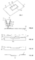
- the figure 1 illustrates an example of a preform 1 which can be produced according to the method according to the invention, by draping continuous fibers and forming.
- the preform is in the form of a substantially planar plate provided with a rectangular central protuberance or boss 12 on one main face, said boss forming a corresponding indentation on the other main face of the plate.
- the protuberance 12 has a flat bottom wall 121 connected to the flat part 11 of the plate by four inclined side walls 122 forming a ramp.
- the figures 2A to 2D illustrate the steps of the process for making this preform 1.
- folds are draped flat on a draping tool 2 in different orientations, for example at 0 °, 90 °, + 45 ° and -45 ° , by making two successive folds in the same orientation, as described below.
- the layup is carried out by means of a fiber placement head 3, known per se, allowing automatic layup in contact with strips formed from one or more fibers.
- the fibers F enter the head 3 in the form of two layers of fibers, and the head comprises a guide system 31 making it possible to guide the fibers towards the compacting roller in the form of a band of fibers in which the fibers are arranged side by side, for example substantially edge to edge.
- the head comprises, on either side of the main guiding system, cutting means 33 for individually cutting each fiber passing through the guiding system, locking means 34 arranged upstream of the cutting means with respect to the direction advancement of the fibers, to block each fiber which has just been cut, and re-routing or driving means 35 arranged upstream of the cutting means, to drive each fiber individually, in order to be able at any time to stop and resume the application of a fiber, as well as choosing the width of the strip.
- the draping of a strip is carried out by relative displacement of the head with respect to the substantially planar draping surface of the tool.
- the head comprises for example a support structure (not shown) on which is mounted the main guide system and by which the head can be assembled to a displacement system, capable of moving the head in at least two directions perpendicular to each other. the other.
- the head is fixed and the mold is able to be moved relative to the head to perform the draping operations.
- the head is for example designed to receive eight fibers, and allow the application of strips of 1 to 8 fibers 6.35 mm (1/4 inch) wide.
- the head is used for producing a dry preform, from dry fibers provided with a binder conventionally called a “binder”, to give the fibers a tackiness during draping.
- the binder is in the form of powder and / or one or more webs.
- the fibers are, for example, carbon fibers, continuous flat, of the wick type, comprising a multitude of carbon threads or filaments, with a thermoplastic binder in powder form, present in an amount of the order of 2% by weight. .
- the set E1 of folds is transferred to a press for the forming operation.
- the press comprises a female forming tool 41, having a recess, the shape of which corresponds to that of the boss 12 of the preform to be produced, and a male forming tool 42 comprising a boss 42a of complementary shape.
- the set E1 of folds is here transferred to the female forming tool 41. This transfer is for example carried out automatically, for example by means of a robot equipped with a gripper.
- the forming is carried out by relative bringing together of the male draping tool and the female molding tool, as illustrated in figure 2C .
- This compaction is preferably carried out hot, by heating the two tools 41, 42, in order to soften the binder and obtain a preform.
- the compaction is carried out using a vacuum bag system, for example in combination with the aforementioned female forming tool.
- the tools are then separated from one another in order to be able to unmold the preform 1 from the press.
- the demolded preform as illustrated on 2D figure , is then subjected to an operation of adding resin by injection and / or infusion to finally obtain a part made of composite material.
- the draping comprises the draping of plies in different orientations by draping pairs of plies in the same direction with partial covering of the fibers, in order to allow sliding of the fibers during forming and thus facilitate the operation. forming.
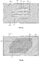
- the figures 3A and 3B illustrate the draping of two successive folds at 0 °.
- the first fold 5 at 90 ° is made by moving the head along parallel depositing paths, seven in number here, and referenced from T1 1 to T1 7 , to deposit a strip of 8 fibers at each path.
- the broken lines correspond to the projection of the ramps of the boss of the preform to be produced, more precisely to the junction line 91 between the bottom wall and the ramp, and the junction line 92 between the ramp and the flat part.
- the fibers of this first ply are intended to form the flat part 11 of the preform 1, and stop before the ramps of the boss of the final preform.
- continuous bands 51, 52 are deposited from one transverse edge 22 to the other 23 of the tool.
- a first segment 53a of strip and a second segment 53b of strip are deposited on either side of the junction line 92.
- the first segment 53a extends from the transverse edge 22 and s 'interrupts before the junction line 92.
- the so-called inner cutting edges 71 of the fibers of this first segment 53a and of this second segment 53b will be arranged at the level of the junction line 92 between the ramp and the flat part, or at a distance of this junction line, as illustrated on the figure 3A .
- These two tape segments are draped into a single head path, on the fly, cutting and locking the fibers through the cutting means and the placement head locking means to form the first segment, and releasing the fibers.
- first and second segments 54a, 55a, 54b, 55b of bands are draped on either side of the junction line during the fourth and fifth trajectories T1 4 , T1 5 .
- bands 56, 57 continuous in a single segment are deposited from one edge transverse to the other of the tool.
- the second 0 ° fold 6 is made by moving the head 3 along parallel depositing paths T2 1 , T2 2 , T2 3 , three in number here, to deposit a strip 61, 62, 63 of eight at each path fibers.
- the fibers of this second ply are intended to form the boss of the preform and extend beyond the ramps to partially cover the first and second segments of strips of the first ply.
- the three trajectories of the head for this second ply 6 are substantially coincident with the third, fourth and fifth trajectories of the head for the first ply 5.
- each strip 61, 62, 63 deposited begins before the inner edge 71 of the first segments 53a, 54a, 55a and extends beyond the interior edges 72 (shown in broken lines on the figure 3B ) second segments 53b, 54b, 55b, so that end portions of the bands 61, 62, 63 of this second ply cover end portions of the first and second segments over lengths L 1 , called overlap or overlap, defined between the edges 73, 74 of fibers of the bands of the second ply and the inner edges 71, 72 of the first and second segments.
- a plurality of pairs of pleats are draped in different orientations in the desired sequence. Pairs of -45 ° pleats are draped as described above for + 45 ° pleats.
- the overlap lengths and / or the positioning of the overlap zones are advantageously varied from one pair to another so as to limit the creation of significant excess thicknesses at the level of the zones. recovery. Furthermore, intermediate folds outside the overlap zones can be provided.
- the head 3 is here equipped with a heating system in order to heat the binder during application of the fibers, and thus allow adhesion of the fibers of the various plies and ensure the cohesion of the set E1 of plies for its subsequent transfer.
- the heating system for example of the IR lamp type, heats the fibers before their application to the application surface, as well as the application surface or the fibers previously deposited, upstream of the depositing roller with respect to the direction of application. 'advancement.
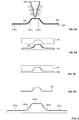
- the figures 6A and 6B illustrate the behavior of two successive folds 5, 6 at 0 ° during the forming operation. For the sake of clarity, only a pair of 0 ° folds are shown on these figures 6A and 6B , for example at the level of the first and second segments 54a, 54b of the fourth strip of the first ply and of the second band 62 of the second ply 6.
- the second ply covers the first ply by its end portions over a length L 1 .
- the male forming tool presses on the second ply to press it against the female forming tool, the fibers of the second ply slide in their longitudinal direction relative to the fibers of the first ply.
- the second ply remains overlapping the first ply over a length L ′ 1 , less than the initial length L 1 .
- the initial lap length is defined so that the lap length after forming is greater than a threshold value, for example 25 or 30mm.
- the first plies are draped outside the central area defined by the junction line 92, then the second plies are draped in said area and partially cover the first plies.
- the set of plies may include pairs of plies of the same orientation in which the aforementioned second plies are draped before the first plies, so that the first plies partially cover the second plies.
- the preform is made from 3.175 mm (1/8 inch) or 1.27 cm (1/2 inch) fibers, or by strip placement, i.e. by draping a strip formed from 'a single wide fiber, for example 15.24 cm (6 inches) or 30.48 (12 inches) wide.
- the fibers applied are fibers pre-impregnated with a thermoplastic or thermosetting resin.
- the set of plies is subjected to a forming operation, as described above, then to a hardening operation, also called a consolidation operation, these two operations possibly being combined and being carried out with the same tools. .
- the figures 7A, 7B and 7C illustrate the forming operation according to an alternative embodiment, in which the first plies 5, 105, 205 are locked in position during forming.
- the male forming tool comprises two parts, a central part 143 comprising the boss 143a and a frame 144 surrounding the central part.
- the frame is first lowered, as illustrated in figure 7B , to clamp the set of folds on its periphery between the frame and the female forming tool, and thus block the first folds 5, 105, 205.
- the central part 143 is lowered to perform the forming. This blocking of the first plies ensures that only the second plies move during forming, without causing the first plies.
- the part to be produced comprises a single central boss 12.
- preforms with more complex shapes having several bosses and / or recesses and / or ramps can be made by providing each sensitive area, capable of generating deformations of fibers in the forming process. one. or more orientations, systems of pairs of folds of the same orientation as described above, with bands or segments of bands of first and second plies overlapping at their end portions.
- the pairs of folds of the same orientation are not produced successively, but by inserting one or more folds of different orientations, in particular by inserting one or more folds of pairs of folds of different orientations. For example, firstly all the first plies 5, 105, 205 are draped, and then all the second plies 6, 106, 206 are draped.
- FIGS 8A to 8D illustrate a second embodiment of the method according to the invention, for producing a dry preform 101 in the form of a substantially rectilinear profile with an omega section, as illustrated on figure 8D , for example from dry carbon fibers provided with a binder.
- a ply assembly E2 is produced by superimposing several plies of fibers in orientations at 0 °, 90 °, + 45 ° and -45 °, on the application surface 221 of a draping tool 202, which here constitutes a male forming tools.
- the application surface 221 corresponds to the interior surface of the preform to be produced, and is provided with a longitudinal boss, the section of which corresponds to the section of the reinforcement to be produced.
- the surface thus has an upper flat part 221a connected to lateral flat parts 221b by two parts forming ramps 221c.
- the bands of fibers are applied here without contact, by means of an application head 103, as described in the aforementioned patent application, entitled “Process and machine for the production of preforms by application of fibers without compacting of oriented fibers. ".
- the re-routing means continuously drive the fibers to deposit them on the surface of the draping tool.
- the set E2 of folds E is subjected to a forming operation to be compacted between the male forming tool and a female forming tool 241, having a longitudinal groove of shape corresponding to that of the boss. , by relative bringing together of the two tools, as illustrated in figures 8B and 8C .
- This compaction is possibly carried out hot, by heating of the two tools.
- compaction is accomplished using a vacuum bag system in place of the female forming tool.
- the resulting preform 101 is then subjected to an operation of adding resin by injection and / or infusion to finally obtain a part made of composite material.
- pairs of successive 90 ° folds are made as shown in figure 9 .
- the head is moved along parallel paths to deposit three first segments 351a, 351b, 351c of tape, the first segments being spaced from each other by uncovered areas including the concave junction area connecting the flat parts. side 321c to the ramps 321b.
- the head is moved along parallel paths to deposit two second segments 361a, 361b on the uncovered areas, while partially covering the first segments.
- This type of application for the 90 ° orientations allows the fibers to slide during the forming operation, so that the fibers come perfectly against the junction zones connecting the ramps to the lateral flat parts.
- the same principle of pairs of folds with the same orientation can optionally be applied for the + 45 ° and -45 ° orientations.
- the principle of pairs of folds of the same orientation according to the invention will also be applied for the orientations at 0 °.
- the first ply is obtained by applying short fibers, of a few centimeters, for example of the order of 5 to 8 cm, one behind the other, by performing fiber cutting operations during each trajectory, as described in the aforementioned patent application.
- each fiber is cut into segments via its associated cutting means, while being continuously driven by its rerouting means.
- the second fold is made in the same way, so that the segments of the first fold and those of the second fold overlap.
Landscapes
- Engineering & Computer Science (AREA)
- Mechanical Engineering (AREA)
- Textile Engineering (AREA)
- Chemical & Material Sciences (AREA)
- Composite Materials (AREA)
- Moulding By Coating Moulds (AREA)
- Reinforced Plastic Materials (AREA)
Claims (9)
- Verfahren zur Herstellung von dreidimensionalen Vorformlingen (1, 101), umfassend- das Auftragen von kontinuierlichen Fasern (F) auf eine Auftragfläche (21, 221), um mehrere Lagen (5, 6, 105, 106, 205, 206) übereinanderliegender Fasern zu bilden, und- das Formen der Lagenanordnung, um einen Vorformling zu erhalten,wobei bei diesem Verfahren das Auftragen von Fasern mittels eines Faserauftragkopfes (3, 103) durchgeführt wird, um mehrere Lagen (5, 6, 105, 106, 205, 206) übereinanderliegender Fasern in verschiedenen Ausrichtungen durch relative Verlagerung des Auftragkopfs in Bezug auf die Auflagefläche gemäß verschiedenen Bahnen zu bilden, wobei jede Lage durch Auftragen von einem oder mehreren Bändern (51-57; 61-63) gemäß einer Ausrichtung mittels des Kopfes hergestellt wird, wobei jedes Band aus einer oder mehreren Fasern gebildet ist,
wobei das Auftragen von Fasern die Herstellung von mindestens zwei Lagen (5, 6; 105, 106; 205, 206) in derselben Ausrichtung umfasst,
wobei das Verfahren dadurch gekennzeichnet ist, dass sich für die Herstellung von zwei Lagen in derselben Ausrichtung die Fasern der zweiten Lage (6, 106, 206) mit Fasern (5, 105, 205) der ersten Lage mit ihren Endabschnitten teilweise derart überlagern, dass beim Formen eine relative Längsverlagerung der Fasern der zweiten Lage in Bezug auf die Fasern der ersten Lage erhalten wird, um die abschließende Form des Vorformlings herzustellen, wobei sich die Fasern der zwei Lagen über eine erste Länge (L1) derart überlagern, dass nach dem Formen die Fasern am Ende über eine zweite Länge (L'1) überlagert bleiben, die kürzer als die erste Länge ist. - Verfahren nach Anspruch 1, dadurch gekennzeichnet, dass die zwei Lagen (5, 6; 105, 106; 205, 206) derselben Ausrichtung nacheinander hergestellt werden.
- Verfahren nach Anspruch 1 oder 2, dadurch gekennzeichnet, dass es vor dem Formen das Arretieren der Lagenanordnung umfasst, um die ersten oder zweiten Lagen jedes Lagenpaars derselben Ausrichtung derart in Position zu arretieren, dass sich beim Formen nur die nicht arretierten zweiten oder ersten Lagen jedes Lagenpaars längs verlagern.
- Verfahren nach einem der Ansprüche 1 bis 3, dadurch gekennzeichnet, dass es das Auftragen von mehreren Faserlagen auf eine etwa ebene Auftragfläche, die Verlagerung der Lagenanordnung zu einer Presse und das Formen der Lagenanordnung zwischen dem männlichen Formungswerkzeug und dem weiblichen Formungswerkzeug der Presse umfasst.
- Verfahren nach einem der Ansprüche 1 bis 4, dadurch gekennzeichnet, dass es umfasst- das Auftragen von trockenen Fasern, die mit einem Bindemittel ausgestattet sind, und/oder- das Auftragen von mit einem oder mehreren Harzen vorimprägnierten Fasern, und/oder- das Auftragen von trockenen Fasern und das Auftragen eines Bindemittels und/oder von Harz auf die Auftragfläche und/oder die bereits aufgetragenen Fasern.
- Verfahren nach Anspruch 5, dadurch gekennzeichnet, dass das Bindemittel und/oder das Imprägnierharz beim Auftragen der Fasern die Haftung der aufgetragenen Fasern auf der Auftragfläche und/oder den zuvor aufgetragenen Fasern erlaubt und somit den Zusammenhalt des Vorformlings sichert.
- Verfahren nach Anspruch 6, dadurch gekennzeichnet, dass das Bindemittel und/oder das Imprägnierharz beim Auftragen der Fasern erwärmt werden, um die Haftung zu erlauben.
- Verfahren nach einem der Ansprüche 1 bis 7, dadurch gekennzeichnet, dass es umfasst- einen Definitionsschritt der Zonen, in denen die Fasern bestimmter Ausrichtung beim Formen hohen Kräften ausgesetzt werden, und- einen Definitionsschritt von Bahnen für die Herstellung der Lagen, umfassend Lagen derselben Ausrichtung, die sich in den Zonen teilweise überlagern.
- Verfahren zur Herstellung von Teilen aus Verbundmaterial, dadurch gekennzeichnet, dass es umfasst- die Herstellung eines Vorformlings nach einem der Ansprüche 1 bis 8,- einen Imprägnierschritt des Vorformlings mit Harz, wobei der Imprägnierschritt das Hinzufügen von einem oder mehreren Harzen durch Infusion oder Injektion oder das Erwärmen des Vorformlings zum Imprägnieren des gesamten Vorformlings mit dem oder den Harzen umfasst, und- einen Schritt des Härtens.
Applications Claiming Priority (2)
| Application Number | Priority Date | Filing Date | Title |
|---|---|---|---|
| FR1401062A FR3020779B1 (fr) | 2014-05-09 | 2014-05-09 | Procede de realisation de preformes par application et formage de fibres orientees |
| PCT/FR2015/000091 WO2015170017A1 (fr) | 2014-05-09 | 2015-04-28 | Procede de realisation de preformes par application et formage de fibres orientees |
Publications (2)
| Publication Number | Publication Date |
|---|---|
| EP3140104A1 EP3140104A1 (de) | 2017-03-15 |
| EP3140104B1 true EP3140104B1 (de) | 2021-06-16 |
Family
ID=50976747
Family Applications (1)
| Application Number | Title | Priority Date | Filing Date |
|---|---|---|---|
| EP15721762.1A Active EP3140104B1 (de) | 2014-05-09 | 2015-04-28 | Verfahren zur erzeugung von vorformlingen durch aufbringen und formen ausgerichteter fasern |
Country Status (3)
| Country | Link |
|---|---|
| EP (1) | EP3140104B1 (de) |
| FR (1) | FR3020779B1 (de) |
| WO (1) | WO2015170017A1 (de) |
Families Citing this family (5)
| Publication number | Priority date | Publication date | Assignee | Title |
|---|---|---|---|---|
| FR3047197B1 (fr) * | 2016-02-02 | 2018-01-12 | Coriolis Group | Procede de realisation de preformes tridimensionnelles par formage de preformes initiales mises sous tension |
| FR3047196B1 (fr) * | 2016-02-02 | 2018-09-28 | Coriolis Group | Procede de realisation de preformes tridimensionnelles par formage de preformes initiales avec des voiles |
| CN110978561A (zh) * | 2019-12-30 | 2020-04-10 | 中国航空制造技术研究院 | 一种全铺层结构复合材料罩体的纤维预制体制备方法 |
| FR3120007B1 (fr) | 2021-02-24 | 2023-11-03 | Composites Busch Sa | Procédé de fabrication d’un matériau composite |
| US12617162B2 (en) * | 2022-11-14 | 2026-05-05 | Rohr, Inc. | Forming thermoplastic structure stamping blank using automated fiber placement device |
Citations (1)
| Publication number | Priority date | Publication date | Assignee | Title |
|---|---|---|---|---|
| WO2012045969A1 (fr) * | 2010-10-06 | 2012-04-12 | Coriolis Composites | Procede de fabrication de raidisseurs en materiau composite |
Family Cites Families (3)
| Publication number | Priority date | Publication date | Assignee | Title |
|---|---|---|---|---|
| US6527533B2 (en) | 2000-12-29 | 2003-03-04 | Ford Global Technologies, Inc. | Processing systems for automated manufacture of preforms |
| FR2952577B1 (fr) * | 2009-11-19 | 2011-11-04 | Airbus Operations Sas | Procede de fabrication d'une piece courbe en materiau composite et dispositif pour la fabrication d'une piece courbe en materiau composite |
| WO2012152296A1 (de) * | 2011-05-06 | 2012-11-15 | Irene Brockmanns | Verfahren zur herstellung eines textilen halbzeuges sowie textiles halbzeug für eine textile faserverbundstruktur |
-
2014
- 2014-05-09 FR FR1401062A patent/FR3020779B1/fr not_active Expired - Fee Related
-
2015
- 2015-04-28 EP EP15721762.1A patent/EP3140104B1/de active Active
- 2015-04-28 WO PCT/FR2015/000091 patent/WO2015170017A1/fr not_active Ceased
Patent Citations (1)
| Publication number | Priority date | Publication date | Assignee | Title |
|---|---|---|---|---|
| WO2012045969A1 (fr) * | 2010-10-06 | 2012-04-12 | Coriolis Composites | Procede de fabrication de raidisseurs en materiau composite |
Also Published As
| Publication number | Publication date |
|---|---|
| EP3140104A1 (de) | 2017-03-15 |
| FR3020779A1 (fr) | 2015-11-13 |
| FR3020779B1 (fr) | 2016-06-03 |
| WO2015170017A1 (fr) | 2015-11-12 |
Similar Documents
| Publication | Publication Date | Title |
|---|---|---|
| EP2259913B1 (de) | Verfahren und vorrichtung zum formen eines gebogenen bauteils aus verbundmaterial | |
| EP3519166B1 (de) | Verfahren zur herstellung von verbundstoffmaterialteilen durch imprägnierung einer spezifischen vorform | |
| CA2862686C (fr) | Procede de formage par estampage d'un materiau composite thermoplastique a renfort fibreux continu | |
| EP3140104A1 (de) | Verfahren zur erzeugung von vorformlingen durch aufbringen und formen ausgerichteter fasern | |
| EP3277486A1 (de) | Faserauftragskopf mit spezieller auftragsrolle | |
| EP3177454A1 (de) | Verfahren zur herstellung eines verstärkten teils mit verbundstoff | |
| EP3411207B1 (de) | Verfahren zur herstellung dreidimensionaler vorformen aus ausgangsvormen mit decklagen | |
| FR3070623A1 (fr) | Procede de realisation d’une piece en materiau composite par aiguilletage oriente d’une preforme | |
| WO2015170016A1 (fr) | Procédé et machine pour la réalisation de préformes par application sans compactage de fibres orientées | |
| EP3606735A1 (de) | Verfahren zur herstellung von verbundstoffteilen aus genadelten vorformen | |
| EP3774305B1 (de) | Verfahren zur herstellung eines teils aus einem verbundwerkstoff durch vernadeln von untermengen von lagen | |
| EP2625027B1 (de) | Verfahren zur herstellung von versteifungen aus einem verbundwerkstoff | |
| FR3120007A1 (fr) | Procédé de fabrication d’un matériau composite | |
| EP3204219B1 (de) | Verfahren zur herstellung von thermoplastischen kunststoffteilen, die mit kontinuierlichen thermoplastischen fasern verstärkt sind | |
| EP2846987A1 (de) | Verfahren zur herstellung einer verbundhaut zur herstellung einer nicht abstreifbaren drehenden symmetrischen manschette | |
| WO2017051081A1 (fr) | Procédé de réalisation de pièces métalliques renforcées de fibres thermoplastiques continues | |
| WO2023152430A1 (fr) | Procédé de réalisation d'une pièce en matériau thermoplastique | |
| EP3411220B1 (de) | Verfahren zur herstellung von dreidimensionalen vorformen mittels formen von gespannten vorformen | |
| FR3037524A1 (fr) | Tete d'application de fibres avec systeme de guidage particulier | |
| EP3365162B1 (de) | Verfahren zur flachen herstellung einer komplexen verbundstoffvorform |
Legal Events
| Date | Code | Title | Description |
|---|---|---|---|
| STAA | Information on the status of an ep patent application or granted ep patent |
Free format text: STATUS: THE INTERNATIONAL PUBLICATION HAS BEEN MADE |
|
| PUAI | Public reference made under article 153(3) epc to a published international application that has entered the european phase |
Free format text: ORIGINAL CODE: 0009012 |
|
| STAA | Information on the status of an ep patent application or granted ep patent |
Free format text: STATUS: REQUEST FOR EXAMINATION WAS MADE |
|
| 17P | Request for examination filed |
Effective date: 20161115 |
|
| AK | Designated contracting states |
Kind code of ref document: A1 Designated state(s): AL AT BE BG CH CY CZ DE DK EE ES FI FR GB GR HR HU IE IS IT LI LT LU LV MC MK MT NL NO PL PT RO RS SE SI SK SM TR |
|
| AX | Request for extension of the european patent |
Extension state: BA ME |
|
| DAV | Request for validation of the european patent (deleted) | ||
| DAX | Request for extension of the european patent (deleted) | ||
| RAP1 | Party data changed (applicant data changed or rights of an application transferred) |
Owner name: CORIOLIS GROUP |
|
| STAA | Information on the status of an ep patent application or granted ep patent |
Free format text: STATUS: EXAMINATION IS IN PROGRESS |
|
| 17Q | First examination report despatched |
Effective date: 20190627 |
|
| GRAP | Despatch of communication of intention to grant a patent |
Free format text: ORIGINAL CODE: EPIDOSNIGR1 |
|
| STAA | Information on the status of an ep patent application or granted ep patent |
Free format text: STATUS: GRANT OF PATENT IS INTENDED |
|
| INTG | Intention to grant announced |
Effective date: 20200917 |
|
| GRAJ | Information related to disapproval of communication of intention to grant by the applicant or resumption of examination proceedings by the epo deleted |
Free format text: ORIGINAL CODE: EPIDOSDIGR1 |
|
| STAA | Information on the status of an ep patent application or granted ep patent |
Free format text: STATUS: EXAMINATION IS IN PROGRESS |
|
| GRAP | Despatch of communication of intention to grant a patent |
Free format text: ORIGINAL CODE: EPIDOSNIGR1 |
|
| STAA | Information on the status of an ep patent application or granted ep patent |
Free format text: STATUS: GRANT OF PATENT IS INTENDED |
|
| INTC | Intention to grant announced (deleted) | ||
| INTG | Intention to grant announced |
Effective date: 20210202 |
|
| GRAS | Grant fee paid |
Free format text: ORIGINAL CODE: EPIDOSNIGR3 |
|
| GRAA | (expected) grant |
Free format text: ORIGINAL CODE: 0009210 |
|
| STAA | Information on the status of an ep patent application or granted ep patent |
Free format text: STATUS: THE PATENT HAS BEEN GRANTED |
|
| AK | Designated contracting states |
Kind code of ref document: B1 Designated state(s): AL AT BE BG CH CY CZ DE DK EE ES FI FR GB GR HR HU IE IS IT LI LT LU LV MC MK MT NL NO PL PT RO RS SE SI SK SM TR |
|
| REG | Reference to a national code |
Ref country code: GB Ref legal event code: FG4D Free format text: NOT ENGLISH |
|
| REG | Reference to a national code |
Ref country code: CH Ref legal event code: EP |
|
| REG | Reference to a national code |
Ref country code: DE Ref legal event code: R096 Ref document number: 602015070415 Country of ref document: DE |
|
| REG | Reference to a national code |
Ref country code: AT Ref legal event code: REF Ref document number: 1401970 Country of ref document: AT Kind code of ref document: T Effective date: 20210715 |
|
| REG | Reference to a national code |
Ref country code: IE Ref legal event code: FG4D Free format text: LANGUAGE OF EP DOCUMENT: FRENCH |
|
| REG | Reference to a national code |
Ref country code: LT Ref legal event code: MG9D |
|
| PG25 | Lapsed in a contracting state [announced via postgrant information from national office to epo] |
Ref country code: FI Free format text: LAPSE BECAUSE OF FAILURE TO SUBMIT A TRANSLATION OF THE DESCRIPTION OR TO PAY THE FEE WITHIN THE PRESCRIBED TIME-LIMIT Effective date: 20210616 Ref country code: LT Free format text: LAPSE BECAUSE OF FAILURE TO SUBMIT A TRANSLATION OF THE DESCRIPTION OR TO PAY THE FEE WITHIN THE PRESCRIBED TIME-LIMIT Effective date: 20210616 Ref country code: BG Free format text: LAPSE BECAUSE OF FAILURE TO SUBMIT A TRANSLATION OF THE DESCRIPTION OR TO PAY THE FEE WITHIN THE PRESCRIBED TIME-LIMIT Effective date: 20210916 Ref country code: HR Free format text: LAPSE BECAUSE OF FAILURE TO SUBMIT A TRANSLATION OF THE DESCRIPTION OR TO PAY THE FEE WITHIN THE PRESCRIBED TIME-LIMIT Effective date: 20210616 |
|
| REG | Reference to a national code |
Ref country code: AT Ref legal event code: MK05 Ref document number: 1401970 Country of ref document: AT Kind code of ref document: T Effective date: 20210616 |
|
| REG | Reference to a national code |
Ref country code: NL Ref legal event code: MP Effective date: 20210616 |
|
| PG25 | Lapsed in a contracting state [announced via postgrant information from national office to epo] |
Ref country code: NO Free format text: LAPSE BECAUSE OF FAILURE TO SUBMIT A TRANSLATION OF THE DESCRIPTION OR TO PAY THE FEE WITHIN THE PRESCRIBED TIME-LIMIT Effective date: 20210916 Ref country code: RS Free format text: LAPSE BECAUSE OF FAILURE TO SUBMIT A TRANSLATION OF THE DESCRIPTION OR TO PAY THE FEE WITHIN THE PRESCRIBED TIME-LIMIT Effective date: 20210616 Ref country code: SE Free format text: LAPSE BECAUSE OF FAILURE TO SUBMIT A TRANSLATION OF THE DESCRIPTION OR TO PAY THE FEE WITHIN THE PRESCRIBED TIME-LIMIT Effective date: 20210616 Ref country code: GR Free format text: LAPSE BECAUSE OF FAILURE TO SUBMIT A TRANSLATION OF THE DESCRIPTION OR TO PAY THE FEE WITHIN THE PRESCRIBED TIME-LIMIT Effective date: 20210917 Ref country code: LV Free format text: LAPSE BECAUSE OF FAILURE TO SUBMIT A TRANSLATION OF THE DESCRIPTION OR TO PAY THE FEE WITHIN THE PRESCRIBED TIME-LIMIT Effective date: 20210616 |
|
| PG25 | Lapsed in a contracting state [announced via postgrant information from national office to epo] |
Ref country code: CZ Free format text: LAPSE BECAUSE OF FAILURE TO SUBMIT A TRANSLATION OF THE DESCRIPTION OR TO PAY THE FEE WITHIN THE PRESCRIBED TIME-LIMIT Effective date: 20210616 Ref country code: EE Free format text: LAPSE BECAUSE OF FAILURE TO SUBMIT A TRANSLATION OF THE DESCRIPTION OR TO PAY THE FEE WITHIN THE PRESCRIBED TIME-LIMIT Effective date: 20210616 Ref country code: SM Free format text: LAPSE BECAUSE OF FAILURE TO SUBMIT A TRANSLATION OF THE DESCRIPTION OR TO PAY THE FEE WITHIN THE PRESCRIBED TIME-LIMIT Effective date: 20210616 Ref country code: SK Free format text: LAPSE BECAUSE OF FAILURE TO SUBMIT A TRANSLATION OF THE DESCRIPTION OR TO PAY THE FEE WITHIN THE PRESCRIBED TIME-LIMIT Effective date: 20210616 Ref country code: RO Free format text: LAPSE BECAUSE OF FAILURE TO SUBMIT A TRANSLATION OF THE DESCRIPTION OR TO PAY THE FEE WITHIN THE PRESCRIBED TIME-LIMIT Effective date: 20210616 Ref country code: PT Free format text: LAPSE BECAUSE OF FAILURE TO SUBMIT A TRANSLATION OF THE DESCRIPTION OR TO PAY THE FEE WITHIN THE PRESCRIBED TIME-LIMIT Effective date: 20211018 Ref country code: NL Free format text: LAPSE BECAUSE OF FAILURE TO SUBMIT A TRANSLATION OF THE DESCRIPTION OR TO PAY THE FEE WITHIN THE PRESCRIBED TIME-LIMIT Effective date: 20210616 Ref country code: ES Free format text: LAPSE BECAUSE OF FAILURE TO SUBMIT A TRANSLATION OF THE DESCRIPTION OR TO PAY THE FEE WITHIN THE PRESCRIBED TIME-LIMIT Effective date: 20210616 Ref country code: AT Free format text: LAPSE BECAUSE OF FAILURE TO SUBMIT A TRANSLATION OF THE DESCRIPTION OR TO PAY THE FEE WITHIN THE PRESCRIBED TIME-LIMIT Effective date: 20210616 |
|
| PG25 | Lapsed in a contracting state [announced via postgrant information from national office to epo] |
Ref country code: PL Free format text: LAPSE BECAUSE OF FAILURE TO SUBMIT A TRANSLATION OF THE DESCRIPTION OR TO PAY THE FEE WITHIN THE PRESCRIBED TIME-LIMIT Effective date: 20210616 |
|
| REG | Reference to a national code |
Ref country code: DE Ref legal event code: R097 Ref document number: 602015070415 Country of ref document: DE |
|
| PLBE | No opposition filed within time limit |
Free format text: ORIGINAL CODE: 0009261 |
|
| STAA | Information on the status of an ep patent application or granted ep patent |
Free format text: STATUS: NO OPPOSITION FILED WITHIN TIME LIMIT |
|
| PG25 | Lapsed in a contracting state [announced via postgrant information from national office to epo] |
Ref country code: DK Free format text: LAPSE BECAUSE OF FAILURE TO SUBMIT A TRANSLATION OF THE DESCRIPTION OR TO PAY THE FEE WITHIN THE PRESCRIBED TIME-LIMIT Effective date: 20210616 |
|
| 26N | No opposition filed |
Effective date: 20220317 |
|
| PG25 | Lapsed in a contracting state [announced via postgrant information from national office to epo] |
Ref country code: AL Free format text: LAPSE BECAUSE OF FAILURE TO SUBMIT A TRANSLATION OF THE DESCRIPTION OR TO PAY THE FEE WITHIN THE PRESCRIBED TIME-LIMIT Effective date: 20210616 |
|
| PG25 | Lapsed in a contracting state [announced via postgrant information from national office to epo] |
Ref country code: IT Free format text: LAPSE BECAUSE OF FAILURE TO SUBMIT A TRANSLATION OF THE DESCRIPTION OR TO PAY THE FEE WITHIN THE PRESCRIBED TIME-LIMIT Effective date: 20210616 |
|
| REG | Reference to a national code |
Ref country code: CH Ref legal event code: PL |
|
| REG | Reference to a national code |
Ref country code: BE Ref legal event code: MM Effective date: 20220430 |
|
| PG25 | Lapsed in a contracting state [announced via postgrant information from national office to epo] |
Ref country code: MC Free format text: LAPSE BECAUSE OF FAILURE TO SUBMIT A TRANSLATION OF THE DESCRIPTION OR TO PAY THE FEE WITHIN THE PRESCRIBED TIME-LIMIT Effective date: 20210616 Ref country code: LU Free format text: LAPSE BECAUSE OF NON-PAYMENT OF DUE FEES Effective date: 20220428 Ref country code: LI Free format text: LAPSE BECAUSE OF NON-PAYMENT OF DUE FEES Effective date: 20220430 Ref country code: CH Free format text: LAPSE BECAUSE OF NON-PAYMENT OF DUE FEES Effective date: 20220430 |
|
| PG25 | Lapsed in a contracting state [announced via postgrant information from national office to epo] |
Ref country code: BE Free format text: LAPSE BECAUSE OF NON-PAYMENT OF DUE FEES Effective date: 20220430 |
|
| PG25 | Lapsed in a contracting state [announced via postgrant information from national office to epo] |
Ref country code: IE Free format text: LAPSE BECAUSE OF NON-PAYMENT OF DUE FEES Effective date: 20220428 |
|
| PG25 | Lapsed in a contracting state [announced via postgrant information from national office to epo] |
Ref country code: HU Free format text: LAPSE BECAUSE OF FAILURE TO SUBMIT A TRANSLATION OF THE DESCRIPTION OR TO PAY THE FEE WITHIN THE PRESCRIBED TIME-LIMIT; INVALID AB INITIO Effective date: 20150428 |
|
| PG25 | Lapsed in a contracting state [announced via postgrant information from national office to epo] |
Ref country code: MK Free format text: LAPSE BECAUSE OF FAILURE TO SUBMIT A TRANSLATION OF THE DESCRIPTION OR TO PAY THE FEE WITHIN THE PRESCRIBED TIME-LIMIT Effective date: 20210616 Ref country code: CY Free format text: LAPSE BECAUSE OF FAILURE TO SUBMIT A TRANSLATION OF THE DESCRIPTION OR TO PAY THE FEE WITHIN THE PRESCRIBED TIME-LIMIT Effective date: 20210616 |
|
| PG25 | Lapsed in a contracting state [announced via postgrant information from national office to epo] |
Ref country code: TR Free format text: LAPSE BECAUSE OF FAILURE TO SUBMIT A TRANSLATION OF THE DESCRIPTION OR TO PAY THE FEE WITHIN THE PRESCRIBED TIME-LIMIT Effective date: 20210616 |
|
| PG25 | Lapsed in a contracting state [announced via postgrant information from national office to epo] |
Ref country code: MT Free format text: LAPSE BECAUSE OF FAILURE TO SUBMIT A TRANSLATION OF THE DESCRIPTION OR TO PAY THE FEE WITHIN THE PRESCRIBED TIME-LIMIT Effective date: 20210616 |
|
| PGFP | Annual fee paid to national office [announced via postgrant information from national office to epo] |
Ref country code: DE Payment date: 20250319 Year of fee payment: 11 |
|
| PGFP | Annual fee paid to national office [announced via postgrant information from national office to epo] |
Ref country code: GB Payment date: 20260320 Year of fee payment: 12 |
|
| PGFP | Annual fee paid to national office [announced via postgrant information from national office to epo] |
Ref country code: FR Payment date: 20260320 Year of fee payment: 12 |