EP3140132B1 - Pneumatiques de véhicules - Google Patents
Pneumatiques de véhicules Download PDFInfo
- Publication number
- EP3140132B1 EP3140132B1 EP15704308.4A EP15704308A EP3140132B1 EP 3140132 B1 EP3140132 B1 EP 3140132B1 EP 15704308 A EP15704308 A EP 15704308A EP 3140132 B1 EP3140132 B1 EP 3140132B1
- Authority
- EP
- European Patent Office
- Prior art keywords
- belt
- belt ply
- reinforcing elements
- ply
- circumferential direction
- Prior art date
- Legal status (The legal status is an assumption and is not a legal conclusion. Google has not performed a legal analysis and makes no representation as to the accuracy of the status listed.)
- Active
Links
Images






Classifications
-
- B—PERFORMING OPERATIONS; TRANSPORTING
- B60—VEHICLES IN GENERAL
- B60C—VEHICLE TYRES; TYRE INFLATION; TYRE CHANGING; CONNECTING VALVES TO INFLATABLE ELASTIC BODIES IN GENERAL; DEVICES OR ARRANGEMENTS RELATED TO TYRES
- B60C9/00—Reinforcements or ply arrangement of pneumatic tyres
- B60C9/18—Structure or arrangement of belts or breakers, crown-reinforcing or cushioning layers
- B60C9/20—Structure or arrangement of belts or breakers, crown-reinforcing or cushioning layers built-up from rubberised plies each having all cords arranged substantially parallel
- B60C9/2003—Structure or arrangement of belts or breakers, crown-reinforcing or cushioning layers built-up from rubberised plies each having all cords arranged substantially parallel characterised by the materials of the belt cords
- B60C9/2006—Structure or arrangement of belts or breakers, crown-reinforcing or cushioning layers built-up from rubberised plies each having all cords arranged substantially parallel characterised by the materials of the belt cords consisting of steel cord plies only
Definitions
- the invention relates to a vehicle pneumatic tire for commercial vehicles with a carcass, constructed with a radially outside of the carcass belt and with a radially outside of the belt on the belt built profiled tread, the belt of at least four from radially inside to radially outside lying on each other arranged belt layers is formed, wherein in the radial direction R most inwardly disposed, first belt layer is formed with parallel in rubber embedded reinforcements and the radially outermost R outermost, fourth belt layer with parallel embedded in rubber reinforcements, wherein in the radial direction between the first belt ply and the fourth belt ply, at least one second belt ply with parallel rubber-embedded reinforcements disposed on the first belt ply, and a third belt ply with parallel rubber-embedded reinforcements n, which is arranged on the second belt layer is formed.
- Conventional commercial vehicle pneumatic tires usually have a four-belt with so-called triangular configuration, in which two working positions are arranged in the radial direction, the steel cords each have an angle of about 15 ° to 30 ° to the circumferential direction, wherein the steel cords one working position and the second working position are inclined in different axial direction A.
- the working positions thereby form a cross dressing.
- Below the working positions is in such belts usually formed as a barrier layer belt layer whose steel cords have an angle of 45 ° to 60 ° to the circumferential direction, whereby the cords of the working positions and the blocking position form a triangle.
- the fourth belt layer formed additional protective layer whose steel cords also have an angle of about 15 ° to 30 ° to the circumferential direction of the vehicle tire.
- Such belts have a limited circumferential rigidity.
- the resulting mobility of the belt edges can adversely affect the durability of the tire.
- the belt may also be subject to radial expansion during operation. This growth can lead to excessive uneven wear on the tire.
- the circumferential stiffness of the belt is increased, which has a positive effect on the durability of the belt.
- the influence of the 0 ° position is essentially limited to the radially outer working position.
- the inner working position is formed with a remaining mobility, with further negative influences on durability and abrasion.
- the invention has for its object to provide such a pneumatic vehicle tire for commercial vehicles with at least four belt layers, in which in a simple manner, taking advantage of the formation of a four-belt with two working positions, a zero degree position and a locked position further improvement in durability is possible.
- a pneumatic vehicle tire for commercial vehicles with a carcass, constructed with a radially outside of the carcass belt and with a radially outside the belt on the belt built profiled tread, the belt of at least four from radially inward to radially outward formed lying belt layers, wherein the four of the belt layers in the radial direction R arranged farthest inside, first belt layer formed with parallel in rubber embedded reinforcements and in the radial direction R outermost, fourth belt layer with parallel embedded in rubber reinforcements is, wherein in the radial direction between the first belt ply and the fourth belt ply at least a second belt ply with parallel rubber-embedded reinforcements, which is arranged on the first belt ply, and a third belt belt age with parallel rubber-embedded strength members disposed on the second belt ply, according to the features of claim 1, wherein the first belt ply and the fourth belt ply are work plys in which the first belt layer strength members are aligned in
- the training allows the maintenance of the advantageous in terms of good power transmission in the circumferential and transverse directions and low abrasion training with two working positions, a 0 ° position and a locking position.
- the intermediate positioning of the two layers between the first belt layer formed as a working position and the fourth belt layer configured as a working position increases the distance between the two working positions relative to one another without additional measures.
- the formation and effect of shear forces between the belt layer ends of the working positions can thus already be reduced, which has a positive effect on the durability.
- the zero grade position positioned between the working positions hinders the creation of unwanted lateral deformation of the belt edges.
- the additionally positioned belt position with angle ⁇ of its reinforcing elements to the circumferential direction U with 40 ° ⁇ 75 ° additionally blocks or blocks further deformation.
- highly effective lateral deformation can be prevented and durability can be increased.
- the durability of the carcass can be increased by avoiding compression.
- the second belt ply is that belt ply whose reinforcing elements include in their orientation an angle ⁇ to the circumferential direction U with 40 ° ⁇ 75 °
- the third belt ply that one belt ply is, whose Reinforcement in their orientation an angle ⁇ to the circumferential direction U with 0 ° ⁇ 5 ° include.
- a pneumatic vehicle tire according to the features of claim 3, wherein radially outside of the third belt layer between the third belt layer and fourth belt layer, another belt layer is formed whose strength member in their orientation an angle ( ⁇ ) to the circumferential direction U with 40 ° ⁇ ⁇ ⁇ 75 °, wherein viewed in the circumferential direction U of the vehicle tire, the strength members of the second belt ply have an opposite axial inclination direction to the Reinforcements the further belt layer have.
- the "ply-steer" effect can be reduced in a simple manner while minimizing the shear forces acting between the working positions.
- the third belt ply is that belt ply whose reinforcing elements include in their orientation an angle ⁇ to the circumferential direction U with 40 ° ⁇ 75 °, and that the second belt ply that one belt ply is whose strength element in their orientation an angle ⁇ to the circumferential direction U with 0 ° ⁇ 5 ° include.
- the durability of the belt and the tire can be further improved.
- Particularly advantageous for achieving an improved abrasion pattern is the formation of a pneumatic vehicle tire according to the features of claim 5, wherein viewed in the circumferential direction U, the strength members of the first belt ply and the strength members of the belt ply, which include in their orientation the angle ⁇ to the circumferential direction U, the same axial Have direction of inclination. This further favors the formation of a good footprint of the tire.
- Particularly advantageous for achieving an improved abrasion pattern is the formation of a pneumatic vehicle tire according to the features of claim 6, wherein the first belt layer is formed in its axial extent in the pneumatic vehicle tire larger than all other belt layers of the belt. As a result, the durability of the belt and the tire can be further improved.
- Particularly advantageous for achieving an improved abrasion pattern is the formation of a pneumatic vehicle tire according to the features of claim 7, wherein the belt layer, whose reinforcing elements are aligned in their orientation with an angle ⁇ to the circumferential direction U, formed smaller in its axial extent than all other belt layers of belt.
- the durability of the belt and the tire can be further improved and a uniform abrasion can be made possible.
- the reinforcements of the additional belt layer an opposite axial direction of inclination to the reinforcements of the belt layer, which include in their orientation the angle ⁇ to the circumferential direction U, in addition, the "ply-steer" effect can be further improved. Crack migration to the carcass can be limited and the durability of the tire improved.
- Particularly advantageous for achieving an improved abrasion pattern is the formation of a pneumatic vehicle tire according to the features of claim 9, wherein the first belt layer strength members and fourth belt layer strength members are steel cords. As a result, durability and rolling resistance can be promoted.
- Particularly advantageous for achieving an improved abrasion pattern is the formation of a pneumatic vehicle tire according to the features of claim 10, wherein the strength members of the two trained as working positions first and fourth belt layer in the tire are stretchable formed with an elongation D of D ⁇ 0.2% at 10% the breaking force. As a result, durability and rolling resistance can be promoted.
- Particularly advantageous for achieving an improved abrasion pattern is the formation of a pneumatic vehicle tire according to the features of claim 11.
- the durability of the tire can be further promoted.
- durability and rolling resistance can be promoted.
- Particularly advantageous for achieving an improved abrasion pattern is the formation of a pneumatic vehicle tire according to the features of claim 12, wherein the strength members of the belt layer, which include in their orientation the angle ⁇ to the circumferential direction U, are steel strength members.
- the strength members of the belt layer which include in their orientation the angle ⁇ to the circumferential direction U, are steel strength members.
- Particularly advantageous for achieving an improved abrasion pattern is the formation of a pneumatic vehicle tire according to the features of claim 13, wherein the strength members of the belt layer, which include in their orientation the angle ⁇ to the circumferential direction U, steel cords. As a result, durability and rolling resistance can be promoted.
- Particularly advantageous for achieving an improved abrasion pattern is the formation of a pneumatic vehicle tire according to the features of claim 14, wherein the Reinforcements of the other belt layer steel cords are. As a result, durability and rolling resistance can be promoted.
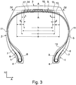
- Fig.1 and Fig.2 show a commercial vehicle pneumatic tire radial type with two extending in the radial direction R of the vehicle tire side walls 2 and an axially formed therebetween crown region 3. Also entered is the equatorial plane ⁇ - ⁇ .
- the side walls 2 are each formed with a bead region 1 at their extension end pointing inward in the radial direction R, in which a bead core 4 of known type which extends in the circumferential direction U over the circumference of the tire is formed in the circumferential direction.
- the bead cores 4 are formed in a known manner from in the circumferential direction U of the vehicle pneumatic tire, wound wrapped in rubber wire.
- a cross-sectionally triangular apex (apex) 6 is formed of hard rubber material.
- the pneumatic vehicle tire is formed with a carcass 5, which, starting from the bead core 4 formed in the left bead region 1 of the vehicle pneumatic tire in the radial direction R of the pneumatic vehicle tire, passes outwardly through the left side wall 2 to the crown region 3 and in the crown region 3 in the axial direction A of the pneumatic vehicle tire extends radially inward to the right side wall 2 and in the right side wall 2 of the pneumatic vehicle tire to the bead core 4 formed in the bead region 1 of the right side wall 2.
- the carcass 5 is in both bead portions 1 respectively along the axial inside of the bead core 4 to the radial inside of each bead core 4, then in extension in the axial direction A along the radial inside of the bead core 4 to the axial outside of the bead core 4 and then in extension formed on the axial outer side of the bead core 4 as an envelope part 7 extends radially outward.
- the carcass 5 extends with its envelope part 7 along the axial outside of the apex 6 and ends on the axial outside of the apex 7.
- the carcass 5 is in a known, not shown manner from a circumferentially U over the entire circumference of the vehicle pneumatic tire extended carcass ply with parallel cords embedded in rubber - for example Steel cords - which extend in the region of the side walls 2 substantially in the radial direction R and in the crown region substantially in the axial direction A, formed.
- an inner layer 12 of known, especially impermeable rubber material extends on the side of the carcass 5 facing the inner side of the tire.
- an additional bead reinforcement strip 8 which extends over the entire circumference of the vehicle pneumatic tire, is formed on the side of the carcass 5 facing away from the bead core 4.
- the bead reinforcement strip 8 is, for example, a strip of material embedded in rubber of parallel reinforcements of textile or metallic type.
- a belt 9 extending over the entire periphery of the vehicle pneumatic tire in the circumferential direction U and in the axial direction A from the left tire shoulder to the right tire shoulder is formed is formed of four in the radial direction R from inside to outside over each other and superimposed belt plies 13,17, 14 and 15 is formed.
- Radially outside the belt 9 is formed on the belt 9 over the entire circumference of the pneumatic vehicle tire in the circumferential direction U and extended in the axial direction A from the left tire shoulder to the right tire shoulder profiled tread 10 of known type, which completely covers the belt 9.
- a side wall rubber strip 11 is formed in a known manner on the side of the carcass 5 pointing away from the tire, which extends in the radial direction R from the bead area 1 to the profiled tread 10 in the crown area 3.
- the belt layer 13 of the belt 9 arranged furthest in the radial direction R forms the first belt ply 13.
- the belt ply 17 arranged on the first belt ply 13 in the radial direction R outside the first belt ply 13 forms the second belt ply.
- the belt layer 14 arranged in the radial direction R outside the second belt ply on the second belt ply forms the third belt ply.
- the belt layer 15 arranged in the radial direction R outside the third belt ply on the third belt ply forms the fourth belt layer 15.
- the belt layer 13 and the belt layer 15 are formed as working positions of the tire and each extend in the circumferential direction U over the entire circumference of the pneumatic vehicle tire and in the axial direction A from the left tire shoulder to the right tire shoulder.
- the working layer 13 is formed from a layer of thread-shaped parallel reinforcing members 23 embedded in rubber, which extend over the entire axial width A measured width a of the belt layer 13 is substantially rectilinear and include an inclination angle ⁇ to the circumferential direction U with 10 ° ⁇ ⁇ ⁇ 45 °.
- the working ply 15 is formed from a ply of thread-like parallel reinforcing members 25 embedded in rubber, which extend substantially rectilinearly over the entire axial width c of the belt ply 15 and enclose an inclination angle ⁇ to the circumferential direction U with 10 ° ⁇ 45 °.
- the inclination direction of the reinforcing elements 25 of the working layers 15 along the circumferential direction U is formed in the opposite axial direction A to the direction of inclination of the reinforcing elements 23 of the working layer 13.
- the belt layer 14 formed in the radial direction R between the first belt ply (lower work position) 13 and fourth belt ply (upper work position) 15 extends in the circumferential direction U over the entire circumference of the pneumatic vehicle tire and in the axial direction A from the left tire shoulder to the right tire shoulder and is in the zero degree Situation formed.
- the belt ply 14 is formed from parallel thread-like reinforcements embedded in rubber, which extend in a straight line over the entire circumference of the vehicle pneumatic tire, including an angle ⁇ with 0 ° ⁇ ⁇ ⁇ 5 ° to the circumferential direction U and thus aligned substantially in the circumferential direction U of the pneumatic vehicle tire are.
- the belt layer 14 forms the second belt layer, which is arranged in the radial direction R between the lower working position 13 and the third belt layer.
- the in the radial direction R between the first belt layer (lower working position) 13 and fourth belt layer (upper working position) 15 formed belt layer 17 extends in Circumferential direction U over the entire circumference of the pneumatic vehicle tire and in the axial direction A of the pneumatic vehicle tire from the left tire shoulder to the right tire shoulder.
- the belt ply 17 forms the third belt ply, which is arranged in the radial direction R between the lower second belt ply and the upper work ply 15.
- the reinforcement 27 of the belt layer 17 are - as in Fig.2 shown - aligned in one embodiment with a along the extension in the circumferential direction U of the tire same axial inclination direction as the strength member 23 of the lower working position 13 and thus aligned with an opposite axial inclination direction as the strength member 25 of the upper working position 15.
- All four belt plies 13, 14, 15 and 17 each extend to both axial sides to a position in the respective tire shoulder.
- the belt ply 14 is in direct contact contact with the directly adjacent upper work ply 15 over at least part of its axial extent.
- the belt ply 17 is in direct contact with the immediately adjacent lower work ply 13 over at least part of its axial extent.
- the belt layer (0 ° layer) 14 extends in the axial direction A over an axial width b
- the belt layer 17 extends in the axial direction A over an axial width h
- the first belt layer (lower working position) 13 extends in the axial direction A. over an axial width a
- the fourth belt layer (upper working position) 15 extends in the axial direction A over an axial width c in the tire with a>c> h ⁇ b.
- the first belt ply 13 extends on both axial sides of the belt ply 14 by an axial extension length e beyond the axial position of the respective belt edge of the belt ply 14.
- the fourth belt layer 15 extends in both axial directions in each case by an axial Extension length d beyond the axial position of the respective belt edge of the belt layer 14 addition.
- the dimension d is designed with d ⁇ 10 mm.
- the dimension e is formed in the embodiment with e ⁇ 60 mm.
- the belt ply 17 extends along the entire axial extent of the belt ply 14 in direct contact contact with the belt ply 14 and terminates in the axial direction A with its two belt ply edges each in an axial position between the axial position of the nearest belt ply edge of the belt ply 14 and the axial position of the closest Gürtellagenrandes the radially outer working layer 15 at an axial distance k from the belt ply edge of the belt ply 14 with k ⁇ d ⁇ e and k ⁇ 0 mm.
- h, b, c and a with b ⁇ h ⁇ c ⁇ a and k> 0 mm is selected.
- the strength members 27 are steel cords known type, for example, the type "1 + 5", the type “3 + 6", the type “3 + 8" or the type "3 + 9".
- the reinforcing members 23 and 25 of the two working positions 13 and 15 are tensile steel cords of known type which, when subjected to tension, have a breaking force F of F> 2500N and at 10% of the breaking force an elongation D of D ⁇ 0.2% - for example 0, 28% ⁇ D ⁇ 0.32%.
- the elongation D of the reinforcement is in this case the elongation which is determined in the case of the vulcanized tire on the reinforcement extracted from the layer. The measurement of the elongation is carried out on reinforcements, which are taken with their full length the finished vulcanized tire.
- the strength member is removed for the measurement of rubber residues so far that the strength element with the remaining amount of rubber on the strength carrier has no diameter which is greater than 1.5 times the maximum outer diameter of the ungummed strength member.
- the elongation is determined according to ASTM D 2969-04.
- the reinforcing members 23 and 25 are, for example, steel cords of the "3 + 8x0.35HT" type having a breaking force F which is about 3000N and an elongation D of D> 0.2% at 10% of the breaking strength.
- the strength members 24 are for example steel cords of the type "3x7 HEHT”.
- the inclination angle ⁇ of the reinforcing members 23 of the inner working position 13 is greater than the angle of inclination ⁇ of the reinforcing members 25 of the outer working position 15.
- FIGS. 1 and 2 show a further alternative embodiment in which the belt 9 analogous to that in Fig.1 and Fig.2 shown and described for this purpose belt is formed. Only the positions of the belt layer 14 and 17 within the belt 9 are opposite to in the FIGS. 1 and 2 shown training reversed.
- the belt ply 14 in this embodiment is the second belt ply, which is positioned directly on the lower work ply 13 in touching contact with the lower work ply 13.
- the belt layer 17 forms the third belt layer and is on the belt layer 14 between belt layer 14 and upper Working position 15 formed in contact with the belt position 14 and the upper working position 15 is formed.
- FIG. 5 and Figure 6 show an inventive embodiment of a pneumatic vehicle tire of Fig.1 and Fig.2
- the belt 9 is - as in Fig.1 and Fig.2 shown and described for this purpose - formed with the lower working position 13, the upper working position 15, with the second belt layer forming belt layer 17 and the third belt layer forming belt layer 14.
- the belt 9 is in addition to those in the Fig.1 and Fig.2 shown belt layers 13,17, 14 and 15 on the radially inner side of the inner working position 13 - between inner working position 13 and carcass 5 - formed with an additional belt layer 18, which in the circumferential direction U over the entire circumference of the pneumatic vehicle tire and in the axial direction of the A Pneumatic tire from left tire shoulder to the right tire shoulder extends.
- the belt layer 18 extends over its entire axial extent in direct contact with the working position 13 and ends in the axial direction A with its two belt ply edges each in an axial position between the axial position of the nearest belt ply edge of the belt ply 14 and the axial position of the nearest belt ply edge of the fourth Belt layer (radially outer working position) 15 at an axial distance w from the belt ply edge of the belt ply 14 with w ⁇ e.
- the width v is the measure of the axial extent of the belt ply 18 with b ⁇ v and with v ⁇ a.
- b ⁇ v ⁇ c ⁇ a is selected.
- the reinforcement 28 of the belt layer 18 are - as in Figure 4 shown - aligned with an along the extension in the circumferential direction U of the tire opposite axial inclination direction as the strength member 27 of the belt layer 17.
- the strength members 28 are steel cords known type, for example, the type "1 + 5", the type “3 + 6", the type “3 + 8" or the type "3 + 9".
- Figure 7 and Figure 8 show a further inventive Asu Eli implicaspiel in which the belt 9 analogous to that in Figure 5 and Figure 6 shown and described for this purpose belt is formed. Only the positions of the belt layer 14 and 17 within the belt 9 are opposite to in the Figures 5 and 6 shown training reversed.
- the belt ply 14 in this embodiment is the second belt ply, which is positioned directly on the lower work ply 13 in touching contact with the lower work ply 13.
- the belt ply 17 forms the third belt ply and is positioned on the belt ply 14 between the belt ply 14 and the upper work ply 15 in touching contact with the belt ply 14 and the upper work ply 15.
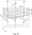
- Figure 9 and Figure 10 show a further embodiment in which the belt 9 in addition to those in the Fig.1 and Fig.2 shown belt layers 17,13, 14 and 15 is formed on the radially outer side of the outer working layer 15 with a further additional belt layer 16 which extends in the circumferential direction U over the entire circumference of the pneumatic vehicle tire and in the axial direction A of the pneumatic vehicle tire from left tire shoulder to the right Tire shoulder extends.
- the belt layer 16 extends over its entire axial extent in direct contact with the working position 15 and ends in the axial direction A with its two belt ply edges each in an axial position between the axial position of the nearest belt ply edge of the belt ply 14 and the axial position of the nearest belt ply edge of the fourth Belt layer (radially outer working position) 15 at an axial distance g from the belt ply edge of the belt ply 14 with g ⁇ d.
- the width f is the measure of the axial extent of the fifth belt ply 16 with b ⁇ f and with f ⁇ a. In the illustrated embodiment is b ⁇ f ⁇ c ⁇ a.
- illustrated embodiment is additionally f ⁇ h and g ⁇ k selected.
- illustrated embodiment is additionally h ⁇ f and k ⁇ g selected.
- the strength members 26 of the belt layer 16 are - as in Fig. 10 shown - aligned with an along the extension in the circumferential direction U of the tire opposite axial inclination direction as the strength member 27 of the belt layer 17.
- the strength members 26 are steel cords known type, for example, the type "1 + 5", the type “3 + 6", the type “3 + 8" or the type "3 + 9".
- FIG 11 and Figure 12 show a further alternative embodiment in which the belt 9 analogous to that in Figure 9 and Figure 10 shown and described for this purpose belt is formed. Only the positions of the belt layer 14 and 17 within the belt 9 are opposite to in the Figures 11 and 12 shown training reversed.
- the belt ply 14 in this embodiment is the second belt ply, which is positioned directly on the lower work ply 13 in touching contact with the lower work ply 13.
- the belt ply 17 forms the third belt ply and is positioned on the belt ply 14 between the belt ply 14 and the upper work ply 15 in touching contact with the belt ply 14 and the upper work ply 15.
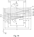
- Figure 13 and Figure 14 show a further alternative embodiment in which the belt 9 in addition to those in the Fig.1 and Fig.2 shown belt layers 13,17, 14 and 15 on the radial outside belt layer 14 between the belt layer of the belt layer 14 and the outer working position 15 is formed with an additional belt layer 19 which extends in the circumferential direction U over the entire circumference of the pneumatic vehicle tire and in the axial direction A of Pneumatic tire from left tire shoulder to the right tire shoulder extends.
- the belt ply 19 extends over its entire axial extent in direct contact with the outer working position 15 and ends in the axial direction A with its two belt ply edges each in an axial position between the axial position of the nearest belt ply edge of the belt ply 14 and the axial position of the nearest belt ply edge fourth belt layer (radially outer working position) 15 at an axial distance z from the belt ply edge of the belt ply 14 with z ⁇ d.
- the width s is the measure of the axial extent of the belt ply 19 with b ⁇ s and with s ⁇ c. In the illustrated embodiment, b ⁇ s ⁇ c ⁇ a is selected.
- the reinforcement 29 of the belt layer 19 are - as in Figure 14 shown - aligned with an along the extension in the circumferential direction U of the tire opposite axial inclination direction as the strength member 27 of the belt layer 17.
- the reinforcements 29 are steel cords known type, for example, the type "1 + 5", the type “3 + 6", the type “3 + 8" or the type "3 + 9".
- the strength members 27, the strength members 26, the strength members 28 and the strength members 29 are steel cords.
- the strength members 26 are suitable for use in commercial vehicle tires suitable hybrid cords known type in which filaments or yarns made of different materials, such as steel, polyamide, glass fiber, polyester or aramid.
- the strength members 27 are suitable for use in commercial vehicle tires hybrid cords known type in which filaments or yarns of different materials, such as steel, polyamide, glass fiber, polyester or aramid are made.
- Reinforcing member 28 suitable for use in commercial vehicle tires hybrid cords known type in which filaments or yarns made of different materials, such as steel, polyamide, glass fiber, polyester or aramid are made.
- the strength members 29 are suitable for use in commercial vehicle tires hybrid cords known type in which filaments or yarns made of different materials, such as steel, polyamide, glass fiber, polyester or aramid.
- the strength members 23 and / or the strength members 24 and / or reinforcing members 25 are suitable for use in commercial vehicle tires hybrid cords known type in which filaments or yarns of different materials, such as. Steel, polyamide, glass fiber, polyester or aramid are made.
- the angles ⁇ , ⁇ , ⁇ , ⁇ , ⁇ , ⁇ and ⁇ of the strength members 13, 14, 15, 16, 17, 19 and 18 respectively form the angle of inclination measured in the position of the equatorial plane.
Landscapes
- Engineering & Computer Science (AREA)
- Mechanical Engineering (AREA)
- Tires In General (AREA)
Claims (14)
- Pneumatique de véhicule pour véhicule utilitaire doté d'une carcasse (5), doté d'une ceinture (9) formée radialement à l'extérieur de la carcasse (5) et d'une bande de roulement (10) profilée formée radialement à l'extérieur de la ceinture (9) sur la ceinture (9), dans lequel la ceinture (9) est réalisée à partir d'au moins quatre couches de ceinture (17, 14, 13, 15) arrangées radialement en superposition de l'intérieur vers l'extérieur, dans lequel la première couche de ceinture (13), agencée le plus loin vers l'intérieur dans la direction radiale R parmi les quatre couches de ceinture (17, 14, 13, 15), est réalisée avec des supports de résistance (23) parallèles incrustés dans le caoutchouc, et la quatrième couche de ceinture (15), agencée le plus loin vers l'extérieur dans la direction radiale R, est réalisée avec des supports de résistance (25) parallèles incrustés dans le caoutchouc, dans lequel, dans la direction radiale entre la première couche de ceinture (13) et la quatrième couche de ceinture (15), au moins une deuxième couche de ceinture (14, 17), laquelle est agencée sur la première couche de ceinture (13), est réalisée avec des supports de résistance (24, 27) parallèles incrustés dans le caoutchouc et une troisième couche de ceinture (17, 14), laquelle est agencée sur la deuxième couche de ceinture (14, 17), est réalisée avec des supports de résistance (27, 24) parallèles incrustés dans le caoutchouc,
dans lequel la première couche de ceinture (13) et la quatrième couche de ceinture (15) sont des couches de travail, pour lesquelles les supports de résistance (23) de la première couche de ceinture (13) forment dans leur orientation un angle α par rapport à la direction circonférentielle U avec 10° ≤ α ≤ 45° et les supports de résistance (25) de la quatrième couche de ceinture (15) forment respectivement dans leur orientation un angle γ par rapport à la direction circonférentielle U avec 10° ≤ γ ≤ 45°, dans lequel en regardant dans la direction circonférentielle U du pneumatique de véhicule, les supports de résistance (23) de la première couche de ceinture (13) comportent une direction d'inclinaison axiale opposée aux supports de résistance (25) de la quatrième couche de ceinture (15), dans lequel la deuxième ou la troisième couche de ceinture est une couche de ceinture (17) dont les supports de résistance (27) forment dans leur orientation un angle ε par rapport à la direction circonférentielle U avec 40° ≤ ε ≤ 75°, et dans lequel l'autre des deux couches de ceinture est une couche de ceinture (14) dont les supports de résistance (24) forment dans leur orientation un angle β par rapport à la direction circonférentielle U avec 0° ≤ β ≤ 5°, caractérisé en ce
qu'une couche de ceinture supplémentaire (18) est agencée radialement à l'intérieur de la couche de travail (13) radialement intérieure entre la couche de travail (13) et la carcasse (5), avec des supports de résistance (28) parallèles incrustés dans le caoutchouc, formant dans leur orientation un angle θ par rapport à la direction circonférentielle U du pneumatique avec 40° ≤ θ ≤ 75° - en particulier θ = 50° - et dans lequel en particulier en regardant dans la direction circonférentielle U du pneumatique de véhicule, les supports de résistance (28) de cette couche de ceinture supplémentaire (18) comportent une direction d'inclinaison axiale opposée aux supports de résistance (27) de la couche de ceinture (17) formant dans leur orientation l'angle ε par rapport à la direction circonférentielle U. - Pneumatique de véhicule selon les caractéristiques de la revendication 1 ou 2, dans lequel la deuxième couche de ceinture est la couche de ceinture (17) dont les supports de résistance (27) forment dans leur orientation un angle ε par rapport à la direction circonférentielle U avec 40° ≤ ε ≤ 75°, et en ce que la troisième couche de ceinture est la couche de ceinture (14) dont les supports de résistance (24) forment dans leur orientation un angle β par rapport à la direction circonférentielle U avec 0° ≤ β ≤ 5°.
- Pneumatique de véhicule selon les caractéristiques de la revendication 2, dans lequel une couche de ceinture supplémentaire (19) est réalisée radialement à l'extérieur de la troisième couche de ceinture (14) entre la troisième et la quatrième couche de ceinture (15), dont les supports de résistance (29) forment dans leur orientation un angle (ζ) par rapport à la direction circonférentielle U avec 40° ≤ ζ ≤ 75°, dans lequel en regardant dans la direction circonférentielle U du pneumatique de véhicule, les supports de résistance (27) de la deuxième couche de ceinture (17) comportent une direction d'inclinaison axiale opposée aux supports de résistance (29) de la couche de ceinture supplémentaire (19).
- Pneumatique de véhicule selon les caractéristiques de la revendication 1, dans lequel la troisième couche de ceinture est la couche de ceinture (17) dont les supports de résistance (27) forment dans leur orientation un angle ε par rapport à la direction circonférentielle U avec 40° ≤ ε ≤ 75°, et en ce que la deuxième couche de ceinture est la couche de ceinture (14) dont les supports de résistance (24) forment dans leur orientation un angle β par rapport à la direction circonférentielle U avec 0° ≤ β ≤ 5°.
- Pneumatique de véhicule selon les caractéristiques de la revendication 1, dans lequel, en regardant dans la direction circonférentielle U, les supports de résistance (23) de la première couche de ceinture (13) et les supports de résistance (27) de la couche de ceinture (17) formant dans leur orientation l'angle ε par rapport à la direction circonférentielle U comportent la même direction d'inclinaison axiale.
- Pneumatique de véhicule selon les caractéristiques de la revendication 1, dans lequel la première couche de ceinture (13) est réalisée, dans son étendue axiale dans le pneumatique, de manière à être plus grande que toutes les autres couches de ceinture (14, 15, 17) de la ceinture.
- Pneumatique de véhicule selon les caractéristiques de la revendication 1, dans lequel la couche de ceinture (14) dont les supports de résistance (24) sont orientés dans leur orientation avec un angle β par rapport à la direction circonférentielle U, est réalisée dans son étendue axiale de manière à être plus petite que toutes les autres couches de ceinture (13, 15, 17) de la ceinture.
- Pneumatique de véhicule selon les caractéristiques d'une des revendications précédentes,
dans lequel une couche de ceinture supplémentaire (16) est agencée radialement à l'extérieur de la couche de travail (15) radialement extérieure sur la couche de travail extérieure (15), avec des supports de résistance (26) parallèles incrustés dans le caoutchouc, formant dans leur orientation un angle δ par rapport à la direction circonférentielle U du pneumatique avec 40° ≤ δ ≤ 75° - en particulier δ = 50° - et dans lequel en particulier en regardant dans la direction circonférentielle U du pneumatique de véhicule, les supports de résistance (26) de cette couche de ceinture supplémentaire (16) comportent une direction d'inclinaison axiale opposée aux supports de résistance (27) de la couche de ceinture (17) formant dans leur orientation l'angle ε par rapport à la direction circonférentielle U. - Pneumatique de véhicule selon les caractéristiques d'une ou de plusieurs des revendications précédentes, dans lequel les supports de résistance (23) de la première couche de ceinture (13) et les supports de résistance (25) de la quatrième couche de ceinture (15) sont des câbles d'acier.
- Pneumatique de véhicule selon les caractéristiques d'une ou de plusieurs des revendications précédentes, dans lequel les supports de résistance (23, 25) des première et quatrième couches de ceinture (13, 15) réalisées toutes les deux comme couches de travail sont réalisés comme élastiques dans le pneumatique avec un allongement D de D ≥ 0,2 % à 10 % de la force de rupture.
- Pneumatique de véhicule selon les caractéristiques d'une ou de plusieurs des revendications précédentes, dans lequel les supports de résistance (24) de la couche de ceinture (14) formant dans leur orientation l'angle β par rapport à la direction circonférentielle U sont des supports de résistance en acier.
- Pneumatique de véhicule selon les caractéristiques de la revendication une ou plusieurs des revendications précédentes,
dans lequel les supports de résistance (24) de la couche de ceinture (14) formant dans leur orientation l'angle β par rapport à la direction circonférentielle U sont des câbles en acier, possédant un allongement D avec D ≥ 0,2 % - en particulier avec D ≥ 1 % - à 10 % de la force de rupture. - Pneumatique de véhicule selon les caractéristiques d'une ou de plusieurs des revendications précédentes, dans lequel les supports de résistance (27) de la couche de ceinture (17) formant dans leur orientation l'angle ε par rapport à la direction circonférentielle U sont des câbles en acier.
- Pneumatique de véhicule selon les caractéristiques d'une ou de plusieurs des revendications précédentes, dans lequel les supports de résistance (26, 28, 29) des couches de ceinture (16, 18, 19) sont des câbles en acier.
Applications Claiming Priority (2)
| Application Number | Priority Date | Filing Date | Title |
|---|---|---|---|
| DE102014208728.7A DE102014208728A1 (de) | 2014-05-09 | 2014-05-09 | Fahrzeugluftreifen |
| PCT/EP2015/053056 WO2015169457A1 (fr) | 2014-05-09 | 2015-02-13 | Pneumatiques de véhicules |
Publications (2)
| Publication Number | Publication Date |
|---|---|
| EP3140132A1 EP3140132A1 (fr) | 2017-03-15 |
| EP3140132B1 true EP3140132B1 (fr) | 2019-08-28 |
Family
ID=52469844
Family Applications (1)
| Application Number | Title | Priority Date | Filing Date |
|---|---|---|---|
| EP15704308.4A Active EP3140132B1 (fr) | 2014-05-09 | 2015-02-13 | Pneumatiques de véhicules |
Country Status (3)
| Country | Link |
|---|---|
| EP (1) | EP3140132B1 (fr) |
| DE (1) | DE102014208728A1 (fr) |
| WO (1) | WO2015169457A1 (fr) |
Families Citing this family (2)
| Publication number | Priority date | Publication date | Assignee | Title |
|---|---|---|---|---|
| FR3044593B1 (fr) * | 2015-12-04 | 2017-12-08 | Michelin & Cie | Armature de sommet de pneumatique pour vehicule lourd de type genie civil |
| DE102020207242A1 (de) * | 2020-06-10 | 2021-12-16 | Continental Reifen Deutschland Gmbh | Fahrzeugluftreifen für Nutzfahrzeuge |
Family Cites Families (4)
| Publication number | Priority date | Publication date | Assignee | Title |
|---|---|---|---|---|
| DE102010000471A1 (de) * | 2010-02-19 | 2011-08-25 | Continental Reifen Deutschland GmbH, 30165 | Fahrzeugluftreifen |
| DE102010016569A1 (de) * | 2010-04-21 | 2011-10-27 | Continental Reifen Deutschland Gmbh | Fahrzeugluftreifen |
| DE102010016550A1 (de) * | 2010-04-21 | 2011-10-27 | Continental Reifen Deutschland Gmbh | Fahrzeugluftreifen |
| DE102011001228A1 (de) * | 2011-03-11 | 2012-09-13 | Continental Reifen Deutschland Gmbh | Fahrzeugluftreifen |
-
2014
- 2014-05-09 DE DE102014208728.7A patent/DE102014208728A1/de not_active Withdrawn
-
2015
- 2015-02-13 WO PCT/EP2015/053056 patent/WO2015169457A1/fr not_active Ceased
- 2015-02-13 EP EP15704308.4A patent/EP3140132B1/fr active Active
Non-Patent Citations (1)
| Title |
|---|
| None * |
Also Published As
| Publication number | Publication date |
|---|---|
| DE102014208728A1 (de) | 2015-11-12 |
| EP3140132A1 (fr) | 2017-03-15 |
| WO2015169457A1 (fr) | 2015-11-12 |
Similar Documents
| Publication | Publication Date | Title |
|---|---|---|
| EP3145729B1 (fr) | Pneumatique pour véhicules | |
| EP3083278B1 (fr) | Pneumatique de véhicule | |
| EP2683559B1 (fr) | Pneumatiques pour véhicule | |
| EP2560829B1 (fr) | Pneumatique de véhicule | |
| EP2536576B1 (fr) | Pneumatique de véhicule | |
| EP2560828B1 (fr) | Pneumatique de véhicule | |
| WO2012048930A1 (fr) | Pneumatique de véhicule | |
| WO2012055598A1 (fr) | Pneumatiques pour véhicule | |
| EP3083277B1 (fr) | Pneumatique de véhicule | |
| EP3140132B1 (fr) | Pneumatiques de véhicules | |
| EP3215374B1 (fr) | Pneumatique de véhicule | |
| EP2682279B1 (fr) | Pneus de véhicule | |
| EP2682281B1 (fr) | Pneus de véhicule | |
| EP3374202B1 (fr) | Pneumatiques de véhicule | |
| EP3019342B1 (fr) | Pneumatique de véhicule | |
| EP2078622A1 (fr) | Pneus de véhicule | |
| WO2014095100A1 (fr) | Pneumatique de véhicule |
Legal Events
| Date | Code | Title | Description |
|---|---|---|---|
| STAA | Information on the status of an ep patent application or granted ep patent |
Free format text: STATUS: THE INTERNATIONAL PUBLICATION HAS BEEN MADE |
|
| PUAI | Public reference made under article 153(3) epc to a published international application that has entered the european phase |
Free format text: ORIGINAL CODE: 0009012 |
|
| STAA | Information on the status of an ep patent application or granted ep patent |
Free format text: STATUS: REQUEST FOR EXAMINATION WAS MADE |
|
| 17P | Request for examination filed |
Effective date: 20161209 |
|
| AK | Designated contracting states |
Kind code of ref document: A1 Designated state(s): AL AT BE BG CH CY CZ DE DK EE ES FI FR GB GR HR HU IE IS IT LI LT LU LV MC MK MT NL NO PL PT RO RS SE SI SK SM TR |
|
| AX | Request for extension of the european patent |
Extension state: BA ME |
|
| DAX | Request for extension of the european patent (deleted) | ||
| GRAP | Despatch of communication of intention to grant a patent |
Free format text: ORIGINAL CODE: EPIDOSNIGR1 |
|
| STAA | Information on the status of an ep patent application or granted ep patent |
Free format text: STATUS: GRANT OF PATENT IS INTENDED |
|
| INTG | Intention to grant announced |
Effective date: 20190502 |
|
| GRAS | Grant fee paid |
Free format text: ORIGINAL CODE: EPIDOSNIGR3 |
|
| GRAA | (expected) grant |
Free format text: ORIGINAL CODE: 0009210 |
|
| STAA | Information on the status of an ep patent application or granted ep patent |
Free format text: STATUS: THE PATENT HAS BEEN GRANTED |
|
| AK | Designated contracting states |
Kind code of ref document: B1 Designated state(s): AL AT BE BG CH CY CZ DE DK EE ES FI FR GB GR HR HU IE IS IT LI LT LU LV MC MK MT NL NO PL PT RO RS SE SI SK SM TR |
|
| REG | Reference to a national code |
Ref country code: GB Ref legal event code: FG4D Free format text: NOT ENGLISH |
|
| REG | Reference to a national code |
Ref country code: CH Ref legal event code: EP |
|
| REG | Reference to a national code |
Ref country code: AT Ref legal event code: REF Ref document number: 1171952 Country of ref document: AT Kind code of ref document: T Effective date: 20190915 |
|
| REG | Reference to a national code |
Ref country code: IE Ref legal event code: FG4D Free format text: LANGUAGE OF EP DOCUMENT: GERMAN |
|
| REG | Reference to a national code |
Ref country code: DE Ref legal event code: R096 Ref document number: 502015010137 Country of ref document: DE |
|
| REG | Reference to a national code |
Ref country code: NL Ref legal event code: MP Effective date: 20190828 |
|
| REG | Reference to a national code |
Ref country code: LT Ref legal event code: MG4D |
|
| PG25 | Lapsed in a contracting state [announced via postgrant information from national office to epo] |
Ref country code: HR Free format text: LAPSE BECAUSE OF FAILURE TO SUBMIT A TRANSLATION OF THE DESCRIPTION OR TO PAY THE FEE WITHIN THE PRESCRIBED TIME-LIMIT Effective date: 20190828 Ref country code: NL Free format text: LAPSE BECAUSE OF FAILURE TO SUBMIT A TRANSLATION OF THE DESCRIPTION OR TO PAY THE FEE WITHIN THE PRESCRIBED TIME-LIMIT Effective date: 20190828 Ref country code: SE Free format text: LAPSE BECAUSE OF FAILURE TO SUBMIT A TRANSLATION OF THE DESCRIPTION OR TO PAY THE FEE WITHIN THE PRESCRIBED TIME-LIMIT Effective date: 20190828 Ref country code: PT Free format text: LAPSE BECAUSE OF FAILURE TO SUBMIT A TRANSLATION OF THE DESCRIPTION OR TO PAY THE FEE WITHIN THE PRESCRIBED TIME-LIMIT Effective date: 20191230 Ref country code: BG Free format text: LAPSE BECAUSE OF FAILURE TO SUBMIT A TRANSLATION OF THE DESCRIPTION OR TO PAY THE FEE WITHIN THE PRESCRIBED TIME-LIMIT Effective date: 20191128 Ref country code: LT Free format text: LAPSE BECAUSE OF FAILURE TO SUBMIT A TRANSLATION OF THE DESCRIPTION OR TO PAY THE FEE WITHIN THE PRESCRIBED TIME-LIMIT Effective date: 20190828 Ref country code: NO Free format text: LAPSE BECAUSE OF FAILURE TO SUBMIT A TRANSLATION OF THE DESCRIPTION OR TO PAY THE FEE WITHIN THE PRESCRIBED TIME-LIMIT Effective date: 20191128 Ref country code: FI Free format text: LAPSE BECAUSE OF FAILURE TO SUBMIT A TRANSLATION OF THE DESCRIPTION OR TO PAY THE FEE WITHIN THE PRESCRIBED TIME-LIMIT Effective date: 20190828 |
|
| PG25 | Lapsed in a contracting state [announced via postgrant information from national office to epo] |
Ref country code: IS Free format text: LAPSE BECAUSE OF FAILURE TO SUBMIT A TRANSLATION OF THE DESCRIPTION OR TO PAY THE FEE WITHIN THE PRESCRIBED TIME-LIMIT Effective date: 20191228 Ref country code: LV Free format text: LAPSE BECAUSE OF FAILURE TO SUBMIT A TRANSLATION OF THE DESCRIPTION OR TO PAY THE FEE WITHIN THE PRESCRIBED TIME-LIMIT Effective date: 20190828 Ref country code: AL Free format text: LAPSE BECAUSE OF FAILURE TO SUBMIT A TRANSLATION OF THE DESCRIPTION OR TO PAY THE FEE WITHIN THE PRESCRIBED TIME-LIMIT Effective date: 20190828 Ref country code: RS Free format text: LAPSE BECAUSE OF FAILURE TO SUBMIT A TRANSLATION OF THE DESCRIPTION OR TO PAY THE FEE WITHIN THE PRESCRIBED TIME-LIMIT Effective date: 20190828 Ref country code: GR Free format text: LAPSE BECAUSE OF FAILURE TO SUBMIT A TRANSLATION OF THE DESCRIPTION OR TO PAY THE FEE WITHIN THE PRESCRIBED TIME-LIMIT Effective date: 20191129 Ref country code: ES Free format text: LAPSE BECAUSE OF FAILURE TO SUBMIT A TRANSLATION OF THE DESCRIPTION OR TO PAY THE FEE WITHIN THE PRESCRIBED TIME-LIMIT Effective date: 20190828 |
|
| PG25 | Lapsed in a contracting state [announced via postgrant information from national office to epo] |
Ref country code: TR Free format text: LAPSE BECAUSE OF FAILURE TO SUBMIT A TRANSLATION OF THE DESCRIPTION OR TO PAY THE FEE WITHIN THE PRESCRIBED TIME-LIMIT Effective date: 20190828 |
|
| PG25 | Lapsed in a contracting state [announced via postgrant information from national office to epo] |
Ref country code: DK Free format text: LAPSE BECAUSE OF FAILURE TO SUBMIT A TRANSLATION OF THE DESCRIPTION OR TO PAY THE FEE WITHIN THE PRESCRIBED TIME-LIMIT Effective date: 20190828 Ref country code: PL Free format text: LAPSE BECAUSE OF FAILURE TO SUBMIT A TRANSLATION OF THE DESCRIPTION OR TO PAY THE FEE WITHIN THE PRESCRIBED TIME-LIMIT Effective date: 20190828 Ref country code: IT Free format text: LAPSE BECAUSE OF FAILURE TO SUBMIT A TRANSLATION OF THE DESCRIPTION OR TO PAY THE FEE WITHIN THE PRESCRIBED TIME-LIMIT Effective date: 20190828 Ref country code: EE Free format text: LAPSE BECAUSE OF FAILURE TO SUBMIT A TRANSLATION OF THE DESCRIPTION OR TO PAY THE FEE WITHIN THE PRESCRIBED TIME-LIMIT Effective date: 20190828 Ref country code: RO Free format text: LAPSE BECAUSE OF FAILURE TO SUBMIT A TRANSLATION OF THE DESCRIPTION OR TO PAY THE FEE WITHIN THE PRESCRIBED TIME-LIMIT Effective date: 20190828 |
|
| PG25 | Lapsed in a contracting state [announced via postgrant information from national office to epo] |
Ref country code: IS Free format text: LAPSE BECAUSE OF FAILURE TO SUBMIT A TRANSLATION OF THE DESCRIPTION OR TO PAY THE FEE WITHIN THE PRESCRIBED TIME-LIMIT Effective date: 20200224 Ref country code: CZ Free format text: LAPSE BECAUSE OF FAILURE TO SUBMIT A TRANSLATION OF THE DESCRIPTION OR TO PAY THE FEE WITHIN THE PRESCRIBED TIME-LIMIT Effective date: 20190828 Ref country code: SK Free format text: LAPSE BECAUSE OF FAILURE TO SUBMIT A TRANSLATION OF THE DESCRIPTION OR TO PAY THE FEE WITHIN THE PRESCRIBED TIME-LIMIT Effective date: 20190828 Ref country code: SM Free format text: LAPSE BECAUSE OF FAILURE TO SUBMIT A TRANSLATION OF THE DESCRIPTION OR TO PAY THE FEE WITHIN THE PRESCRIBED TIME-LIMIT Effective date: 20190828 |
|
| REG | Reference to a national code |
Ref country code: DE Ref legal event code: R097 Ref document number: 502015010137 Country of ref document: DE |
|
| PLBE | No opposition filed within time limit |
Free format text: ORIGINAL CODE: 0009261 |
|
| STAA | Information on the status of an ep patent application or granted ep patent |
Free format text: STATUS: NO OPPOSITION FILED WITHIN TIME LIMIT |
|
| PG2D | Information on lapse in contracting state deleted |
Ref country code: IS |
|
| 26N | No opposition filed |
Effective date: 20200603 |
|
| PG25 | Lapsed in a contracting state [announced via postgrant information from national office to epo] |
Ref country code: SI Free format text: LAPSE BECAUSE OF FAILURE TO SUBMIT A TRANSLATION OF THE DESCRIPTION OR TO PAY THE FEE WITHIN THE PRESCRIBED TIME-LIMIT Effective date: 20190828 |
|
| REG | Reference to a national code |
Ref country code: CH Ref legal event code: PL |
|
| GBPC | Gb: european patent ceased through non-payment of renewal fee |
Effective date: 20200213 |
|
| REG | Reference to a national code |
Ref country code: BE Ref legal event code: MM Effective date: 20200229 |
|
| PG25 | Lapsed in a contracting state [announced via postgrant information from national office to epo] |
Ref country code: MC Free format text: LAPSE BECAUSE OF FAILURE TO SUBMIT A TRANSLATION OF THE DESCRIPTION OR TO PAY THE FEE WITHIN THE PRESCRIBED TIME-LIMIT Effective date: 20190828 Ref country code: LU Free format text: LAPSE BECAUSE OF NON-PAYMENT OF DUE FEES Effective date: 20200213 |
|
| PG25 | Lapsed in a contracting state [announced via postgrant information from national office to epo] |
Ref country code: LI Free format text: LAPSE BECAUSE OF NON-PAYMENT OF DUE FEES Effective date: 20200229 Ref country code: CH Free format text: LAPSE BECAUSE OF NON-PAYMENT OF DUE FEES Effective date: 20200229 |
|
| PG25 | Lapsed in a contracting state [announced via postgrant information from national office to epo] |
Ref country code: FR Free format text: LAPSE BECAUSE OF NON-PAYMENT OF DUE FEES Effective date: 20200229 Ref country code: GB Free format text: LAPSE BECAUSE OF NON-PAYMENT OF DUE FEES Effective date: 20200213 Ref country code: IE Free format text: LAPSE BECAUSE OF NON-PAYMENT OF DUE FEES Effective date: 20200213 |
|
| PG25 | Lapsed in a contracting state [announced via postgrant information from national office to epo] |
Ref country code: BE Free format text: LAPSE BECAUSE OF NON-PAYMENT OF DUE FEES Effective date: 20200229 |
|
| REG | Reference to a national code |
Ref country code: AT Ref legal event code: MM01 Ref document number: 1171952 Country of ref document: AT Kind code of ref document: T Effective date: 20200213 |
|
| PG25 | Lapsed in a contracting state [announced via postgrant information from national office to epo] |
Ref country code: AT Free format text: LAPSE BECAUSE OF NON-PAYMENT OF DUE FEES Effective date: 20200213 |
|
| PG25 | Lapsed in a contracting state [announced via postgrant information from national office to epo] |
Ref country code: MT Free format text: LAPSE BECAUSE OF FAILURE TO SUBMIT A TRANSLATION OF THE DESCRIPTION OR TO PAY THE FEE WITHIN THE PRESCRIBED TIME-LIMIT Effective date: 20190828 Ref country code: CY Free format text: LAPSE BECAUSE OF FAILURE TO SUBMIT A TRANSLATION OF THE DESCRIPTION OR TO PAY THE FEE WITHIN THE PRESCRIBED TIME-LIMIT Effective date: 20190828 |
|
| PG25 | Lapsed in a contracting state [announced via postgrant information from national office to epo] |
Ref country code: MK Free format text: LAPSE BECAUSE OF FAILURE TO SUBMIT A TRANSLATION OF THE DESCRIPTION OR TO PAY THE FEE WITHIN THE PRESCRIBED TIME-LIMIT Effective date: 20190828 |
|
| REG | Reference to a national code |
Ref country code: DE Ref legal event code: R081 Ref document number: 502015010137 Country of ref document: DE Owner name: CONTINENTAL REIFEN DEUTSCHLAND GMBH, DE Free format text: FORMER OWNER: CONTINENTAL REIFEN DEUTSCHLAND GMBH, 30165 HANNOVER, DE |
|
| PGFP | Annual fee paid to national office [announced via postgrant information from national office to epo] |
Ref country code: DE Payment date: 20260228 Year of fee payment: 12 |