EP3140171B1 - Système pneumatique de freins pour véhicule et procédé d'application d'un tel système - Google Patents
Système pneumatique de freins pour véhicule et procédé d'application d'un tel système Download PDFInfo
- Publication number
- EP3140171B1 EP3140171B1 EP15715169.7A EP15715169A EP3140171B1 EP 3140171 B1 EP3140171 B1 EP 3140171B1 EP 15715169 A EP15715169 A EP 15715169A EP 3140171 B1 EP3140171 B1 EP 3140171B1
- Authority
- EP
- European Patent Office
- Prior art keywords
- brake
- wheel
- pressure
- valve
- wheel brake
- Prior art date
- Legal status (The legal status is an assumption and is not a legal conclusion. Google has not performed a legal analysis and makes no representation as to the accuracy of the status listed.)
- Active
Links
Images


Classifications
-
- B—PERFORMING OPERATIONS; TRANSPORTING
- B60—VEHICLES IN GENERAL
- B60T—VEHICLE BRAKE CONTROL SYSTEMS OR PARTS THEREOF; BRAKE CONTROL SYSTEMS OR PARTS THEREOF, IN GENERAL; ARRANGEMENT OF BRAKING ELEMENTS ON VEHICLES IN GENERAL; PORTABLE DEVICES FOR PREVENTING UNWANTED MOVEMENT OF VEHICLES; VEHICLE MODIFICATIONS TO FACILITATE COOLING OF BRAKES
- B60T13/00—Transmitting braking action from initiating means to ultimate brake actuator with power assistance or drive; Brake systems incorporating such transmitting means, e.g. air-pressure brake systems
- B60T13/10—Transmitting braking action from initiating means to ultimate brake actuator with power assistance or drive; Brake systems incorporating such transmitting means, e.g. air-pressure brake systems with fluid assistance, drive, or release
- B60T13/66—Electrical control in fluid-pressure brake systems
- B60T13/68—Electrical control in fluid-pressure brake systems by electrically-controlled valves
- B60T13/683—Electrical control in fluid-pressure brake systems by electrically-controlled valves in pneumatic systems or parts thereof
-
- B—PERFORMING OPERATIONS; TRANSPORTING
- B60—VEHICLES IN GENERAL
- B60T—VEHICLE BRAKE CONTROL SYSTEMS OR PARTS THEREOF; BRAKE CONTROL SYSTEMS OR PARTS THEREOF, IN GENERAL; ARRANGEMENT OF BRAKING ELEMENTS ON VEHICLES IN GENERAL; PORTABLE DEVICES FOR PREVENTING UNWANTED MOVEMENT OF VEHICLES; VEHICLE MODIFICATIONS TO FACILITATE COOLING OF BRAKES
- B60T13/00—Transmitting braking action from initiating means to ultimate brake actuator with power assistance or drive; Brake systems incorporating such transmitting means, e.g. air-pressure brake systems
- B60T13/10—Transmitting braking action from initiating means to ultimate brake actuator with power assistance or drive; Brake systems incorporating such transmitting means, e.g. air-pressure brake systems with fluid assistance, drive, or release
- B60T13/24—Transmitting braking action from initiating means to ultimate brake actuator with power assistance or drive; Brake systems incorporating such transmitting means, e.g. air-pressure brake systems with fluid assistance, drive, or release the fluid being gaseous
- B60T13/26—Compressed-air systems
- B60T13/268—Compressed-air systems using accumulators or reservoirs
-
- B—PERFORMING OPERATIONS; TRANSPORTING
- B60—VEHICLES IN GENERAL
- B60T—VEHICLE BRAKE CONTROL SYSTEMS OR PARTS THEREOF; BRAKE CONTROL SYSTEMS OR PARTS THEREOF, IN GENERAL; ARRANGEMENT OF BRAKING ELEMENTS ON VEHICLES IN GENERAL; PORTABLE DEVICES FOR PREVENTING UNWANTED MOVEMENT OF VEHICLES; VEHICLE MODIFICATIONS TO FACILITATE COOLING OF BRAKES
- B60T15/00—Construction arrangement, or operation of valves incorporated in power brake systems and not covered by groups B60T11/00 or B60T13/00
- B60T15/02—Application and release valves
- B60T15/025—Electrically controlled valves
- B60T15/027—Electrically controlled valves in pneumatic systems
-
- B—PERFORMING OPERATIONS; TRANSPORTING
- B60—VEHICLES IN GENERAL
- B60T—VEHICLE BRAKE CONTROL SYSTEMS OR PARTS THEREOF; BRAKE CONTROL SYSTEMS OR PARTS THEREOF, IN GENERAL; ARRANGEMENT OF BRAKING ELEMENTS ON VEHICLES IN GENERAL; PORTABLE DEVICES FOR PREVENTING UNWANTED MOVEMENT OF VEHICLES; VEHICLE MODIFICATIONS TO FACILITATE COOLING OF BRAKES
- B60T8/00—Arrangements for adjusting wheel-braking force to meet varying vehicular or ground-surface conditions, e.g. limiting or varying distribution of braking force
- B60T8/17—Using electrical or electronic regulation means to control braking
- B60T8/172—Determining control parameters used in the regulation, e.g. by calculations involving measured or detected parameters
-
- B—PERFORMING OPERATIONS; TRANSPORTING
- B60—VEHICLES IN GENERAL
- B60T—VEHICLE BRAKE CONTROL SYSTEMS OR PARTS THEREOF; BRAKE CONTROL SYSTEMS OR PARTS THEREOF, IN GENERAL; ARRANGEMENT OF BRAKING ELEMENTS ON VEHICLES IN GENERAL; PORTABLE DEVICES FOR PREVENTING UNWANTED MOVEMENT OF VEHICLES; VEHICLE MODIFICATIONS TO FACILITATE COOLING OF BRAKES
- B60T8/00—Arrangements for adjusting wheel-braking force to meet varying vehicular or ground-surface conditions, e.g. limiting or varying distribution of braking force
- B60T8/32—Arrangements for adjusting wheel-braking force to meet varying vehicular or ground-surface conditions, e.g. limiting or varying distribution of braking force responsive to a speed condition, e.g. acceleration or deceleration
- B60T8/34—Arrangements for adjusting wheel-braking force to meet varying vehicular or ground-surface conditions, e.g. limiting or varying distribution of braking force responsive to a speed condition, e.g. acceleration or deceleration having a fluid pressure regulator responsive to a speed condition
- B60T8/36—Arrangements for adjusting wheel-braking force to meet varying vehicular or ground-surface conditions, e.g. limiting or varying distribution of braking force responsive to a speed condition, e.g. acceleration or deceleration having a fluid pressure regulator responsive to a speed condition including a pilot valve responding to an electromagnetic force
Definitions
- the invention relates to a pneumatic braking device for motor vehicles according to the preamble of claim 1.
- the invention also relates to a method for operating a pneumatic braking device for motor vehicles according to the preamble of claim 10.
- Pneumatic braking devices for motor vehicles usually have a pneumatically actuatable wheel brake for each wheel of the motor vehicle, the pneumatic operating means for the wheel brakes being made available in a pressure accumulator under static pressure.
- the braking devices have a brake signal transmitter which is coupled to the movement of a brake pedal which can be actuated by the driver of the motor vehicle and which generates a braking request signal when the brake pedal is actuated.
- a target brake pressure is set at the wheel brakes as a function of the brake request signal.
- EP 2 077 215 A1 discloses such a pneumatic braking device for motor vehicles, each having an electrically controllable wheel brake module per wheel for setting the target brake pressure of the respective wheel brake.
- An electronic control unit determines preset values for the target brake pressures for the wheel brakes, taking into account the brake signal transmitter, the preset values for the target brake pressures being preset for the wheel brake modules.
- the known pneumatic braking device provides both embodiments with a common wheel brake module for both wheel brakes of an axle, and an embodiment in which the wheels of an axle are each equipped with a wheel brake module.
- the wheel brake modules include at least one ventilation valve and one ventilation valve, the ventilation valve being actuated to activate the wheel brake.
- the ventilation valve being actuated to activate the wheel brake.
- wheel brake modules include electrically actuatable activation means which can be controlled by a control logic via an actuating signal.
- the control logic includes means for generating an actuating signal for the activation means in accordance with the default value for the target brake pressure.
- relay valves are provided for both ventilation and bleeding, whereby the control pressure for actuating the valves, in particular the ventilation valve, is decoupled from the operating pressure of the wheel brakes.
- DE 10 2010 010 606 A1 discloses a pressure control device of a pressure medium brake system of a vehicle for individual wheel control of brake pressures in brake cylinders of wheels of an axle. Each side of the vehicle is assigned a 2/2-way valve which, depending on its position, blocks access to the brake cylinder. Each 2/2-way valve is connected to one of the working connections of a relay valve of the known pressure control device, a supply connection being supplied with supply pressure and a vent connection being connected to a pressure sink.
- the control connection of the relay valve can be connected by means of a 3/2-way solenoid valve or a valve device with two 2/2-way valves, which can be controlled by the control unit, either with a brake control pressure, with a supply pressure or with a pressure sink.
- the invention is based on the object of reducing the manufacturing costs and the size of the pneumatic braking device with wheel brake modules for both wheels of an axle of a motor vehicle.
- this object is achieved by a pneumatic braking device with the features of claim 1.
- the object is also achieved by a method for operating a pneumatic brake system having the features of claim 11.
- the ventilation valve and its activation means are designed such that the pneumatic pressure from the supply pressure accumulator in the actuated state of the ventilation valve is transmitted directly to the respective wheel brake is controllable.
- the vent valve and its activation means are designed such that the brake pressure of the wheel brake is vented directly into the atmosphere when the vent valve is actuated. If, for cost reasons, separate wheel brake modules are provided for both wheels of an axle instead of a common wheel brake module, several of the previously required relay valves are replaced according to the invention by controlling the pneumatic pressure from the supply pressure accumulator directly to the respective wheel brake. In this way, the size of the braking device and, by reducing the number of components, also the production costs can be reduced.
- the control of the pneumatic pressure from the supply pressure accumulator means that when the ventilation valve opens, the pneumatic pressure from the supply pressure accumulator acts directly on the wheel brake or the pneumatic cylinder formed in the wheel brake.
- the actuation of the ventilation valve itself takes place by electrically actuatable activation means.
- the activation means of the ventilation valve comprises an electrically actuatable ventilation pilot valve by means of which the ventilation valve can be actuated.
- the pilot valve opens upon electrical actuation and, in a preferred embodiment of the invention, switches the pneumatic pressure in the supply pressure accumulator to the actuating element of the ventilation valve, whereby the pneumatically actuated opens.
- the ventilation valve and its electrically operated ventilation pilot valve form a ventilation valve group in which the pneumatic pressure from the supply pressure accumulator is used indirectly to actuate the ventilation valve, but the pneumatic pressure is nevertheless switched through directly to the wheel brake.
- the activation means of the vent valve is also equipped with an electrically actuatable vent pilot valve, by means of which the vent valve can be actuated.
- the venting pilot valve or the venting pilot valve is designed in an advantageous embodiment as an electrically actuatable solenoid valve.
- a rapid pressure build-up in the brake cylinder is achieved if the control logic of the wheel brake module comprises means for generating a pulse-modulated actuating signal for the electrical activation means, in particular the ventilation pilot valve.
- a pulse-modulated signal is understood to mean a time-discrete signal sequence consisting of individual pulses, the activation means being switched on and off for short intervals in accordance with the time-discrete signal sequence.
- the activation means as a pilot valve
- the pilot valve is switched on and off in rapid succession with the pulse-modulated actuating signal of the control logic, with a rapid pressure build-up in the wheel brake being achieved through a suitable pulse pattern of the modulation.
- the activation means of the vent valve is also controlled with a pulse-modulated control signal corresponding to the activation of the vent valve.
- each wheel brake module is therefore assigned a characteristic map determined in advance for the respective wheel brake module, which includes information on time-discrete signal sequences for the control signal as a function of setpoint brake pressures.
- the determination of an individual map for each wheel brake module takes into account minor differences, for example geometric differences in the entire volume of the valve assembly including, if applicable, the brake cylinder and includes optimized signal sequences or pulse schemes for an individual wheel brake module, in which the fastest possible target brake pressure builds up.
- optimized pulse schemes or time-discrete signal sequences for the pulse-modulated control signal are determined for different setpoint braking pressures and made available, for example, in a memory element of the control logic.
- the wheel brake module is therefore, as it were, taught-in before the first start-up when determining the characteristic map with optimal time-discrete signal sequences as a function of setpoint brake pressures.
- the control logic for the activation means is advantageously designed as a control circuit for adjusting the setpoint brake pressure, which takes into account the sensor signal of a pressure sensor in a pressure medium line between the ventilation valve and the wheel brake as the actual brake pressure.
- the pulse pattern of the pulse-modulated control signal is varied as a manipulated variable for adapting the actual brake pressure to the desired target brake pressure.
- Pulse-width modulated control signals are particularly advantageously generated, with the variation the pulse width the characteristics of the pressure build-up can be influenced. For example, by lengthening the pulse width, that is to say the duration of the interval during which the activation means is actuated, a steeper gradient in the pressure build-up is usually achieved.
- a superimposed control loop for calculating and adapting the default values for the target brake pressure, taking into account a continuously ascertainable driving state variable.
- the superimposed control loop is used to adapt the specified target brake pressure to the specific driving behavior of the vehicle, which counteracts any skewing of the vehicle during a braking process. A tendency of the vehicle to skew is recognized by taking into account the continuously ascertained driving state variable and counteracted by appropriate adjustment or adjustment of the target brake pressures for the different wheel brake modules.
- the superimposed control circuit for calculating and adapting the default values for the target brake pressure thus adapts the target brake pressure, as it was initially determined according to the actuation of the brake signal transmitter, to any circumstances that may tend to pull crooked.
- a superimposed control loop takes into account a measured wheel speed as a driving state variable. If the measured wheel speeds of the two wheels to which the wheel brake modules are assigned deviate from one another, it can be concluded that there is a tendency towards skewing.
- the superimposed control circuit adjusts the default values for the target brake pressure of the respective wheel brake modules.
- a superimposed control loop which takes into account a yaw rate of the motor vehicle as a driving state variable.
- several superimposed control loops are provided for calculating and adapting the default values for the target brake pressure, whereby the default value from which the pulse-modulated control signal is calculated is further optimized.
- Suitable driving state variables can be made available, for example, from the control units of driver assistance systems.
- the motor vehicle with the braking device according to the invention is preferably a truck, for example tractors or omnibuses.
- Fig. 1 shows schematically a section of a pneumatic braking device 1 for motor vehicles, namely a two-axle truck 2.
- a left front wheel 3 and a right front wheel 4 on a front axle 5 and a left rear wheel 6 and a right rear wheel 7 are shown in the schematic illustration a rear axle 8 is shown.
- the pneumatic braking device 1 comprises a pneumatic wheel brake 9 for each wheel 3, 4, 6, 7.
- the wheel brakes 9 each have a brake cylinder to which braking pressure can be applied via a pressure medium line 10 in order to activate the wheel brake 9.
- the pneumatic braking device 1 comprises one or more supply pressure accumulators 11.
- a electrically controllable wheel brake module 12, 13, which influences the build-up of brake pressure in the respective wheel brake 9 in the manner described in more detail below.
- a wheel brake module 12, 13 is assigned to each wheel 3, 4 of the front axle 5.
- a first wheel brake module 12 accordingly influences the braking behavior of the left front wheel 3, while a second wheel brake module 13 influences the braking behavior of the right front wheel 4.
- the braking device 1 also includes a brake signal transmitter 14, which preferably has a pedal in the cab of the driver's cab of the motor vehicle 2 and can be operated by a driver.
- the brake signal generator 14 generates a brake signal 15 when the pedal is pressed ( Fig. 7 ), which represents the driver's braking request.
- the brake signal transmitter 14 is connected to an electronic control unit 17 via a brake signal line 16 in a signal-transmitting manner.
- the electronic control unit 17 is designed to determine preset values of setpoint brake pressures of the wheel brakes 9, taking into account the brake signal transmitter 14.
- the electronic control unit 17 is connected to transmit signals both to the first wheel brake module 12 for the left front wheel 3 and to the second wheel brake module 13 for the right front wheel 4.
- Each wheel brake 9 is assigned a pressure sensor 18 which determines the current actual brake pressure in the respective wheel brake 9.
- Each wheel brake module 12, 13 uses the current actual brake pressure of its respective wheel brake 9 to regulate a specific setpoint brake pressure.
- the pressure sensor 18 is connected to the respective wheel brake module 12, 13 in a signal-transmitting manner and can also be structurally combined with the respective wheel brake module 12, 13.
- FIG. 13 shows a pneumatic diagram of a wheel brake module 12.
- the same reference numerals are used for the same components as in FIG Fig. 1 used.
- the wheel brake module 12 controls the fluidic connection of a wheel brake 9 of a wheel 3 with a supply pressure accumulator 11 and has a ventilation valve 19 and a ventilation valve 20.
- the ventilation valve 19 controls the pneumatic pressure from the supply pressure accumulator 11 directly to the wheel brake 9.
- the ventilation valve 19 and the ventilation valve 20 are designed as 2/2-way valves in the exemplary embodiment shown and can thus be switched between an open and a closed position.
- the ventilation valve 19 has a supply connection 21, which is connected to a working connection 22 in the open position of the ventilation valve.
- the vent valve comprises a supply connection 23 which, for venting the wheel brake 9, can be connected to the working connection 24, which opens into the atmosphere.
- the supply connection 21 of the ventilation valve 19 is connected to the pressure reservoir 11, that is, there is a direct fluidic connection.
- the working connection 22 of the ventilation valve 19 communicates directly with the wheel brake 9, which ensures direct control when the ventilation valve 19 is in the open state.
- Each wheel brake module 12 also includes electrically actuable activation means 25 for activating the ventilation valve 19 and / or the ventilation valve 20.
- the ventilation valve 19 can therefore be activated indirectly via electrical actuation, whereby the pneumatic pressure of the pressure reservoir 11 is controlled directly to the wheel brake 9.
- a control logic 26 is assigned to the wheel brake module 12 of an actuating signal 36 for the activation means 25 corresponding to the preset value for the setpoint brake pressure.
- the control logic 26 is provided individually for each wheel brake module 12 of each wheel 3.
- the actual value of the brake pressure in the pressure medium line 10 to the wheel brake 9 is continuously given to the control logic 26 by the pressure sensor 18.
- the electronics of the control logic 26 can be accommodated in the wheel brake module.
- the electronic control unit 17 ( Fig. 1 ) Electronic equipment for the control logics 26 of the connected wheel brake modules 12, 13.
- a mutual exchange of information in particular the transmission of control signals and sensor signals via a bus system (CAN), is possible.
- the ventilation valve 19 and the ventilation valve 20 are designed as pneumatically actuated valves.
- the activating means 25 is shown in FIG Fig. 2 an electrically operated pilot valve is provided in each case.
- the working connection 28 of a ventilation pilot valve 29 is connected to a pneumatic control input 27 of the ventilation valve 19.
- the supply connection 30 of the ventilation pilot valve 29 communicates with a pneumatic pressure reservoir, in the exemplary embodiment shown, the pressure reservoir 11.
- the electrical control input 31 of the ventilation pilot valve can be acted upon by the control logic 26 via a corresponding electrical actuating signal. If the ventilation pilot valve 29 is opened, the ventilation pilot valve 29 connects the supply pressure accumulator 11 to the pneumatic control input 27 of the ventilation valve 19 and provides a direct switching through of the pneumatic pressure from the supply pressure accumulator 11 to the wheel brake 9.
- the activation means of the vent valve 20 comprises an electrically actuatable vent pilot valve 32, the working connection 33 of which acts on the pneumatic control input 55 of the vent valve 20.
- a supply connection 34 of the venting pilot valve 32 like the other pilot valve of the activating means 25, is connected to the supply pressure accumulator 11.
- the electrical control input 35 of the venting pilot valve 32 can be controlled via the control logic 26.
- stepping motors for actuation are assigned to the vent valve 19 and / or the vent valve 20 as electrically actuatable activation devices.
- the control logic 26 generates a pulse-modulated control signal for the ventilation pilot valve 29.
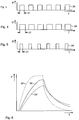
- the wheel brake modules 12, 13 are actuated via pulse-width modulated control signals. Examples of the time courses of such pulse-width modulated control signals are given in Figs. 3 to 5 shown.
- Fig. 3 shows an exemplary embodiment of a pulse-width modulated actuating signal 36 with a predetermined pulse width 37.
- Fig. 4 is the time course of an actuating signal 38 with a relative to the actuating signal 36 in Fig. 3 enlarged pulse width 37 shown.
- the pulse width 37 is in relation to the control signal 36 in Fig. 3 decreased.
- a pulse-width modulated control signal with a specific pulse width enables a rapid pressure build-up in the respective wheel brake.
- the influence the change in the pulse width 37 is in the time course of the pressure build-up in Fig. 6 shown.
- an actuating signal 38 with an enlarged pulse width there is a steeper gradient in the pressure build-up and an overall more rapid pressure build-up than with a smaller pulse width.
- the optimal pulse width for the specific braking situation is continuously determined by the control logic.
- the pulse pattern with a specific pulse width corresponding to a specific pressure rise behavior is determined during operation of the braking device as shown below.
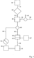
- Fig. 7 shows a block diagram for operating the pneumatic braking device.
- the electronic control unit 17 determines, in a default step 40, default values 41 of the setpoint braking pressures of the wheel brakes, taking into account the brake signal transmitter 14, which feeds its brake signal 15 to the control unit.
- the default value 41 for the target brake pressure is used for an actual / target value comparison 43, with a control deviation from the actual value 44 of the brake pressure in the wheel brake, which is continuously measured by the pressure sensor 18, and the target value of the brake pressure 45 is determined.
- the control deviation 45 is specified to a controller 46 which, taking into account the modulation 42, generates the pulse-width-modulated control signal 36.
- a control intervention to adjust the actual value 44 of the brake pressure to the setpoint value takes place by varying the pulse width of the control signal 36.
- the control signal 36 is used to set the pilot control ventilation valve 29 of the respective wheel brake module 12 ( Fig. 2 ) controlled.
- a similar control loop is provided for controlling the setpoint brake pressure of the other wheel brake module 13 of the front axle of the truck.
- the control loop for adjusting the actual value 44 of the brake pressure to the setpoint value is part of the control logic of the respective wheel brake module 12, 13.
- Each control logic 26 ( Fig. 2 ) the respective wheel brake module 12, 13 is assigned a map 47 determined in advance for the respective wheel brake module, which includes information on time-discrete signal sequences for the control signal 36 as a function of target brake pressures.
- the characteristics map 47 is the result of a learning process of the wheel brake module, which is determined before the first system initialization, for example through test bench tests.
- the respective wheel brake module 12, 13 is determined for certain target brake pressures, optimal pulse schemes for the pulse-width modulated control signal.
- the pulse schemes of different wheel brake modules usually differ from one another, since geometrical influencing factors such as cylinder sizes or piping are taken into account when teaching-in, and characteristic maps that are individually optimized for the wheel brake modules are taught.
- the optimized pulse schemes for the respective target brake pressures are stored as default parameters as a characteristic map, for example in an EEPROM.
- a pulse scheme is read out from the respective characteristic map 47 of the wheel brake module and a corresponding pulse-width-modulated control signal 36 is generated. If a control deviation 45 is determined when adjusting the brake pressure, then the desired target brake pressure is adjusted by varying the pulse width.
- At least one superimposed control circuit 48 is provided for calculating and adapting the default values for the target brake pressure, taking into account a continuously ascertainable driving state variable 49.
- the continuously determined driving state variable 49 is a parameter that characterizes the movement of the truck.
- a superimposed control loop 48 is provided which takes into account a measured wheel speed as a driving state variable. The wheel speed is measured by a sensor device ( Fig. 1 ) is provided, which consists of a pole wheel 51 rotating with the front wheel 4 and a sensor 52 cooperating with the pole wheel 51.
- a superimposed control loop which takes into account a yaw rate of the motor vehicle as a driving state variable.
- a plurality of superimposed control loops with different driving state variables are provided, so that the occurrence of tendencies in the motor vehicle to skew are virtually excluded.
- a control deviation is formed from the specified measured value of the driving state variable 49 and a setpoint value, or a correction factor 53 with which the setpoint 41 can be adapted to the respective dynamic driving situation.
- the setpoint value 54 which is used for comparison with the measured driving state variable 49, can be specified from a memory element are or is derived by comparison with the corresponding measured variable of the other wheel brake module.
- the actual pressure from the wheel brake module of another wheel is used to regulate the brake pressure.
- the pressure sensors 18 of the respective wheel brake modules 12, 13 are networked to transmit signals.
- the wheel brake modules 12, 13 determine the brake pressure in their respective wheel brakes on the basis of the Control the default value of the target brake pressure. In the case of a control of the brake pressure of the respective wheel brake, any tendency to skew is counteracted by the superimposed control loops 48.
Landscapes
- Engineering & Computer Science (AREA)
- Transportation (AREA)
- Mechanical Engineering (AREA)
- Physics & Mathematics (AREA)
- Electromagnetism (AREA)
- Fluid Mechanics (AREA)
- Regulating Braking Force (AREA)
- Braking Systems And Boosters (AREA)
Claims (17)
- Système de frein pneumatique pour véhicules automobiles (2), comprenant un générateur de signal de frein (14), un accumulateur de pression de réserve (11) et un frein de roue (9) à commande pneumatique pour chaque roue (3, 4) ainsi qu'au moins un essieu (5) du véhicule automobile (2) comprenant à chaque fois un module de frein de roue à commande électrique (12, 13) pour chaque roue (3, 4) pour l'ajustement d'une pression de frein de consigne du frein de roue respectif (9), ainsi qu'une unité de commande électronique (17) pour déterminer des valeurs prédéfinissables (41) des pressions de frein de consigne des freins de roues (9) en tenant compte du générateur de signal de frein (14), lesquelles valeurs prédéfinissables peuvent être prédéfinies pour les modules de frein de roue (12, 13), chaque module de frein de roue (12, 13) comprenant :- au moins une soupape de ventilation (19) et une soupape de désaérage (20),- un moyen d'activation à commande électrique (25) pour activer la soupape de ventilation (19) et/ou la soupape de désaérage (20),- une logique de commande (26) comprenant des moyens pour générer un signal de commande (36) pour le moyen d'activation (25), correspondant à la valeur prédéfinissable (41) pour la pression de frein de consigne, caractérisé en ce que la soupape de désaérage (20) et son moyen d'activation sont réalisés de telle sorte que la pression pneumatique peut être commandée à partir de l'accumulateur de pression de réserve (11) dans l'état actionné de la soupape de ventilation (19), directement vers le frein de roue respectif (9) et/ou la soupape de désaérage (20) évacue la pression de frein au niveau du frein de roue (9) dans l'état actionné directement vers l'atmosphère.
- Système de frein selon la revendication 1, caractérisé en ce que le moyen d'activation de la soupape de ventilation (19) comprend une soupape pilote de ventilation à commande électrique (29) au moyen de laquelle la soupape de ventilation (19) peut être actionnée.
- Système de frein selon la revendication 2, caractérisé en ce que la logique de commande (26) du module de frein de roue (12, 13) comprend des moyens pour générer un signal de commande à modulation d'impulsion (36) pour la soupape pilote de ventilation (29), la logique de commande (26) de chaque module de frein de roue (12, 13) étant associée à un champ caractéristique (47) déterminé au préalable pour le module de frein de roue respectif (12, 13), lequel champ caractéristique comprend des informations concernant des successions de signaux distinctes dans le temps pour le signal de commande (36) en fonction de pressions de frein de consigne.
- Système de frein selon la revendication 3, caractérisé en ce que la logique de commande (26) pour les moyens d'activation est réalisée sous forme de circuit de réglage pour ajuster la pression de frein de consigne, lequel tient compte du signal de capteur d'un capteur de pression (18) dans une conduite de milieu sous pression (10) entre la soupape de ventilation (19) et le frein de roue (9) en tant que pression de frein actuelle (44) .
- Système de frein selon la revendication 3 ou 4, caractérisé par des signaux de commande à modulation de largeur d'impulsion (36, 38, 39).
- Système de freinage selon l'une quelconque des revendications précédentes, caractérisé par au moins un circuit de réglage superposé (48) pour calculer et adapter les valeurs prédéfinissables (41) pour la pression de frein de consigne en tenant compte d'une grandeur d'état de conduite (49) pouvant être déterminée en continu.
- Système de frein selon la revendication 6, caractérisé par un circuit de réglage superposé (48) qui tient compte d'une vitesse de rotation des roues mesurée en tant que grandeur d'état de conduite (49).
- Système de frein selon la revendication 6, caractérisé par un circuit de réglage superposé qui tient compte d'une vitesse de lacet du véhicule automobile (2) en tant que grandeur d'état de conduite (49).
- Système de frein selon l'une quelconque des revendications précédentes, caractérisé en ce que le moyen d'activation de la soupape de désaérage (20) comprend une soupape pilote de désaérage (32) à commande électrique au moyen de laquelle la soupape de désaérage (20) peut être activée, la logique de commande (26) du module de frein de roue (12, 13) comprenant des moyens pour générer un signal de commande à modulation d'impulsion pour la soupape pilote de désaérage (32).
- Procédé de fonctionnement d'un système de frein pneumatique selon l'une quelconque des revendications 1 à 9, dans lequel des modules de freins de roues à commande électrique (12, 13) ajustent, au niveau de chaque roue (3, 4) d'au moins un essieu (5) du véhicule automobile (2), une pression de frein de consigne du frein de roue (9) de la roue respective (3, 4), des valeurs prédéfinissable (41) des pressions de frein de consigne des freins de roues (9) étant déterminées en tenant compte d'un générateur de signal de frein (14), des soupapes de ventilation (19) et des soupapes de désaérage (20) des modules de freins de roues étant activées par des moyens d'activation à commande électrique, une logique de commande (26) générant des signaux de commande (36, 38, 39) pour le moyen d'activation, correspondant à la valeur prédéfinissable (41) pour la pression de frein de consigne, caractérisé en ce que la soupape de ventilation (19) est actionnée par un moyen d'activation (25) à commande électrique et, dans l'état actionné, commande la pression pneumatique provenant d'un accumulateur de pression de réserve (11) directement vers le frein de roue respectif (9) et/ou la soupape de désaérage (20) évacue la pression de freinage du frein de roue (9) dans l'état actionné directement vers l'atmosphère.
- Procédé selon la revendication 10, caractérisé en ce qu'une soupape pilote de ventilation (29) à commande électrique pilote la soupape de ventilation (19) .
- Procédé selon la revendication 11, caractérisé en ce que la soupape pilote de ventilation (29) est actionnée par un signal de commande à modulation d'impulsion (36, 38, 39) de la logique de commande (26), des informations concernant des successions de signaux distinctes dans le temps pour le signal de commande (36) étant prélevées d'un champ caractéristique (47) déterminé à l'avance pour le module de frein de roue respectif (12, 13) en fonction de pressions de frein de consigne.
- Procédé selon la revendication 12, caractérisé en ce que la soupape pilote de ventilation (29) est actionnée par le biais d'un signal de commande à modulation de largeur d'impulsion (36).
- Procédé selon la revendication 12 ou 13, caractérisé en ce que la pression de frein de consigne est régulée en tenant compte d'une valeur actuelle mesurée (44) de la pression de frein par le biais d'une variation de la succession de signaux distincte dans le temps du signal de commande (36, 38, 39).
- Procédé selon l'une quelconque des revendications 10 à 14, caractérisé en ce que les valeurs prédéfinissables (41) sont calculées et adaptées dans au moins un circuit de réglage superposé (48) en tenant compte d'une grandeur d'état de conduite (49) .
- Procédé selon l'une quelconque des revendications 10 à 15, caractérisé en ce que dans le cas où aucune valeur actuelle mesurée (44) de la pression de freinage d'une roue déterminée n'est présente, la pression actuelle (44) provenant du module de frein de roue (12, 13) d'une autre roue (3, 4) est utilisée pour la régulation de la pression de freinage.
- Procédé selon la revendication 16, caractérisé en ce que dans le cas où une valeur actuelle (44) de la pression de freinage n'est détectée sur aucune roue (3, 4), la pression de freinage est commandée sur la base de la valeur prédéfinissable (41) de la pression de frein de consigne.
Applications Claiming Priority (2)
| Application Number | Priority Date | Filing Date | Title |
|---|---|---|---|
| DE102014006614.2A DE102014006614A1 (de) | 2014-05-08 | 2014-05-08 | Pneumatische Bremseinrichtung für Kraftfahrzeuge und Verfahren zum Betrieb einer pneumatischen Bremsanlage |
| PCT/EP2015/000762 WO2015169417A1 (fr) | 2014-05-08 | 2015-04-11 | Dispositif de freinage pneumatique pour véhicule automobile et procédé pour faire fonctionner un dispositif de freinage pneumatique |
Publications (2)
| Publication Number | Publication Date |
|---|---|
| EP3140171A1 EP3140171A1 (fr) | 2017-03-15 |
| EP3140171B1 true EP3140171B1 (fr) | 2020-09-23 |
Family
ID=52823593
Family Applications (1)
| Application Number | Title | Priority Date | Filing Date |
|---|---|---|---|
| EP15715169.7A Active EP3140171B1 (fr) | 2014-05-08 | 2015-04-11 | Système pneumatique de freins pour véhicule et procédé d'application d'un tel système |
Country Status (6)
| Country | Link |
|---|---|
| EP (1) | EP3140171B1 (fr) |
| JP (1) | JP6626003B2 (fr) |
| KR (1) | KR102315075B1 (fr) |
| CN (1) | CN106163893B (fr) |
| DE (1) | DE102014006614A1 (fr) |
| WO (1) | WO2015169417A1 (fr) |
Families Citing this family (10)
| Publication number | Priority date | Publication date | Assignee | Title |
|---|---|---|---|---|
| DE102016010463A1 (de) | 2016-08-31 | 2018-03-01 | Wabco Gmbh | Verfahren zum elektronischen Steuern eines pneumatischen Bremssystems in einem Fahrzeug, insbesondere Nutzfahrzeug, sowie elektronisch steuerbares pneumatisches Bremssystem |
| DE102017003784A1 (de) | 2017-04-20 | 2018-10-25 | Wabco Gmbh | Verfahren zum Einlernen von Schaltparametern eines Magnetsteuerventils in einem Bremssystem eines Fahrzeuges sowie Bremssystem |
| DE102017007780A1 (de) | 2017-08-16 | 2019-02-21 | Wabco Gmbh | Elektropneumatisches Festellbremsmodul mit direkt gesteuerten Ventilen |
| FR3073187B1 (fr) * | 2017-11-09 | 2020-01-10 | Foundation Brakes France | Systeme de commande d'un frein de parking electrique par modulation en largeur d'impulsions |
| DE102018108091A1 (de) | 2018-04-05 | 2019-10-10 | Wabco Gmbh | Elektropneumatisches Bremssteuermodul für Nutzfahrzeuge mit Redundanzdruckanschluss |
| DE102018108090A1 (de) | 2018-04-05 | 2019-10-10 | Wabco Gmbh | Elektro-pneumatischer Achsmodulator mit direkt gesteuerten Ventilen |
| DE102018117596A1 (de) | 2018-07-20 | 2020-01-23 | Wabco Gmbh | Elektropneumatisches Feststellbremsmodul mit direkt gesteuerten Ventilen und Anti-Compound-Anschluss |
| DE102018118720A1 (de) * | 2018-08-01 | 2020-02-06 | Wabco Gmbh | Verfahren zum automatisierten elektronischen Steuern eines Bremssystems in einem Nutzfahrzeug mit ABS Sicherung |
| DE102021110832A1 (de) | 2021-04-28 | 2022-11-03 | Zf Cv Systems Global Gmbh | Diagnoseverfahren und Bremssystem mit einer Einheit zum Durchführen des Diagnoseverfahrens |
| DE102021209390B4 (de) | 2021-08-26 | 2024-03-21 | Volkswagen Aktiengesellschaft | Verfahren zum Einstellen eines Lenkwinkels und/oder einer Gierrate eines Kraftfahrzeug sowie Kraftfahrzeug mit Regeleinheit |
Family Cites Families (14)
| Publication number | Priority date | Publication date | Assignee | Title |
|---|---|---|---|---|
| JPS5849428B2 (ja) * | 1975-01-08 | 1983-11-04 | 株式会社ナブコ | シヤリヨウヨウアンチスキツドソウチノ ブレ−キアツリヨクセイギヨキ |
| JPS56166960U (fr) * | 1981-04-30 | 1981-12-10 | ||
| IT1284376B1 (it) * | 1996-02-07 | 1998-05-18 | Knorr Bremse Systeme | Gruppo valvolare di protezione per circuiti pneumatici di frenatura per veicoli. |
| JPH101036A (ja) * | 1996-06-17 | 1998-01-06 | Hino Motors Ltd | 車間距離保持機能付きオート・クルーズ装置 |
| DE19653264B4 (de) * | 1996-12-20 | 2008-04-30 | Knorr-Bremse Systeme für Nutzfahrzeuge GmbH | Elektronisch steuerbares Bremssystem für Fahrzeuge, insbesondere Nutzfahrzeuge |
| EP1132274B1 (fr) * | 2000-02-26 | 2004-04-07 | WABCO GmbH & CO. OHG | Modulateur de pression de freinage pour système de freinage électronique |
| JP4869794B2 (ja) * | 2006-06-02 | 2012-02-08 | 日野自動車株式会社 | 自動制動制御装置 |
| DE102007023345B4 (de) * | 2007-05-16 | 2013-09-12 | Knorr-Bremse Systeme für Nutzfahrzeuge GmbH | Bremsanlage für ein mit einem Anhänger pneumatisch koppelbares Nutzfahrzeug und Verfahren zum Betreiben einer solchen Bremsanlage |
| DE102007047691A1 (de) * | 2007-10-05 | 2009-04-09 | Wabco Gmbh | Elektropneumatischer Feststellbremsmodulator zur Steuerung einer Feststellbremsfunktion von Bremsen eines Anhängefahrzeugs in einem Fahrzeugzug |
| DE102007061908B4 (de) * | 2007-12-21 | 2010-01-28 | Knorr-Bremse Systeme für Nutzfahrzeuge GmbH | Parkbremse |
| DE102008003381B4 (de) | 2008-01-07 | 2024-10-02 | Zf Cv Systems Hannover Gmbh | Bremsanlage für ein Fahrzeug |
| EP2436570B1 (fr) * | 2009-08-24 | 2017-03-08 | Nabtesco Corporation | Soupape de commande de la pression de freinage et dispositif de commande du freinage |
| DE102010010606B4 (de) * | 2010-03-08 | 2015-02-19 | Knorr-Bremse Systeme für Nutzfahrzeuge GmbH | Modular aufgebaute Drucksteuervorrichtung einer Druckmittel-Bremsanlage eines Fahrzeugs |
| DE102010050578A1 (de) * | 2010-11-05 | 2012-05-10 | Wabco Gmbh | System mit Ventileinrichtung für eine pneumatisch betriebene Bremsanlage, Ventileinrichtung, Bremsbestätigungseinrichtung, Anhängersteuerventileinrichtung und Einrichtung zur Steuerung für das System, Bremsanlage, Fahrzeug, Verwendung einer Komponente und Verfahren zum Umrüsten einer Bremsanlage |
-
2014
- 2014-05-08 DE DE102014006614.2A patent/DE102014006614A1/de not_active Withdrawn
-
2015
- 2015-04-11 JP JP2016564336A patent/JP6626003B2/ja active Active
- 2015-04-11 WO PCT/EP2015/000762 patent/WO2015169417A1/fr not_active Ceased
- 2015-04-11 CN CN201580015628.1A patent/CN106163893B/zh active Active
- 2015-04-11 KR KR1020167025716A patent/KR102315075B1/ko active Active
- 2015-04-11 EP EP15715169.7A patent/EP3140171B1/fr active Active
Non-Patent Citations (1)
| Title |
|---|
| None * |
Also Published As
| Publication number | Publication date |
|---|---|
| CN106163893B (zh) | 2019-05-31 |
| DE102014006614A1 (de) | 2015-11-26 |
| JP6626003B2 (ja) | 2019-12-25 |
| KR102315075B1 (ko) | 2021-10-21 |
| WO2015169417A1 (fr) | 2015-11-12 |
| CN106163893A (zh) | 2016-11-23 |
| JP2017514742A (ja) | 2017-06-08 |
| KR20170004959A (ko) | 2017-01-11 |
| EP3140171A1 (fr) | 2017-03-15 |
Similar Documents
| Publication | Publication Date | Title |
|---|---|---|
| EP3140171B1 (fr) | Système pneumatique de freins pour véhicule et procédé d'application d'un tel système | |
| EP3612422B1 (fr) | Procédé servant à surveiller une mise en oeuvre d'une spécification de freinage demandée de manière automatisée et système de freinage | |
| DE10354662A1 (de) | Verfahren zum Unterstützen des Fahrers in fahrdynamischen Grenzsituationen durch Aufbringen eines Lenkmoments | |
| EP1324906A1 (fr) | Procede et systeme de regulation pour la commande d'un systeme d'actionnement de freinage a regulation electronique | |
| WO2015155260A1 (fr) | Procédé de commande d'un dispositif électropneumatique de frein de stationnement à antiblocage dynamique | |
| DE19616732B4 (de) | Verfahren und Vorrichtung zur Steuerung der Bremsanlage eines Fahrzeugs | |
| EP3353026B1 (fr) | Procédé et système pour contrôler la pression de freinage d'un véhicule | |
| EP2902225A1 (fr) | Unité de controle de ressort pneumatique présentant une liaison de données avec une autre unité de controle | |
| DE19521872B4 (de) | Verfahren zur Steuerung der Bremsanlage eines Fahrzeugs | |
| EP0817735A1 (fr) | Procede et circuit pour l'amortissement de vibrations dans le systeme d'entrainement d'un vehicule | |
| EP3354528B1 (fr) | Procédé de réglage de pression de freinage d'un véhicule à l'aide de la commande d'une soupape de réglage de pression, installation de freinage permettant la mise en uvre dudit procédé ainsi que véhicule à moteur | |
| WO2007125130A1 (fr) | Regulation de la pression de freinage au moyen d'une soupape de limitation de pression | |
| EP3055175B1 (fr) | Procédé de commande d'un dispositif de commande de pression d'un système de freinage à fluide sous pression d'un véhicule automobile | |
| DE19954807A1 (de) | Verfahren und Vorrichtung zur Steuerung eines Fahrzeugs | |
| EP1263635A1 (fr) | Procede et dispositif de determination de la valeur caracteristique d'un frein de roue | |
| EP2814703B2 (fr) | Procédé de détermination d'une valeur de pression de freinage à l'aide de courbes caractéristiques | |
| DE10011269A1 (de) | Verfahren und Vorrichtung zur Steuerung einer Bremsanlage | |
| DE102008040534B4 (de) | Verfahren und Vorrichtung zur Ermittlung und Abgleich des Arbeitspunktes von Ventilen in einem hydraulischen System | |
| DE10356509A1 (de) | Verfahren und Vorrichtung zur Koordination eines Fahrdynamikreglungssystems mit einem aktiven Lenksystem | |
| DE10142040A1 (de) | Verfahren und Regelsystem zur Ansteuerung eines elektronisch regelbaren Bremsbetätigungssystems | |
| EP1403157A1 (fr) | Procédé de commande de la vitesse de lacet d'un véhicule automobile | |
| DE102022115515A1 (de) | Regelsystem für ein Kraftfahrzeug sowie Verfahren zur Erzeugung von einem radspezifischen Moment | |
| EP1118517B1 (fr) | Système de freinage de véhicule | |
| DE10325182A1 (de) | Adaptive Bremsdruckverteilung unter Verwendung einer Radkraft messenden Sensorik | |
| DE102018007860A1 (de) | Verfahren zum Betreiben eines Kraftfahrzeugs mit einer aktiv steuerbaren Hinterachslenkung |
Legal Events
| Date | Code | Title | Description |
|---|---|---|---|
| STAA | Information on the status of an ep patent application or granted ep patent |
Free format text: STATUS: THE INTERNATIONAL PUBLICATION HAS BEEN MADE |
|
| PUAI | Public reference made under article 153(3) epc to a published international application that has entered the european phase |
Free format text: ORIGINAL CODE: 0009012 |
|
| STAA | Information on the status of an ep patent application or granted ep patent |
Free format text: STATUS: REQUEST FOR EXAMINATION WAS MADE |
|
| 17P | Request for examination filed |
Effective date: 20161208 |
|
| AK | Designated contracting states |
Kind code of ref document: A1 Designated state(s): AL AT BE BG CH CY CZ DE DK EE ES FI FR GB GR HR HU IE IS IT LI LT LU LV MC MK MT NL NO PL PT RO RS SE SI SK SM TR |
|
| AX | Request for extension of the european patent |
Extension state: BA ME |
|
| DAV | Request for validation of the european patent (deleted) | ||
| DAX | Request for extension of the european patent (deleted) | ||
| GRAP | Despatch of communication of intention to grant a patent |
Free format text: ORIGINAL CODE: EPIDOSNIGR1 |
|
| STAA | Information on the status of an ep patent application or granted ep patent |
Free format text: STATUS: GRANT OF PATENT IS INTENDED |
|
| INTG | Intention to grant announced |
Effective date: 20200424 |
|
| GRAS | Grant fee paid |
Free format text: ORIGINAL CODE: EPIDOSNIGR3 |
|
| GRAA | (expected) grant |
Free format text: ORIGINAL CODE: 0009210 |
|
| STAA | Information on the status of an ep patent application or granted ep patent |
Free format text: STATUS: THE PATENT HAS BEEN GRANTED |
|
| AK | Designated contracting states |
Kind code of ref document: B1 Designated state(s): AL AT BE BG CH CY CZ DE DK EE ES FI FR GB GR HR HU IE IS IT LI LT LU LV MC MK MT NL NO PL PT RO RS SE SI SK SM TR |
|
| REG | Reference to a national code |
Ref country code: GB Ref legal event code: FG4D Free format text: NOT ENGLISH |
|
| REG | Reference to a national code |
Ref country code: CH Ref legal event code: EP |
|
| REG | Reference to a national code |
Ref country code: DE Ref legal event code: R096 Ref document number: 502015013505 Country of ref document: DE |
|
| REG | Reference to a national code |
Ref country code: IE Ref legal event code: FG4D Free format text: LANGUAGE OF EP DOCUMENT: GERMAN |
|
| REG | Reference to a national code |
Ref country code: AT Ref legal event code: REF Ref document number: 1316099 Country of ref document: AT Kind code of ref document: T Effective date: 20201015 |
|
| PG25 | Lapsed in a contracting state [announced via postgrant information from national office to epo] |
Ref country code: HR Free format text: LAPSE BECAUSE OF FAILURE TO SUBMIT A TRANSLATION OF THE DESCRIPTION OR TO PAY THE FEE WITHIN THE PRESCRIBED TIME-LIMIT Effective date: 20200923 Ref country code: SE Free format text: LAPSE BECAUSE OF FAILURE TO SUBMIT A TRANSLATION OF THE DESCRIPTION OR TO PAY THE FEE WITHIN THE PRESCRIBED TIME-LIMIT Effective date: 20200923 Ref country code: BG Free format text: LAPSE BECAUSE OF FAILURE TO SUBMIT A TRANSLATION OF THE DESCRIPTION OR TO PAY THE FEE WITHIN THE PRESCRIBED TIME-LIMIT Effective date: 20201223 Ref country code: NO Free format text: LAPSE BECAUSE OF FAILURE TO SUBMIT A TRANSLATION OF THE DESCRIPTION OR TO PAY THE FEE WITHIN THE PRESCRIBED TIME-LIMIT Effective date: 20201223 Ref country code: GR Free format text: LAPSE BECAUSE OF FAILURE TO SUBMIT A TRANSLATION OF THE DESCRIPTION OR TO PAY THE FEE WITHIN THE PRESCRIBED TIME-LIMIT Effective date: 20201224 Ref country code: FI Free format text: LAPSE BECAUSE OF FAILURE TO SUBMIT A TRANSLATION OF THE DESCRIPTION OR TO PAY THE FEE WITHIN THE PRESCRIBED TIME-LIMIT Effective date: 20200923 |
|
| PG25 | Lapsed in a contracting state [announced via postgrant information from national office to epo] |
Ref country code: RS Free format text: LAPSE BECAUSE OF FAILURE TO SUBMIT A TRANSLATION OF THE DESCRIPTION OR TO PAY THE FEE WITHIN THE PRESCRIBED TIME-LIMIT Effective date: 20200923 Ref country code: LV Free format text: LAPSE BECAUSE OF FAILURE TO SUBMIT A TRANSLATION OF THE DESCRIPTION OR TO PAY THE FEE WITHIN THE PRESCRIBED TIME-LIMIT Effective date: 20200923 |
|
| REG | Reference to a national code |
Ref country code: NL Ref legal event code: MP Effective date: 20200923 |
|
| REG | Reference to a national code |
Ref country code: DE Ref legal event code: R081 Ref document number: 502015013505 Country of ref document: DE Owner name: ZF CV SYSTEMS EUROPE BV, BE Free format text: FORMER OWNER: WABCO GMBH, 30453 HANNOVER, DE Ref country code: DE Ref legal event code: R081 Ref document number: 502015013505 Country of ref document: DE Owner name: ZF CV SYSTEMS HANNOVER GMBH, DE Free format text: FORMER OWNER: WABCO GMBH, 30453 HANNOVER, DE |
|
| REG | Reference to a national code |
Ref country code: LT Ref legal event code: MG4D |
|
| PG25 | Lapsed in a contracting state [announced via postgrant information from national office to epo] |
Ref country code: CZ Free format text: LAPSE BECAUSE OF FAILURE TO SUBMIT A TRANSLATION OF THE DESCRIPTION OR TO PAY THE FEE WITHIN THE PRESCRIBED TIME-LIMIT Effective date: 20200923 Ref country code: PT Free format text: LAPSE BECAUSE OF FAILURE TO SUBMIT A TRANSLATION OF THE DESCRIPTION OR TO PAY THE FEE WITHIN THE PRESCRIBED TIME-LIMIT Effective date: 20210125 Ref country code: LT Free format text: LAPSE BECAUSE OF FAILURE TO SUBMIT A TRANSLATION OF THE DESCRIPTION OR TO PAY THE FEE WITHIN THE PRESCRIBED TIME-LIMIT Effective date: 20200923 Ref country code: NL Free format text: LAPSE BECAUSE OF FAILURE TO SUBMIT A TRANSLATION OF THE DESCRIPTION OR TO PAY THE FEE WITHIN THE PRESCRIBED TIME-LIMIT Effective date: 20200923 Ref country code: RO Free format text: LAPSE BECAUSE OF FAILURE TO SUBMIT A TRANSLATION OF THE DESCRIPTION OR TO PAY THE FEE WITHIN THE PRESCRIBED TIME-LIMIT Effective date: 20200923 Ref country code: SM Free format text: LAPSE BECAUSE OF FAILURE TO SUBMIT A TRANSLATION OF THE DESCRIPTION OR TO PAY THE FEE WITHIN THE PRESCRIBED TIME-LIMIT Effective date: 20200923 Ref country code: EE Free format text: LAPSE BECAUSE OF FAILURE TO SUBMIT A TRANSLATION OF THE DESCRIPTION OR TO PAY THE FEE WITHIN THE PRESCRIBED TIME-LIMIT Effective date: 20200923 |
|
| RAP4 | Party data changed (patent owner data changed or rights of a patent transferred) |
Owner name: ZF CV SYSTEMS HANNOVER GMBH |
|
| PG25 | Lapsed in a contracting state [announced via postgrant information from national office to epo] |
Ref country code: ES Free format text: LAPSE BECAUSE OF FAILURE TO SUBMIT A TRANSLATION OF THE DESCRIPTION OR TO PAY THE FEE WITHIN THE PRESCRIBED TIME-LIMIT Effective date: 20200923 Ref country code: AL Free format text: LAPSE BECAUSE OF FAILURE TO SUBMIT A TRANSLATION OF THE DESCRIPTION OR TO PAY THE FEE WITHIN THE PRESCRIBED TIME-LIMIT Effective date: 20200923 Ref country code: IS Free format text: LAPSE BECAUSE OF FAILURE TO SUBMIT A TRANSLATION OF THE DESCRIPTION OR TO PAY THE FEE WITHIN THE PRESCRIBED TIME-LIMIT Effective date: 20210123 Ref country code: PL Free format text: LAPSE BECAUSE OF FAILURE TO SUBMIT A TRANSLATION OF THE DESCRIPTION OR TO PAY THE FEE WITHIN THE PRESCRIBED TIME-LIMIT Effective date: 20200923 |
|
| REG | Reference to a national code |
Ref country code: DE Ref legal event code: R097 Ref document number: 502015013505 Country of ref document: DE |
|
| PG25 | Lapsed in a contracting state [announced via postgrant information from national office to epo] |
Ref country code: SK Free format text: LAPSE BECAUSE OF FAILURE TO SUBMIT A TRANSLATION OF THE DESCRIPTION OR TO PAY THE FEE WITHIN THE PRESCRIBED TIME-LIMIT Effective date: 20200923 |
|
| PLBE | No opposition filed within time limit |
Free format text: ORIGINAL CODE: 0009261 |
|
| STAA | Information on the status of an ep patent application or granted ep patent |
Free format text: STATUS: NO OPPOSITION FILED WITHIN TIME LIMIT |
|
| PG25 | Lapsed in a contracting state [announced via postgrant information from national office to epo] |
Ref country code: DK Free format text: LAPSE BECAUSE OF FAILURE TO SUBMIT A TRANSLATION OF THE DESCRIPTION OR TO PAY THE FEE WITHIN THE PRESCRIBED TIME-LIMIT Effective date: 20200923 Ref country code: SI Free format text: LAPSE BECAUSE OF FAILURE TO SUBMIT A TRANSLATION OF THE DESCRIPTION OR TO PAY THE FEE WITHIN THE PRESCRIBED TIME-LIMIT Effective date: 20200923 |
|
| 26N | No opposition filed |
Effective date: 20210624 |
|
| PG25 | Lapsed in a contracting state [announced via postgrant information from national office to epo] |
Ref country code: IT Free format text: LAPSE BECAUSE OF FAILURE TO SUBMIT A TRANSLATION OF THE DESCRIPTION OR TO PAY THE FEE WITHIN THE PRESCRIBED TIME-LIMIT Effective date: 20200923 |
|
| PG25 | Lapsed in a contracting state [announced via postgrant information from national office to epo] |
Ref country code: MC Free format text: LAPSE BECAUSE OF FAILURE TO SUBMIT A TRANSLATION OF THE DESCRIPTION OR TO PAY THE FEE WITHIN THE PRESCRIBED TIME-LIMIT Effective date: 20200923 |
|
| GBPC | Gb: european patent ceased through non-payment of renewal fee |
Effective date: 20210411 |
|
| PG25 | Lapsed in a contracting state [announced via postgrant information from national office to epo] |
Ref country code: LU Free format text: LAPSE BECAUSE OF NON-PAYMENT OF DUE FEES Effective date: 20210411 |
|
| REG | Reference to a national code |
Ref country code: BE Ref legal event code: MM Effective date: 20210430 |
|
| PG25 | Lapsed in a contracting state [announced via postgrant information from national office to epo] |
Ref country code: GB Free format text: LAPSE BECAUSE OF NON-PAYMENT OF DUE FEES Effective date: 20210411 Ref country code: LI Free format text: LAPSE BECAUSE OF NON-PAYMENT OF DUE FEES Effective date: 20210430 Ref country code: CH Free format text: LAPSE BECAUSE OF NON-PAYMENT OF DUE FEES Effective date: 20210430 |
|
| REG | Reference to a national code |
Ref country code: DE Ref legal event code: R081 Ref document number: 502015013505 Country of ref document: DE Owner name: ZF CV SYSTEMS EUROPE BV, BE Free format text: FORMER OWNER: ZF CV SYSTEMS HANNOVER GMBH, 30453 HANNOVER, DE |
|
| PG25 | Lapsed in a contracting state [announced via postgrant information from national office to epo] |
Ref country code: IE Free format text: LAPSE BECAUSE OF NON-PAYMENT OF DUE FEES Effective date: 20210411 |
|
| PG25 | Lapsed in a contracting state [announced via postgrant information from national office to epo] |
Ref country code: IS Free format text: LAPSE BECAUSE OF FAILURE TO SUBMIT A TRANSLATION OF THE DESCRIPTION OR TO PAY THE FEE WITHIN THE PRESCRIBED TIME-LIMIT Effective date: 20210123 |
|
| REG | Reference to a national code |
Ref country code: AT Ref legal event code: MM01 Ref document number: 1316099 Country of ref document: AT Kind code of ref document: T Effective date: 20210411 |
|
| PG25 | Lapsed in a contracting state [announced via postgrant information from national office to epo] |
Ref country code: BE Free format text: LAPSE BECAUSE OF NON-PAYMENT OF DUE FEES Effective date: 20210430 |
|
| PG25 | Lapsed in a contracting state [announced via postgrant information from national office to epo] |
Ref country code: AT Free format text: LAPSE BECAUSE OF NON-PAYMENT OF DUE FEES Effective date: 20210411 |
|
| PG25 | Lapsed in a contracting state [announced via postgrant information from national office to epo] |
Ref country code: HU Free format text: LAPSE BECAUSE OF FAILURE TO SUBMIT A TRANSLATION OF THE DESCRIPTION OR TO PAY THE FEE WITHIN THE PRESCRIBED TIME-LIMIT; INVALID AB INITIO Effective date: 20150411 |
|
| PG25 | Lapsed in a contracting state [announced via postgrant information from national office to epo] |
Ref country code: CY Free format text: LAPSE BECAUSE OF FAILURE TO SUBMIT A TRANSLATION OF THE DESCRIPTION OR TO PAY THE FEE WITHIN THE PRESCRIBED TIME-LIMIT Effective date: 20200923 |
|
| P01 | Opt-out of the competence of the unified patent court (upc) registered |
Effective date: 20230528 |
|
| PG25 | Lapsed in a contracting state [announced via postgrant information from national office to epo] |
Ref country code: MK Free format text: LAPSE BECAUSE OF FAILURE TO SUBMIT A TRANSLATION OF THE DESCRIPTION OR TO PAY THE FEE WITHIN THE PRESCRIBED TIME-LIMIT Effective date: 20200923 |
|
| PGFP | Annual fee paid to national office [announced via postgrant information from national office to epo] |
Ref country code: FR Payment date: 20240308 Year of fee payment: 10 |
|
| PG25 | Lapsed in a contracting state [announced via postgrant information from national office to epo] |
Ref country code: TR Free format text: LAPSE BECAUSE OF FAILURE TO SUBMIT A TRANSLATION OF THE DESCRIPTION OR TO PAY THE FEE WITHIN THE PRESCRIBED TIME-LIMIT Effective date: 20200923 |
|
| PG25 | Lapsed in a contracting state [announced via postgrant information from national office to epo] |
Ref country code: MT Free format text: LAPSE BECAUSE OF FAILURE TO SUBMIT A TRANSLATION OF THE DESCRIPTION OR TO PAY THE FEE WITHIN THE PRESCRIBED TIME-LIMIT Effective date: 20200923 |
|
| PGFP | Annual fee paid to national office [announced via postgrant information from national office to epo] |
Ref country code: DE Payment date: 20250305 Year of fee payment: 11 |
|
| PG25 | Lapsed in a contracting state [announced via postgrant information from national office to epo] |
Ref country code: FR Free format text: LAPSE BECAUSE OF NON-PAYMENT OF DUE FEES Effective date: 20250430 |