EP3140174B1 - Véhicule, en particulier véhicule ferroviaire, équipé d'un rail de montage - Google Patents
Véhicule, en particulier véhicule ferroviaire, équipé d'un rail de montage Download PDFInfo
- Publication number
- EP3140174B1 EP3140174B1 EP15733714.8A EP15733714A EP3140174B1 EP 3140174 B1 EP3140174 B1 EP 3140174B1 EP 15733714 A EP15733714 A EP 15733714A EP 3140174 B1 EP3140174 B1 EP 3140174B1
- Authority
- EP
- European Patent Office
- Prior art keywords
- rail
- mounting
- mounting rail
- vehicle
- hollow
- Prior art date
- Legal status (The legal status is an assumption and is not a legal conclusion. Google has not performed a legal analysis and makes no representation as to the accuracy of the status listed.)
- Active
Links
Images


Classifications
-
- B—PERFORMING OPERATIONS; TRANSPORTING
- B61—RAILWAYS
- B61D—BODY DETAILS OR KINDS OF RAILWAY VEHICLES
- B61D17/00—Construction details of vehicle bodies
- B61D17/04—Construction details of vehicle bodies with bodies of metal; with composite, e.g. metal and wood body structures
- B61D17/10—Floors
-
- B—PERFORMING OPERATIONS; TRANSPORTING
- B61—RAILWAYS
- B61D—BODY DETAILS OR KINDS OF RAILWAY VEHICLES
- B61D1/00—Carriages for ordinary railway passenger traffic
- B61D1/04—General arrangements of seats
-
- B—PERFORMING OPERATIONS; TRANSPORTING
- B61—RAILWAYS
- B61D—BODY DETAILS OR KINDS OF RAILWAY VEHICLES
- B61D33/00—Seats
-
- B—PERFORMING OPERATIONS; TRANSPORTING
- B61—RAILWAYS
- B61D—BODY DETAILS OR KINDS OF RAILWAY VEHICLES
- B61D33/00—Seats
- B61D33/0057—Seats characterised by their mounting in vehicles
Definitions
- the invention relates to vehicles, in particular rail vehicles, with a mounting rail according to the preamble of claim 1 and to a method for mounting mounting rails according to the preamble of claim 10.
- vehicles in particular rail vehicles
- a mounting rail according to the preamble of claim 1
- Such a vehicle or such an assembly method are known, for example, from US Pat DE 10 2011 075 825 A1 is known in which two abutting assembly rails are connected to one another via connecting pieces.
- vehicles such as rail vehicles
- mounting rails for example floor rails
- floor rails which offer flexible connection points for connecting seats, cabinets or other add-on parts or vehicle components.
- the invention is based on the object of specifying a vehicle, in particular a rail vehicle, with a mounting rail which is mounted in a particularly firm or highly loadable manner.
- first mounting rail - hereinafter referred to as the first mounting rail - one in Rail longitudinal direction adjacent second mounting rail is connected, in particular screwed and / or pinned.
- a significant advantage of the vehicle according to the invention can be seen in that, by connecting the mounting rails arranged one behind the other in the longitudinal direction of the rail, a power transmission not only with the vehicle body-in-white, but also between adjacent mounting rails, preferably both in the longitudinal direction and in the transverse direction of the rail, is achieved and thus the stability of the connection of the mounting rails to the vehicle as a whole - compared to mounting without connecting the mounting rails to one another - is significantly increased.
- each of the two mounting rails each has an interface section with at least one hole through which a screw is passed perpendicular to the longitudinal direction of the rail, the screw screwing the respective interface section to a connecting plate, which is located in sections under the respective mounting rail and in sections under the Interface section of the adjacent mounting rail is located.
- the mounting rails are each formed by or comprise a hollow chamber profile that has at least one hollow chamber section with a closed contour, as seen in cross section, and at least one rod element, as seen in the longitudinal direction of the rail is inserted into the hollow chamber section of the first mounting rail and into the hollow chamber section of the second mounting rail and the rod element located in the hollow chamber sections is screwed to the two mounting rails.
- the rod element located in the hollow chamber sections is preferably also screwed to the connecting plate.
- the first mounting rail has at least two hollow chamber sections arranged in parallel in the longitudinal direction of the rail, of which a first hollow chamber section is flush with a first hollow chamber section of the second mounting rail and of which a second hollow chamber section is flush with a second hollow chamber section of the second mounting rail, a first rod element into the first two hollow sections of the two mounting rails extends and is screwed there and a second rod element extends into the two second hollow chamber sections of the two mounting rails and is screwed there.
- the two mounting rails are each pinned to the connecting plate with at least one pin, preferably a self-tapping dowel pin.
- the diameter and / or cross section of the pins is preferably larger than the diameter and / or cross section of the screws.
- a vehicle component is mounted on at least one of the mounting rails by means of a slot nut, which is located in a slot receiving section of the mounting rail.
- the sliding block has at least one form-locking section, in which a rail section of the mounting rail engages.
- the form-fitting section of the sliding block is trough-shaped and the rail section of the mounting rail engaging therein is formed by a projection protruding into the groove receiving section of the sliding block.
- a particularly simple assembly can be achieved if the slot nut and the slot receiving section of the mounting rail are dimensioned and shaped such that the slot nut is perpendicular to the longitudinal direction of the rail through a slot extending in the longitudinal direction of the slot in the slot receiving section the mounting rail and can be brought to its final assembly position by turning or swiveling.
- the invention also relates to a method for mounting a mounting rail in a vehicle, in particular a rail vehicle.
- the mounting rail hereinafter referred to as the first mounting rail
- a second mounting rail - adjacent in the longitudinal direction of the rail - is connected, in particular screwed and / or pinned, to the first mounting rail.
- a connecting plate is arranged in sections under the first mounting rail
- the second mounting rail is placed in sections on a section of the connecting plate protruding under the first mounting rail
- a screw is passed through a hole in an interface section of the first mounting rail perpendicular to the longitudinal direction of the rail and is screwed to the connecting plate
- a screw is passed through a hole in an interface section of the second mounting rail perpendicular to the longitudinal direction of the rail and is screwed to the connecting plate.
- the mounting rails are each formed by or encompassing a hollow chamber profile with at least one hollow chamber section, before, during or after the mounting of the first mounting rail - as seen in the longitudinal direction of the rail - a rod element is inserted into or one of the hollow chamber sections of the first mounting rail becomes a hollow section of the second mounting rail when mounting the second mounting rail aligned with the hollow chamber section of the first mounting rail provided with the rod element and pushed onto the rod section of the rod element protruding from the first mounting rail and the rod element located in the two aligned hollow chamber sections is screwed to the two mounting rails and / or the connecting plate.
- the two mounting rails are each pinned to the connecting plate with at least one pin, preferably a self-tapping dowel pin.
- the invention also relates to a sliding block which is suitable for mounting in a mounting rail, as is provided in the vehicle according to the invention.
- the sliding block has at least one form-fitting section, into which a rail section of an assembly rail can engage, in particular to form a form-fitting connection.
- the form-fitting section of the sliding block is preferably channel-shaped, so that a rail section of the mounting rail engaging therein can be formed by a projection protruding into the receiving space of the sliding block.
- the slot nut is dimensioned and shaped with respect to the slot receiving section of the mounting rail provided for it in such a way that it is inserted perpendicularly to the longitudinal direction of the rail through a slot extending in the longitudinal direction of the slot into the slot receiving section of the mounting rail and there through Rotation or swiveling can be brought into its final assembly position.
- the Figure 1 shows a cross-section of a body-in-white section 11 of a rail vehicle 10 (not shown).
- a mounting rail 100 is mounted on the body-in-white section 11, which is glued to the body-in-white section 11 via an adhesive layer 20, foam material 30 and a thick-film adhesive 40.
- foam material 30 and a thick-film adhesive 40.
- a metal sheet 50 can also be provided, which is glued to the foam material 30 lying above it.
- the adhesive layer 20, the foam material 30, the metal sheet 50 and the thick-layer adhesive 40 - or alternatively the adhesive layer 20, the foam material 30 and the metal sheet 50 - can form a prefabricated unit with the mounting rail, so to speak a mounting rail unit, which in a prefabricated form on the Shell 11 is glued.
- the mounting rail 100 is preferably an extruded profile component (in particular an extruded aluminum profile component), the extrusion direction or longitudinal direction of which is shown in FIG Figure 1 is aligned perpendicular to the image plane.
- the mounting rail 100 comprises two floor sections 110 and 111, which preferably extend in the horizontal direction after mounting the mounting rail 100 on the body-in-white section 11.
- the two floor sections 110 and 111 in the exemplary embodiment according to FIG Figure 1 two hollow sections 120 and 121.
- the two hollow chamber sections 120 and 121 each have a closed contour, as seen in cross section.
- the two hollow chamber sections 120 and 121 allow the insertion of the Figure 1 Rod elements, not shown, in a sliding direction perpendicular to the image plane in Figure 1 is aligned.
- a groove receiving section 130 which is accessible from the outside through a slot 140.
- Sliding block are inserted into the groove receiving section 130.
- the mounting rail 100 In the edge region of the slot 140, the mounting rail 100 — viewed in cross section — has two projections 150 and 151 which extend in the direction into the groove receiving section 130.
- the alignment of the two projections 150 and 151 is - after mounting the mounting rail 100 on the body-in-white section 11 - preferably vertical.
- the Figure 2 shows an embodiment for a sliding block 200, which in the groove receiving section 130 of the mounting rail 100 according Figure 1 can be used.
- the sliding block 200 has two channel-shaped interlocking sections 210 and 211, which extend parallel in the longitudinal direction L of the sliding block 200.
- the sliding block is preferably made of steel, stainless steel, light metal, plastic and / or reinforced plastic.
- the Figure 3 shows the sliding block 200 according to Figure 2 in cross section.
- the two groove-shaped interlocking sections 210 and 211 can be seen, the longitudinal direction of which is shown in the illustration Figure 3 is aligned perpendicular to the image plane.
- the height of the sliding block 200 is identified by the reference symbol H in FIG.
- the Figure 4 shows an example of the assembly of the sliding block 200 according to FIGS Figures 2 and 3 in the groove receiving portion 130 of the mounting rail 100 according to Figure 1 .
- the insertion of the sliding block 200 as well as the alignment of the sliding block 200 within the groove receiving section 130 is indicated by three contour lines 200a, 200b and 200c, each of which the outer contour of the sliding block 200 during the insertion into the groove receiving section 130 and during the turning and Visualize pivoting of the sliding block 200 in the groove receiving section 130.
- the height H of the sliding block 200 is smaller than the width B of the slot 140 in the mounting rail 100, so that the sliding block 200 - as in FIG Figure 4 shown - can be inserted into the groove receiving portion 130.
- the shape of the sliding block 200 and the size of the groove receiving section 130 are selected or coordinated with one another in such a way that the sliding block 200 rotates after or during insertion through the slot 140 or along the arrow direction P - that is in a plane of rotation or pivoting plane perpendicular to the longitudinal direction of the mounting rail 100, so that the sliding block 200 can be rotated or pivoted from the vertical orientation when inserted through the slot 140 into a horizontal orientation - as shown by the contour line 200c.
- the Figure 4 also shows the function of the projections 150 and 151 in the groove receiving section 130 of the mounting rail 100.
- the projections 150 and 151 are matched in terms of their alignment, arrangement and dimensioning to the arrangement and dimensioning of the groove-shaped interlocking sections 210 and 211 of the sliding block 200, so that when the sliding block is positioned according to the contour line 200c, the projections 150 and 151 into the two channel-shaped interlocking sections 210 and 211 engage, as a result of which the relative positioning or alignment of the sliding block within the groove receiving section 130 is determined as soon as the sliding block in the direction of the slot 140 by means of a screw connection (not shown in the figures) or in the illustration according to FIG Figure 4 is pulled up.
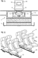
- the Figure 5 shows the groove receiving portion 130 of the mounting rail 100 after the sliding block 200 according to FIGS Figures 2 and 3 inserted into the groove receiving section 130, rotated or swiveled therein and subsequently screwed by means of a screw 310 to a vehicle component 300 located above the mounting rail 100.
- the groove-shaped form-fitting sections 210 and 211 of the sliding block 200 are pulled onto the projections 150 and 151, so that the sliding block 200 is fixed inside the groove-receiving section 130 by positive locking .
- the Figure 6 shows an embodiment for a rail vehicle 10, in which two mounting rails 100, for example the mounting rail 100 according Figure 1, 4th or 5 can be used to assemble vehicle seats 350.
- the vehicle seats 350 thus form vehicle components 300 according to Figure 5 that are attached to the mounting rails 100.
- a mounting method is described below by way of example, in which mounting rails 101 and 102, which correspond to mounting rail 100 according to FIG. 1, are fastened to a body-in-white section 11 of a rail vehicle 10.
- An example is used to explain in detail how a first mounting rail 101 can be connected to a second mounting rail 102 adjacent in the longitudinal direction of the rail.
- the first mounting rail 101 is first attached to the body-in-white section 11 of the rail vehicle 10; the adhesive layer 20, the foam material 30, the metal sheet 50 and the thick-film adhesive 40 are used, the function and arrangement of which is already in connection with the Figure 1 has been explained.
- an end-side interface section 170 of the first mounting rail 101 is preferably left unglued, so that the mounting rail 101 is separated from the body-in-white section 11 by means of an air gap LP.
- an adhesive layer 20 nor a foam material 30, a metal sheet 50 or a thick-layer adhesive 40 such as are used in the central region of the mounting rail 101 for fastening to the body-in-white 11.
- the interface section 170 is provided with four holes 171, which will enable the interface section 170 to be screwed, as will be explained in more detail below.
- the Figure 8 shows the first mounting rail 101 and a connecting plate 500 which has been pushed under the interface section 170 or into the air gap LP between the interface section 170 of the mounting rail 101 and the body-in-white section 11.
- connection plate 500 After the connection plate 500 has been installed, two rod elements 600 and 601 are inserted into the hollow chamber sections 120 and 121 of the mounting rail 101 (cf. Figure 8 ) inserted.
- the rod elements 600 and 601 each have four through holes 610, two of which, after the correct installation of the two rod elements 600 and 601, are each aligned with two holes 171 of the interface section 170 of the first mounting rail 101 (cf. Figure 9 ).
- a second mounting rail 102 which is for example connected to the mounting rail 100 according to FIG. Figure 4 or Figure 5 or can be identical to the first mounting rail 101, with its end-side interface section 170 pushed onto the two rod elements 600 and 601.
- the rod elements 600 and 601 are inserted into the Hollow chamber sections 120 and 121 of the second mounting rail 102 penetrate.
- the interface section 170 of the second mounting rail 102 is - just like that of the first mounting rail 101 - equipped with four holes 171 which, after the correct positioning of the second mounting rail 102 relative to the two rod elements 600 and 601, each have an associated through hole 610 of one of the two rod elements 600 and 601 s worn.
- FIG Figure 10 The two mounting rails 101 and 102 which are aligned relative to one another on the bodyshell 11 in the manner described are shown in FIG Figure 10 shown.
- the Figure 11 shows an example of how the two mounting rails 101 and 102 are screwed to the connecting plate 500 by means of screws 700.
- the connecting plate 500 is provided with threaded holes 501 (cf. Figure 8 ), which are aligned with the through holes 610 located above them in the two rod elements 600 and 601 and the holes 171 in the two interface sections 170 of the two mounting rails 101 and 102.
- the screws 700 are pushed through the holes 171 in the two interface sections 170 and through the through holes 610 in the rod elements 600 and 601 until they can be screwed into the threaded holes 501 in the connecting plate 500.
- the screws 700 are then screwed on, the screws 700 being screwed into the threaded holes 501 of the connecting plate 500, so that the two mounting rails 101 and 102 are screwed tightly to the rod elements 600 and 601 and also to the connecting plate 500.
- pins 750 preferably in the form of dowel pins, are inserted or pressed into corresponding pin holes 502 of the connecting plate 500, so that a further mechanical connection between the connecting plate 500 and the two mounting rails 101 and 102 is manufactured.
- the two interface sections 170 of the two mounting rails 101 and 102 are combined in the exemplary embodiment according to FIGS Figures 7 to 12 , so connected to the connecting plate 500 by a total of eight screws 700 and two pins 750.
- the rod elements 600 and 601 are clamped to the two mounting rails 101 and 102 and the connecting plate 500, which (in particular because of the closed contour of the hollow chamber sections 120 and 121) results in a particularly high mechanical stability of the connection between the two mounting rails 101 and 102 in the transverse direction of the rail is achieved.
- the two pins 750 ensure that particularly large longitudinal forces, which can occur, for example, in the event of temperature fluctuations due to different propagation constants of the material of the body of the rail vehicle 10 and the material of the two mounting rails 101 and 102, are particularly reliably ensured.
- the Figure 13 shows the fully assembled mounting rail 101 in a cross section along the section line XIII-XIII according to FIG. 12.
- the pin 750 can be seen, which establishes a mechanical connection between the connecting plate 500 and the mounting rail 101 lying above it.
- the two rod elements 600 and 601 can be seen, each corresponding to the hollow chamber sections 120 and 121 of the mounting rail 101 and to the hollow chamber sections 120 and 121 of the mounting rail 102 aligned in the longitudinal direction of the rail Figure 12 intervention.
- FIGS 14 and 15 show an embodiment of a connecting plate 500, as used to connect the two mounting rails 101 and 102 according to the Figures 7 to 12 can be used.
- Eight threaded holes 501 can be seen, which are suitable for screwing with the screws 700 Figure 11 or for screwing to the two mounting rails 101 and 102.
- two pin holes 502 can be seen, into which the pins 750 are located Figure 12 for connection to the mounting rail 101 or 102 located above each, insert, in particular, let in.
- the connecting parts of the rail connection are preferably made of steel, stainless steel, light metal, plastic and / or reinforced plastic.
Landscapes
- Engineering & Computer Science (AREA)
- Mechanical Engineering (AREA)
- Life Sciences & Earth Sciences (AREA)
- Wood Science & Technology (AREA)
- Transportation (AREA)
- Connection Of Plates (AREA)
- Fittings On The Vehicle Exterior For Carrying Loads, And Devices For Holding Or Mounting Articles (AREA)
- Seats For Vehicles (AREA)
- Road Signs Or Road Markings (AREA)
- Body Structure For Vehicles (AREA)
Claims (12)
- Véhicule, notamment véhicule (10) ferroviaire, comprenant une barre (100, 101, 102) de montage, dans lequel, à la barre de montage - désignée dans ce qui suit par première barre (101) de montage - est assemblée, notamment vissée et/ou goupillée, une deuxième barre (102) de montage voisine dans la direction longitudinale de la barre,
caractérisé en ce que- chacune des deux barres (100, 101, 102) de montage a, respectivement, une partie (170) d'interface ayant au moins un trou (171), dans lequel une vis (70) passe perpendiculairement à la direction longitudinale de la barre,- dans lequel la vis (700) visse la partie (170) respective d'interface à une plaque (500) de liaison, qui se trouve, par endroit, en dessous de la barre (100, 101, 102) de montage respective et, par endroit, en dessous de la partie (170) d'interface de la barre (100, 101, 102) de montage voisine. - Véhicule suivant la revendication 1,
caractérisé en ce que- les barres (101, 102) de montage sont formées chacune d'un profilé à chambre creuse ou en comprennent un, qui a au moins une partie (170) de chambre creuse à - considéré en section transversale - contour fermé,- considéré dans la direction longitudinale de la barre - au moins un élément (600, 601) de barreau est introduit à la fois dans la partie (170) de chambre creuse de la première barre (101) de montage et dans la partie (170) de chambre creuse de la deuxième barre (102) de montage et- l'élément (600, 601) de barreau, se trouvant dans les parties (170) de chambre creuse, est vissé aux deux barres (101, 102) de montage. - Véhicule suivant la revendication 2,
caractérisé en ce que
l'élément (600, 601) de barreau, se trouvant dans les parties (170) de chambre creuse, est vissé également à la plaque (500) de liaison. - Véhicule suivant l'une des revendications précédentes,
caractérisé en ce que
les deux barres (100, 101, 102) de montage sont goupillées chacune par au moins une goupille (750), de préférence une goupille cylindrique auto-taraudeuse, à la plaque (500) de liaison. - Véhicule suivant l'une des revendications précédentes,
caractérisé en ce que,
sur au moins l'une des barres (100, 101, 102) de montage, un élément du véhicule est monté au moyen d'un coulisseau (200), qui se trouve dans une partie (130) de réception de coulisseau de la barre (100, 101, 102) de montage. - Véhicule suivant la revendication 5,
caractérisé en ce que le coulisseau (200) a au moins une partie (210, 211) à complémentarité de forme, dans laquelle pénètre une partie de la barre (100, 101, 102) de montage. - Véhicule suivant la revendication 6,
caractérisé en ce que- la partie (210, 211) à complémentarité de forme du coulisseau (200) est en forme de goulotte et- la partie de barre, qui y pénètre, de la barre (100, 101, 102) de montage, est formée par une saillie (150, 151) pénétrant dans la partie (130) de réception du coulisseau (200). - Véhicule suivant l'une des revendications 1 à 7,
caractérisé en ce que- un élément du véhicule est monté sur la barre (100, 101, 102) au moyen d'un coulisseau,- dans lequel le coulisseau (200) a au moins une partie (210, 211) à complémentarité de forme, dans laquelle pénètre une partie de la barre (100, 101, 102) de montage. - Véhicule suivant la revendication 8,
caractérisé en ce que
la partie (210, 211) à complémentarité de forme du coulisseau (200) est en forme de goulotte et la partie y pénétrant de la barre (100, 101, 102) de montage est formée par une saillie (150, 151) pénétrant dans l'espace de réception du coulisseau (200). - Procédé de montage d'une barre de montage dans un véhicule, notamment dans un véhicule (10) ferroviaire, dans lequel on monte la barre de montage, désignée dans ce qui suit par première barre (101) de montage, du côté du véhicule et, ensuite, on assemble une deuxième barre (102) de montage-voisine dans la direction longitudinale de la barre - à la première barre (101) de montage, notamment en la vissant et/ou en la goupillant,
caractérisé en ce que- avant, pendant ou après le montage de la première barre (101) de montage, on met une plaque (500) de liaison, par endroit, en dessous de la première barre (101) de montage,- on met la deuxième barre (102) de montage, par endroit, sur une partie, faisant saillie en dessous de la première barre (101) de montage, de la plaque (500) de liaison,- avant, pendant ou après la mise de la deuxième barre (102) de montage, on fait passer, perpendiculairement à la direction longitudinale de la barre, une vis (700) dans un trou (171) d'une partie (170) d'interface de la première barre (101) de montage et on la visse à la plaque (500) de liaison et- on fait passer, perpendiculairement à la direction longitudinale de la barre, une vis (700) dans un trou (171) d'une partie (170) d'interface de la deuxième barre (102) de montage et on la visse à la plaque (500) de liaison. - Procédé suivant l'une des revendications 9 à 10 précédentes,
caractérisé en ce que- les barres (101, 102) de montage sont formées chacune d'un profilé à chambre creuse ayant au moins une partie (170) de chambre creuse ou en comprennent une,- avant, pendant ou après le montage de la première barre (101) de montage - considéré dans la direction longitudinale de la barre - on insère un élément (600, 601) de barreau dans la ou dans l'une des parties (170) de chambre creuse de la première barre (101) de montage,- lors du montage de la deuxième barre (102) de montage, on aligne une partie (170) de chambre creuse de la deuxième barre (102) de montage sur la partie (170) de chambre creuse pourvue de l'élément (600, 601) de barreau de la première barre (101) de montage et on l'enfile sur la partie de barreau, faisant saillie de la première barre (101) de montage, de l'élément (600, 601) de barreau et- on visse l'élément (600, 601) de barreau, se trouvant dans les deux parties (170) de chambre creuse alignées aux deux barres (11, 102) de montage et/ou à la plaque (500) de liaison. - Procédé suivant l'une des revendications 1 à 11 précédentes,
caractérisé en ce que
l'on goupille les deux barres (100, 101, 102) de montage, respectivement, par au moins une goupille (750), de préférence une goupille cylindrique auto-taraudeuse, à la plaque (500) de liaison.
Priority Applications (2)
| Application Number | Priority Date | Filing Date | Title |
|---|---|---|---|
| EP18000334.5A EP3388302B1 (fr) | 2014-07-09 | 2015-07-01 | Véhicule, en particulier véhicule sur rails doté d'un rail de montage |
| PL15733714T PL3140174T3 (pl) | 2014-07-09 | 2015-07-01 | Pojazd, zwłaszcza pojazd szynowy, z szyną montażową |
Applications Claiming Priority (2)
| Application Number | Priority Date | Filing Date | Title |
|---|---|---|---|
| DE102014213365.3A DE102014213365A1 (de) | 2014-07-09 | 2014-07-09 | Fahrzeug, insbesondere Schienenfahrzeug, mit einer Montageschiene |
| PCT/EP2015/064920 WO2016005234A1 (fr) | 2014-07-09 | 2015-07-01 | Véhicule, en particulier véhicule ferroviaire, équipé d'un rail de montage |
Related Child Applications (2)
| Application Number | Title | Priority Date | Filing Date |
|---|---|---|---|
| EP18000334.5A Division EP3388302B1 (fr) | 2014-07-09 | 2015-07-01 | Véhicule, en particulier véhicule sur rails doté d'un rail de montage |
| EP18000334.5A Division-Into EP3388302B1 (fr) | 2014-07-09 | 2015-07-01 | Véhicule, en particulier véhicule sur rails doté d'un rail de montage |
Publications (2)
| Publication Number | Publication Date |
|---|---|
| EP3140174A1 EP3140174A1 (fr) | 2017-03-15 |
| EP3140174B1 true EP3140174B1 (fr) | 2020-03-11 |
Family
ID=53502664
Family Applications (2)
| Application Number | Title | Priority Date | Filing Date |
|---|---|---|---|
| EP18000334.5A Active EP3388302B1 (fr) | 2014-07-09 | 2015-07-01 | Véhicule, en particulier véhicule sur rails doté d'un rail de montage |
| EP15733714.8A Active EP3140174B1 (fr) | 2014-07-09 | 2015-07-01 | Véhicule, en particulier véhicule ferroviaire, équipé d'un rail de montage |
Family Applications Before (1)
| Application Number | Title | Priority Date | Filing Date |
|---|---|---|---|
| EP18000334.5A Active EP3388302B1 (fr) | 2014-07-09 | 2015-07-01 | Véhicule, en particulier véhicule sur rails doté d'un rail de montage |
Country Status (9)
| Country | Link |
|---|---|
| EP (2) | EP3388302B1 (fr) |
| CN (1) | CN207523701U (fr) |
| DE (1) | DE102014213365A1 (fr) |
| DK (1) | DK3140174T3 (fr) |
| ES (2) | ES2874324T3 (fr) |
| PL (1) | PL3140174T3 (fr) |
| PT (1) | PT3140174T (fr) |
| RU (1) | RU179907U1 (fr) |
| WO (1) | WO2016005234A1 (fr) |
Families Citing this family (3)
| Publication number | Priority date | Publication date | Assignee | Title |
|---|---|---|---|---|
| AT516921B1 (de) * | 2015-03-10 | 2017-03-15 | Siemens Ag Oesterreich | Anordnung zur Befestigung eines Koppelelements an einem Wagenkasten eines Fahrzeugs |
| DE102017213552A1 (de) * | 2017-08-04 | 2019-02-07 | Siemens Aktiengesellschaft | Nutenstein, Schienenfahrzeug sowie Verwendung und Herstellungsverfahren eines Nutensteins |
| FR3106556B1 (fr) * | 2020-01-23 | 2022-02-11 | Speedinnov | Motrice ferroviaire avec dispositif de fixation d’équipement technique |
Family Cites Families (11)
| Publication number | Priority date | Publication date | Assignee | Title |
|---|---|---|---|---|
| DE3115699A1 (de) * | 1981-04-18 | 1982-10-28 | Messerschmitt-Bölkow-Blohm GmbH, 8000 München | Ausbildung des fussbodenbereiches von fahrzeugen mit befestigungseinrichtungen |
| DE29500474U1 (de) * | 1995-01-13 | 1995-02-23 | Karmann-Rheine GmbH & Co KG, 48432 Rheine | Vorrichtung zur verschiebbaren Befestigung von Sitzen, Sitzbänken o.ä. Einrichtungsteilen am Karosserieboden von Fahrzeugen zur Personenbeförderung |
| DE29718615U1 (de) * | 1997-10-21 | 1998-03-05 | ProfiTEC, 73432 Aalen | Kanaleinheit |
| DE20106841U1 (de) * | 2001-04-19 | 2001-08-09 | ATECS Mannesmann AG, 40213 Düsseldorf | Schiene für ein Fahrwerk einer Hängebahn |
| DE10159676A1 (de) * | 2001-12-05 | 2003-06-26 | Vogel Ind Gmbh | Bodenverstärkung für Personenbeförderungsfahrzeuge |
| FR2905739B1 (fr) * | 2006-09-08 | 2008-11-07 | Airbus France Sas | Assemblage de panneaux et procede de montage d'un assemblage de panneaux |
| RU76617U1 (ru) * | 2008-03-13 | 2008-09-27 | Открытое Акционерное Общество "Дизельный Завод" | Рама универсального полувагона с люками в полу кузова |
| DE102008048608B4 (de) * | 2008-09-23 | 2014-02-20 | Johannes Wißmann | Bodenkonstruktion für Schienenfahrzeuge |
| DE102008058633A1 (de) * | 2008-11-24 | 2010-05-27 | Siemens Aktiengesellschaft | Fußbodensystem für ein Personentransportfahrzeug, insbesondere Schienenfahrzeug |
| DE102011075825B4 (de) * | 2011-05-13 | 2014-09-18 | Siemens Aktiengesellschaft | Befestigungsvorrichtung für Sitze in Schienenfahrzeugen |
| EP2570322B1 (fr) * | 2011-09-14 | 2014-12-17 | Bombardier Transportation GmbH | Elément de support pour le montage d'un sol de véhicule sur rails, sol d'un wagon de véhicule sur rail et véhicule sur rail |
-
2014
- 2014-07-09 DE DE102014213365.3A patent/DE102014213365A1/de not_active Ceased
-
2015
- 2015-07-01 ES ES18000334T patent/ES2874324T3/es active Active
- 2015-07-01 EP EP18000334.5A patent/EP3388302B1/fr active Active
- 2015-07-01 WO PCT/EP2015/064920 patent/WO2016005234A1/fr not_active Ceased
- 2015-07-01 DK DK15733714.8T patent/DK3140174T3/da active
- 2015-07-01 PL PL15733714T patent/PL3140174T3/pl unknown
- 2015-07-01 RU RU2017103972U patent/RU179907U1/ru active
- 2015-07-01 ES ES15733714T patent/ES2787649T3/es active Active
- 2015-07-01 CN CN201590000801.6U patent/CN207523701U/zh not_active Expired - Lifetime
- 2015-07-01 PT PT157337148T patent/PT3140174T/pt unknown
- 2015-07-01 EP EP15733714.8A patent/EP3140174B1/fr active Active
Non-Patent Citations (1)
| Title |
|---|
| None * |
Also Published As
| Publication number | Publication date |
|---|---|
| EP3388302B1 (fr) | 2021-03-03 |
| ES2874324T3 (es) | 2021-11-04 |
| CN207523701U (zh) | 2018-06-22 |
| PT3140174T (pt) | 2020-04-01 |
| EP3140174A1 (fr) | 2017-03-15 |
| EP3388302A1 (fr) | 2018-10-17 |
| RU179907U1 (ru) | 2018-05-28 |
| ES2787649T3 (es) | 2020-10-16 |
| PL3140174T3 (pl) | 2020-08-10 |
| DE102014213365A1 (de) | 2016-01-14 |
| WO2016005234A1 (fr) | 2016-01-14 |
| DK3140174T3 (da) | 2020-05-18 |
Similar Documents
| Publication | Publication Date | Title |
|---|---|---|
| DE102019101451A1 (de) | Profilanordnung | |
| DE102012022876B4 (de) | Hohlprofil mit einem Verstärkungselement | |
| EP3140174B1 (fr) | Véhicule, en particulier véhicule ferroviaire, équipé d'un rail de montage | |
| DE102013225173A1 (de) | Montageprofil für plattenförmige Module | |
| DE102016124078B3 (de) | Verbindungsanordnung für die Verbindung von zwei Schaltschrankrahmengestellen | |
| DE69400606T2 (de) | Türverstärkung für Kraftfahrzeug | |
| EP2868544B1 (fr) | Dispositif de fixation pour un profilé de transition dans un véhicule sur rail, composant pour un dispositif de fixation et procédé de fixation d'un profilé de transition | |
| DE102016004587A1 (de) | Profilsystem zur Bildung eines Untertragrahmens für die Aufnahme von Bodendielen und Profilschiene | |
| WO2005075253A1 (fr) | Boitier metallique | |
| EP2787265B1 (fr) | Pièce de cornière d'angle | |
| DE202014004275U1 (de) | Befestigungssystem für Inneneinrichtungselemente von Nutzfahrzeugen | |
| EP3934022A1 (fr) | Antenne de toit | |
| EP1798186B1 (fr) | Cabine d'ascenseur et méthode de montage de panneaux d'une parroi de cabine | |
| DE102013205995A1 (de) | Befestigungsanordnung für ein Innenausstattungselement am Wagenkasten eines Fahrzeugs | |
| DE202014103236U1 (de) | Befestigen von Verkleidungsteilen an einer Unterkonstruktion | |
| DE102021115852B4 (de) | Montageanordnung für den Innenausbau eines Schaltschrankgehäuses | |
| DE202014000971U1 (de) | Profilsystem für Verglasungen | |
| DE102013100308A1 (de) | Riegelstangenbeschlag für ein Fenster oder eine Tür | |
| DE102016015791A1 (de) | Verbindungsanordnung für die Verbindung von zwei Schaltschrankrahmengestellen | |
| DE202021102165U1 (de) | System zur Befestigung | |
| DE102015203602A1 (de) | Einstellelement zur Positionierung eines Bauteils | |
| DE102023122136B3 (de) | Adapterbauteil und Verwendung eines Adapterbauteils | |
| DE102011117953A1 (de) | Anordnung eines Außenanbauelements, insbesondere einer Leuchte, an einem Montageträgerelement eines Kraftwagens | |
| EP2966307A1 (fr) | Systeme et procede de fixation de parties de revetement sur une sous-structure | |
| DE102012007233A1 (de) | Befestigungsanordnung eines Energieabsorptionselementes an einem Längsträger eines Kraftwagens |
Legal Events
| Date | Code | Title | Description |
|---|---|---|---|
| STAA | Information on the status of an ep patent application or granted ep patent |
Free format text: STATUS: THE INTERNATIONAL PUBLICATION HAS BEEN MADE |
|
| PUAI | Public reference made under article 153(3) epc to a published international application that has entered the european phase |
Free format text: ORIGINAL CODE: 0009012 |
|
| STAA | Information on the status of an ep patent application or granted ep patent |
Free format text: STATUS: REQUEST FOR EXAMINATION WAS MADE |
|
| 17P | Request for examination filed |
Effective date: 20161206 |
|
| AK | Designated contracting states |
Kind code of ref document: A1 Designated state(s): AL AT BE BG CH CY CZ DE DK EE ES FI FR GB GR HR HU IE IS IT LI LT LU LV MC MK MT NL NO PL PT RO RS SE SI SK SM TR |
|
| AX | Request for extension of the european patent |
Extension state: BA ME |
|
| RAP1 | Party data changed (applicant data changed or rights of an application transferred) |
Owner name: SIEMENS AKTIENGESELLSCHAFT |
|
| DAV | Request for validation of the european patent (deleted) | ||
| DAX | Request for extension of the european patent (deleted) | ||
| RAP1 | Party data changed (applicant data changed or rights of an application transferred) |
Owner name: SIEMENS MOBILITY GMBH |
|
| GRAP | Despatch of communication of intention to grant a patent |
Free format text: ORIGINAL CODE: EPIDOSNIGR1 |
|
| STAA | Information on the status of an ep patent application or granted ep patent |
Free format text: STATUS: GRANT OF PATENT IS INTENDED |
|
| INTG | Intention to grant announced |
Effective date: 20191111 |
|
| RIN1 | Information on inventor provided before grant (corrected) |
Inventor name: SOBOLEWSKI, THOMAS Inventor name: LI, XIAOMENG Inventor name: KIESEL, MICHAEL Inventor name: HESTERBERG, JOSHUA |
|
| GRAS | Grant fee paid |
Free format text: ORIGINAL CODE: EPIDOSNIGR3 |
|
| GRAA | (expected) grant |
Free format text: ORIGINAL CODE: 0009210 |
|
| STAA | Information on the status of an ep patent application or granted ep patent |
Free format text: STATUS: THE PATENT HAS BEEN GRANTED |
|
| AK | Designated contracting states |
Kind code of ref document: B1 Designated state(s): AL AT BE BG CH CY CZ DE DK EE ES FI FR GB GR HR HU IE IS IT LI LT LU LV MC MK MT NL NO PL PT RO RS SE SI SK SM TR |
|
| REG | Reference to a national code |
Ref country code: GB Ref legal event code: FG4D Free format text: NOT ENGLISH |
|
| REG | Reference to a national code |
Ref country code: CH Ref legal event code: EP Ref country code: CH Ref legal event code: NV Representative=s name: VALIPAT S.A. C/O BOVARD SA NEUCHATEL, CH |
|
| REG | Reference to a national code |
Ref country code: AT Ref legal event code: REF Ref document number: 1242785 Country of ref document: AT Kind code of ref document: T Effective date: 20200315 |
|
| REG | Reference to a national code |
Ref country code: IE Ref legal event code: FG4D Free format text: LANGUAGE OF EP DOCUMENT: GERMAN Ref country code: PT Ref legal event code: SC4A Ref document number: 3140174 Country of ref document: PT Date of ref document: 20200401 Kind code of ref document: T Free format text: AVAILABILITY OF NATIONAL TRANSLATION Effective date: 20200324 |
|
| REG | Reference to a national code |
Ref country code: DE Ref legal event code: R096 Ref document number: 502015011986 Country of ref document: DE |
|
| REG | Reference to a national code |
Ref country code: DK Ref legal event code: T3 Effective date: 20200512 |
|
| REG | Reference to a national code |
Ref country code: NL Ref legal event code: FP |
|
| REG | Reference to a national code |
Ref country code: CH Ref legal event code: NV Representative=s name: SIEMENS SCHWEIZ AG, CH |
|
| PG25 | Lapsed in a contracting state [announced via postgrant information from national office to epo] |
Ref country code: RS Free format text: LAPSE BECAUSE OF FAILURE TO SUBMIT A TRANSLATION OF THE DESCRIPTION OR TO PAY THE FEE WITHIN THE PRESCRIBED TIME-LIMIT Effective date: 20200311 Ref country code: FI Free format text: LAPSE BECAUSE OF FAILURE TO SUBMIT A TRANSLATION OF THE DESCRIPTION OR TO PAY THE FEE WITHIN THE PRESCRIBED TIME-LIMIT Effective date: 20200311 Ref country code: NO Free format text: LAPSE BECAUSE OF FAILURE TO SUBMIT A TRANSLATION OF THE DESCRIPTION OR TO PAY THE FEE WITHIN THE PRESCRIBED TIME-LIMIT Effective date: 20200611 |
|
| PG25 | Lapsed in a contracting state [announced via postgrant information from national office to epo] |
Ref country code: SE Free format text: LAPSE BECAUSE OF FAILURE TO SUBMIT A TRANSLATION OF THE DESCRIPTION OR TO PAY THE FEE WITHIN THE PRESCRIBED TIME-LIMIT Effective date: 20200311 Ref country code: BG Free format text: LAPSE BECAUSE OF FAILURE TO SUBMIT A TRANSLATION OF THE DESCRIPTION OR TO PAY THE FEE WITHIN THE PRESCRIBED TIME-LIMIT Effective date: 20200611 Ref country code: HR Free format text: LAPSE BECAUSE OF FAILURE TO SUBMIT A TRANSLATION OF THE DESCRIPTION OR TO PAY THE FEE WITHIN THE PRESCRIBED TIME-LIMIT Effective date: 20200311 Ref country code: GR Free format text: LAPSE BECAUSE OF FAILURE TO SUBMIT A TRANSLATION OF THE DESCRIPTION OR TO PAY THE FEE WITHIN THE PRESCRIBED TIME-LIMIT Effective date: 20200612 Ref country code: LV Free format text: LAPSE BECAUSE OF FAILURE TO SUBMIT A TRANSLATION OF THE DESCRIPTION OR TO PAY THE FEE WITHIN THE PRESCRIBED TIME-LIMIT Effective date: 20200311 |
|
| REG | Reference to a national code |
Ref country code: LT Ref legal event code: MG4D |
|
| REG | Reference to a national code |
Ref country code: ES Ref legal event code: FG2A Ref document number: 2787649 Country of ref document: ES Kind code of ref document: T3 Effective date: 20201016 |
|
| PG25 | Lapsed in a contracting state [announced via postgrant information from national office to epo] |
Ref country code: SK Free format text: LAPSE BECAUSE OF FAILURE TO SUBMIT A TRANSLATION OF THE DESCRIPTION OR TO PAY THE FEE WITHIN THE PRESCRIBED TIME-LIMIT Effective date: 20200311 Ref country code: RO Free format text: LAPSE BECAUSE OF FAILURE TO SUBMIT A TRANSLATION OF THE DESCRIPTION OR TO PAY THE FEE WITHIN THE PRESCRIBED TIME-LIMIT Effective date: 20200311 Ref country code: IS Free format text: LAPSE BECAUSE OF FAILURE TO SUBMIT A TRANSLATION OF THE DESCRIPTION OR TO PAY THE FEE WITHIN THE PRESCRIBED TIME-LIMIT Effective date: 20200711 Ref country code: EE Free format text: LAPSE BECAUSE OF FAILURE TO SUBMIT A TRANSLATION OF THE DESCRIPTION OR TO PAY THE FEE WITHIN THE PRESCRIBED TIME-LIMIT Effective date: 20200311 Ref country code: SM Free format text: LAPSE BECAUSE OF FAILURE TO SUBMIT A TRANSLATION OF THE DESCRIPTION OR TO PAY THE FEE WITHIN THE PRESCRIBED TIME-LIMIT Effective date: 20200311 Ref country code: LT Free format text: LAPSE BECAUSE OF FAILURE TO SUBMIT A TRANSLATION OF THE DESCRIPTION OR TO PAY THE FEE WITHIN THE PRESCRIBED TIME-LIMIT Effective date: 20200311 |
|
| REG | Reference to a national code |
Ref country code: DE Ref legal event code: R097 Ref document number: 502015011986 Country of ref document: DE |
|
| PLBE | No opposition filed within time limit |
Free format text: ORIGINAL CODE: 0009261 |
|
| STAA | Information on the status of an ep patent application or granted ep patent |
Free format text: STATUS: NO OPPOSITION FILED WITHIN TIME LIMIT |
|
| 26N | No opposition filed |
Effective date: 20201214 |
|
| PG25 | Lapsed in a contracting state [announced via postgrant information from national office to epo] |
Ref country code: MC Free format text: LAPSE BECAUSE OF FAILURE TO SUBMIT A TRANSLATION OF THE DESCRIPTION OR TO PAY THE FEE WITHIN THE PRESCRIBED TIME-LIMIT Effective date: 20200311 Ref country code: SI Free format text: LAPSE BECAUSE OF FAILURE TO SUBMIT A TRANSLATION OF THE DESCRIPTION OR TO PAY THE FEE WITHIN THE PRESCRIBED TIME-LIMIT Effective date: 20200311 |
|
| PG25 | Lapsed in a contracting state [announced via postgrant information from national office to epo] |
Ref country code: IE Free format text: LAPSE BECAUSE OF NON-PAYMENT OF DUE FEES Effective date: 20200701 Ref country code: LU Free format text: LAPSE BECAUSE OF NON-PAYMENT OF DUE FEES Effective date: 20200701 |
|
| PG25 | Lapsed in a contracting state [announced via postgrant information from national office to epo] |
Ref country code: MT Free format text: LAPSE BECAUSE OF FAILURE TO SUBMIT A TRANSLATION OF THE DESCRIPTION OR TO PAY THE FEE WITHIN THE PRESCRIBED TIME-LIMIT Effective date: 20200311 Ref country code: CY Free format text: LAPSE BECAUSE OF FAILURE TO SUBMIT A TRANSLATION OF THE DESCRIPTION OR TO PAY THE FEE WITHIN THE PRESCRIBED TIME-LIMIT Effective date: 20200311 |
|
| PG25 | Lapsed in a contracting state [announced via postgrant information from national office to epo] |
Ref country code: MK Free format text: LAPSE BECAUSE OF FAILURE TO SUBMIT A TRANSLATION OF THE DESCRIPTION OR TO PAY THE FEE WITHIN THE PRESCRIBED TIME-LIMIT Effective date: 20200311 Ref country code: AL Free format text: LAPSE BECAUSE OF FAILURE TO SUBMIT A TRANSLATION OF THE DESCRIPTION OR TO PAY THE FEE WITHIN THE PRESCRIBED TIME-LIMIT Effective date: 20200311 |
|
| PGFP | Annual fee paid to national office [announced via postgrant information from national office to epo] |
Ref country code: PT Payment date: 20230620 Year of fee payment: 9 Ref country code: CZ Payment date: 20230623 Year of fee payment: 9 |
|
| PGFP | Annual fee paid to national office [announced via postgrant information from national office to epo] |
Ref country code: TR Payment date: 20230623 Year of fee payment: 9 Ref country code: PL Payment date: 20230623 Year of fee payment: 9 Ref country code: NL Payment date: 20230710 Year of fee payment: 9 |
|
| PGFP | Annual fee paid to national office [announced via postgrant information from national office to epo] |
Ref country code: AT Payment date: 20230609 Year of fee payment: 9 |
|
| PGFP | Annual fee paid to national office [announced via postgrant information from national office to epo] |
Ref country code: DK Payment date: 20230721 Year of fee payment: 9 Ref country code: BE Payment date: 20230719 Year of fee payment: 9 |
|
| PG25 | Lapsed in a contracting state [announced via postgrant information from national office to epo] |
Ref country code: CZ Free format text: LAPSE BECAUSE OF NON-PAYMENT OF DUE FEES Effective date: 20240701 |
|
| PG25 | Lapsed in a contracting state [announced via postgrant information from national office to epo] |
Ref country code: CZ Free format text: LAPSE BECAUSE OF NON-PAYMENT OF DUE FEES Effective date: 20240701 |
|
| REG | Reference to a national code |
Ref country code: DK Ref legal event code: EBP Effective date: 20240731 |
|
| REG | Reference to a national code |
Ref country code: NL Ref legal event code: MM Effective date: 20240801 |
|
| REG | Reference to a national code |
Ref country code: AT Ref legal event code: MM01 Ref document number: 1242785 Country of ref document: AT Kind code of ref document: T Effective date: 20240701 |
|
| PG25 | Lapsed in a contracting state [announced via postgrant information from national office to epo] |
Ref country code: PT Free format text: LAPSE BECAUSE OF NON-PAYMENT OF DUE FEES Effective date: 20250102 |
|
| PG25 | Lapsed in a contracting state [announced via postgrant information from national office to epo] |
Ref country code: NL Free format text: LAPSE BECAUSE OF NON-PAYMENT OF DUE FEES Effective date: 20240801 |
|
| PG25 | Lapsed in a contracting state [announced via postgrant information from national office to epo] |
Ref country code: AT Free format text: LAPSE BECAUSE OF NON-PAYMENT OF DUE FEES Effective date: 20240701 Ref country code: BE Free format text: LAPSE BECAUSE OF NON-PAYMENT OF DUE FEES Effective date: 20240731 |
|
| REG | Reference to a national code |
Ref country code: BE Ref legal event code: MM Effective date: 20240731 |
|
| PG25 | Lapsed in a contracting state [announced via postgrant information from national office to epo] |
Ref country code: DK Free format text: LAPSE BECAUSE OF NON-PAYMENT OF DUE FEES Effective date: 20240731 |
|
| REG | Reference to a national code |
Ref country code: DE Ref legal event code: R081 Ref document number: 502015011986 Country of ref document: DE Owner name: SIEMENS MOBILITY GMBH, DE Free format text: FORMER OWNER: SIEMENS MOBILITY GMBH, 81739 MUENCHEN, DE |
|
| REG | Reference to a national code |
Ref country code: CH Ref legal event code: U11 Free format text: ST27 STATUS EVENT CODE: U-0-0-U10-U11 (AS PROVIDED BY THE NATIONAL OFFICE) Effective date: 20251006 |
|
| PGFP | Annual fee paid to national office [announced via postgrant information from national office to epo] |
Ref country code: DE Payment date: 20250919 Year of fee payment: 11 |
|
| PGFP | Annual fee paid to national office [announced via postgrant information from national office to epo] |
Ref country code: IT Payment date: 20250718 Year of fee payment: 11 |
|
| PGFP | Annual fee paid to national office [announced via postgrant information from national office to epo] |
Ref country code: GB Payment date: 20250811 Year of fee payment: 11 |
|
| PGFP | Annual fee paid to national office [announced via postgrant information from national office to epo] |
Ref country code: FR Payment date: 20250716 Year of fee payment: 11 |
|
| PGFP | Annual fee paid to national office [announced via postgrant information from national office to epo] |
Ref country code: CH Payment date: 20251006 Year of fee payment: 11 |
|
| PG25 | Lapsed in a contracting state [announced via postgrant information from national office to epo] |
Ref country code: PL Free format text: LAPSE BECAUSE OF NON-PAYMENT OF DUE FEES Effective date: 20240701 |
|
| PGFP | Annual fee paid to national office [announced via postgrant information from national office to epo] |
Ref country code: ES Payment date: 20251020 Year of fee payment: 11 |