EP3140178B1 - Frontschott für ein kraftfahrzeug - Google Patents
Frontschott für ein kraftfahrzeug Download PDFInfo
- Publication number
- EP3140178B1 EP3140178B1 EP15723033.5A EP15723033A EP3140178B1 EP 3140178 B1 EP3140178 B1 EP 3140178B1 EP 15723033 A EP15723033 A EP 15723033A EP 3140178 B1 EP3140178 B1 EP 3140178B1
- Authority
- EP
- European Patent Office
- Prior art keywords
- bulkhead
- apron
- vehicle
- tunnel
- structure according
- Prior art date
- Legal status (The legal status is an assumption and is not a legal conclusion. Google has not performed a legal analysis and makes no representation as to the accuracy of the status listed.)
- Not-in-force
Links
Images

Classifications
-
- B—PERFORMING OPERATIONS; TRANSPORTING
- B62—LAND VEHICLES FOR TRAVELLING OTHERWISE THAN ON RAILS
- B62D—MOTOR VEHICLES; TRAILERS
- B62D25/00—Superstructure or monocoque structure sub-units; Parts or details thereof not otherwise provided for
- B62D25/08—Front or rear portions
- B62D25/14—Dashboards as superstructure sub-units
-
- B—PERFORMING OPERATIONS; TRANSPORTING
- B62—LAND VEHICLES FOR TRAVELLING OTHERWISE THAN ON RAILS
- B62D—MOTOR VEHICLES; TRAILERS
- B62D25/00—Superstructure or monocoque structure sub-units; Parts or details thereof not otherwise provided for
- B62D25/20—Floors or bottom sub-units
- B62D25/2009—Floors or bottom sub-units in connection with other superstructure subunits
- B62D25/2045—Floors or bottom sub-units in connection with other superstructure subunits the subunits being fire walls
-
- B—PERFORMING OPERATIONS; TRANSPORTING
- B62—LAND VEHICLES FOR TRAVELLING OTHERWISE THAN ON RAILS
- B62D—MOTOR VEHICLES; TRAILERS
- B62D25/00—Superstructure or monocoque structure sub-units; Parts or details thereof not otherwise provided for
- B62D25/08—Front or rear portions
Definitions
- the invention relates to a front apron for a motor vehicle, the body floor of which is provided with a tunnel.
- the invention relates more particularly to a front apron for a vehicle the engine of which is located at the rear.
- the apron is a generally flat partition with vertical and transverse orientation which must ensure maximum comfort and safety for the passengers of the vehicle.
- the apron provides sound insulation for the passenger compartment.
- Damping elements such as foams are, for example, glued to the apron to absorb a large part of the vibrations and thus reduce the sound level and the vibrations in the passenger compartment.
- the front apron is therefore generally designed so as to avoid direct contact between the front part and the passenger compartment of the vehicle.
- the front apron also has the function of allowing the passage of elements extending both in the passenger compartment and in the front part of the vehicle, such as the steering column, the engine control pedals and the vehicle brakes. .
- front wheels of certain vehicles are not always completely located in front of the front apron.
- a front apron is generally done by stamping.
- a rectangular sheet metal side is stamped so as to make the openings, the recesses and the cutout. Stamping also makes it possible to adapt the shape of the apron to the architecture of the motor vehicle.
- the rectangular sheet sidewall is of course of greater mass than that of the finished part. Part of the sidewall constitutes the finished part, while the rest constitutes the offcuts, i.e. unused material.
- the material engagement represents the ratio between the mass of the finished part and the mass of the sidewall used.
- the material engagement represents the ratio between the mass of the finished part and the mass of the sidewall used.
- the aim of the invention is to provide an apron designed so as to be able to be produced by stamping with a significant material engagement, and suitable for a vehicle provided with an engine at the rear.
- a motor vehicle structure comprising a front apron and a body floor provided with a tunnel, the apron comprising a lower edge, an upper edge and two lateral sides.
- the lower and upper edges are continuous and substantially parallel, the lower edge being devoid of a cutout at the junction with the vehicle body floor tunnel, the lateral sides having solid portions integrating the shape of the wheel arches.
- Such a one-piece apron is designed so as to use the raw material in an optimized manner.
- such a part can be produced by stamping with a material engagement greater than 69%.
- a better material commitment has advantages in terms of the cost of manufacturing the part.
- the deck has a more resistant structure and presents a lower risk of corrosion.
- the front apron comprises a first substantially vertical surface and disposed towards the front and a second adjacent surface inclined towards the rear when the apron is mounted in the vehicle, the second surface having in its central part a recess. forming a closed hollow body adapted to house the front end of the tunnel of a vehicle body floor.
- the apron is produced by stamping from a sheet metal side.
- the first surface is suitable for mounting the pedals and the steering column.
- the apron comprises a cutout made in the first surface provided for mounting a separate reinforcement.
- the first surface has a blind cavity in which four threaded holes are made.
- a motor vehicle comprises a body floor provided with a tunnel extending in the direction longitudinal vehicle and a front apron as defined above.
- a mastic seal is disposed along the lower and upper edges and the lateral sides of the front apron.
- FIG. 1 a schematic perspective view of a front apron 1 according to a first embodiment.
- the front apron 1 consists of a single piece of deformed sheet metal, for example produced by stamping from a flat sheet.
- the front apron 1 therefore comprises a first substantially planar surface 2 with local deformations.
- the first surface 2 is substantially vertical and disposed towards the front when the apron 1 is mounted in the vehicle.
- the apron 1 comprises a second surface 3 adjacent and inclined with respect to the first surface 2 towards the rear when the apron 1 is mounted in the vehicle.
- An upper rim 4 is adjacent to the second surface 2.
- the front apron 1 comprises an upper edge 5a, belonging to the flange 4 and a lower edge 5b, belonging to the second surface 3.
- the upper 5a and lower 5b edges are continuous and substantially parallel to one another.
- the apron 1 has an overall rectangular shape.
- the front apron 1 is intended to be incorporated into the structure of a motor vehicle generally composed of a body floor, a bonnet support, a front cross member and two side body cheeks.
- the upper edge 5a is intended to be held against the cover support (not shown).
- the lower edge 5b is intended to be in contact with the body floor 12 (shown in figure 2 ).
- the left and right sides 6a and 6b are respectively intended to be placed in contact with the left and right side bodywork cheeks (not shown).
- Three identical holes 7 are made on the first surface 2, in order to allow the fixing of the surface 2 to the cross member of the vehicle (not shown), by means of bolts not shown. It is also possible to make welds at the edges 5a and 5b and at the sides 6a and 6b.
- edges 5a and 5b, sides 6a and 6b and holes 7, the front apron 1 is designed to be incorporated into the structure of the vehicle.
- the body floor 12 of the vehicle is provided with a tunnel 13, generally extending over the entire length of the vehicle.
- the body floor tunnel 13 12 is therefore generally placed in contact with or crossing the front apron 1 of the vehicle, defining a junction zone of the apron with the tunnel.
- the engine being at the rear, it is not necessary for the tunnel 13 to cross the apron 1.
- the junction zone is part of the second surface 3 which has a recess forming a closed hollow body 8 arranged on the central part of the second surface 3, and intended to house the front end of the tunnel 13 of the body floor 12 of the vehicle.
- the recess 8 is preferably delimited by a surface portion 8a of greater inclination than that of the second surface 3 in order to receive the tapered end of the tunnel 13.
- the front apron 1 also comprises a cutout 9 arranged on the first surface 2.
- the cutout 9 is provided for mounting a separate reinforcement (visible in figure 2 ) incorporating for example means for passing through the steering column and the vehicle control pedals.
- the front apron 1 comprises on its left side 6a (compared to the figure 1 ) a solid portion integrating a left wheel arch 10a comprising a junction surface 11a of substantially conical or curved shape. These local deformations of the solid portion are easily achievable by stamping.
- the front apron 1 furthermore comprises on its right side 6b, symmetrically, a right wheel arch 10b comprising a junction surface 11b which is substantially conical or curved.
- the front apron 1 arranged on the body floor 12 of the motor vehicle.
- the motor of the motor vehicle is located at the rear thereof.
- the body floor 12 is a flat surface on which the tunnel 13 is mounted, and in which there are wheel openings 14a and 14b (only the left wheel opening 14a being visible on the figure 2 ).
- Fastening means (not shown) make it possible to make the body floor 12 integral with the front apron 1, at the level of the lower edge 5b of the latter.
- the tunnel 13 does not pass through the front apron 1 and comes into abutment against the hollow body 8, which reinforces the assembly of the floor 12 with the apron 1.
- the front apron 1 comprises a reinforcement 15 mounted in the opening 9.
- the reinforcement 15 comprises a cavity 16 and a hole 17 provided for mounting the steering column of the vehicle (not shown).
- Four identical threaded holes 18 are provided for fixing the steering column of the vehicle to the reinforcement 15 of the front apron 1, at the level of the cavity 16.
- the reinforcement 15 finally comprises three holes 19 provided for the cables of the vehicle control pedals. , for example the cables of the accelerator pedal, the brake pedal and the clutch pedal.
- the perforation 9 is located in the central left part of the apron 1 to enable the driver's station to be fitted on the left side of the vehicle.
- the front apron 1 is a part of generally rectangular shape with local deformations. It can be produced by stamping from a rectangular sheet sidewall. The absence of a cutout for the tunnel and the integration of the wheel arches in a solid portion improve the material engagement. It is estimated that such a form of front apron makes it possible to achieve a material engagement greater than 69%, much greater than the average material engagement of a front apron, estimated at around 55%.
- the apron has substantially a mass of 5.73kg.
- the sheet metal side used has a mass of 8.23 kg, ie a material commitment of 69.5%.
- Such an architecture therefore makes it possible to reduce the cost of manufacturing the apron, to improve its structure and its resistance to corrosion.
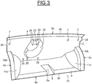
- the apron 21 differs from the apron 1 of the figure 1 by the absence of the perforation 9 in the central left part of the surface 2.
- the central left part is itself adapted to the mounting of the steering column and of the vehicle control pedals.
- a blind cavity 22 is made in the surface 2, comprising a hole 23 and four identical threaded holes 24. These elements respectively have the same function as the cavity 16, the hole 17 and the threaded holes 18 of the reinforcement 15 of the figure 2 .
- the apron 21 finally comprises on its surface 2 three holes 25, the function of which is the same as that of the three holes 19 of the reinforcement 15.
- FIG 3 there is also shown a mastic seal 26 disposed over the entire outer periphery of the front apron 21, to know on sides 5a, 5b, 6a and 6b.
- a similar seal can be provided around the front apron 1 of the figures 1 and 2 .
- the apron can be produced by stamping from a rectangular sheet sidewall.
- the absence of a cutout for the tunnel and the integration of the wheel arches in a solid portion make it possible to reduce the manufacturing cost of the apron and to improve its structure and its resistance to corrosion.
Landscapes
- Engineering & Computer Science (AREA)
- Chemical & Material Sciences (AREA)
- Combustion & Propulsion (AREA)
- Transportation (AREA)
- Mechanical Engineering (AREA)
- Body Structure For Vehicles (AREA)
Claims (7)
- Kraftfahrzeugstruktur, umfassend eine Frontschürze (1, 21) und einen Karosserieboden (12), der mit einem Tunnel (13) versehen ist, wobei die Schürze (1, 21) eine untere Kante (5b), eine obere Kante (5a) und zwei Seitenkanten (6a, 6b) umfasst, die massive Abschnitte aufweisen, die die Form der Radkästen (10a, 10b) integrieren, wobei die untere (5b) und die obere Kante (5a) durchgehend und im Wesentlichen parallel sind, dadurch gekennzeichnet, dass der Tunnel (13) des Karosseriebodens (12) in nicht durchgehendem Kontakt mit der Schürze (1, 21) und ohne Ausschnitt derselben angeordnet ist und mit dieser einen Verbindungsbereich (8) definiert, der Teil einer zweiten geneigten Fläche (3) der Schürze (1, 21) ist und hinter einer im Wesentlichen vertikalen ersten Fläche (2) der Schürze (1) angeordnet ist, wenn die Schürze (1, 21) im Fahrzeug montiert ist, wobei die zweite Fläche (3) in ihrem mittleren Teil eine Aussparung aufweist, die einen geschlossenen Hohlkörper bildet, der zur Aufnahme des vorderen Endes des Tunnels (13) geeignet ist, wobei die Schürze durch Tiefziehen aus einem Blechstück gefertigt.
- Struktur nach Anspruch 1, dadurch gekennzeichnet, dass die massiven Abschnitte, die die Form der Radkästen (10a, 10b) integrieren, eine im Wesentlichen konische und gekrümmte Verbindungsfläche (11a, 11b) umfassen.
- Struktur nach Anspruch 2, dadurch gekennzeichnet, dass die erste Fläche (2) zur Montage der Pedale und der Lenksäule geeignet ist.
- Struktur nach einem der Ansprüche 1 bis 3, dadurch gekennzeichnet, dass sie eine Aussparung (9) umfasst, die in der ersten Fläche (2) ausgeführt und zur Montage einer separaten Verstärkung (15) vorgesehen ist.
- Struktur nach einem der Ansprüche 1 bis 3, dadurch gekennzeichnet, dass die erste Fläche (2) einen Blindhohlraum (22) aufweist, in dem vier Gewindelöcher (24) ausgeführt sind.
- Kraftfahrzeug, umfassend eine Struktur nach einem der Ansprüche 1 bis 5.
- Fahrzeug nach Anspruch 6, dadurch gekennzeichnet, dass entlang der unteren (5b) und der oberen Kante (5a) sowie der Seitenkanten (6a, 6b) der Frontschürze (1, 21) eine Spachtelverbindung (26) angeordnet ist.
Applications Claiming Priority (2)
| Application Number | Priority Date | Filing Date | Title |
|---|---|---|---|
| FR1454105A FR3020793B1 (fr) | 2014-05-07 | 2014-05-07 | Tablier avant pour vehicule automobile. |
| PCT/FR2015/051056 WO2015170024A1 (fr) | 2014-05-07 | 2015-04-17 | Tablier avant pour vehicule automobile |
Publications (2)
| Publication Number | Publication Date |
|---|---|
| EP3140178A1 EP3140178A1 (de) | 2017-03-15 |
| EP3140178B1 true EP3140178B1 (de) | 2021-10-20 |
Family
ID=51063695
Family Applications (1)
| Application Number | Title | Priority Date | Filing Date |
|---|---|---|---|
| EP15723033.5A Not-in-force EP3140178B1 (de) | 2014-05-07 | 2015-04-17 | Frontschott für ein kraftfahrzeug |
Country Status (5)
| Country | Link |
|---|---|
| US (1) | US10272953B2 (de) |
| EP (1) | EP3140178B1 (de) |
| CN (1) | CN106794877B (de) |
| FR (1) | FR3020793B1 (de) |
| WO (1) | WO2015170024A1 (de) |
Families Citing this family (3)
| Publication number | Priority date | Publication date | Assignee | Title |
|---|---|---|---|---|
| JP7095476B2 (ja) * | 2018-08-07 | 2022-07-05 | トヨタ自動車株式会社 | 車両前部構造 |
| US10940893B2 (en) * | 2019-07-17 | 2021-03-09 | GM Global Technology Operations LLC | Reinforced open-section structural panel |
| EP4091916B1 (de) * | 2021-05-19 | 2025-11-05 | GF Casting Solutions AG | Strukturbauteil |
Citations (1)
| Publication number | Priority date | Publication date | Assignee | Title |
|---|---|---|---|---|
| WO2013088896A1 (ja) * | 2011-12-15 | 2013-06-20 | 本田技研工業株式会社 | 車体構造 |
Family Cites Families (37)
| Publication number | Priority date | Publication date | Assignee | Title |
|---|---|---|---|---|
| BE511731A (de) * | 1951-08-25 | |||
| US4514008A (en) * | 1981-06-05 | 1985-04-30 | Toyota Jidosha Kogyo Kabushiki Kaisha | Vehicle body floor construction of motor vehicle |
| US4457555A (en) * | 1981-07-10 | 1984-07-03 | Cars & Concepts, Inc. | Conversion of vehicle bodies |
| DE3223156A1 (de) * | 1982-06-22 | 1983-12-22 | Dr.Ing.H.C. F. Porsche Ag, 7000 Stuttgart | Aufbau fuer kraftfahrzeuge, insbesondere personenkraftwagen |
| DE3346260A1 (de) * | 1983-12-21 | 1985-07-11 | Dr. Alois Stankiewicz GmbH, 3101 Adelheidsdorf | Vorrichtung zur schallfeldstoerung |
| KR910000502B1 (ko) * | 1986-09-26 | 1991-01-26 | 마쯔다 가부시끼가이샤 | 자동차의 앞부분 차체구조 |
| IT1224026B (it) * | 1988-12-23 | 1990-09-26 | Fiat Auto Spa | Struttura di veicolo e metodo per il suo assemblaggio |
| FR2676688B1 (fr) * | 1991-05-24 | 1993-10-08 | Ecia Equip Composants Ind Auto | Planche de bord perfectionnee. |
| JP3179187B2 (ja) * | 1992-06-09 | 2001-06-25 | マツダ株式会社 | 自動車の車体構造 |
| DE19819446A1 (de) * | 1998-04-30 | 1999-11-04 | Volkswagen Ag | Karosseriestruktur eines Kraftfahrzeuges |
| US6237439B1 (en) * | 1999-09-09 | 2001-05-29 | Visteon Global Technologies, Inc. | Single release lever for steering column tilt and telescope |
| US6460918B1 (en) * | 1999-10-19 | 2002-10-08 | Nissan Motor Co., Ltd. | Vehicle body structure |
| KR100320836B1 (ko) * | 1999-12-29 | 2002-01-18 | 이계안 | 화물 자동차용 캡의 비틀림 방지 구조 |
| FR2803813B1 (fr) | 2000-01-14 | 2002-03-08 | Renault | Tablier avant de vehicule automobile |
| US6769733B2 (en) * | 2001-10-16 | 2004-08-03 | Alcoa Inc. | Bulkhead assembly for a motor vehicle |
| US6755461B2 (en) * | 2001-10-16 | 2004-06-29 | Aloca Inc. | Modular front end for a motor vehicle |
| DE10218926A1 (de) * | 2002-04-27 | 2003-12-04 | Daimler Chrysler Ag | Bodengruppe für ein Fahrerhaus |
| US6974172B2 (en) * | 2002-09-27 | 2005-12-13 | Collins & Aikman Products Co. | Vehicle cockpit assemblies having integrated dash insulators, instrument panels and floor coverings, and methods of installing same within vehicles |
| JP4346313B2 (ja) * | 2003-01-08 | 2009-10-21 | 富士重工業株式会社 | 自動車の車体前部構造 |
| JP4144385B2 (ja) * | 2003-03-12 | 2008-09-03 | 三菱自動車工業株式会社 | 自動車の車室前部の結合構造 |
| JP4005549B2 (ja) * | 2003-10-08 | 2007-11-07 | 本田技研工業株式会社 | テーラードブランクからなる自動車のダッシュボードの開口部構造 |
| JP4872586B2 (ja) * | 2005-11-10 | 2012-02-08 | 日産自動車株式会社 | 車体前部構造および連結部材 |
| JP4304529B2 (ja) * | 2006-08-04 | 2009-07-29 | トヨタ自動車株式会社 | 車両の下部構造 |
| JP4825640B2 (ja) | 2006-11-10 | 2011-11-30 | 本田技研工業株式会社 | 自動車の車体構造 |
| DE102008049763A1 (de) * | 2008-09-30 | 2010-04-01 | GM Global Technology Operations, Inc., Detroit | Karosserie für ein Kraftfahrzeug |
| DE102010018481A1 (de) * | 2010-04-28 | 2011-11-03 | Gm Global Technology Operations Llc (N.D.Ges.D. Staates Delaware) | Bodenstruktur einer Kraftfahrzeugkarosserie |
| JP5495119B2 (ja) * | 2010-05-07 | 2014-05-21 | スズキ株式会社 | 車体前部の補強構造 |
| JP5670246B2 (ja) * | 2011-04-07 | 2015-02-18 | 本田技研工業株式会社 | 車体下部構造 |
| US8925991B2 (en) * | 2011-06-08 | 2015-01-06 | Ford Global Technologies, Llc | Reinforced frame-to-body attachment |
| JP5651780B2 (ja) * | 2011-07-30 | 2015-01-14 | 本田技研工業株式会社 | 車体前部構造 |
| DE102011121908A1 (de) * | 2011-12-22 | 2013-06-27 | Gm Global Technology Operations, Llc | Kraftfahrzeugkarosserie mit Verstärkungsstruktur |
| JP5560298B2 (ja) * | 2012-04-05 | 2014-07-23 | 本田技研工業株式会社 | 車体前部構造 |
| CN203222035U (zh) * | 2013-04-16 | 2013-10-02 | 比亚迪股份有限公司 | 混合动力汽车及其前舱 |
| JP5924331B2 (ja) * | 2013-11-25 | 2016-05-25 | トヨタ自動車株式会社 | 車体下部構造 |
| US9266567B1 (en) * | 2014-10-21 | 2016-02-23 | Toyota Motor Engineering & Manufacturing North America, Inc. | Vehicles having a dash panel reinforcement gusset |
| EP3100935B1 (de) * | 2015-06-04 | 2019-05-01 | FCA Italy S.p.A. | Kraftfahrzeugbodenplattenstruktur |
| JP2017024698A (ja) * | 2015-07-15 | 2017-02-02 | 現代自動車株式会社Hyundai Motor Company | 車体結合構造 |
-
2014
- 2014-05-07 FR FR1454105A patent/FR3020793B1/fr not_active Expired - Fee Related
-
2015
- 2015-04-17 CN CN201580030334.6A patent/CN106794877B/zh not_active Expired - Fee Related
- 2015-04-17 WO PCT/FR2015/051056 patent/WO2015170024A1/fr not_active Ceased
- 2015-04-17 EP EP15723033.5A patent/EP3140178B1/de not_active Not-in-force
- 2015-04-17 US US15/330,792 patent/US10272953B2/en not_active Expired - Fee Related
Patent Citations (2)
| Publication number | Priority date | Publication date | Assignee | Title |
|---|---|---|---|---|
| WO2013088896A1 (ja) * | 2011-12-15 | 2013-06-20 | 本田技研工業株式会社 | 車体構造 |
| EP2792526A1 (de) * | 2011-12-15 | 2014-10-22 | Honda Motor Co., Ltd. | Fahrzeugaufbaustruktur |
Also Published As
| Publication number | Publication date |
|---|---|
| US10272953B2 (en) | 2019-04-30 |
| EP3140178A1 (de) | 2017-03-15 |
| US20170274938A1 (en) | 2017-09-28 |
| CN106794877B (zh) | 2020-04-03 |
| WO2015170024A1 (fr) | 2015-11-12 |
| FR3020793A1 (fr) | 2015-11-13 |
| CN106794877A (zh) | 2017-05-31 |
| FR3020793B1 (fr) | 2016-10-21 |
Similar Documents
| Publication | Publication Date | Title |
|---|---|---|
| EP2678194B1 (de) | Halterung für einen sicherheitsgurtaufroller | |
| EP3140178B1 (de) | Frontschott für ein kraftfahrzeug | |
| EP3724039B1 (de) | Trennwand für ein kraftfahrzeug | |
| EP2080689A2 (de) | Vorrichtung zur seitlichen Verstärkung des Vorderbaus eines Kraftfahrzeugs und mit einer solchen Vorrichtung ausgestattetes Kraftfahrzeug | |
| EP3083375B1 (de) | Anordnung mit einem armaturenbrett-querträger für ein motorfahrzeug und doppelseitige träger zur sicherung des querträgers an der fahrzeugkarosserie | |
| EP1580098B1 (de) | Dach für Kraftfahrzeug, und Kraftfahrzeug mit einem derartigen Dach | |
| FR2922179A1 (fr) | Structure de caisse de vehicule automobile et vehicule comportant une telle structure de caisse. | |
| EP2867097B1 (de) | Kraftfahrzeug mit einem zusatzbewehrungsteil zur anleitung der verformung der zentralen säulenstruktur bei einem seitenaufprall | |
| FR3099907A1 (fr) | Déflecteur aérodynamique arrière pour véhicule automobile | |
| FR2924674A1 (fr) | Structure de caisse de vehicule automobile | |
| EP2088060B1 (de) | Schmutzfänger eines Kraftfahrzeugs mit einer Akustikblende | |
| EP3097000B1 (de) | Karosserieaufbau eines kraftfahrzeugs mit verstärkungen zur verteilung der kräfte in verbindung mit einem hinteren stossdämpfer des fahrzeugs | |
| EP2173604B1 (de) | Anordnung zur befestigung zweier benachbarter karosserie-elemente | |
| EP3898388B1 (de) | Verstärkungsteil zur ausstattung eines kraftfahrzeugs gegen einen frontalaufprall | |
| FR3139786A1 (fr) | extension de longeronnet pour véhicule automobile | |
| FR2926279A1 (fr) | Dispositif de renfort lateral pour bloc avant de vehicule automobile et vehicule automobile equipe d'un tel dispositif | |
| EP4359284B1 (de) | Kraftfahrzeuginnenverkleidungselement | |
| EP4031416B1 (de) | Kraftfahrzeugverkleidungsteil aus expandiertem polymermaterial | |
| EP2183149B1 (de) | Auskleidung für den heckspoiler eines motorfahrzeugs sowie motorfahrzeug mit mindestens einer solchen auskleidung | |
| EP3536585B1 (de) | Blechpaneel, das eine verkleidung des hinteren teils der seitenfläche eines fahrzeugaufbaus und einen hinteren radkasten darstellt | |
| EP1806273B1 (de) | Bodenalage eines Kraftfahrzeuges | |
| EP2042367B1 (de) | Vorrichtung zur Versteifung eines Kraftfahrzeugbodens zum Befestigen eines Rücksitzes | |
| FR3160376A1 (fr) | Longeron de véhicule automobile renforcé et ensemble de soubassement comportant un tel longeron | |
| EP3164321B1 (de) | Verbindungsstruktur zur verbindung zwischen einer vorderen struktur der karosserie eines kraftfahrzeugs und der unterkonstruktion dieses kraftfahrzeugs | |
| WO2023227838A1 (fr) | Structure de caisse de véhicule automobile à déformation contrôlée de l'arc pavillon en cas de choc frontal |
Legal Events
| Date | Code | Title | Description |
|---|---|---|---|
| STAA | Information on the status of an ep patent application or granted ep patent |
Free format text: STATUS: THE INTERNATIONAL PUBLICATION HAS BEEN MADE |
|
| PUAI | Public reference made under article 153(3) epc to a published international application that has entered the european phase |
Free format text: ORIGINAL CODE: 0009012 |
|
| STAA | Information on the status of an ep patent application or granted ep patent |
Free format text: STATUS: REQUEST FOR EXAMINATION WAS MADE |
|
| 17P | Request for examination filed |
Effective date: 20161206 |
|
| AK | Designated contracting states |
Kind code of ref document: A1 Designated state(s): AL AT BE BG CH CY CZ DE DK EE ES FI FR GB GR HR HU IE IS IT LI LT LU LV MC MK MT NL NO PL PT RO RS SE SI SK SM TR |
|
| AX | Request for extension of the european patent |
Extension state: BA ME |
|
| DAV | Request for validation of the european patent (deleted) | ||
| DAX | Request for extension of the european patent (deleted) | ||
| STAA | Information on the status of an ep patent application or granted ep patent |
Free format text: STATUS: EXAMINATION IS IN PROGRESS |
|
| 17Q | First examination report despatched |
Effective date: 20200408 |
|
| GRAP | Despatch of communication of intention to grant a patent |
Free format text: ORIGINAL CODE: EPIDOSNIGR1 |
|
| STAA | Information on the status of an ep patent application or granted ep patent |
Free format text: STATUS: GRANT OF PATENT IS INTENDED |
|
| INTG | Intention to grant announced |
Effective date: 20210517 |
|
| GRAS | Grant fee paid |
Free format text: ORIGINAL CODE: EPIDOSNIGR3 |
|
| GRAA | (expected) grant |
Free format text: ORIGINAL CODE: 0009210 |
|
| STAA | Information on the status of an ep patent application or granted ep patent |
Free format text: STATUS: THE PATENT HAS BEEN GRANTED |
|
| AK | Designated contracting states |
Kind code of ref document: B1 Designated state(s): AL AT BE BG CH CY CZ DE DK EE ES FI FR GB GR HR HU IE IS IT LI LT LU LV MC MK MT NL NO PL PT RO RS SE SI SK SM TR |
|
| REG | Reference to a national code |
Ref country code: GB Ref legal event code: FG4D Free format text: NOT ENGLISH |
|
| REG | Reference to a national code |
Ref country code: CH Ref legal event code: EP |
|
| REG | Reference to a national code |
Ref country code: DE Ref legal event code: R096 Ref document number: 602015074243 Country of ref document: DE |
|
| REG | Reference to a national code |
Ref country code: IE Ref legal event code: FG4D Free format text: LANGUAGE OF EP DOCUMENT: FRENCH |
|
| REG | Reference to a national code |
Ref country code: AT Ref legal event code: REF Ref document number: 1439718 Country of ref document: AT Kind code of ref document: T Effective date: 20211115 |
|
| REG | Reference to a national code |
Ref country code: LT Ref legal event code: MG9D |
|
| REG | Reference to a national code |
Ref country code: NL Ref legal event code: MP Effective date: 20211020 |
|
| RAP4 | Party data changed (patent owner data changed or rights of a patent transferred) |
Owner name: RENAULT S.A.S |
|
| REG | Reference to a national code |
Ref country code: AT Ref legal event code: MK05 Ref document number: 1439718 Country of ref document: AT Kind code of ref document: T Effective date: 20211020 |
|
| PG25 | Lapsed in a contracting state [announced via postgrant information from national office to epo] |
Ref country code: RS Free format text: LAPSE BECAUSE OF FAILURE TO SUBMIT A TRANSLATION OF THE DESCRIPTION OR TO PAY THE FEE WITHIN THE PRESCRIBED TIME-LIMIT Effective date: 20211020 Ref country code: LT Free format text: LAPSE BECAUSE OF FAILURE TO SUBMIT A TRANSLATION OF THE DESCRIPTION OR TO PAY THE FEE WITHIN THE PRESCRIBED TIME-LIMIT Effective date: 20211020 Ref country code: FI Free format text: LAPSE BECAUSE OF FAILURE TO SUBMIT A TRANSLATION OF THE DESCRIPTION OR TO PAY THE FEE WITHIN THE PRESCRIBED TIME-LIMIT Effective date: 20211020 Ref country code: BG Free format text: LAPSE BECAUSE OF FAILURE TO SUBMIT A TRANSLATION OF THE DESCRIPTION OR TO PAY THE FEE WITHIN THE PRESCRIBED TIME-LIMIT Effective date: 20220120 Ref country code: AT Free format text: LAPSE BECAUSE OF FAILURE TO SUBMIT A TRANSLATION OF THE DESCRIPTION OR TO PAY THE FEE WITHIN THE PRESCRIBED TIME-LIMIT Effective date: 20211020 |
|
| PG25 | Lapsed in a contracting state [announced via postgrant information from national office to epo] |
Ref country code: IS Free format text: LAPSE BECAUSE OF FAILURE TO SUBMIT A TRANSLATION OF THE DESCRIPTION OR TO PAY THE FEE WITHIN THE PRESCRIBED TIME-LIMIT Effective date: 20220220 Ref country code: SE Free format text: LAPSE BECAUSE OF FAILURE TO SUBMIT A TRANSLATION OF THE DESCRIPTION OR TO PAY THE FEE WITHIN THE PRESCRIBED TIME-LIMIT Effective date: 20211020 Ref country code: PT Free format text: LAPSE BECAUSE OF FAILURE TO SUBMIT A TRANSLATION OF THE DESCRIPTION OR TO PAY THE FEE WITHIN THE PRESCRIBED TIME-LIMIT Effective date: 20220221 Ref country code: PL Free format text: LAPSE BECAUSE OF FAILURE TO SUBMIT A TRANSLATION OF THE DESCRIPTION OR TO PAY THE FEE WITHIN THE PRESCRIBED TIME-LIMIT Effective date: 20211020 Ref country code: NO Free format text: LAPSE BECAUSE OF FAILURE TO SUBMIT A TRANSLATION OF THE DESCRIPTION OR TO PAY THE FEE WITHIN THE PRESCRIBED TIME-LIMIT Effective date: 20220120 Ref country code: NL Free format text: LAPSE BECAUSE OF FAILURE TO SUBMIT A TRANSLATION OF THE DESCRIPTION OR TO PAY THE FEE WITHIN THE PRESCRIBED TIME-LIMIT Effective date: 20211020 Ref country code: LV Free format text: LAPSE BECAUSE OF FAILURE TO SUBMIT A TRANSLATION OF THE DESCRIPTION OR TO PAY THE FEE WITHIN THE PRESCRIBED TIME-LIMIT Effective date: 20211020 Ref country code: HR Free format text: LAPSE BECAUSE OF FAILURE TO SUBMIT A TRANSLATION OF THE DESCRIPTION OR TO PAY THE FEE WITHIN THE PRESCRIBED TIME-LIMIT Effective date: 20211020 Ref country code: GR Free format text: LAPSE BECAUSE OF FAILURE TO SUBMIT A TRANSLATION OF THE DESCRIPTION OR TO PAY THE FEE WITHIN THE PRESCRIBED TIME-LIMIT Effective date: 20220121 Ref country code: ES Free format text: LAPSE BECAUSE OF FAILURE TO SUBMIT A TRANSLATION OF THE DESCRIPTION OR TO PAY THE FEE WITHIN THE PRESCRIBED TIME-LIMIT Effective date: 20211020 |
|
| REG | Reference to a national code |
Ref country code: DE Ref legal event code: R097 Ref document number: 602015074243 Country of ref document: DE |
|
| RAP4 | Party data changed (patent owner data changed or rights of a patent transferred) |
Owner name: RENAULT S.A.S |
|
| PG25 | Lapsed in a contracting state [announced via postgrant information from national office to epo] |
Ref country code: SM Free format text: LAPSE BECAUSE OF FAILURE TO SUBMIT A TRANSLATION OF THE DESCRIPTION OR TO PAY THE FEE WITHIN THE PRESCRIBED TIME-LIMIT Effective date: 20211020 Ref country code: SK Free format text: LAPSE BECAUSE OF FAILURE TO SUBMIT A TRANSLATION OF THE DESCRIPTION OR TO PAY THE FEE WITHIN THE PRESCRIBED TIME-LIMIT Effective date: 20211020 Ref country code: RO Free format text: LAPSE BECAUSE OF FAILURE TO SUBMIT A TRANSLATION OF THE DESCRIPTION OR TO PAY THE FEE WITHIN THE PRESCRIBED TIME-LIMIT Effective date: 20211020 Ref country code: EE Free format text: LAPSE BECAUSE OF FAILURE TO SUBMIT A TRANSLATION OF THE DESCRIPTION OR TO PAY THE FEE WITHIN THE PRESCRIBED TIME-LIMIT Effective date: 20211020 Ref country code: DK Free format text: LAPSE BECAUSE OF FAILURE TO SUBMIT A TRANSLATION OF THE DESCRIPTION OR TO PAY THE FEE WITHIN THE PRESCRIBED TIME-LIMIT Effective date: 20211020 Ref country code: CZ Free format text: LAPSE BECAUSE OF FAILURE TO SUBMIT A TRANSLATION OF THE DESCRIPTION OR TO PAY THE FEE WITHIN THE PRESCRIBED TIME-LIMIT Effective date: 20211020 |
|
| PLBE | No opposition filed within time limit |
Free format text: ORIGINAL CODE: 0009261 |
|
| STAA | Information on the status of an ep patent application or granted ep patent |
Free format text: STATUS: NO OPPOSITION FILED WITHIN TIME LIMIT |
|
| 26N | No opposition filed |
Effective date: 20220721 |
|
| PG25 | Lapsed in a contracting state [announced via postgrant information from national office to epo] |
Ref country code: AL Free format text: LAPSE BECAUSE OF FAILURE TO SUBMIT A TRANSLATION OF THE DESCRIPTION OR TO PAY THE FEE WITHIN THE PRESCRIBED TIME-LIMIT Effective date: 20211020 |
|
| PG25 | Lapsed in a contracting state [announced via postgrant information from national office to epo] |
Ref country code: SI Free format text: LAPSE BECAUSE OF FAILURE TO SUBMIT A TRANSLATION OF THE DESCRIPTION OR TO PAY THE FEE WITHIN THE PRESCRIBED TIME-LIMIT Effective date: 20211020 |
|
| REG | Reference to a national code |
Ref country code: CH Ref legal event code: PL |
|
| GBPC | Gb: european patent ceased through non-payment of renewal fee |
Effective date: 20220417 |
|
| REG | Reference to a national code |
Ref country code: BE Ref legal event code: MM Effective date: 20220430 |
|
| PG25 | Lapsed in a contracting state [announced via postgrant information from national office to epo] |
Ref country code: MC Free format text: LAPSE BECAUSE OF FAILURE TO SUBMIT A TRANSLATION OF THE DESCRIPTION OR TO PAY THE FEE WITHIN THE PRESCRIBED TIME-LIMIT Effective date: 20211020 Ref country code: LU Free format text: LAPSE BECAUSE OF NON-PAYMENT OF DUE FEES Effective date: 20220417 Ref country code: LI Free format text: LAPSE BECAUSE OF NON-PAYMENT OF DUE FEES Effective date: 20220430 Ref country code: GB Free format text: LAPSE BECAUSE OF NON-PAYMENT OF DUE FEES Effective date: 20220417 Ref country code: CH Free format text: LAPSE BECAUSE OF NON-PAYMENT OF DUE FEES Effective date: 20220430 |
|
| PG25 | Lapsed in a contracting state [announced via postgrant information from national office to epo] |
Ref country code: BE Free format text: LAPSE BECAUSE OF NON-PAYMENT OF DUE FEES Effective date: 20220430 |
|
| PG25 | Lapsed in a contracting state [announced via postgrant information from national office to epo] |
Ref country code: IE Free format text: LAPSE BECAUSE OF NON-PAYMENT OF DUE FEES Effective date: 20220417 |
|
| PG25 | Lapsed in a contracting state [announced via postgrant information from national office to epo] |
Ref country code: IT Free format text: LAPSE BECAUSE OF FAILURE TO SUBMIT A TRANSLATION OF THE DESCRIPTION OR TO PAY THE FEE WITHIN THE PRESCRIBED TIME-LIMIT Effective date: 20211020 |
|
| P01 | Opt-out of the competence of the unified patent court (upc) registered |
Effective date: 20230608 |
|
| PGFP | Annual fee paid to national office [announced via postgrant information from national office to epo] |
Ref country code: FR Payment date: 20230424 Year of fee payment: 9 Ref country code: DE Payment date: 20230420 Year of fee payment: 9 |
|
| PG25 | Lapsed in a contracting state [announced via postgrant information from national office to epo] |
Ref country code: HU Free format text: LAPSE BECAUSE OF FAILURE TO SUBMIT A TRANSLATION OF THE DESCRIPTION OR TO PAY THE FEE WITHIN THE PRESCRIBED TIME-LIMIT; INVALID AB INITIO Effective date: 20150417 |
|
| PG25 | Lapsed in a contracting state [announced via postgrant information from national office to epo] |
Ref country code: MK Free format text: LAPSE BECAUSE OF FAILURE TO SUBMIT A TRANSLATION OF THE DESCRIPTION OR TO PAY THE FEE WITHIN THE PRESCRIBED TIME-LIMIT Effective date: 20211020 Ref country code: CY Free format text: LAPSE BECAUSE OF FAILURE TO SUBMIT A TRANSLATION OF THE DESCRIPTION OR TO PAY THE FEE WITHIN THE PRESCRIBED TIME-LIMIT Effective date: 20211020 |
|
| PG25 | Lapsed in a contracting state [announced via postgrant information from national office to epo] |
Ref country code: TR Free format text: LAPSE BECAUSE OF FAILURE TO SUBMIT A TRANSLATION OF THE DESCRIPTION OR TO PAY THE FEE WITHIN THE PRESCRIBED TIME-LIMIT Effective date: 20211020 |
|
| PG25 | Lapsed in a contracting state [announced via postgrant information from national office to epo] |
Ref country code: MT Free format text: LAPSE BECAUSE OF FAILURE TO SUBMIT A TRANSLATION OF THE DESCRIPTION OR TO PAY THE FEE WITHIN THE PRESCRIBED TIME-LIMIT Effective date: 20211020 |
|
| REG | Reference to a national code |
Ref country code: DE Ref legal event code: R119 Ref document number: 602015074243 Country of ref document: DE |
|
| PG25 | Lapsed in a contracting state [announced via postgrant information from national office to epo] |
Ref country code: DE Free format text: LAPSE BECAUSE OF NON-PAYMENT OF DUE FEES Effective date: 20241105 |
|
| PG25 | Lapsed in a contracting state [announced via postgrant information from national office to epo] |
Ref country code: FR Free format text: LAPSE BECAUSE OF NON-PAYMENT OF DUE FEES Effective date: 20240430 |
|
| PG25 | Lapsed in a contracting state [announced via postgrant information from national office to epo] |
Ref country code: FR Free format text: LAPSE BECAUSE OF NON-PAYMENT OF DUE FEES Effective date: 20240430 Ref country code: DE Free format text: LAPSE BECAUSE OF NON-PAYMENT OF DUE FEES Effective date: 20241105 |