EP3140214B1 - Dispositif de verrouillage de panneaux pour carton et son ébauche - Google Patents
Dispositif de verrouillage de panneaux pour carton et son ébauche Download PDFInfo
- Publication number
- EP3140214B1 EP3140214B1 EP15721964.3A EP15721964A EP3140214B1 EP 3140214 B1 EP3140214 B1 EP 3140214B1 EP 15721964 A EP15721964 A EP 15721964A EP 3140214 B1 EP3140214 B1 EP 3140214B1
- Authority
- EP
- European Patent Office
- Prior art keywords
- line
- panel
- tab
- male tab
- fold line
- Prior art date
- Legal status (The legal status is an assumption and is not a legal conclusion. Google has not performed a legal analysis and makes no representation as to the accuracy of the status listed.)
- Active
Links
Images


Classifications
-
- B—PERFORMING OPERATIONS; TRANSPORTING
- B65—CONVEYING; PACKING; STORING; HANDLING THIN OR FILAMENTARY MATERIAL
- B65D—CONTAINERS FOR STORAGE OR TRANSPORT OF ARTICLES OR MATERIALS, e.g. BAGS, BARRELS, BOTTLES, BOXES, CANS, CARTONS, CRATES, DRUMS, JARS, TANKS, HOPPERS, FORWARDING CONTAINERS; ACCESSORIES, CLOSURES, OR FITTINGS THEREFOR; PACKAGING ELEMENTS; PACKAGES
- B65D71/00—Bundles of articles held together by packaging elements for convenience of storage or transport, e.g. portable segregating carrier for plural receptacles such as beer cans or pop bottles; Bales of material
- B65D71/06—Packaging elements holding or encircling completely or almost completely the bundle of articles, e.g. wrappers
- B65D71/12—Packaging elements holding or encircling completely or almost completely the bundle of articles, e.g. wrappers the packaging elements, e.g. wrappers being formed by folding a single blank
-
- B—PERFORMING OPERATIONS; TRANSPORTING
- B65—CONVEYING; PACKING; STORING; HANDLING THIN OR FILAMENTARY MATERIAL
- B65D—CONTAINERS FOR STORAGE OR TRANSPORT OF ARTICLES OR MATERIALS, e.g. BAGS, BARRELS, BOTTLES, BOXES, CANS, CARTONS, CRATES, DRUMS, JARS, TANKS, HOPPERS, FORWARDING CONTAINERS; ACCESSORIES, CLOSURES, OR FITTINGS THEREFOR; PACKAGING ELEMENTS; PACKAGES
- B65D71/00—Bundles of articles held together by packaging elements for convenience of storage or transport, e.g. portable segregating carrier for plural receptacles such as beer cans or pop bottles; Bales of material
-
- B—PERFORMING OPERATIONS; TRANSPORTING
- B65—CONVEYING; PACKING; STORING; HANDLING THIN OR FILAMENTARY MATERIAL
- B65D—CONTAINERS FOR STORAGE OR TRANSPORT OF ARTICLES OR MATERIALS, e.g. BAGS, BARRELS, BOTTLES, BOXES, CANS, CARTONS, CRATES, DRUMS, JARS, TANKS, HOPPERS, FORWARDING CONTAINERS; ACCESSORIES, CLOSURES, OR FITTINGS THEREFOR; PACKAGING ELEMENTS; PACKAGES
- B65D5/00—Rigid or semi-rigid containers of polygonal cross-section, e.g. boxes, cartons or trays, formed by folding or erecting one or more blanks made of paper
- B65D5/02—Rigid or semi-rigid containers of polygonal cross-section, e.g. boxes, cartons or trays, formed by folding or erecting one or more blanks made of paper by folding or erecting a single blank to form a tubular body with or without subsequent folding operations, or the addition of separate elements, to close the ends of the body
-
- B—PERFORMING OPERATIONS; TRANSPORTING
- B65—CONVEYING; PACKING; STORING; HANDLING THIN OR FILAMENTARY MATERIAL
- B65D—CONTAINERS FOR STORAGE OR TRANSPORT OF ARTICLES OR MATERIALS, e.g. BAGS, BARRELS, BOTTLES, BOXES, CANS, CARTONS, CRATES, DRUMS, JARS, TANKS, HOPPERS, FORWARDING CONTAINERS; ACCESSORIES, CLOSURES, OR FITTINGS THEREFOR; PACKAGING ELEMENTS; PACKAGES
- B65D5/00—Rigid or semi-rigid containers of polygonal cross-section, e.g. boxes, cartons or trays, formed by folding or erecting one or more blanks made of paper
- B65D5/42—Details of containers or of foldable or erectable container blanks
-
- B—PERFORMING OPERATIONS; TRANSPORTING
- B65—CONVEYING; PACKING; STORING; HANDLING THIN OR FILAMENTARY MATERIAL
- B65D—CONTAINERS FOR STORAGE OR TRANSPORT OF ARTICLES OR MATERIALS, e.g. BAGS, BARRELS, BOTTLES, BOXES, CANS, CARTONS, CRATES, DRUMS, JARS, TANKS, HOPPERS, FORWARDING CONTAINERS; ACCESSORIES, CLOSURES, OR FITTINGS THEREFOR; PACKAGING ELEMENTS; PACKAGES
- B65D2571/00—Bundles of articles held together by packaging elements for convenience of storage or transport, e.g. portable segregating carrier for plural receptacles such as beer cans, pop bottles; Bales of material
- B65D2571/00123—Bundling wrappers or trays
- B65D2571/00129—Wrapper locking means
- B65D2571/00135—Wrapper locking means integral with the wrapper
- B65D2571/00154—Wrapper locking means integral with the wrapper interlocked
-
- B—PERFORMING OPERATIONS; TRANSPORTING
- B65—CONVEYING; PACKING; STORING; HANDLING THIN OR FILAMENTARY MATERIAL
- B65D—CONTAINERS FOR STORAGE OR TRANSPORT OF ARTICLES OR MATERIALS, e.g. BAGS, BARRELS, BOTTLES, BOXES, CANS, CARTONS, CRATES, DRUMS, JARS, TANKS, HOPPERS, FORWARDING CONTAINERS; ACCESSORIES, CLOSURES, OR FITTINGS THEREFOR; PACKAGING ELEMENTS; PACKAGES
- B65D2571/00—Bundles of articles held together by packaging elements for convenience of storage or transport, e.g. portable segregating carrier for plural receptacles such as beer cans, pop bottles; Bales of material
- B65D2571/00123—Bundling wrappers or trays
- B65D2571/00129—Wrapper locking means
- B65D2571/00216—Wrapper locking means non integral with the wrapper
- B65D2571/00228—Interlocking members
Definitions
- the present invention relates to panel interlocking device for a carton, and to a blank for forming the same, more specifically, but not exclusively, to a carton for packaging one or more articles, the carton having a pair of at least partially overlapping panels secured to one another by a complementary locking mechanism.
- EP1098822 to Le Bras discloses a panel interlocking means and a carton blank incorporating a panel interlocking means for securing together a first and a second panel in overlapping relationship.
- the panel interlocking means comprises a locking tab struck from said first panel and a retaining tab defining a locking aperture struck from said second panel.
- the retaining tab is displaced out of the plane of said second panel to receive said locking tab through the locking aperture to be engaged therewith.
- the second panel further comprises flexural means to receive the locking tab and to enable an edge of the locking aperture to be displaced out of the plane of the second panel thereby to enable the locking tab to move readily through said locking aperture.
- the present invention seeks to provide an improvement in the field of packaging by providing a new locking structure which enables a pair of panels of a carton to be locked or secured together.
- a locking device for a carton comprising:
- the second part may further comprise at least one weakened line defined in the male tab for facilitating folding of the male tab about the non-linear fold line.
- the at least one weakened line may comprise one or more fold lines.
- the one or more fold lines may comprise one selected from the group consisting of a single cut, a single score, a single half cut, a line of perforations, a line of cuts, a line of short slits, a line of half cuts, a line of scores and any combination thereof.
- the one or more fold lines may comprise two or more parallel fold lines each being one selected from the group consisting of a single cut, a single score, a single half cut, a line of perforations, a line of cuts, a line of short slits, a line of half cuts, a line of scores and any combination thereof.
- the non-linear fold line may comprise a first linear fold line and a second linear fold line arranged to define an obtuse angle therebetween.
- the non-linear fold line may further comprise a cutline disposed between the first linear fold line and the second linear fold line.
- the non-linear fold line may comprise first and second curved fold lines arranged to define a continuous arc with a cutline disposed therebetween.
- the at least one weakened line may intersect with the non-linear fold line.
- the at least one weakened line may intersect with the cutline.
- the at least one weakened line may comprise two or more fold lines disposed in parallel relationship with each other.
- the female tab may comprise a free end which is disposed in abutment on the male tab when the male tab is in the braced position.
- the free end of the female tab may be shaped complementarily to the non-linear fold line to form a mandrel for folding the male tab into a non-planar structure.
- the free end of the female tab may be non-linear in shape.
- the free end of the female tab may be concaved.
- the free end of the female tab may be convex.
- the male tab may be struck from the second panel.
- the male tab may extend from a free edge of the second panel.
- a blank for forming a carton comprising:
- the second part may further comprise at least one weakened line defined in the male tab for facilitating folding of the male tab about the non-linear fold line.
- the at least one weakened line may comprise one or more fold lines.
- the terms “carton” and “carrier” refer, for the non-limiting purpose of illustrating the various features of the invention, to a container for engaging, carrying, and/or dispensing articles, such as cans and bottles.
- teachings of the invention can be applied to various containers, which may or may not be tapered and/or cylindrical.
- Other exemplary articles include bottles (for example metallic, glass or plastics bottles), cans (for example aluminium cans), tins, pouches, packets and the like.
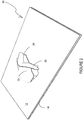
- a blank 10 is formed from a sheet of suitable substrate.
- suitable substrate includes all manner of foldable sheet material such as paperboard, corrugated board, cardboard, plastic, combinations thereof, and the like. It should be recognized that one or other numbers of blanks may be employed, for example, to provide a carton having a complementary locking mechanism described in more detail below.
- the blank 10 comprises a first panel 12 and a second panel 14.
- first panel 12 and the second panel 14 are shown as separate panels.
- first panel 12 and the second panel 14 may form part of the same blank and may be hingedly connected to one another by one or more additional panels.
- first panel and the second panel may form a composite panel of a carton.
- the carton comprises a plurality of panels forming a tubular structure having a plurality of walls including a top wall, a bottom wall and opposed side walls.
- the composite panel formed by the first panel and the second panel may form one of the plurality of walls of the tubular structure.
- each end of the tubular structure may be at least partially closed by one or more end closure panels.
- the first panel 12 comprises a first part F of a complementary locking mechanism.
- the first part F comprises a female tab 22 defined by a severance line such as a cut line 23.
- the female tab 22 is integrally formed with the first panel 12.
- the female tab 22 is struck from the first panel 12.
- the female tab 22 is hingedly coupled to the first panel 12. Although no fold line is shown in Figure 1 to connect between the female tab 22 and the first panel 12, either a linear or non-linear fold line may be used optionally to hingedly connect the female tab 22 to the first panel 12.
- the female tab 22 is foldable out of the plane of the first panel 12 to create an aperture "A" (see Figures 2 and 5 ) in the first panel 12.
- the female tab 22 comprises a recessed or concaved leading or free end 30; optionally, the recessed free end 30 is substantially V-shaped.
- the free end 30 comprises a first linear portion, a second linear portion and a curved, angled or otherwise non-straight portion, the non-straight portion is disposed between the first linear portion and the second linear portion to connect therebetween.
- the first linear portion is arranged with respect to the second linear portion so as to define a non-zero angle, such as an obtuse angle, therebetween.
- the orientation of the first and second linear portions is such that the first and second linear portions extend from the non-straight portion divergently toward the free edge 19 of the first panel 12.
- the angle between the first linear portion and the second linear portion is between ninety (90) degrees and one hundred eighty (180) degrees; optionally the angle is approximately one hundred forty (140) degrees.
- the second panel 14 comprises a second part M of a complementary locking mechanism.
- the second part M comprises a male tab 20 defined by a severance line such as a cut line 21.
- the male tab 20 is substantially arrow head-shaped.
- the male tab 20 comprises lobes or wings which provide shoulders for engaging with the first panel 12 so as to secure the male tab 20 and prevent, or at least inhibit, the male tab 20 from being withdrawn through the aperture "A" in the first panel 12 created by displacement of the female tab 22.
- the female tab 22 is shaped so as to accommodate the lobes or wings when folded and inserted through the first panel 12.
- the female tab 22 comprises shoulders which, when the female tab 22 is folded out of the plane of the first panel 12, define a widest point of the aperture "A" thus allowing the lobes to pass freely therethrough.
- the lobes of the male tab 20 engage with portions of the first panel 12 previously adjacent (before displacement of the female tab 22 out of the plane of the first panel 12) to the shoulders of the female tab 22.
- the female tab 22 maintains the lobes of the male tab 20 in position over the portions of the first panel 12.
- the male tab 20 is integrally formed with the second panel 14.
- the male tab 20 is struck from material forming the second panel 14 although in alternative embodiments the male tab may be joined to, and extend from, the free edge 25 of the second panel 14.
- the male tab 20 is hingedly coupled to the second panel 14 along a non-linear fold line 24a/26/24b.
- the male tab 20 is foldable about the non-linear fold line out of the plane of the second panel 14.
- the non-linear fold line comprises a first linear fold line 24a and a second linear fold line 24b.
- the first linear fold line 24a is arranged with respect to the second linear fold line 24b so as to define a non-zero angle, such as an obtuse angle, therebetween.
- the angle between the first linear fold line 24a and the second linear fold line 24b is between ninety (90) degrees and one hundred eighty (180) degrees; optionally the angle is approximately one hundred forty (140) degrees.
- the first linear fold line 24a is interconnected to the second linear fold line 24b by an arched, angled or otherwise non-straight cut line 26; that is to say the cut line 26 is interposed between the first linear fold line 24a and the second linear fold line 24b.
- the first and second linear fold lines 24a, 24b extend from the non-straight cut line 26 divergently toward the proximal end of the male tab 20, the proximal end being located at the end opposite to the free end 27.
- first and second linear fold lines 24a, 24b extend divergently away from the free end of the male tab 20.
- a weakened line such as a linear cutline 28extends from a vertex (or midpoint) of the cut line 26 towards the free or leading end (or nose) 27 of the male tab 20.
- the weakened line 28 stops short of the free end 27 of the male tab 20.
- the vertex or midpoint of the cut line 26 and the free end 27 of the male tab 20 define a linear dimension, height or length of the male tab 20.
- the weakened line 28 extends across approximately 80% to 85%, optionally 82%, of the linear dimension.
- the weakened line 28 terminates at a point approximately 2mm apart from the free end of the male tab 20.
- the free end 30 of the female tab 22 is shaped complementarily to the shape defined by the non-linear fold line 24a, 26, 24b of the male tab 20.
- the shape defined by the non-linear fold line 24a/24b/26 predisposes the male tab to fold about the weakened line 28 to become a substantially channel-shaped, non-planar structure.
- the free end 30 of the female tab 22 provides a mandrel or guide to encourage the male tab 20 to turn into the substantially channel-shaped structure.
- the locking device can be activated by folding operations on a straight line machine so that the locking device is not required to be rotated or inverted to complete its activation.
- the activation process is not limited to that described below and may be altered according to particular manufacturing requirements.
- the first panel 12 and the second panel 14 are brought into at least a partial overlapping relationship.
- a first or outside surface of the first panel 12 is disposed in contact with a second or inside surface of the second panel 14.
- the first panel 12 may be disposed internally of the second panel 14 such that the second panel 14 is placed outermost.
- the first surface of the first panel 12 is an outside surface while the second surface of the second panel 14 is an inside surface. In this way, the locking device in the deployed condition is disposed within an internal volume of the carton.
- the first panel 12 and the second panel 14 are arranged such that the female tab 22 is disposed on the male tab 20, in at least partial vertical registry therewith.
- the male tab 20 of the second part M is pressed or punched through the first panel 12. This causes the male tab 20 to fold about the non-linear fold lines 24a/24b/26 and be displaced out of the plane of the second panel 14.
- Displacing the male tab 20 allows the male tab 20 to be inserted into the aperture "A" and causes the female tab 22 to be thrust aside with respect to the first panel 12.
- a fold line 35 ( Figures 2 and 3 ) is created which extends between the opposed ends of the cutline 23.
- the region of the male tab 20 between the free end of the male tab 20 and a distal end of the cutline 28 also folds; a fold line is created in the region as a consequence of the male tab 20 folding about the non-linear fold line 24a/24b/26.
- the region may also form a lip or ridge.
- the region deforms, bends or folds partially over the female tab 22. This creates a flange for restricting upward movement, or unfolding, of the female tab 22.
- the free end 30 of the female tab 22 comprises a shape which assists in folding the male tab 20 about the weakened line 28 to form the channel-shaped structure.
- Each of the lobes or wings of the male tab 20 is disposed above a portion of the first panel 12 when in the folded condition, thus locking the first and second panels 12, 14 together.
- the male tab 20 is folded till it clears the female tab 22 and is brought into a braced position (shown in Figures 2-5 ) wherein the female tab 22 leans against the male tab 20.
- a braced position where the male tab 20 is braced by the female tab 20
- movement or unfolding of the male tab 20 is restricted. In this way a secure lock is formed between the first and second panels 12, 14.
- the male tab 20 being folded about the weakened line 28 allows itself to turn into a 3-dimensional, channel shaped structure which is resistant to unintentional unfolding, to crushing and to deformation. Such a locking device is resistant to disengagement by pulling the first and second panels 12, 14 apart.
- a first panel 112 comprises the first part F of a complementary locking mechanism substantially as described above in relation to the first embodiment of Figures 1 to 5 .
- the second embodiment also comprises a second panel 114 having a second part M of a complementary locking mechanism.
- the second part M comprises a male tab 120 hingedly coupled to the second panel 114 by a non-linear fold line which is formed of first and second linear fold lines 124a, 124b and a non-straight cut 126 connecting between the first and second fold lines 124a, 124b.
- the male tab 120 is struck from the second panel 114.
- the male tab 120 is foldable about the non-linear fold line 124a/124b/126 out of the plane of the second panel 114.
- the first linear fold line 124a is arranged with respect to the second linear fold line 124b so as to define a non-zero angle, such as an obtuse angle, therebetween.
- the angle between the first linear fold line 124a and the second linear fold line 124b is between ninety (90) degrees and one hundred eighty (180) degrees; optionally the angle is approximately one hundred forty (140) degrees.
- the first linear fold line 124a is interconnected to the second linear fold line 124b by an arched, angled or otherwise non-straight cut line 126; that is to say, the non-straight cut line 126 is interposed between the first linear fold line 124a and the second linear fold line 124b.
- a weakened line 128 extends from a vertex or midpoint of the arched cut line 126 towards a free end (or nose) of the male tab 120.
- the weakened line 128 terminates at a point spaced apart from the free end of the male tab 120.
- the vertex or midpoint of the arched cut line 126 and the free end of the male tab 120 define a linear dimension, height or length of the male tab.
- the weakened line 128 extends across approximately 65% to 80%, optionally 67%, of the linear dimension.
- the linear cutline 128 terminates at a point approximately 3.6mm apart from the free end of the male tab 120.
- a second panel 214 comprises a second part M of a complementary locking mechanism.
- the second part M comprises a male tab 220 hingedly coupled to the second panel 214 by a non-linear fold line 224a/224b/226.
- a weakened line 229 extends from a vertex or midpoint of the arched cut line 226 all the way to a free end (or nose) of the male tab 220.
- the weakened line 229 terminates at the free edge of the male tab 220.
- the distance between the vertex or midpoint of the arched cut line 226 and the free end of the male tab 220 defines a linear dimension, height or length of the male tab 220. In some embodiments the weakened line 229 extends across approximately 100% of the linear dimension.
- the third embodiment comprises a first panel 212 including a first part F of a complementary locking mechanism.
- the first part F comprises a female tab 222 defined by a severance line such as a cut line 223.
- the female tab 222 is struck from material forming the first panel 212.
- the female tab 222 is hingedly coupled to the first panel 212 by a fold line 231.
- the female tab 222 is foldable out of the plane of the first panel 212 to create an aperture in the first panel 212. When displaced out of the plane of the first panel 212, the female tab 222 is folded about fold line 231. It will be appreciated that the fold line 231 may be employed with any of the embodiments illustrated or described herein.
- a fourth embodiment in which a first panel 312 comprises the first part F of a complementary locking mechanism substantially as described above in relation to the first embodiment of Figures 1 to 5 .
- the fourth embodiment also comprises a second panel 314 having a second part M of a complementary locking mechanism.
- the second part M comprises a male tab 320 hingedly coupled to the second panel 314 by a non-linear fold line that is formed of a first linear fold line 324a, a second linear fold line 324b and a non-straight cut 326.
- the male tab 320 is struck from material forming the second panel 314.
- the male tab 320 is foldable out of the plane of the second panel 314.
- the distance between the vertex or midpoint of the non-straight cut line 326 and the free end of the male tab 320 define a linear dimension, height or length of the male tab.
- the weakened line 328 extends across approximately 50% to 65%, optionally 52%, of the linear dimension.
- the weakened line 328 terminates at a point approximately 5.2mm apart from the free end of the male tab 320.
- a first panel 412 comprises a first part F of a complementary locking mechanism substantially as described above in relation to the first embodiment of Figures 1 to 5 .
- the fifth embodiment also comprises a second panel 414 having a second part M of a complementary locking mechanism.
- the second part M comprises a male tab 420 hingedly coupled to the second panel 414 by a non-linear fold line.
- the vertex or midpoint of the non-straight cut line 426 and the free end of the male tab 420 define a linear dimension, height or length of the male tab.
- the linear cutline 428 extends across approximately 50% to 65%, optionally 52%, of the linear dimension.
- the weakened line 428 terminates at a point approximately 5.2mm from the free end of the male tab 420.
- the male tab 420 comprises a weakened line 429 which extends from a point adjacent to the terminal point of the weakened line 428 to the free end of the male tab 420.
- the weakened line 429 extends to the edge of the male tab 420; that is to say across, almost entirely, the remaining portion of the linear dimension.
- the weakened line 429 is collinear with the weakened line 428.
- a second panel 514 comprises a second part M of a complementary locking mechanism.
- the second part M comprises a male tab 520 hingedly coupled to the second panel 514 by a non-linear fold line which comprises a first linear fold line 524a, a second linear fold line 524b and a non-straight cut line 526.
- the male tab 520 is struck from material forming the second panel 514.
- the male tab 520 is foldable about the non-linear fold line 524a/524b/526 out of the plane of the second panel 514.
- the first linear fold line 524a is arranged with respect to the second linear fold line 524b so as to define a non-zero angle, such as an obtuse angle, therebetween.
- the first and second linear fold lines 524a, 524b extend from the non-straight cut line 526 divergently toward the free end of the male tab 520.
- the angle between the first linear fold line 524a and the second linear fold line 524b is between ninety (90) degrees and one hundred eighty (180) degrees; optionally the angle is approximately one hundred forty (140) degrees.
- the first linear fold line 524a is interconnected to the second linear fold line 524b by the non-straight cut line 526 which is inverted with respect to the corresponding non-straight cut lines in the foregoing embodiments; that is to say, the non-straight cut line 526 is interposed between the first linear fold line 524a and the second linear fold line 524b.
- the first linear fold line 524a, the second linear fold line 524b and the non-straight cut line 526 define a generally inverted V-shape.
- the inverted V-shape defined by the non-linear fold line 524a/524b/526 is a mirror image of the V-shape defined by the non-linear fold line tin the embodiment of Figure 1 .
- a weakened line 528 a linear cut line in Figure 8 , is provided in the male tab 520.
- the weakened line 528 is orientated to extend along a notional line extending from the midpoint of the cut line 526 to the free end of the male tab 520.
- the weakened line 528 terminates at a point spaced (e.g., at approximately 5.2mm) from the free end of the male tab 520.
- the weakened line 528 terminates at a point spaced (e.g., at approximately 5.2mm) from the midpoint of the cut line 526.
- the distance between the midpoint of the non-straight cut line 526 and the free end of the male tab 520 define a linear dimension, height or length of the male tab along the notional line.
- the weakened line 528 extends across approximately 30% to approximately 60%, optionally about 40% to about 50% (for example 42%) of the linear dimension.
- the sixth embodiment comprises a first panel 512 including a first part F of a complementary locking mechanism.
- the first part F comprises a female tab 522 defined by a severance line such as a cut line 523.
- the female tab 522 is integrally formed with the first panel 512.
- the female tab 522 is struck from material forming the first panel 512.
- the female tab 522 is foldably coupled to the first panel 512.
- the female tab 522 is foldable out of the plane of the first panel 512 to create an aperture in the first panel 512. When displaced out of the plane of the first panel 512 the female tab 522 is folded to create a fold line.
- the female tab 522 comprises a free end 530.
- the free end 530 is shaped complementarily to the non-linear fold line 524a/524b/526 defining the inverted V-shape.
- the linear portions of the free edge 530 extend from the non-straight portion of the free end 530 divergently away from the free edge 519 of the first panel 512.
- the free end 530 is bulged or convex unlike the free end 30 of the female tab 22 in the first embodiment.
- the female tab 522 forms a guide or mandrel for facilitating folding of the male tab 520 about the weakened line 528. It will be appreciated that the male tab 520 adopts a substantially channel-shaped or V-shaped configuration.
- the V-shape of the male tab 520 in this embodiment points away from the female tab 522, whereas in the foregoing embodiments of Figures 1 to 7B , the channel-shape or V-shape of the male tab 20, 120, 220, 320, 420 points towards or into the female tab 22, 122, 222, 322, 422.
- a seventh embodiment in which a second panel 614 comprises a second part M of a complementary locking mechanism.
- the second part M comprises a male tab 620 hingedly coupled to the second panel 614 by a non-linear fold line which comprises a first arcuate fold line 624a, a second arcuate fold line 624b and non-straight cut 626.
- the male tab 620 is struck from material forming the second panel 614.
- the male tab 620 is foldable about the non-linear or arched fold line 624a/624b/626 out of the plane of the second panel 614.
- the first curved fold line 624a is arranged with respect to the second curved fold line 624b so as to form part of a continuous arc.
- the first curved fold line 624a is interconnected to the second curved fold line 624b by an arched, U-shaped or otherwise non-straight cut line 626.
- the non-straight cut line 626 is interposed between the first curved fold line 624a and the second curved fold line 624b.
- the first curved fold line 624a, the second curved fold line 624b and the non-straight cut line 626 together define a continuous arc or curve, optionally a U-shape, although an inverted U-shape may be employed in alternative embodiments.
- the first curved fold line 624a, the second curved fold line 624b and the arcuate or non-straight cut line 626 together constitute a non-linear or arched fold line 624a/624b/626.
- the first and second curved fold lines extend from the non-straight cut 626 divergently away from the free edge 625 of the second panel 614.
- the first curved fold line 624a, the second curved fold line 624b and the non-straight cut line 626 define a generally U-shape whereas the first linear fold line 24a, the second linear fold line 24b and the non-straight cut line 26 of the first embodiment of Figure 1 define a generally V-shape.
- a first weakened line 628 is provided in the male tab 620.
- the first weakened line 628 is arranged to extend from an intermediate point of the non-straight cut line 626 and extends substantially radially outward from the arched cut line 626 towards a free end of the male tab 620.
- the first weakened line 628 terminates at a point spaced from the free end of the male tab 620.
- the distance between the vertex or midpoint of the non-straight cut line 626 and the free end of the male tab 620 define a linear dimension, height or length of the male tab 620.
- the first weakened line 628 extends across approximately 50% to 85%, optionally 70%, of the linear dimension.
- the weakened line 628 terminates at a point approximately 2mm from the free end of the male tab 620.
- a second weakened line 632a is provided in the male tab 620 on a first side of the first weakened line 628.
- the second weakened line 632a is spaced apart from the first weakened line 628 and is arranged in substantially parallel to the first weakened line 628.
- the second weakened line 632a is shorter than the first weakened line 628.
- the second linear cut line 632a terminates at a point spaced from the non-linear fold line 624a/624b/626.
- a third weakened line 632b is provided in the male tab 620 on a second side of the first weakened line 628.
- the third weakened line 632b is spaced apart from the first weakened line 628 and is arranged in substantially parallel to the first weakened line 628.
- the third weakened line 632b is shorter than the first weakened line 628.
- the third weakened line 632b terminates at a point spaced from the non-linear fold line 624a/624b626.
- the second and third weakened lines 632a, 632b facilitate folding or otherwise deforming of the male tab 620 into a curved or arcuate, channel-like shape.
- additional weakened lines may be provided in the male tab to facilitate folding.
- the seventh embodiment comprises a first panel 612 including a first part F of a complementary locking mechanism.
- the first part F comprises a female tab 622 defined by a severance line such as a cut line 623.
- the female tab 622 is integrally formed with the first panel 612.
- the female tab 622 is struck from material forming the first panel 612.
- the female tab 622 is foldably coupled to the first panel 612.
- the female tab 622 is foldable out of the plane of the first panel 612 to create an aperture in the first panel 612. When displaced out of the plane of the first panel 612, the female tab 622 is folded to create a fold line.
- the female tab 622 comprises a recessed or concave free end 630.
- the free end 630 is shaped complementarily in shape to the non-linear fold line 624a.624b/626.
- the recessed free end 630 of the female tab 622 provides a guide or mandrel for facilitating folding or deformation of the male tab 620 into a channel-shaped structure. It will be appreciated that the male tab 620 adopts a substantially U-shaped, channel-like configuration, whereas in the foregoing embodiments of Figures 1 to 8 the male tab 20, 120, 220, 320, 420, 520 adopts a substantially V-shaped, channel-like configuration.
- the size and shape of the panels, detachable sections and frangible connections may be adjusted to accommodate articles of differing size or shape.
- the weakened line 28, 128, 328 may extend across approximately 50% to 85%, or alternatively 65% to 85% or alternatively 50% to 80%, of the linear dimension of the respective male tab 20, 120, 320.
- the weakened line 28, 128, 328 may terminate at a point between approximately 2mm and approximately 5.2mm from the free end of the respective male tab 20, 120, 320.
- the weakened line 28, 128, 328 may terminate at a point between approximately 2mm and approximately 3.6mm from the free end of the respective male tab 20, 120, 320. In other embodiments, the weakened line 28, 128, 328 may terminate at a point between approximately 3.6mm and approximately 5.2mm from the free end of the respective male tab 20, 120, 320.
- additional weakened lines may be provided in the male tab to facilitate folding or deformation of the male tab to form an angular or arcuate shape; that is to say, folding the male tab so as to have a non-planar structure or shape.
- the male tab is provided with the one or more weakened lines each taking the form of, for example, a cut line which facilitates warping, or otherwise deformation, of the male tab into a channel-like, non-planar form as the male tab is folded about its non-linear fold line.
- the one or more weakened lines may be used with the invention. More particularly, the one weakened line, or each of the two or more weakened lines, may take the form of a single cut, a single score, a single half cut, a line of perforations, a line of cuts, a line of short slits, a line of half cuts, a line of scores, any combination thereof, or the like
- the female tab may be provided with a linear or non-linear fold line about which the female tab may be folded out of the plane of the first panel when thrust by the male tab.
- a non-linear fold line such as a V-shaped or arched fold line
- the female tab may also be provided with one or more weakened lines for facilitating warping, or otherwise deformation, of the female tab into a 3-dimensional channel structure, or otherwise non-planar structure, so that the structural strength of the female tab is increased.
- weakened line refers to a fold line or a severance line.
- fold line refers to any line that defines a hinge line in a foldable sheet material, such as paperboard, for facilitating folding of portions of a blank of sheet material with respect to one another, or otherwise indicating optimal panel folding locations on the blank.
- a fold line may be formed by a single cut, a single score, a single half cut, a line of perforations, a line of cuts, a line of short slits, a line of half cuts, a line of scores, any combination thereof, or the like.
- frangible line refers to any line that defines a separation line in a foldable sheet material, such as paperboard, for facilitating separation of portions of a blank of sheet material from one another, or otherwise indicating optimal separation locations on the blank.
- a frangible line may be formed by a single cut, a single half cut, a line of perforations, a line of cuts, a line of short slits, a line of half cuts, any combination thereof, or the like.
- a fold line or severance line such as cuts, scores, half cuts, slits, perforations or the like, may be dimensioned and arranged to provide the desired functionality.
- a line of perforations can be dimensioned or designed with degrees of weakness to define a fold line and/or a severance line.
- the line of perforations can be designed to facilitate folding and resist breaking, to facilitate folding and facilitate breaking with more effort, or to facilitate breaking with little effort.
Landscapes
- Engineering & Computer Science (AREA)
- Mechanical Engineering (AREA)
- Cartons (AREA)
- Making Paper Articles (AREA)
- Packages (AREA)
Claims (20)
- Dispositif de verrouillage pour carton, le dispositif de verrouillage comportant
une première partie (F) définie dans un premier panneau (12 ; 112 ; 212 ; 312; 412; 512; 612); et.
une seconde partie (M) associée à un second panneau (14 ; 114 ; 214 ; 314 ; 414; 514; 614),
la première partie comprenant une languette femelle (22 ; 112 ; 222 ; 322 ; 422; 522 ; 622) détachée du premier panneau et reliée d'une manière pliable à celui-ci, la languette femelle définissant une ouverture (A) dans le panneau quand elle quitte, par pliage, un plan du premier panneau,
la seconde partie comprenant une languette mâle (20 ; 120 ; 220 ; 320 ; 420 ; 520 ; 620), caractérisé en ce que la languette mâle est reliée d'une manière pliable au second panneau suivant une ligne de pliage non linéaire (26 ; 126 ; 226 ; 326 ; 426 ; 526 ; 626),
la languette mâle pouvant être pliée autour de la ligne de pliage non linéaire pour venir dans une position arc-boutée dans l'ouverture dans laquelle la languette femelle s'appuie contre la languette mâle afin de maintenir la languette mâle dans la position arc-boutée, grâce à quoi les premier et second panneaux sont fixés l'un à l'autre. - Dispositif de verrouillage selon la revendication 1, dans lequel la seconde partie comprend en outre au moins une ligne affaiblie (28 ; 128 ; 229 ; 328 ; 428 ; 528 ; 628, 632a, 632b) définie dans la languette mâle pour faciliter le pliage de la languette mâle autour de la ligne de pliage non linéaire.
- Dispositif de verrouillage selon la revendication 2, dans lequel la/les ligne(s) affaiblie(s) comprend/comprennent une outre deux lignes de pliage.
- Dispositif de verrouillage selon la revendication 3, dans lequel la/les ligne(s) de pliage comprend/comprennent une chose choisie dans le groupe consistant en une entaille unique, une encoche unique, une demi-entaille, une ligne de perforations, une ligne d'entailles, une ligne de courtes fentes, une ligne de demi-entailles, une ligne d'encoches et n'importe quelle combinaison de celles-ci.
- Dispositif de verrouillage selon la revendication 3, dans lequel la/les ligne(s) de pliage comprennent deux ou plus de deux lignes de pliage parallèles choisies chacune dans le groupe consistant en une entaille unique, une encoche unique, une demi-entaille, une ligne de perforations, une ligne d'entailles, une ligne de courtes fentes, une ligne de demi-entailles, une ligne d'encoches et n'importe quelle combinaison de celles-ci.
- Dispositif de verrouillage selon la revendication 1, dans lequel la ligne de pliage non linéaire comprend une première ligne de pliage linéaire (24a ; 124 ; 224a ; 324a ; 424a ; 524a ; 624a) et une second ligne de pliage linéaire (24b ; 124b ; 224b ; 324b ; 424B ; 524b ; 624b) conçues pour définir entre elles un angle obtus.
- Dispositif de verrouillage selon la revendication 6, dans lequel la ligne de pliage non linéaire comprend en outre une ligne de découpage (26 ; 126 ; 226 ; 326 ; 426 ; 526 ; 626) disposée entre la première ligne de pliage linéaire et la seconde ligne de pliage linéaire.
- Dispositif de verrouillage selon la revendication 1, dans lequel la ligne de pliage non linéaire comprend une première ligne de pliage courbe (624a) et une seconde ligne de pliage courbe (624b) conçues pour définir un arc continu avec une ligne de découpage (626) disposée entre celles-ci.
- Dispositif de verrouillage selon la revendication 7 ou 8, dans lequel la/les ligne(s) affaiblie(s) croise(nt) la ligne de pliage non linéaire.
- Dispositif de verrouillage selon la revendication 9, dans lequel la/les ligne(s) affaiblie(s) croise(nt) la ligne de découpage.
- Dispositif de verrouillage selon la revendication 1, dans lequel la/les ligne(s) affaiblie(s) (625, 632a, 632b) comprend/comprennent deux ou plus de deux lignes de pliage (628, 632a, 632b) disposées parallèlement les unes aux autres.
- Dispositif de verrouillage selon la revendication 1, dans lequel la languette femelle comprend une extrémité libre (30 ; 130 ; 230 ; 330 ; 430 ; 530 ; 630) disposée en butée sur la languette mâle quand la languette mâle est dans la position arc-boutée, l'extrémité libre de la languette femelle ayant une forme complémentaire de celle de la ligne de pliage non linéaire afin de former un mandrin pour plier la languette mâle et réaliser une structure non plane.
- Dispositif de verrouillage selon la revendication 12, dans lequel l'extrémité libre de la languette femelle a une forme non linéaire.
- Dispositif de verrouillage selon la revendication 13, dans lequel l'extrémité libre de la languette femelle est concave.
- Dispositif de verrouillage selon la revendication 13, dans lequel l'extrémité libre de la languette femelle est convexe.
- Dispositif de verrouillage selon la revendication 1, dans lequel la languette mâle est détachée du second panneau.
- Dispositif de verrouillage selon la revendication 1, dans lequel la languette mâle s'étend depuis un bord libre du second panneau.
- Flan pour former un carton, le flan comportant :un premier panneau (12 ; 112 ; 212 ; 312 ; 412 ; 512 ; 612) comprenant une première partie d'un dispositif de verrouillage ; et.un second panneau (14 ; 114 ; 214 ; 314 ; 414 ; 514 ; 614) comprenant une seconde partie d'un dispositif de verrouillage,la première partie comprenant une languette femelle détachée du premier panneau et reliée d'une manière pliable à celui-ci, la languette femelle (22 ; 122 ; 222 ; 322 ; 422 ; 522 ; 622) définissant une ouverture quand elle quitte, par pliage, un plan du premier panneau,la seconde partie comprenant une languette mâle (20 ; 120 ; 220 ; 320 ; 420 ; 520 ; 620), caractérisé en ce que la languette mâle est reliée d'une manière pliable au second panneau par une ligne de pliage non linéaire (26 ; 126 ; 226 ; 326 ; 426 ; 526 ; 626), la languette mâle pouvant être pliée autour de la ligne de pliage non linéaire pour venir dans une position arc-boutée dans l'ouverture dans laquelle la languette femelle s'appuie contre la languette mâle afin de maintenir la languette mâle dans la position arc-boutée, grâce à quoi les premier et second panneaux sont fixés l'un à l'autre.
- Flan selon la revendication 18, dans lequel la seconde partie comprend en outre au moins une ligne affaiblie (28 ; 128 ; 229 ; 328 ; 428 ; 528 ; 628, 632a, 632b) définie dans la languette mâle pour faciliter le pliage de la languette mâle autour de la ligne de pliage non linéaire.
- Flan selon la revendication 19, dans lequel la/les ligne(s) affaiblie(s) comprend/comprennent une ou plusieurs ligne(s) de pliage.
Applications Claiming Priority (2)
| Application Number | Priority Date | Filing Date | Title |
|---|---|---|---|
| US201461988446P | 2014-05-05 | 2014-05-05 | |
| PCT/US2015/028136 WO2015171376A1 (fr) | 2014-05-05 | 2015-04-29 | Dispositif de verrouillage de panneaux pour carton et son ébauche |
Publications (2)
| Publication Number | Publication Date |
|---|---|
| EP3140214A1 EP3140214A1 (fr) | 2017-03-15 |
| EP3140214B1 true EP3140214B1 (fr) | 2018-08-29 |
Family
ID=53175174
Family Applications (1)
| Application Number | Title | Priority Date | Filing Date |
|---|---|---|---|
| EP15721964.3A Active EP3140214B1 (fr) | 2014-05-05 | 2015-04-29 | Dispositif de verrouillage de panneaux pour carton et son ébauche |
Country Status (11)
| Country | Link |
|---|---|
| US (1) | US10099833B2 (fr) |
| EP (1) | EP3140214B1 (fr) |
| JP (1) | JP2017514766A (fr) |
| KR (1) | KR20170005422A (fr) |
| AR (1) | AR100320A1 (fr) |
| AU (1) | AU2015256438A1 (fr) |
| CA (1) | CA2948142A1 (fr) |
| CL (1) | CL2016002795A1 (fr) |
| MX (1) | MX379483B (fr) |
| TW (1) | TWI656072B (fr) |
| WO (1) | WO2015171376A1 (fr) |
Families Citing this family (10)
| Publication number | Priority date | Publication date | Assignee | Title |
|---|---|---|---|---|
| WO2018050806A1 (fr) | 2016-09-16 | 2018-03-22 | Koninklijke Philips N.V. | Appareil et procédé de détermination d'une réserve de débit fractionnaire |
| US10885772B2 (en) | 2017-12-21 | 2021-01-05 | Lumileds Llc | Road lighting |
| US11798406B2 (en) | 2018-03-21 | 2023-10-24 | Lumileds Llc | Road lighting |
| CN113631486B (zh) * | 2019-02-12 | 2024-01-23 | 维实洛克包装系统有限公司 | 面板互锁装置 |
| CN112978082B (zh) * | 2019-12-12 | 2024-06-11 | 上海紫丹印务有限公司 | 将两个面板连接在一起的双向锁扣装置及纸套 |
| WO2021236804A1 (fr) * | 2020-05-19 | 2021-11-25 | Westrock Shared Services, Llc | Agencement d'interverrouillage de panneau, carton et découpe de carton |
| CN111573001B (zh) * | 2020-06-12 | 2024-12-13 | 合肥远传包装科技有限公司 | 一种盒体 |
| USD980069S1 (en) | 2020-07-14 | 2023-03-07 | Ball Corporation | Metallic dispensing lid |
| US12168551B2 (en) | 2021-03-01 | 2024-12-17 | Ball Corporation | Metal container and end closure with seal |
| KR102796893B1 (ko) * | 2023-11-29 | 2025-04-22 | 박재형 | 의자용 휠 조립체 |
Citations (1)
| Publication number | Priority date | Publication date | Assignee | Title |
|---|---|---|---|---|
| US3380645A (en) * | 1967-05-05 | 1968-04-30 | Certipak Corp | Glueless interlocks for folding box panels |
Family Cites Families (10)
| Publication number | Priority date | Publication date | Assignee | Title |
|---|---|---|---|---|
| GB8401610D0 (en) * | 1984-01-20 | 1984-02-22 | Mead Corp | Panel interlocking means |
| US4723699A (en) * | 1986-05-16 | 1988-02-09 | Federal Paper Board Co., Inc. | Adjustable clasp lock |
| US4773540A (en) * | 1987-08-31 | 1988-09-27 | Manville Corporation | Carton panel locking arrangement |
| FR2641523A1 (fr) | 1988-10-07 | 1990-07-13 | 4 P Emballages France | Emballage du genre fourreau pour groupe de pots ou analogue, comportant des moyens de calage |
| JP4098382B2 (ja) * | 1997-08-29 | 2008-06-11 | ミードウエストヴェイコ・パッケージング・システムズ・エルエルシー | カートン |
| GB9814407D0 (en) | 1998-07-03 | 1998-09-02 | Mead Corp | Panel interlocking means |
| FR2824537B1 (fr) | 2001-05-10 | 2003-10-17 | Ar Carton Fegersheim | Structures d'interverrouillage entre deux panneaux superposes d'un flan de decoupe utilise pour l'enveloppement d'un lot de contenants et son procede de fermeture |
| US20080257945A1 (en) * | 2005-02-18 | 2008-10-23 | Jean-Michel Auclair | Interlocking Means for Carton Panels |
| WO2010045287A1 (fr) * | 2008-10-14 | 2010-04-22 | Graphic Packaging International, Inc. | Support possédant des éléments de verrouillage |
| GB0914435D0 (en) * | 2009-08-18 | 2009-09-30 | Meadwestvaco Packaging Systems | Carton and blank therefor |
-
2015
- 2015-04-29 EP EP15721964.3A patent/EP3140214B1/fr active Active
- 2015-04-29 WO PCT/US2015/028136 patent/WO2015171376A1/fr not_active Ceased
- 2015-04-29 CA CA2948142A patent/CA2948142A1/fr not_active Abandoned
- 2015-04-29 AU AU2015256438A patent/AU2015256438A1/en not_active Abandoned
- 2015-04-29 US US15/307,422 patent/US10099833B2/en active Active
- 2015-04-29 KR KR1020167032396A patent/KR20170005422A/ko not_active Withdrawn
- 2015-04-29 JP JP2016566693A patent/JP2017514766A/ja active Pending
- 2015-04-29 MX MX2016014442A patent/MX379483B/es unknown
- 2015-04-30 TW TW104113843A patent/TWI656072B/zh active
- 2015-05-04 AR ARP150101343A patent/AR100320A1/es active IP Right Grant
-
2016
- 2016-11-04 CL CL2016002795A patent/CL2016002795A1/es unknown
Patent Citations (1)
| Publication number | Priority date | Publication date | Assignee | Title |
|---|---|---|---|---|
| US3380645A (en) * | 1967-05-05 | 1968-04-30 | Certipak Corp | Glueless interlocks for folding box panels |
Also Published As
| Publication number | Publication date |
|---|---|
| TWI656072B (zh) | 2019-04-11 |
| CL2016002795A1 (es) | 2017-04-07 |
| MX2016014442A (es) | 2017-02-23 |
| JP2017514766A (ja) | 2017-06-08 |
| KR20170005422A (ko) | 2017-01-13 |
| AU2015256438A1 (en) | 2016-11-10 |
| WO2015171376A1 (fr) | 2015-11-12 |
| AR100320A1 (es) | 2016-09-28 |
| MX379483B (es) | 2025-03-10 |
| US20170057717A1 (en) | 2017-03-02 |
| US10099833B2 (en) | 2018-10-16 |
| CA2948142A1 (fr) | 2015-11-12 |
| TW201542426A (zh) | 2015-11-16 |
| EP3140214A1 (fr) | 2017-03-15 |
Similar Documents
| Publication | Publication Date | Title |
|---|---|---|
| EP3140214B1 (fr) | Dispositif de verrouillage de panneaux pour carton et son ébauche | |
| US10569947B2 (en) | Carton and carton blank and a handle structure therefor | |
| EP2361200B1 (fr) | Panier permettant de contenir des contenants | |
| US9022277B2 (en) | Carrier with locking features | |
| US9592942B2 (en) | Carton and carton blank | |
| US12065293B2 (en) | Carton with integral handle and package | |
| US9493268B2 (en) | Package with strap handle | |
| JP2009538798A (ja) | 物品保持機能部を有するカートン | |
| US9527642B2 (en) | Carton and carton blank | |
| US11220385B2 (en) | Carton and blank therefor | |
| WO2016099969A1 (fr) | Poignée confortable pour boîte pliante | |
| US11072474B2 (en) | Carton and blank therefor | |
| US20160122070A1 (en) | Carton, carton blank and handle structure therefor | |
| US11014726B2 (en) | Carton and carton blank | |
| US10279951B2 (en) | Carton and carton blank | |
| US20190144184A1 (en) | Carton having improved dispensing feature and blank therefor | |
| US20170217630A1 (en) | Carton and carton blank | |
| US20150307225A1 (en) | Locking arrangement, carton, blank and method | |
| EP3241783A1 (fr) | Carton comportant une caractéristique de distribution améliorée et ébauche correspondante | |
| US12157615B2 (en) | Carton and blank therefor | |
| US20230032095A1 (en) | Carton and blank therefor |
Legal Events
| Date | Code | Title | Description |
|---|---|---|---|
| STAA | Information on the status of an ep patent application or granted ep patent |
Free format text: STATUS: THE INTERNATIONAL PUBLICATION HAS BEEN MADE |
|
| PUAI | Public reference made under article 153(3) epc to a published international application that has entered the european phase |
Free format text: ORIGINAL CODE: 0009012 |
|
| STAA | Information on the status of an ep patent application or granted ep patent |
Free format text: STATUS: REQUEST FOR EXAMINATION WAS MADE |
|
| 17P | Request for examination filed |
Effective date: 20161102 |
|
| AK | Designated contracting states |
Kind code of ref document: A1 Designated state(s): AL AT BE BG CH CY CZ DE DK EE ES FI FR GB GR HR HU IE IS IT LI LT LU LV MC MK MT NL NO PL PT RO RS SE SI SK SM TR |
|
| AX | Request for extension of the european patent |
Extension state: BA ME |
|
| DAV | Request for validation of the european patent (deleted) | ||
| DAX | Request for extension of the european patent (deleted) | ||
| RAP1 | Party data changed (applicant data changed or rights of an application transferred) |
Owner name: WESTROCK PACKAGING SYSTEMS, LLC |
|
| GRAP | Despatch of communication of intention to grant a patent |
Free format text: ORIGINAL CODE: EPIDOSNIGR1 |
|
| STAA | Information on the status of an ep patent application or granted ep patent |
Free format text: STATUS: GRANT OF PATENT IS INTENDED |
|
| INTG | Intention to grant announced |
Effective date: 20171114 |
|
| GRAJ | Information related to disapproval of communication of intention to grant by the applicant or resumption of examination proceedings by the epo deleted |
Free format text: ORIGINAL CODE: EPIDOSDIGR1 |
|
| STAA | Information on the status of an ep patent application or granted ep patent |
Free format text: STATUS: REQUEST FOR EXAMINATION WAS MADE |
|
| GRAS | Grant fee paid |
Free format text: ORIGINAL CODE: EPIDOSNIGR3 |
|
| STAA | Information on the status of an ep patent application or granted ep patent |
Free format text: STATUS: GRANT OF PATENT IS INTENDED |
|
| GRAP | Despatch of communication of intention to grant a patent |
Free format text: ORIGINAL CODE: EPIDOSNIGR1 |
|
| INTC | Intention to grant announced (deleted) | ||
| INTG | Intention to grant announced |
Effective date: 20180503 |
|
| GRAA | (expected) grant |
Free format text: ORIGINAL CODE: 0009210 |
|
| STAA | Information on the status of an ep patent application or granted ep patent |
Free format text: STATUS: THE PATENT HAS BEEN GRANTED |
|
| AK | Designated contracting states |
Kind code of ref document: B1 Designated state(s): AL AT BE BG CH CY CZ DE DK EE ES FI FR GB GR HR HU IE IS IT LI LT LU LV MC MK MT NL NO PL PT RO RS SE SI SK SM TR |
|
| REG | Reference to a national code |
Ref country code: GB Ref legal event code: FG4D |
|
| REG | Reference to a national code |
Ref country code: CH Ref legal event code: EP |
|
| REG | Reference to a national code |
Ref country code: AT Ref legal event code: REF Ref document number: 1034854 Country of ref document: AT Kind code of ref document: T Effective date: 20180915 |
|
| REG | Reference to a national code |
Ref country code: IE Ref legal event code: FG4D |
|
| REG | Reference to a national code |
Ref country code: DE Ref legal event code: R096 Ref document number: 602015015560 Country of ref document: DE |
|
| REG | Reference to a national code |
Ref country code: NL Ref legal event code: FP |
|
| REG | Reference to a national code |
Ref country code: LT Ref legal event code: MG4D |
|
| PG25 | Lapsed in a contracting state [announced via postgrant information from national office to epo] |
Ref country code: NO Free format text: LAPSE BECAUSE OF FAILURE TO SUBMIT A TRANSLATION OF THE DESCRIPTION OR TO PAY THE FEE WITHIN THE PRESCRIBED TIME-LIMIT Effective date: 20181129 Ref country code: BG Free format text: LAPSE BECAUSE OF FAILURE TO SUBMIT A TRANSLATION OF THE DESCRIPTION OR TO PAY THE FEE WITHIN THE PRESCRIBED TIME-LIMIT Effective date: 20181129 Ref country code: IS Free format text: LAPSE BECAUSE OF FAILURE TO SUBMIT A TRANSLATION OF THE DESCRIPTION OR TO PAY THE FEE WITHIN THE PRESCRIBED TIME-LIMIT Effective date: 20181229 Ref country code: FI Free format text: LAPSE BECAUSE OF FAILURE TO SUBMIT A TRANSLATION OF THE DESCRIPTION OR TO PAY THE FEE WITHIN THE PRESCRIBED TIME-LIMIT Effective date: 20180829 Ref country code: LT Free format text: LAPSE BECAUSE OF FAILURE TO SUBMIT A TRANSLATION OF THE DESCRIPTION OR TO PAY THE FEE WITHIN THE PRESCRIBED TIME-LIMIT Effective date: 20180829 Ref country code: GR Free format text: LAPSE BECAUSE OF FAILURE TO SUBMIT A TRANSLATION OF THE DESCRIPTION OR TO PAY THE FEE WITHIN THE PRESCRIBED TIME-LIMIT Effective date: 20181130 Ref country code: RS Free format text: LAPSE BECAUSE OF FAILURE TO SUBMIT A TRANSLATION OF THE DESCRIPTION OR TO PAY THE FEE WITHIN THE PRESCRIBED TIME-LIMIT Effective date: 20180829 Ref country code: SE Free format text: LAPSE BECAUSE OF FAILURE TO SUBMIT A TRANSLATION OF THE DESCRIPTION OR TO PAY THE FEE WITHIN THE PRESCRIBED TIME-LIMIT Effective date: 20180829 |
|
| REG | Reference to a national code |
Ref country code: AT Ref legal event code: MK05 Ref document number: 1034854 Country of ref document: AT Kind code of ref document: T Effective date: 20180829 |
|
| PG25 | Lapsed in a contracting state [announced via postgrant information from national office to epo] |
Ref country code: AL Free format text: LAPSE BECAUSE OF FAILURE TO SUBMIT A TRANSLATION OF THE DESCRIPTION OR TO PAY THE FEE WITHIN THE PRESCRIBED TIME-LIMIT Effective date: 20180829 Ref country code: LV Free format text: LAPSE BECAUSE OF FAILURE TO SUBMIT A TRANSLATION OF THE DESCRIPTION OR TO PAY THE FEE WITHIN THE PRESCRIBED TIME-LIMIT Effective date: 20180829 Ref country code: HR Free format text: LAPSE BECAUSE OF FAILURE TO SUBMIT A TRANSLATION OF THE DESCRIPTION OR TO PAY THE FEE WITHIN THE PRESCRIBED TIME-LIMIT Effective date: 20180829 |
|
| PG25 | Lapsed in a contracting state [announced via postgrant information from national office to epo] |
Ref country code: PL Free format text: LAPSE BECAUSE OF FAILURE TO SUBMIT A TRANSLATION OF THE DESCRIPTION OR TO PAY THE FEE WITHIN THE PRESCRIBED TIME-LIMIT Effective date: 20180829 Ref country code: EE Free format text: LAPSE BECAUSE OF FAILURE TO SUBMIT A TRANSLATION OF THE DESCRIPTION OR TO PAY THE FEE WITHIN THE PRESCRIBED TIME-LIMIT Effective date: 20180829 Ref country code: AT Free format text: LAPSE BECAUSE OF FAILURE TO SUBMIT A TRANSLATION OF THE DESCRIPTION OR TO PAY THE FEE WITHIN THE PRESCRIBED TIME-LIMIT Effective date: 20180829 Ref country code: ES Free format text: LAPSE BECAUSE OF FAILURE TO SUBMIT A TRANSLATION OF THE DESCRIPTION OR TO PAY THE FEE WITHIN THE PRESCRIBED TIME-LIMIT Effective date: 20180829 Ref country code: CZ Free format text: LAPSE BECAUSE OF FAILURE TO SUBMIT A TRANSLATION OF THE DESCRIPTION OR TO PAY THE FEE WITHIN THE PRESCRIBED TIME-LIMIT Effective date: 20180829 Ref country code: RO Free format text: LAPSE BECAUSE OF FAILURE TO SUBMIT A TRANSLATION OF THE DESCRIPTION OR TO PAY THE FEE WITHIN THE PRESCRIBED TIME-LIMIT Effective date: 20180829 |
|
| PG25 | Lapsed in a contracting state [announced via postgrant information from national office to epo] |
Ref country code: SM Free format text: LAPSE BECAUSE OF FAILURE TO SUBMIT A TRANSLATION OF THE DESCRIPTION OR TO PAY THE FEE WITHIN THE PRESCRIBED TIME-LIMIT Effective date: 20180829 Ref country code: DK Free format text: LAPSE BECAUSE OF FAILURE TO SUBMIT A TRANSLATION OF THE DESCRIPTION OR TO PAY THE FEE WITHIN THE PRESCRIBED TIME-LIMIT Effective date: 20180829 Ref country code: SK Free format text: LAPSE BECAUSE OF FAILURE TO SUBMIT A TRANSLATION OF THE DESCRIPTION OR TO PAY THE FEE WITHIN THE PRESCRIBED TIME-LIMIT Effective date: 20180829 |
|
| REG | Reference to a national code |
Ref country code: DE Ref legal event code: R097 Ref document number: 602015015560 Country of ref document: DE |
|
| PLBE | No opposition filed within time limit |
Free format text: ORIGINAL CODE: 0009261 |
|
| STAA | Information on the status of an ep patent application or granted ep patent |
Free format text: STATUS: NO OPPOSITION FILED WITHIN TIME LIMIT |
|
| 26N | No opposition filed |
Effective date: 20190531 |
|
| PG25 | Lapsed in a contracting state [announced via postgrant information from national office to epo] |
Ref country code: SI Free format text: LAPSE BECAUSE OF FAILURE TO SUBMIT A TRANSLATION OF THE DESCRIPTION OR TO PAY THE FEE WITHIN THE PRESCRIBED TIME-LIMIT Effective date: 20180829 |
|
| REG | Reference to a national code |
Ref country code: CH Ref legal event code: PL |
|
| REG | Reference to a national code |
Ref country code: BE Ref legal event code: MM Effective date: 20190430 |
|
| PG25 | Lapsed in a contracting state [announced via postgrant information from national office to epo] |
Ref country code: MC Free format text: LAPSE BECAUSE OF FAILURE TO SUBMIT A TRANSLATION OF THE DESCRIPTION OR TO PAY THE FEE WITHIN THE PRESCRIBED TIME-LIMIT Effective date: 20180829 Ref country code: LU Free format text: LAPSE BECAUSE OF NON-PAYMENT OF DUE FEES Effective date: 20190429 |
|
| PG25 | Lapsed in a contracting state [announced via postgrant information from national office to epo] |
Ref country code: LI Free format text: LAPSE BECAUSE OF NON-PAYMENT OF DUE FEES Effective date: 20190430 Ref country code: CH Free format text: LAPSE BECAUSE OF NON-PAYMENT OF DUE FEES Effective date: 20190430 |
|
| PG25 | Lapsed in a contracting state [announced via postgrant information from national office to epo] |
Ref country code: BE Free format text: LAPSE BECAUSE OF NON-PAYMENT OF DUE FEES Effective date: 20190430 |
|
| PG25 | Lapsed in a contracting state [announced via postgrant information from national office to epo] |
Ref country code: TR Free format text: LAPSE BECAUSE OF FAILURE TO SUBMIT A TRANSLATION OF THE DESCRIPTION OR TO PAY THE FEE WITHIN THE PRESCRIBED TIME-LIMIT Effective date: 20180829 |
|
| PG25 | Lapsed in a contracting state [announced via postgrant information from national office to epo] |
Ref country code: IE Free format text: LAPSE BECAUSE OF NON-PAYMENT OF DUE FEES Effective date: 20190429 |
|
| PG25 | Lapsed in a contracting state [announced via postgrant information from national office to epo] |
Ref country code: PT Free format text: LAPSE BECAUSE OF FAILURE TO SUBMIT A TRANSLATION OF THE DESCRIPTION OR TO PAY THE FEE WITHIN THE PRESCRIBED TIME-LIMIT Effective date: 20181229 |
|
| PG25 | Lapsed in a contracting state [announced via postgrant information from national office to epo] |
Ref country code: CY Free format text: LAPSE BECAUSE OF FAILURE TO SUBMIT A TRANSLATION OF THE DESCRIPTION OR TO PAY THE FEE WITHIN THE PRESCRIBED TIME-LIMIT Effective date: 20180829 |
|
| PG25 | Lapsed in a contracting state [announced via postgrant information from national office to epo] |
Ref country code: MT Free format text: LAPSE BECAUSE OF FAILURE TO SUBMIT A TRANSLATION OF THE DESCRIPTION OR TO PAY THE FEE WITHIN THE PRESCRIBED TIME-LIMIT Effective date: 20180829 Ref country code: HU Free format text: LAPSE BECAUSE OF FAILURE TO SUBMIT A TRANSLATION OF THE DESCRIPTION OR TO PAY THE FEE WITHIN THE PRESCRIBED TIME-LIMIT; INVALID AB INITIO Effective date: 20150429 |
|
| PG25 | Lapsed in a contracting state [announced via postgrant information from national office to epo] |
Ref country code: MK Free format text: LAPSE BECAUSE OF FAILURE TO SUBMIT A TRANSLATION OF THE DESCRIPTION OR TO PAY THE FEE WITHIN THE PRESCRIBED TIME-LIMIT Effective date: 20180829 |
|
| REG | Reference to a national code |
Ref country code: DE Ref legal event code: R082 Ref document number: 602015015560 Country of ref document: DE Representative=s name: GRAPE & SCHWARZENSTEINER, DE |
|
| P01 | Opt-out of the competence of the unified patent court (upc) registered |
Effective date: 20230601 |
|
| REG | Reference to a national code |
Ref country code: DE Ref legal event code: R082 Ref document number: 602015015560 Country of ref document: DE |
|
| PGFP | Annual fee paid to national office [announced via postgrant information from national office to epo] |
Ref country code: NL Payment date: 20250427 Year of fee payment: 11 |
|
| PGFP | Annual fee paid to national office [announced via postgrant information from national office to epo] |
Ref country code: DE Payment date: 20250429 Year of fee payment: 11 |
|
| PGFP | Annual fee paid to national office [announced via postgrant information from national office to epo] |
Ref country code: GB Payment date: 20250428 Year of fee payment: 11 |
|
| PGFP | Annual fee paid to national office [announced via postgrant information from national office to epo] |
Ref country code: IT Payment date: 20250422 Year of fee payment: 11 |
|
| PGFP | Annual fee paid to national office [announced via postgrant information from national office to epo] |
Ref country code: FR Payment date: 20250425 Year of fee payment: 11 |