EP3140486B1 - Tür, fenster oder fassadenelement mit einem dichtungssystem - Google Patents
Tür, fenster oder fassadenelement mit einem dichtungssystem Download PDFInfo
- Publication number
- EP3140486B1 EP3140486B1 EP15721641.7A EP15721641A EP3140486B1 EP 3140486 B1 EP3140486 B1 EP 3140486B1 EP 15721641 A EP15721641 A EP 15721641A EP 3140486 B1 EP3140486 B1 EP 3140486B1
- Authority
- EP
- European Patent Office
- Prior art keywords
- seal
- window
- sealing
- door
- stop
- Prior art date
- Legal status (The legal status is an assumption and is not a legal conclusion. Google has not performed a legal analysis and makes no representation as to the accuracy of the status listed.)
- Active
Links
Images



Classifications
-
- E—FIXED CONSTRUCTIONS
- E06—DOORS, WINDOWS, SHUTTERS, OR ROLLER BLINDS IN GENERAL; LADDERS
- E06B—FIXED OR MOVABLE CLOSURES FOR OPENINGS IN BUILDINGS, VEHICLES, FENCES OR LIKE ENCLOSURES IN GENERAL, e.g. DOORS, WINDOWS, BLINDS, GATES
- E06B3/00—Window sashes, door leaves, or like elements for closing wall or like openings; Layout of fixed or moving closures, e.g. windows in wall or like openings; Features of rigidly-mounted outer frames relating to the mounting of wing frames
- E06B3/04—Wing frames not characterised by the manner of movement
- E06B3/263—Frames with special provision for insulation
- E06B3/26301—Frames with special provision for insulation with prefabricated insulating strips between two metal section members
- E06B3/26303—Frames with special provision for insulation with prefabricated insulating strips between two metal section members with thin strips, e.g. defining a hollow space between the metal section members
-
- E—FIXED CONSTRUCTIONS
- E06—DOORS, WINDOWS, SHUTTERS, OR ROLLER BLINDS IN GENERAL; LADDERS
- E06B—FIXED OR MOVABLE CLOSURES FOR OPENINGS IN BUILDINGS, VEHICLES, FENCES OR LIKE ENCLOSURES IN GENERAL, e.g. DOORS, WINDOWS, BLINDS, GATES
- E06B7/00—Special arrangements or measures in connection with doors or windows
- E06B7/16—Sealing arrangements on wings or parts co-operating with the wings
- E06B7/22—Sealing arrangements on wings or parts co-operating with the wings by means of elastic edgings, e.g. elastic rubber tubes; by means of resilient edgings, e.g. felt or plush strips, resilient metal strips
- E06B7/23—Plastic, sponge rubber, or like strips or tubes
- E06B7/2305—Plastic, sponge rubber, or like strips or tubes with an integrally formed part for fixing the edging
- E06B7/2312—Plastic, sponge rubber, or like strips or tubes with an integrally formed part for fixing the edging with two or more sealing-lines or -planes between the wing and part co-operating with the wing
-
- E—FIXED CONSTRUCTIONS
- E06—DOORS, WINDOWS, SHUTTERS, OR ROLLER BLINDS IN GENERAL; LADDERS
- E06B—FIXED OR MOVABLE CLOSURES FOR OPENINGS IN BUILDINGS, VEHICLES, FENCES OR LIKE ENCLOSURES IN GENERAL, e.g. DOORS, WINDOWS, BLINDS, GATES
- E06B3/00—Window sashes, door leaves, or like elements for closing wall or like openings; Layout of fixed or moving closures, e.g. windows in wall or like openings; Features of rigidly-mounted outer frames relating to the mounting of wing frames
- E06B3/04—Wing frames not characterised by the manner of movement
- E06B3/263—Frames with special provision for insulation
- E06B2003/26349—Details of insulating strips
- E06B2003/2635—Specific form characteristics
- E06B2003/26352—Specific form characteristics hollow
-
- E—FIXED CONSTRUCTIONS
- E06—DOORS, WINDOWS, SHUTTERS, OR ROLLER BLINDS IN GENERAL; LADDERS
- E06B—FIXED OR MOVABLE CLOSURES FOR OPENINGS IN BUILDINGS, VEHICLES, FENCES OR LIKE ENCLOSURES IN GENERAL, e.g. DOORS, WINDOWS, BLINDS, GATES
- E06B3/00—Window sashes, door leaves, or like elements for closing wall or like openings; Layout of fixed or moving closures, e.g. windows in wall or like openings; Features of rigidly-mounted outer frames relating to the mounting of wing frames
- E06B3/04—Wing frames not characterised by the manner of movement
- E06B3/263—Frames with special provision for insulation
- E06B2003/26349—Details of insulating strips
- E06B2003/26387—Performing extra functions
- E06B2003/26389—Holding sealing strips or forming sealing abutments
-
- E—FIXED CONSTRUCTIONS
- E06—DOORS, WINDOWS, SHUTTERS, OR ROLLER BLINDS IN GENERAL; LADDERS
- E06B—FIXED OR MOVABLE CLOSURES FOR OPENINGS IN BUILDINGS, VEHICLES, FENCES OR LIKE ENCLOSURES IN GENERAL, e.g. DOORS, WINDOWS, BLINDS, GATES
- E06B3/00—Window sashes, door leaves, or like elements for closing wall or like openings; Layout of fixed or moving closures, e.g. windows in wall or like openings; Features of rigidly-mounted outer frames relating to the mounting of wing frames
- E06B3/54—Fixing of glass panes or like plates
- E06B3/58—Fixing of glass panes or like plates by means of borders, cleats, or the like
- E06B3/62—Fixing of glass panes or like plates by means of borders, cleats, or the like of rubber-like elastic cleats
- E06B2003/6217—Fixing of glass panes or like plates by means of borders, cleats, or the like of rubber-like elastic cleats with specific fixing means
- E06B2003/6223—Fixing of glass panes or like plates by means of borders, cleats, or the like of rubber-like elastic cleats with specific fixing means with protruding parts anchored in grooves
-
- E—FIXED CONSTRUCTIONS
- E06—DOORS, WINDOWS, SHUTTERS, OR ROLLER BLINDS IN GENERAL; LADDERS
- E06B—FIXED OR MOVABLE CLOSURES FOR OPENINGS IN BUILDINGS, VEHICLES, FENCES OR LIKE ENCLOSURES IN GENERAL, e.g. DOORS, WINDOWS, BLINDS, GATES
- E06B7/00—Special arrangements or measures in connection with doors or windows
- E06B7/16—Sealing arrangements on wings or parts co-operating with the wings
- E06B7/22—Sealing arrangements on wings or parts co-operating with the wings by means of elastic edgings, e.g. elastic rubber tubes; by means of resilient edgings, e.g. felt or plush strips, resilient metal strips
- E06B7/23—Plastic, sponge rubber, or like strips or tubes
- E06B7/2305—Plastic, sponge rubber, or like strips or tubes with an integrally formed part for fixing the edging
- E06B7/2307—Plastic, sponge rubber, or like strips or tubes with an integrally formed part for fixing the edging with a single sealing-line or -plane between the wing and the part co-operating with the wing
- E06B7/2309—Plastic, sponge rubber, or like strips or tubes with an integrally formed part for fixing the edging with a single sealing-line or -plane between the wing and the part co-operating with the wing with a hollow sealing part
Definitions
- the present invention relates to a door, a window or a facade element with a sealing system for the rebate according to the preamble of claim 1.
- a door according to the preamble of claim 1 is in DE 10 2012 111 005 A1 disclosed.
- Doors, windows or facade elements of the type mentioned have been known for a long time.
- An important structural feature of such doors, windows or facade elements are (usually mitred) profile bars from which the window frame and/or the sash frame is assembled.
- the profile bars are usually cut to length from composite profiles.
- a thermally separated profile system for door and window constructions with a sealing system in the rebate space between the blind and casement frame is then created from the blind and casement frame bars.
- the composite profiles of the blind and/or sash frame spars consist of at least one metallic outer profile, preferably additionally a metallic middle profile and a metallic inner profile, each of which has at least one insulating area that reduces the heat transfer, Example of one or more Kunststofflsoliersteg connected to each other.
- the gap in the rebate space between the frame and the casement frame (spar) is usually sealed with a center seal (centre seal system).
- a center seal centre seal system
- voluminous center seals with hollow chambers made of coextruded material are known.
- Another common type of seal referred to as a butt seal system, uses two relatively small seals on the outer faces of the profiles. The thermal insulation of these solutions should be further improved or the heat transfer should be reduced.
- the sealing system has at least one or - and this is particularly advantageous - two pairs of seals, each consisting of a first seal on the window frame and a seal on the casement frame, which initially together have at least one Form a center seal, which the rebate space bridges in a sealed manner when the sash is closed.
- Each of the two seals is attached separately to the respective profile with a tongue and groove connection. If necessary, the two pairs of seals are fastened to the blind and/or sash frame bars in grooves of insulating bars.
- At least one of the two seals also has a stop seal area.
- This rebate seal area is provided with a tongue and groove connection on an insulating bar of the sash frame strut (or the window frame strut).
- one of the two seals of the or each pair of seals is designed as a seal stop, which has a base bar and a stop bar extending at an angle of greater than 60° to the base bar, and the second seal of the or each pair of seals is designed as a lip seal which has a base section and two sealing lips extending at an angle thereto, in particular substantially perpendicularly.
- the composite profile system is particularly preferably designed as a "three-shell system", consisting of two insulating zones with a double seal pair arrangement.
- An EPDM or TPE or a comparable plastic in different shore hardness is used as the preferred material for manufacturing the seals, foamed or unfoamed, with or without hollow chamber.
- Multi-area seals are also conceivable, in which combinations of materials (foamed or non-foamed) are produced simply or in a coextrusion process.
- All metal profiles are preferably made as extruded aluminum profiles. Alternatively, production from a different material such as steel and/or a different manufacturing process is also possible.
- All insulating bars are preferably made of a plastic material such as polyamide (PA66, PA6, PPA), polyester (PET, PBT), polyolefins (PP) or polyvinyl chloride (PVC), so that an extensive thermal separation between the adjacent metal profiles is achieved .
- a plastic material such as polyamide (PA66, PA6, PPA), polyester (PET, PBT), polyolefins (PP) or polyvinyl chloride (PVC), so that an extensive thermal separation between the adjacent metal profiles is achieved .
- All insulating bars can - but do not necessarily have to - have at least one hollow chamber. They can also each be combined in an insulating strip level by transverse strips to form a type of higher-level insulating strip.
- the insulating bars of the insulating bar zones can advantageously each lie in one plane. This is advantageous because it ensures a clear structure, but is not mandatory.
- one, several or all of the seals of the seal pairs are inserted with a seal base into a seal groove of the insulating strips. This is advantageous because the insulating bars do not protrude into the rebate area. However, it would also be conceivable, in a less preferred embodiment, to provide the seals with grooves in which protruding pins of the insulating bars would then engage.
- At least one of the seals of each pair of seals has one or more hollow chambers, as a result of which the thermal insulation is additionally improved.
- FIG. 1 shows a door 1 which has a pivotable and/or rotatable wing with a wing frame 2 and a frame 3 on which the wing is articulated with one or more fittings.
- the present invention can also be used with windows or facade elements or the like.
- the window frame 3 of this door 1 has window frame bars 4 , 5 and 6 .
- the casement 2 of the casement has a vertical casement spar 7 on the handle side and another vertical casement spar 8 on the hinge side.
- the casement 2 has an upper horizontal casement spar 9 and a lower horizontal casement spar 10 .
- the wing frame struts 6, 7, 8 are each joined together to form the wing frame 2 - here by corner connectors (not shown here) - so that a filling, such as glazing, can be used in the wing frame 2 (not shown here).
- a window frame spar 4 and a sash frame spar 5 of the door 1 are shown in section. Between the window frame spar 4 and the casement spar 5, a rebate space F is formed in the manner of a gap. This gap should be sealing be bypassed.
- the window frame spar 4 has a first metal profile 11—a first outer profile—that is connected to a metal center profile 12 via at least one or more first insulating bars (aligned here in parallel) 13a, 13b. These insulating strips 13a, b between the first metallic outer profile and the metallic central profile 12 form a first insulating strip zone I or level in the frame member 10 .
- a second metal profile 14, another outer profile - is also connected to the metal center profile 12 via at least one or more second (here parallel) insulating webs 15a, b.
- the insulating strips 15a, b between the second metal profile 14 and the central profile 12 form a second insulating strip zone II or plane in the frame member 10 .
- the metal profiles of the window frame spar 4 have hollow chambers, which is advantageous for thermal insulation
- In 2 have - for example - both insulating strip zones I, II on the window frame beam such insulating strips 13a, b; 15a, b, whose respective end sections are positively and non-positively connected to an associated groove of the metal profiles.
- the other frame members 5, 6 of the door or window are preferably constructed exactly like the frame member 4 described.
- the casement spar 7 has a first metal profile 17 as an outer profile. At least one hollow chamber 18 is formed in this. It also has a second metallic outer profile 19 in which at least one hollow chamber 20 is also preferably formed. A third metal profile, a central profile 21, is arranged between the two metal profiles 17 and 19, in which at least one hollow chamber 22 is also preferably formed.
- These metal profiles 17, 19, 21 can alternatively be designed without hollow chambers or each have several hollow chambers. If necessary, the hollow chambers reduce the heat transfer between the rooms adjacent to the door or the window or the facade element and simply allow the arrangement of corner connectors or the like.
- the first metal profile 17 is in turn connected to the metal center profile 21 via at least one or more first insulating strips (aligned here in parallel) 23a, b tied together. These insulating bars 23a, b between the first metal outer profile 17 and the metal middle profile 21 form a first insulating bar zone III or level in the sash frame spar 7.
- the second metal outer profile 19 is also connected to the metal middle profile 21 via at least one or more second (here parallel) ) Insulating bars 24a, b connected.
- the insulating strips 24a, b between the second metallic outer profile 19 and the metallic central profile 21 form a second insulating strip zone IV or level in the wing frame member 7 .
- the insulating strip zone III of the casement profile bar 7 has the insulating strips 23a, b, the respective end sections 25 of which are connected in a positive and non-positive manner to a groove 26 of the adjoining metal profile (outer profile or central profile), so that in each case a cf. Coordinate system in Fig. ) or in a direction orthogonal to the cross-sectional plane of the composite profile 4 results in a shear-resistant connection between the insulating bars and the adjoining metal profile.
- This connection is also referred to below as a shear-resistant connection. It provides shear resistance against the forces occurring due to dilatation on a window or door or the like.
- the insulating bars 24a, b of the second insulating bar zone IV of the sash frame spar 7 between the second metal outer profile and the metal middle profile 21 form a separation zone between the insulating bars and the second 19 outer profile, in which a drawerless sliding guide allows a relative movement.
- the separating zone can also be formed between the insulating bars 23a, b and the other Metzall profile or outer profile and the central profile 21.
- the insulating bars 24a, b are positioned in the y and x direction (relative to the coordinate system in 2 ) positively connected to the second metallic outer profile by a piping connection 27.
- a sliding guide is formed in this way.
- the shear strength in the sliding guide orthogonal to the cross-sectional plane of the composite profile can, but does not have to, approach zero.
- Such a sliding guide is colloquially referred to as a "slideless connection”.
- the arrangement of the drawerless connection - here in the insulating bar level IV - is to be understood as an example.
- the drawerless connection can also be arranged in insulating bar level III or in both insulating bar levels III, IV or on be trained in a different way.
- a slideless connection can also be dispensed with if the problem of compensating for dilatation is solved in some other way or not at all.
- the casement profile also has a holding strip 28, by which the filling, such as glazing, is held.
- the insulating bar levels I and II of the window frame profile and the insulating bar levels III and IV of the sash frame profile correspond to each other.
- an advantageous sealing system is also arranged to seal the gap of the rebate space F.
- figure 3 shows an enlarged representation of the rebate space F and the insulating zones of the composite profile system adjacent to the rebate space 2 .
- the sealing system in the rebate space F between the sash frame spar 7 and the frame spar 4 has two pairs of seals, each consisting of two seals 29a, 30a or 29b, 30b, one of the two seals on the frame spar 4 and the other seal on the sash frame spar 7 is arranged.
- each of the two insulating zones I and II or III and IV there is one of the pairs of seals, each with two different seals 29a, 30a and 29b, 30b.
- the two pairs of seals have the same structure, but each have two different seals 29a or 29b and 30a or 30b.
- the pairs of seals are of the same design in this way. However, their arrangement in the rebate area is different.
- the first seal 29a - referred to below as the seal stop - is arranged on the window frame member 4 - and the second seal 30a - referred to below as the lip seal - on the casement frame member 7.
- the first seal - the seal stop - 29b on the Casement frame spar 7 is arranged and the second seal 30b, referred to as a lip seal, on the frame spar 4.
- Each pair of seals forms between them a sealing chamber 34a, b that is closed almost all around when the sash is in the closed state with a web 59 of the sash frame spar or the window frame spar.
- another sealing chamber 35 is also advantageously formed between the pairs of seals. In this way, three sealing chambers 34a, 35, 34b adjoining one another perpendicularly to the door or window (main) plane are formed in the rebate space.
- stop areas A1, A2, A3, A4 are formed in the rebate space, which interrupt the gap that the rebate space would otherwise form between the blind and the sash frame spar when the sash is closed.
- the two outer stop areas A1, A4 are each formed between a metal profile of the window frame spar 4 or the casement spar 7 and one of the seals 30a, 30b.
- the two other (middle) stop areas A2, A3, on the other hand, are formed directly between the two seals 29a, 30a or 29b, 30b of each pair of seals.
- FIG 4 shows the first seal 29a or b of one pair of seals.
- This seal is also referred to below as a seal stop.
- the sealing stop has a base web 38, preferably a retaining foot 36 formed thereon, and a stop web 37 extending at an angle greater than 60°, in particular at an angle of 90°, to the base web 35.
- the base web 38 here has two areas of different thickness on both sides of the stop web 37 .
- the retaining foot 36 is designed for latching engagement in a groove 39 directed towards the rebate space F in the respective associated insulating strip 13a, 24a.
- figure 5 shows the second seal 30a, b of the two seal pairs, which forms a lip seal.
- the seal 30a, b designed as a lip seal has a base section 40 and two sealing lips 41 and 42 extending at an angle thereto, in particular substantially perpendicularly.
- the sealing lip 41 (in interaction with the stop web 37 of the respective other seal 29a, b) forms part of a central seal area 50, while the further sealing lip 42 is formed at its end as a stop seal area 51 (here with a small hollow chamber 52) aligned at right angles thereto .
- the seal 30a, b designed as a lip seal also has one or preferably one or (in this case) two or more hollow chambers 43, 44 in its base section 40. These improve thermal insulation.
- the base section has a base web 45 which is designed with a fastening means (preferably a sealing foot 46 for snapping into a corresponding groove 47 of an insulating bar) for fastening with a tongue and groove connection to one of the insulating bars 22, 23.
- a fastening means preferably a sealing foot 46 for snapping into a corresponding groove 47 of an insulating bar
- a support web 48c also extends between the ends of the side webs 48a, 48b at an acute angle ⁇ to the base web 45.
- the stopper sealing portion 51 is connected (spaced) to the base portion 40 via a connecting web portion 49 . This makes assembly easier.
- the stop sealing area 51 here advantageously has a fastening means with which it is latched with a tongue and groove connection on the associated profile stop web of either the sash frame spar 7 or the window frame spar 4 .
- Fastening means a foot 53 with which it is fastened in a groove 54 of the profile stop bar 55, 56
- the stop sealing area 51 of one of the two pairs of seals bridges the gap between the free end of the profile stop web 55 of the window frame spar 4 and the opposite corner of the casement frame spar 7, while the other stop seal area bridges the gap between the free end of the profile stop web 56 of the sash frame spar 7 and the opposite corner of the window frame member 4 closes tightly.
- the two seals 29a, 30a or 29b, 30b of each pair of seals each form a central seal approximately at the level of the middle of the insulating zones of the insulating zones I, II or II, IV.
- Each of these two center seals consists of one of the stop sealing lips 41 of the respective second seal 30a, b (the lip seal) and one of the stop webs 37 of the respective first seal 29a, b (the stop seal).
- one of the two stop sealing areas 51 is located for each pair of seals.
- the base web 38 of the stop seal is preferably dimensioned in such a way that when it is installed it fits exactly into a non-undercut groove 57, 58 on the blind or sash frame profile. In this way, this seal 29a, b sits well and securely on the blind or casement profile.
- the two fasteners on the lip seal here the retaining feet 46 and 53 and the grooves 47 in the insulating bar 15a, 23a and the feet 53 in the grooves 54 of the profile stop bars 55, 56 in conjunction with the supporting bar running diagonally between them, ensure a correspondingly good fit.
- the seal 30a, b also sits well and securely on the blind or casement profile.
- the other blind and sash frame spars 5, 6 and 8, 9, 10 are preferred - but not mandatory - as the blind and sash frame spars 4, 7 of the described 2 and 3 along with the sealing system, with the seals of 4 , built up.
Landscapes
- Engineering & Computer Science (AREA)
- Civil Engineering (AREA)
- Structural Engineering (AREA)
- Specific Sealing Or Ventilating Devices For Doors And Windows (AREA)
- Wing Frames And Configurations (AREA)
Description
- Die vorliegende Erfindung betrifft eine Tür, ein Fenster oder ein Fassadenelement mit einem Dichtungssystem für den Falzraum nach dem Oberbegriff des Anspruchs 1.
- Einen gattungsgemäßen Stand der Technik offenbart die
EP 0 143 745 A2 . Eine Tür nach dem Oberbegriff des Anspruchs 1 ist inDE 10 2012 111 005 A1 offenbart. - Türen, Fenster oder Fassadenelemente der eingangs genannten Art sind seit langem bekannt. Ein wichtiges konstruktives Merkmal derartiger Türen, Fenster oder Fassadenelemente sind (in der Regel auf Gehrung geschnittene) Profilholme, aus denen der Blendrahmen und/oder der Flügelrahmen montiert wird. Die Profilholme werden in der Regel aus Verbundprofilen abgelängt. Aus den Blend- und Flügelrahmenholmen wird sodann ein thermisch getrenntes Profilsystem für Tür- und Fensterkonstruktionen mit einem Dichtungssystem im Falzraum zwischen dem Blend- und dem Flügelrahmen geschaffen.
- Die Verbundprofile der Blend- und/oder Flügelrahmenholme bestehen dazu nach dem Stand der Technik (und der Erfindung) aus mindestens einem metallischen Au-ßenprofil, zusätzlich vorzugsweise einem metallischen Mittelprofil und einem metallischen Innenprofil, die durch jeweils mindestens einen den Wärmedurchgang reduzierenden Isolierbereich, zum Beispiel aus einem oder mehreren Kunststofflsolierstegen, miteinander verbunden sind.
- Der Spalt des Falzraumes zwischen dem Blend- und dem Flügelrahmen(holm) wird üblicherweise mit einer Mitteldichtung abgedichtet (Mitteldichtungssystem). Hier sind beispielsweise voluminöse Mitteldichtungen mit Hohlkammern aus koextrudierten Material bekannt. Eine andere übliche Art der Abdichtung, als Anschlag-Dichtungs-system bezeichnet, nutzt zwei relativ kleine Dichtungen an den äußeren Flächen der Profile. Die Wärmedämmung dieser Lösungen soll weiter verbessert werden bzw. es soll der Wärmedurchgang verringert werden.
- Vor diesem Hintergrund ist es ausgehend von dem gattungsgemäßen Stand der Technik die Aufgabe der Erfindung, eine Tür oder ein Fenster oder ein Fassadenelement mit einem Dichtungssystem im Falzraum zu schaffen, das eine besonders gute Wärmedämmung zwischen den durch die Tür oder das Fenster voneinander getrennten Räumen auch im Falzraum gewährleistet.
- Die Erfindung löst diese Aufgabe durch den Gegenstand des Anspruchs 1. Danach weist das Dichtungssystem wenigstens ein oder - und dies ist besonders vorteilhaft - zwei Dichtungspaare auf, die jeweils aus einer ersten Dichtung am Blendrahmen und einer Dichtung am Flügelrahmen bestehen, die zunächst gemeinsam wenigstens eine Mitteldichtung ausbilden, welchen des Falzraum im geschlossenen Zustand des Flügels dichtend überbrückt. Dabei ist jede der beiden Dichtungen separat mit einer Nut-Federverbindung an dem jeweiligen Profil befestigt. Die ggf. beiden Dichtungspaare werden an den Blend- und/oder Flügelrahmenholmen jeweils in Nuten von Isolierstegen befestigt.
- Nach der Erfindung weist mindestens eine der beiden Dichtungen ferner ein Anschlagsdichtungsbereich auf. Dieser Anschlagsdichtungsbereich ist mit einer Nut-Federverbindung an einem Isoliersteg des Flügelrahmenholms (oder des Blendrahmenholms) versehen. Ferner ist die eine der beiden Dichtungen des oder jedes Dichtungspaars als Dichtungsanschlag ausgebildet ist, der einen Basissteg aufweist und einen sich winklig in einem Winkel größer 60° zum Basissteg erstreckenden Anschlagsteg und es ist die zweite Dichtung des oder jedes Dichtungspaares als Lippendichtung ausgebildet ist, die einen Basisabschnitt aufweist und zwei sich hierzu winklig, insbesondere im Wesentlichen senkrecht, erstreckende Dichtlippen.
- Insgesamt ergibt sich durch Einsatz von einem oder zwei der Dichtungspaare ein Dichtungssystem, das als kombiniertes Einfach- oder Doppel-Mitteldichtungs- und Anschlags-Dichtungs-System bezeichnet werden kann. Dieses System realisiert eine sehr hohe Dichtigkeit und eine hervorragende Wärmedämmung.
- Ganz besonders bevorzugt ist das Verbundprofilsystem als "Drei-Schalen-System" ausgebildet, bestehend aus zwei Isolierzonen mit doppelter Dichtungspaaranordnung. Als bevorzugtes Material zum Herstellen der Dichtungen wird ein EPDM oder TPE oder ein vergleichbarer Kunststoff (in unterschiedlicher Shorehärte) verwendet, geschäumt oder ungeschäumt, mit oder ohne Hohlkammer. Es sind auch Mehrbereichsdichtungen denkbar, bei denen Kombinationen der Materialien (geschäumt oder ungeschäumt) einfach oder im Koextrusionsverfahren hergestellt werden.
- Sämtliche metallischen Profile sind vorzugsweise als stranggepresste Aluminiumprofile hergestellt. Alternativ ist die Herstellung auch aus einem anderen Werkstoff wie Stahl und/oder einem anderen Fertigungsverfahren möglich.
- Sämtliche Isolierstege bestehen vorzugsweise aus einem Kunststoffwerkstoff, wie z.B. Polyamid (PA66, PA6, PPA), Polyester (PET, PBT), Polyolefine (PP) oder auch Polyvinylchlorid (PVC), so dass jeweils eine weitgehende thermische Trennung zwischen den angrenzenden Metallprofilen erreicht wird.
- Sämtliche Isolierstege können - müssen aber nicht zwingend - wenigstens eine Hohlkammer aufweisen. Sie können auch jeweils in einer Isolierstegebene durch Querstege zu einer Art übergeordnetem Isoliersteg zusammengefasst sein.
- Die Isolierstege der Isolierstegzonen können vorteilhaft jeweils in einer Ebene liegen. Dies ist vorteilhaft, da es einen übersichtlichen Aufbau gewährleistet, aber nicht zwingend.
- Eine, mehrere oder sämtliche Dichtungen der Dichtungspaare sind nach einer bevorzugten Ausgestaltung mit einem Dichtungsfuß in eine Dichtungsnut der Isolierstege einsetzt. Dies ist vorteilhaft, weil sich derart kein Überstand der Isolierstege in den Falzraum ergibt. Es wäre aber auch denkbar, bei einer weniger bevorzugten Ausgestaltung die Dichtungen jeweils mit Nuten zu versehen, in welche dann vorstehende Zapfen der Isolierstege eingreifen würden.
- Mindestens eine der Dichtungen jedes Dichtungspaares weist eine oder mehrere Hohlkammern auf, wodurch die Wärmedämmung zusätzlich verbessert wird.
- Weitere vorteilhafte Ausführungen der Erfindung sind den Unteransprüchen zu entnehmen.
- Ausführungsbeispiele des erfindungsgemäßen Gegenstandes sind in den Zeichnungen dargestellt und werden im Folgenden näher beschrieben. Es zeigt:
- Figur 1:
- eine Tür, die aus einem Flügel- und einem Blendrahmen aufgebaut ist;
- Figur 2:
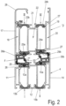
- eine Schnittdarstellung eines Flügel- und eines Blendrahmenprofils im geschlossenen Zustand des Flügels;
- Figur 3:
- eine Ausschnittsvergrößerung de Falzraumes der Anordnung aus
Fig. 2 ; - Figur 4:
- eine erste Dichtung eines Dichtungspaares aus
Fig. 2 und3 ; und - Figur 5:
- eine zweite Dichtung des Dichtungspaares aus
Fig. 2 und3 . -
Fig. 1 zeigt eine Tür 1, die einen schwenk- und/oder drehbaren Flügel mit einem Flügelrahmen 2 und einen Blendrahmen 3 aufweist, an dem der Flügel mit einem oder mehreren Beschlägen angelenkt ist. Alternativ zu Türen kann die vorliegende Erfindung auch bei Fenstern oder Fassadenelementen oder dgl. eingesetzt werden. - Der Blendrahmen 3 dieser Tür 1 weist Blendrahmenholme 4, 5 und 6 auf. Der Flügelrahmen 2 des Flügels weist einen vertikalen Flügelrahmenholm 7 auf der Griffseite sowie einen weiteren vertikalen Flügelrahmenholm 8 auf der Bandseite auf. Darüber hinaus weist der Flügelrahmen 2 ein oberen horizontalen Flügelrahmenholm 9 sowie einen unteren horizontalen Flügelrahmenholm 10 auf. Die Flügelrahmenholme 6, 7, 8 sind jeweils - hier durch Eckverbinder (hier nicht dargestellt) - zu dem Flügelrahmen 2 zusammengefügt, so dass in den Flügelrahmen 2 eine Füllung, wie z.B. eine Verglasung eingesetzt werden kann (hier nicht dargestellt).
- In
Fig. 2 sind ein Blendrahmenholm 4 und ein Flügelrahmenholm 5 der Tür 1 im Schnitt dargestellt. Zwischen dem Blendrahmenholm 4 und dem Flügelrahmenholm 5 ist ein Falzraum F nach Art eines Spaltes ausgebildet. Dieser Spalt soll dichtend überbrückt werden. - Der Blendrahmenholm 4 weist ein erstes Metallprofil 11 - ein erstes Außenprofil - auf, das mit einem metallischen Mittelprofil 12 über wenigstens einen oder mehrere erste Isolierstege (hier parallel ausgerichtet) 13a, 13b verbunden ist. Diese Isolierstege 13a, b zwischen dem ersten metallische Außenprofil und dem metallischen Mittelprofil 12 bilden eine erste Isolierstegzone I bzw. -ebene im Blendrahmenholm 10 aus. Ein zweites Metallprofil 14, ein weiteres Außenprofil - ist mit dem metallischen Mittelprofil 12 ebenfalls über wenigstens einen oder mehrere zweite (hier parallele) Isolierstege 15a, b verbunden. Die Isolierstege 15a, b zwischen dem zweiten Metallprofil 14 und dem Mittelprofil 12 bilden eine zweite Isolierstegzone II bzw. -ebene im Blendrahmenholm 10 aus. Die Metallprofile des Blendrahmenholms 4 weisen Hohlkammern auf, was für die Wärmedämmung vorteilhaft ist
- In
Fig. 2 weisen - beispielhaft - beide Isolierstegzonen I, II am Blendrahmenholm solche Isolierstege 13a, b; 15a, b auf, deren jeweiligen Endabschnitte form- und kraftschlüssig mit einer zugehörigen Nut der Metallprofile verbunden sind. - Die weiteren Blendrahmenholme 5, 6 der Tür oder des Fensters sind vorzugsweise genau wie der beschriebene Blendrahmenholm 4 aufgebaut.
- Der Flügelrahmenholm 7 weist ein erstes Metallprofil 17 als Außenprofil auf. In diesem ist hier wenigstens eine Hohlkammer 18 ausgebildet ist. Er weist ferner ein zweites metallisches Außenprofil 19 auf, in dem ebenfalls vorzugsweise wenigstens eine Hohlkammer 20 ausgebildet ist. Zwischen den beiden Metallprofilen 17 und 19 ist ein drittes Metallprofil, ein Mittelprofil 21, angeordnet, in dem ebenfalls vorzugsweise wenigstens eine Hohlkammer 22 ausgebildet ist. Auch diese Metallprofile 17, 19, 21 können alternativ ohne Hohlkammern ausgeführt sein oder jeweils mehrere Hohlkammern aufweisen. Die Hohlkammern verringern ggf. den Wärmedurchgang zwischen den an die Tür oder das Fenster oder das Fassadenelement angrenzenden Räumen und erlauben einfach das Anordnen von Eckverbindern oder dgl..
- Das erste Metallprofil 17 ist wiederum mit dem metallischen Mittelprofil 21 über wenigstens einen oder mehrere erste Isolierstege (hier parallel ausgerichtet) 23a, b verbunden. Diese Isolierstege 23a, b zwischen dem ersten metallische Außenprofil 17 und dem metallischen Mittelprofil 21 bilden eine erste Isolierstegzone III bzw. - ebene im Flügelrahmenholm 7. Das zweite metallische Außenprofil 19 ist mit dem metallischen Mittelprofil 21 ebenfalls über wenigstens einen oder mehrere zweite (hier parallele) Isolierstege 24a, b verbunden. Die Isolierstege 24a, b zwischen dem zweiten metallischen Außenprofil 19 und dem metallischen Mittelprofil 21 bilden eine zweite Isolierstegzone IV bzw. -ebene im Flügelrahmenholm 7 aus.
- In
Fig. 2 weist die Isolierstegzone III des Flügelrahmenprofilholms 7 die Isolierstege 23a, b auf, deren jeweiligen Endabschnitte 25 form- und kraftschlüssig jeweils mit einer Nut 26 des angrenzenden Metallprofils (Außenprofil oder Mittelprofil) verbunden sind, so dass sich jeweils eine insbesondere auch in z-Richtung (vgl. Koordinatensystem in Fig. ) bzw. in einer Richtung orthogonal zur Querschnittsebene des Verbundprofils 4 schubfeste Verbindung zwischen den Isolierstegen und dem angrenzenden Metallprofil ergibt. Diese Verbindung wird nachfolgend auch als schubfeste Verbindung bezeichnet. Sie bietet eine Schubfestigkeit gegen die infolge von Dilatation an einem Fenster oder einer Tür oder dgl. auftretenden Kräfte. - In
Fig. 2 ist gezeigt, dass die Isolierstege 24a, b der zweiten Isolierstegzone IV des Flügelrahmenholms 7 zwischen dem zweiten metallischen Außenprofil und dem metallischen Mittelprofil 21 eine Trennzone zwischen den Isolierstegen und dem zweiten 19 Außenprofil ausbilden, in welcher eine schublose Gleitführung eine Relativbewegung erlaubt. Alternativ kann die Trennzone auch zwischen den Isolierstegen 23a, b und dem anderen Metzallprofil bzw. Außenprofil und dem Mittelprofil 21 ausgebildet sein. Die Isolierstege 24a, b sind dazu in y- und x-Richtung (bezogen auf das Koordinatensystem inFig. 2 ) formschlüssig durch eine Kederverbindung 27mit dem zweiten metallischen Außenprofil verbunden. Derart wird eine Gleitführung gebildet. Die Schubfestigkeit in der Gleitführung orthogonal zur Querschnittsebene des Verbundprofils kann, muss aber nicht gegen Null gehen. Eine solche Gleitführung wird umgangssprachlich als "schublose Verbindung" bezeichnet. - Die Anordnung der schublosen Verbindung -hier in der Isolierstegebene IV- ist beispielhaft zu verstehen. Alternativ kann die schublose Verbindung auch in der Isolierstegebene III oder in beiden Isolierstegebene III, IV angeordnet sein oder auf andere Weise ausgebildet sein. Es kann auch auf eine schublose Verbindung verzichtet werden, wenn das Problem des Dilatationsausgleichs auf andere Weise oder nicht gelöst wird.
- Das Flügelrahmenprofil weist ferner eine Halteleiste 28 auf, durch welche die Füllung, wie z.B. eine Verglasung gehalten wird.
- Die Isolierstegebenen I und II des Blendrahmenprofils und die Isolierstegebenen III und IV des Flügelrahmenprofils entsprechen einander.
- Im Spalt bzw. im Falzraum F zwischen dem Blendrahmenholm und dem Flügelrahmenholm ist ferner ein vorteilhaftes Dichtungssystem angeordnet, um den Spalt des Falzraumes F abzudichten.
-
Figur 3 zeigt eine vergrößerte Darstellung des Falzraums F und der an den Falzraum angrenzenden Isolierzonen des Verbundprofilsystems ausFig. 2 . - Das Dichtungssystem im Falzraum F zwischen dem Flügelrahmenholm 7 und dem Blendrahmenholm 4 weist zwei Dichtungspaare auf, die jeweils aus zwei Dichtungen 29a, 30a bzw. 29b, 30b bestehen, von den jeweils die eine der beiden Dichtungen am Blendrahmenholm 4 und die andere Dichtung am Flügelrahmenholm 7 angeordnet ist. In jeder der beiden Isolierzonen I und II bzw. III und IV liegt jeweils eines der Dichtungspaare mit jeweils zwei verschiedenen Dichtungen 29a, 30a und 29b, 30b.
- Die beiden Dichtungspaare sind gleich aufgebaut, weisen aber jeweils zwei unterschiedliche Dichtungen 29a bzw. 29b und 30a bzw. 30b auf. Die Dichtungspaare sind derart zwar an sich jeweils gleich ausgebildet. Ihre Anordnung im Falzraum ist aber verschieden.
- Am ersten Dichtungspaar in der ersten bzw. dritten Isolierzone I, III ist die erste Dichtung 29a - die nachfolgend als Dichtungsanschlag bezeichnet wird - an dem Blendrahmenholm 4 - und die zweite Dichtung 30a - die nachfolgend als Lippendichtung bezeichnet wird - an dem Flügelrahmenholm 7 angeordnet. Dagegen ist am zweiten Dichtungspaar die erste Dichtung - der Dichtungsanschlag - 29b an dem Flügelrahmenholm 7 angeordnet und die als Lippendichtung bezeichnete zweite Dichtung 30b an dem Blendrahmenholm 4.
- Die ist vorteilhaft, da zum Ausbilden von zwei Dichtungspaaren mit je zwei verschiedenen Dichtungen doch insgesamt nur zwei verschiedene Bauarten von Dichtungen benötigt werden, was die Herstellung und Handhabung vereinfacht.
- Jedes Dichtungspaar bildet gemeinsam zwischen sich eine im geschlossenen Zustand des Flügels mit einem Steg 59 des Flügelrahmenholms oder des Blendrahmenholms nahezu rundum geschlossene Dichtkammer 34a, b aus. Zudem wird weiter vorteilhaft auch zischen den Dichtungspaaren eine weitere Dichtkammer 35 gebildet. Derart sind im Falzraum drei senkrecht zur Tür- oder Fenster(haupt)ebene aneinander grenzende Dichtkammern 34a, 35, 34b ausgebildet.
- Mit Hilfe der Dichtungspaare sind vier Anschlagbereiche A1, A2, A3, A4 im Falzraum ausgebildet, welche den Spalt unterbrechen, den der Falzraum ansonsten zwischen dem Blend- und dem Flügelrahmenholm im geschlossenen Zustand des Flügels ausbilden würde.
- Die zwei äußeren Anschlagbereiche A1, A4 sind jeweils zwischen einem Metallprofil des Blendrahmenholms 4 bzw. des Flügelrahmenholms 7 und jeweils einer der Dichtungen 30a, 30b ausgebildet. Die zwei weiteren (mittleren) Anschlagbereich A2, A3 sind dagegen direkt zwischen den beiden Dichtungen 29a, 30a bzw. 29b, 30b jedes Dichtungspaares ausgebildet. Diese vier Anschlagbereiche A1 - A4 sichern eine hervorragende Reduzierung des Wärmedurchgangs gegenüber bekannten Lösungen.
- Derart wird vorteilhaft wird im geschlossenen Zustand des Flügels im Falzraum F zwischen den beiden Räumen, welchen die Tür oder das Fenster voneinander trennt, wenigstens vierfach ein direktes Durchströmen von Luft verhindert. Der Wärmedurchgang im Falzraum kann damit weitgehend minimiert werden. Zudem wird auch die Schallübertragung durch den Falzraum F verringert.
-
Figur 4 zeigt die erste Dichtung 29a oder b des einen Dichtungspaars. Diese Dichtung wird nachfolgend auch als Dichtungsanschlag bezeichnet. Der Dichtungsanschlag weist einen Basissteg 38, vorzugsweise einen daran angeformten Haltefuß 36 und einen sich winklig in einem Winkel größer 60°, insbesondere in einem Winkel von 90° zum Basissteg 35 erstreckenden Anschlagsteg 37 auf. Der Basissteg 38 weist hier zwei Bereiche verschiedener Dicke beidseits des Anschlagstegs 37 auf. Der Haltefuß 36 ist zum rastenden Eingriff in eine zum Falzraum F gerichtete Nut 39 in dem jeweils zugeordneten Isoliersteg 13a, 24a ausgebildet.Figur 5 zeigt die zweite Dichtung 30a, b der beiden Dichtungspaare, die eine Lippendichtung ausbildet. Die als Lippendichtung ausgebildete Dichtung 30a, b weist einen Basisabschnitt 40 und zwei sich hierzu winklig, insbesondere im Wesentlichen senkrecht, erstreckende Dichtlippen 41 und 42 auf. Die Dichtlippe 41 bildet (im Zusammenspiel mit dem Anschlagsteg 37 der jeweils anderen Dichtung 29a, b) einen Teil eines Mitteldichtungsbereichs 50 aus, während die weitere Dichtlippe 42 an ihrem Ende als rechtwinklig dazu ausgerichteter Anschlagdichtungsbereich 51 (hier mit einer kleinen Hohlkammer 52) ausgebildet ist. - Die als Lippendichtung ausgebildete Dichtung 30a, b weist zudem eine oder vorzugsweise in ihrem Basisabschnitt 40 eine oder (hier) zwei oder mehrere Hohlkammern 43, 44 auf. Diese verbessern die Wärmedämmung. Der Basisabschnitt weist einen Basissteg 45 auf, der mit einem Befestigungsmittel (vorzugsweise einem Dichtungsfuß 46 zum Einrasten in eine korrespondierende Nut 47 eines Isolierstegs) zum Befestigen mit einer Nut-Federverbindung an einem der Isolierstege 22, 23 ausgebildet ist. Rechtwinklig zum Basissteg 45 erstrecken sich zwei Seitenstege 48a, 48b, welche an ihren Enden in die Dichtlippen 41, 42 übergehen. Zwischen den Enden der Seitenstege 48a, 48b erstreckt sich ferner ein Stützsteg 48c in einem spitzen Winkel α zum Basissteg 45. Hierdurch wird der Seitensteg 48a bzw. in der Verlängerung die Dichtlippe 41sicher abgestützt, und zwar vorzugsweise an einem Profilanschlagsteg 55, 56.
- Der Anschlagdichtungsbereich 51 ist über einen Verbindungsstegabschnitt 49 mit dem Basisabschnitt 40 (beabstandet) verbunden. Dies erleichtert die Montage. Der Anschlagsdichtungsbereich 51 weist hier vorteilhaft weist ein Befestigungsmittel auf, mit dem er mit einer Nut-Federverbindung an dem zugehörigen Profilanschlagsteg entweder des Flügelrahmenholms 7 oder des Blendrahmenholms 4 verrastet ist. Vorzugsweise ist das Befestigungsmittel ein Fuß 53, mit dem er in einer Nut 54 des Profilanschlagsteges 55, 56 befestigt ist
- Der Anschlagsdichtungsbereich 51 des einen der beiden Dichtungspaare überbrückt dichtend den Spalt zwischen dem freien Ende des Profilanschlagssteg 55 des Blendrahmenholms 4 und der gegenüberliegenden Ecke des Flügelrahmenholms 7, während der andere Anschlagsdichtungsbereich den Spalt zwischen dem feien Ende des Profilanschlagsstegs 56 des Flügelrahmenholms 7 und der gegenüberliegenden Ecke des Blendrahmenholms 4 dichtend schließt.
- In etwa jeweils auf Höhe der Isolierzonenmitten der Isolierzonen I, II bzw. II, IV bilden die beiden Dichtungen 29a, 30a bzw. 29b, 30b jedes Dichtungspaares jeweils zusammen eine Mitteldichtung aus. Jede dieser beiden Mitteldichtungen besteht aus einer der Anschlagsdichtlippen 41 der jeweils zweiten Dichtung 30a, b (die Lippendichtung) und einem der Anschlagstege 37 der jeweils ersten Dichtung 29a, b (der Anschlagdichtung). Im Außenbereich des Falzraumes an den Profilholmen liegt jeweils pro Dichtungspaar dichtend einer der beiden Anschlagdichtungsbereiche 51. Abschließend seien noch einige weitere vorteilhafte Details der Anordnung des Dichtungspaares oder hier der Dichtungspaare am Blend- bzw. Flügelrahmenholm 4, 7 betrachtet.
- Wie in
Fig. 3 zu erkennen, ist der Basissteg 38 vorzugsweise der Anschlagdichtung jeweils derart bemessen, dass er im eingebauten Zustand genau in eine nicht hinterschnittene Nut 57, 58 am Blend- oder Flügelrahmenprofil einpasst. Derart sitzt diese Dichtung 29a, b jeweils gut und sicher am Blend- oder Flügelrahmenprofil. - Einen entsprechend guten Sitz sichern an der Lippendichtung jeweils die zwei Befestigungsmittel, hier die Haltefüße 46 und 53 sowie die Nuten 47 im Isoliersteg 15a, 23a und die Füße 53 in den Nuten 54 der Profilanschlagstege 55, 56 im Zusammenspiel mit dem schräg dazwischen verlaufenden Stützsteg. Derart sitzt auch die Dichtung 30a, b jeweils gut und sicher am Blend- oder Flügelrahmenprofil.
- Die weiteren Blend- und Flügelrahmenholme 5, 6 bzw. 8, 9, 10 sind bevorzugt - aber nicht zwingend - wie die beschriebenen Blend- und Flügelrahmenholme 4, 7 der
Fig. 2 und3 nebst Dichtungssystem, mit den Dichtungen derFig. 4 , aufgebaut. -
Bezugszeichen Isolierstegzone I, II, II, IV Tür 1 Flügelrahmen 2 Blendrahmen 3 Blendrahmenholme 4, 5, 6 Flügelrahmenholme 7, 8, 9, 10 Metallprofil 11 Mittelprofil 12 Isolierstege 13a, 13b Metallprofil 14 Isolierstege 15a, b Nut 16 Metallprofil 17 Hohlkammer 18 Außenprofil 19 Hohlkammer 20 Mittelprofil 21 Hohlkammer 22 Isolierstege 23a, b; 24a, b Endabschnitte 25 Nut 26 Kederverbindung 27 Halteleiste 28 Dichtungen 29a, 30a und 29b, 30b Anschlagsdichtlippe 31 Anschlagsteg 32 Anschlagdichtung 33 Dichtkammer 34a, b Dichtkammer 35 Haltefuß 36 Anschlagsteg 37 Basissteg 38 Nut 39 Basisabschnitt 40 Dichtlippen 41 und 42 Hohlkammern 43, 44 Basissteg 45 Dichtungsfuß 46 Nut 47 Seitenstege 48a, 48b Stützsteg 48c Verbindungsteg 49 Mitteldichtungsbereich 50 Anschlagdichtungsbereich 51 Hohlkammer 52 Fuß 53 Nut 54 Profilanschlagssteg 55, 56 Nut 57, 58 Steg 59
Claims (19)
- Tür (1), Fenster oder Fassadenelement mit einem Flügel mit einem aus Flügelrahmenholmen (7-10) zusammengesetzten Flügelrahmen (2) und mit einem aus Blendrahmenholmen (4, 5, 6) zusammengesetzten Blendrahmen (3), an dem der Flügel angelenkt ist, wobei ein wenigstens zwei Dichtungen aufweisenden Dichtungssystem für einen im geschlossenen Zustand zwischen dem Blend- und dem Flügelrahmen ausgebildeten Falzraum (F) vorgesehen ist, wobei das Dichtungssystem wenigstens ein oder zwei Dichtungspaare aufweist, die jeweils aus einer ersten Dichtung (29a, 30b) am Blendrahmenholm (4, 5, 6) und einer zweiten Dichtung (29b, 30a) am Flügelrahmenholm (7, 8, 9, 10) bestehen, die gemeinsam jeweils wenigstens eine oder vorzugsweise zwei oder mehr Mitteldichtung(en) ausbilden, welche den Falzraum (F) im geschlossenen Zustand des Flügels dichtend überbrückt/überbrücken, wobei der Blendrahmen und der Flügelrahmen aus den Blendrahmenholmen (4, 5, 6) und den Flügelrahmenholmen (7-10) mit zwei Metallprofilen besteht, die über einen oder mehrere Isoliersteg(e) voneinander getrennt sind, die eine Isolierzone (I, III) ausbilden, wobei jede der beiden Dichtungen (29a, 30a; 29b, 30b) des wenigstens einen Dichtungspaares mit wenigstens einer Nut-Federverbindung an jeweils einem der Isolierstege des Blendrahmenholms oder des Flügelrahmenholmes (4-10) festgelegt ist, wobeia. die eine der beiden Dichtungen des oder jedes Dichtungspaars als Dichtungsanschlag ausgebildet ist, der einen Basissteg (38) aufweist und einen sich winklig in einem Winkel größer 60° zum Basissteg (38) erstreckenden Anschlagsteg (37) undb. die zweite Dichtung (30a, b) des oder jedes Dichtungspaares als Lippendichtung ausgebildet ist, die einen Basisabschnitt (40) aufweist,dadurch gekennzeichnet, dass die zweite Dichtung (30a,b) zwei sich winklig, insbesondere im Wesentlichen senkrecht, zu dem Basisabschnitt (40) erstreckende Dichtlippen (41 und 42) aufweist.
- Tür (1), Fenster oder Fassadenelement nach Anspruch 1, dadurch gekennzeichnet, dass der Blendrahmen und/oder der Flügelrahmen aus Blendrahmenholmen (4-6) und/oder Flügelrahmenholmen (7-10) aus drei Metallprofilen besteht, die jeweils über einen oder mehrere Isoliersteg (e) (13a,b; 15a,b; 23a, b; 24a,b) voneinander getrennt sind, die jeweils Isolierzonen (I, III; II, IV) ausbilden.
- Tür (1), Fenster oder Fassadenelement nach einem der vorstehenden Ansprüche, dadurch gekennzeichnet, dass das Dichtungssystem im Falzraum F zwischen dem Flügelrahmenholm und dem Blendrahmenholm (4-10) zwei der Dichtungspaare aufweist, die jeweils aus zwei Dichtungen (29a, 29b bzw. 30a, 30b) bestehen, von den jeweils die eine der beiden Dichtungen am Blendrahmenholm (4, 5, 6) und die andere Dichtung am Flügelrahmenholm (7, 8, 9, 10) angeordnet ist.
- Tür (1), Fenster oder Fassadenelement nach Anspruch 3, dadurch gekennzeichnet, dass zwei der Dichtungspaare vorgesehen sind, die jeweils gleich ausgebildet sind aber im Falzraum unterschiedlich angeordnet sind.
- Tür (1), Fenster oder Fassadenelement nach Anspruch 4, dadurch gekennzeichnet, dass die zwei Dichtungspaare gleich ausgebildet sind, aber jeweils zwei voneinander unterschiedliche Dichtungen (29a bzw. 29b und 30a bzw. 30b) aufweisen.
- Tür (1), Fenster oder Fassadenelement nach einem der vorstehenden Ansprüche 3 bis 5, dadurch gekennzeichnet, dass die eine der beiden Dichtungen des wenigstens einen Dichtungspaares an dem Blendrahmenholm (4) angeordnet ist und die zweite Dichtung (30a) dieses Dichtungspaares an dem Flügelrahmenholm.
- Tür (1), Fenster oder Fassadenelement nach einem der vorstehenden Ansprüche 3 bis 6, dadurch gekennzeichnet, dass bei einer Anordnung von zwei der Dichtungspaare im Falzraum (F) am ersten Dichtungspaar die erste Dichtung (29a) - ein Dichtungsanschlag - an dem Blendrahmenholm (4) angeordnet ist und die zweite Dichtung (30a) - eine Lippendichtung - an dem Flügelrahmenholm und das am zweiten Dichtungspaar die erste Dichtung - der Dichtungsanschlag - (29b) an dem Flügelrahmenholm (7) angeordnet ist und die als Lippendichtung bezeichnete zweite Dichtung (30b) an dem Blendrahmenholm (4).
- Tür (1), Fenster oder Fassadenelement nach einem der vorstehenden Ansprüche, dadurch gekennzeichnet, dass jedes Dichtungspaar im geschlossenen Zustand des Flügels mit einem Steg (59) des Blend- oder Flügelrahmenholms jeweils eine rundum geschlossene Dichtkammer (34a, b) ausbildet und/oder dass zwischen den beiden Dichtungspaaren im geschlossenen Zustand des Flügels mit dem Blend- und dem Flügelrahmen im Falzraum eine rundum geschlossene Dichtkammer (35) ausgebildet wird.
- Tür (1), Fenster oder Fassadenelement nach einem der vorstehenden Ansprüche, dadurch gekennzeichnet, dass im Falzraum (F) drei senkrecht zur Tür- oder Fenster(haupt)ebene aneinander grenzende Dichtkammern (34a, 35, 34b) ausgebildet sind und/oder dass im Falzraum (F) im geschlossenen Zustand des Flügels vier Dicht-Anschlagbereiche (A1, A2, A3, A4) zwischen dem Flügelrahmenholm und dem Blendrahmenholm ausgebildet sind.
- Tür (1), Fenster oder Fassadenelement nach einem der vorstehenden Ansprüche, dadurch gekennzeichnet, dass sich der Anschlagsteg (37) winklig in einem Winkel von 90° zum Basissteg (35) erstreckt.
- Tür (1), Fenster oder Fassadenelement nach einem der vorstehenden Ansprüche, dadurch gekennzeichnet, dass der Dichtungsanschlag einen Haltefuß (36) aufweist.
- Tür (1), Fenster oder Fassadenelement nach einem der vorstehenden Ansprüche, dadurch gekennzeichnet, dass sich die Dichtlippen (41, 42) senkrecht zum Basisabschnitt (40) erstreckenden.
- Tür (1), Fenster oder Fassadenelement nach einem der vorstehenden Ansprüche, dadurch gekennzeichnet, dass eine der Dichtlippen (41) der Lippendichtung im geschlossenen Zustand des Flügels im Zusammenspiel mit dem Anschlagsteg (37) des zugehörigen Dichtungsanschlags jeweils eine den Falzraum überbrückende Mitteldichtung ausbildet.
- Tür (1), Fenster oder Fassadenelement nach einem der vorstehenden Ansprüche, dadurch gekennzeichnet, dass die weitere Dichtlippe (42) der jeweils zweiten Dichtung (30a, b) - die Lippendichtung - des wenigstens einen Dichtungspaares an ihrem Ende als rechtwinklig dazu ausgerichteter Anschlagdichtungsbereich (51) ausgebildet ist.
- Tür (1), Fenster oder Fassadenelement nach einem der vorstehenden Ansprüche, dadurch gekennzeichnet, dass im Anschlagdichtungsbereich (51) eine Hohlkammer (52) ausgebildet ist.
- Tür (1), Fenster oder Fassadenelement nach einem der vorstehenden Ansprüche, dadurch gekennzeichnet, dass die als Lippendichtung ausgebildete Dichtung (30a, b) in ihrem Basisabschnitt (40) eine oder mehrere Hohlkammern (43, 44) aufweist und/oder dass die als Lippendichtung ausgebildete Dichtung (30a, b) in ihrem Basisabschnitt (40) ein Befestigungsmittel zum Befestigen am zugeordneten Blend- oder Flügelrahmenholm aufweist und ein weiteres Befestigungsmittel zum Befestigen am zugeordneten Blend- oder Flügelrahmenholm in ihrem Anschlagsdichtungsbereich (51).
- Tür (1), Fenster oder Fassadenelement nach einem der vorstehenden Ansprüche, dadurch gekennzeichnet, dass der Basisabschnitt (40) einen Basissteg (45) zur Anlage am Blend- oder Flügelrahmenholm aufweist sowie zwei sich winklig, vorzugsweise rechtwinklig, zum Basisabschnitt erstreckende Seitenstege (46, 47), die an ihren Enden in die Dichtlippen (41, 42) übergehen und dass sich zwischen den Enden der Seitenstege (48a, 48b) ferner ein Stützsteg (48c) erstreckt, wobei sich der Stützsteg (48c) vorzugsweise in einem spitzen Winkel 1° < α < 45 ° zum Basissteg (45) erstreckt.
- Tür (1), Fenster oder Fassadenelement nach einem der vorstehenden Ansprüche, dadurch gekennzeichnet, dass der Anschlagdichtungsbereich (51) über einen Verbindungsstegabschnitt (49) mit dem Basisabschnitt (40) verbunden ist.
- Tür (1), Fenster oder Fassadenelement nach einem der vorstehenden Ansprüche 3 - 7, dadurch gekennzeichnet, dass der Anschlagdichtungsbereich (51) der Lippendichtung des einen der beiden Dichtungspaare dichtend den Spalt zwischen dem freien Ende des Profilanschlagsstegs (55) des Blendrahmenholms (4, 5, 6) und der gegenüberliegenden Ecke des Flügelrahmenholms /-10) überbrückt, während der andere Anschlagsdichtungsbereich(51) der zweiten Lippendichtung des zweiten Dichtungspaares den Spalt zwischen dem feien Ende des Profilanschlagsstegs (56) des Flügelrahmenholms und der gegenüberliegenden Ecke des Blendrahmenholms dichtend schließt und/oder dass mindestens eine Dichtung des einen Dichtungspaars oder der Dichtungspaare eine oder mehrere Hohlkammern auf.
Applications Claiming Priority (3)
| Application Number | Priority Date | Filing Date | Title |
|---|---|---|---|
| DE102014106226.4A DE102014106226A1 (de) | 2014-05-05 | 2014-05-05 | Verbundprofil für Türen, Fenster oder Fassadenelemente |
| DE102014112112.0A DE102014112112A1 (de) | 2014-08-25 | 2014-08-25 | Tür, Fenster oder Fassadenelement mit einem Dichtungsystem |
| PCT/EP2015/059387 WO2015169669A1 (de) | 2014-05-05 | 2015-04-29 | Tür, fenster oder fassadenelement mit einem dichtungssystem |
Publications (2)
| Publication Number | Publication Date |
|---|---|
| EP3140486A1 EP3140486A1 (de) | 2017-03-15 |
| EP3140486B1 true EP3140486B1 (de) | 2023-04-19 |
Family
ID=53175005
Family Applications (1)
| Application Number | Title | Priority Date | Filing Date |
|---|---|---|---|
| EP15721641.7A Active EP3140486B1 (de) | 2014-05-05 | 2015-04-29 | Tür, fenster oder fassadenelement mit einem dichtungssystem |
Country Status (5)
| Country | Link |
|---|---|
| EP (1) | EP3140486B1 (de) |
| CN (2) | CN106460445B (de) |
| PL (1) | PL3140486T3 (de) |
| RU (1) | RU2698188C2 (de) |
| WO (1) | WO2015169669A1 (de) |
Families Citing this family (1)
| Publication number | Priority date | Publication date | Assignee | Title |
|---|---|---|---|---|
| SG10201908317PA (en) * | 2019-09-09 | 2021-04-29 | Tacam Steel Pte Ltd | Sealing assembly for acoustic doors and method of installing the same |
Citations (1)
| Publication number | Priority date | Publication date | Assignee | Title |
|---|---|---|---|---|
| DE102012111005A1 (de) * | 2012-11-15 | 2014-05-15 | Heroal - Johann Henkenjohann Gmbh & Co. Kg | Tür, insbesondere Aluminium-Haustür, und Türprofilsystem |
Family Cites Families (6)
| Publication number | Priority date | Publication date | Assignee | Title |
|---|---|---|---|---|
| DE8202323U1 (de) * | 1982-01-30 | 1983-04-21 | Fa. Eduard Hueck, 5880 Lüdenscheid | Waermegedaemmter rahmen fuer fenster, tueren, fassadenkonstruktionen u. dergleichen |
| DE3343687A1 (de) * | 1983-11-30 | 1985-06-05 | Schweizerische Aluminium Ag, Chippis | Metall-rahmenkonstruktion fuer fenster oder tueren |
| DE3509466A1 (de) * | 1985-02-11 | 1986-08-14 | Josef Gartner & Co, 8883 Gundelfingen | Fassadenkonstruktion |
| DE4342525A1 (de) * | 1993-12-15 | 1995-06-22 | Guenter Werner | Glasfassade mit Fenster |
| DE9400144U1 (de) * | 1994-01-07 | 1994-02-24 | E.M.B. Metallbau und Brandschutztechnik GmbH, 46446 Emmerich | Aufsatzkörper für Dachöffnungen |
| DE19820434C2 (de) * | 1998-05-07 | 2002-10-31 | Ingbuero Dr Ing Harald Schulz | Parallel-Ausstellfenster-Anordnung mit Dichtsystem |
-
2015
- 2015-04-29 RU RU2016144341A patent/RU2698188C2/ru not_active IP Right Cessation
- 2015-04-29 WO PCT/EP2015/059387 patent/WO2015169669A1/de not_active Ceased
- 2015-04-29 CN CN201580023419.1A patent/CN106460445B/zh active Active
- 2015-04-29 EP EP15721641.7A patent/EP3140486B1/de active Active
- 2015-04-29 PL PL15721641.7T patent/PL3140486T3/pl unknown
- 2015-04-29 CN CN202010063597.XA patent/CN111255339A/zh active Pending
Patent Citations (1)
| Publication number | Priority date | Publication date | Assignee | Title |
|---|---|---|---|---|
| DE102012111005A1 (de) * | 2012-11-15 | 2014-05-15 | Heroal - Johann Henkenjohann Gmbh & Co. Kg | Tür, insbesondere Aluminium-Haustür, und Türprofilsystem |
Also Published As
| Publication number | Publication date |
|---|---|
| RU2698188C2 (ru) | 2019-08-22 |
| RU2016144341A (ru) | 2018-06-05 |
| PL3140486T3 (pl) | 2023-08-21 |
| CN106460445B (zh) | 2021-02-02 |
| CN106460445A (zh) | 2017-02-22 |
| CN111255339A (zh) | 2020-06-09 |
| RU2016144341A3 (de) | 2018-10-23 |
| EP3140486A1 (de) | 2017-03-15 |
| WO2015169669A1 (de) | 2015-11-12 |
Similar Documents
| Publication | Publication Date | Title |
|---|---|---|
| EP1987220B1 (de) | Gerahmtes flächentragelement sowie rahmenprofil für ein derartiges gerahmtes flächentragelement | |
| DE202010008921U1 (de) | Mitteldichtung für hoch wärmegedämmte Fenster oder Türen | |
| DE2920445A1 (de) | Verschlussanordnung mit verglasung | |
| AT523544B1 (de) | Kunststoff-Metall-Fenstersystem | |
| EP2363567B1 (de) | Rahmen eines Kunststofffensters oder einer Kunststofftür | |
| EP3438395B1 (de) | Fensterrahmensystem | |
| EP1965011A2 (de) | Fensterprofil | |
| EP0191190B1 (de) | Fenster oder Tür bzw. Festverglasung mit einer schusssicheren Scheibe | |
| EP3190240B1 (de) | Dichtungselement | |
| DE19525957C2 (de) | Warmfassade | |
| EP3680438B1 (de) | Anordnung aus einem rahmenprofil und einem dichtprofil für einen fenster- oder türrahmen | |
| EP1744003A2 (de) | Flügel mit Falzgrunddichtung | |
| WO2015169669A1 (de) | Tür, fenster oder fassadenelement mit einem dichtungssystem | |
| DE102014112112A1 (de) | Tür, Fenster oder Fassadenelement mit einem Dichtungsystem | |
| EP3140484B1 (de) | Verbundprofil für türen, fenster oder fassadenelemente | |
| EP2487313A1 (de) | Rahmenkonstruktion für ein Fenster oder eine Tür | |
| DE102016125334A1 (de) | Fenster oder Tür mit einer Dichtungsanordnung und Falzdichtung | |
| DE2934940A1 (de) | Doppelfenster | |
| EP3299567B1 (de) | Holmanordnung für einen gebäudeverschluss, verfahren zum herstellen einer holmanordnung sowie gebäudeverschluss | |
| EP2942467B1 (de) | Tür mit einem griffprofil | |
| DE102014112145A1 (de) | Verbundprofil für Türen, Fenster oder Fassadenelemente | |
| EP3045648B1 (de) | Schwing-wendefenster mit einer dichtungsanordnung | |
| EP3342971B1 (de) | Fenster oder tür mit einem flügelrahmen mit einem glasträger | |
| DE19643681A1 (de) | Verbundprofilelement mit zumindest einem Metall-Profilstab und zumindest einem Kunststoff-Profilabschnitt | |
| EP1529892A2 (de) | Dichtung für eine Pfosten/Riegel-Konstruktion |
Legal Events
| Date | Code | Title | Description |
|---|---|---|---|
| STAA | Information on the status of an ep patent application or granted ep patent |
Free format text: STATUS: THE INTERNATIONAL PUBLICATION HAS BEEN MADE |
|
| PUAI | Public reference made under article 153(3) epc to a published international application that has entered the european phase |
Free format text: ORIGINAL CODE: 0009012 |
|
| STAA | Information on the status of an ep patent application or granted ep patent |
Free format text: STATUS: REQUEST FOR EXAMINATION WAS MADE |
|
| 17P | Request for examination filed |
Effective date: 20161129 |
|
| AK | Designated contracting states |
Kind code of ref document: A1 Designated state(s): AL AT BE BG CH CY CZ DE DK EE ES FI FR GB GR HR HU IE IS IT LI LT LU LV MC MK MT NL NO PL PT RO RS SE SI SK SM TR |
|
| AX | Request for extension of the european patent |
Extension state: BA ME |
|
| DAV | Request for validation of the european patent (deleted) | ||
| DAX | Request for extension of the european patent (deleted) | ||
| STAA | Information on the status of an ep patent application or granted ep patent |
Free format text: STATUS: EXAMINATION IS IN PROGRESS |
|
| 17Q | First examination report despatched |
Effective date: 20200722 |
|
| GRAP | Despatch of communication of intention to grant a patent |
Free format text: ORIGINAL CODE: EPIDOSNIGR1 |
|
| STAA | Information on the status of an ep patent application or granted ep patent |
Free format text: STATUS: GRANT OF PATENT IS INTENDED |
|
| INTG | Intention to grant announced |
Effective date: 20221028 |
|
| GRAS | Grant fee paid |
Free format text: ORIGINAL CODE: EPIDOSNIGR3 |
|
| GRAJ | Information related to disapproval of communication of intention to grant by the applicant or resumption of examination proceedings by the epo deleted |
Free format text: ORIGINAL CODE: EPIDOSDIGR1 |
|
| GRAL | Information related to payment of fee for publishing/printing deleted |
Free format text: ORIGINAL CODE: EPIDOSDIGR3 |
|
| STAA | Information on the status of an ep patent application or granted ep patent |
Free format text: STATUS: EXAMINATION IS IN PROGRESS |
|
| GRAP | Despatch of communication of intention to grant a patent |
Free format text: ORIGINAL CODE: EPIDOSNIGR1 |
|
| STAA | Information on the status of an ep patent application or granted ep patent |
Free format text: STATUS: GRANT OF PATENT IS INTENDED |
|
| INTC | Intention to grant announced (deleted) | ||
| GRAA | (expected) grant |
Free format text: ORIGINAL CODE: 0009210 |
|
| STAA | Information on the status of an ep patent application or granted ep patent |
Free format text: STATUS: THE PATENT HAS BEEN GRANTED |
|
| REG | Reference to a national code |
Ref country code: FR Ref legal event code: PLFP Year of fee payment: 9 |
|
| INTG | Intention to grant announced |
Effective date: 20230306 |
|
| AK | Designated contracting states |
Kind code of ref document: B1 Designated state(s): AL AT BE BG CH CY CZ DE DK EE ES FI FR GB GR HR HU IE IS IT LI LT LU LV MC MK MT NL NO PL PT RO RS SE SI SK SM TR |
|
| REG | Reference to a national code |
Ref country code: GB Ref legal event code: FG4D Free format text: NOT ENGLISH |
|
| REG | Reference to a national code |
Ref country code: DE Ref legal event code: R096 Ref document number: 502015016320 Country of ref document: DE |
|
| REG | Reference to a national code |
Ref country code: CH Ref legal event code: EP |
|
| REG | Reference to a national code |
Ref country code: IE Ref legal event code: FG4D Free format text: LANGUAGE OF EP DOCUMENT: GERMAN |
|
| REG | Reference to a national code |
Ref country code: AT Ref legal event code: REF Ref document number: 1561286 Country of ref document: AT Kind code of ref document: T Effective date: 20230515 |
|
| REG | Reference to a national code |
Ref country code: NL Ref legal event code: FP |
|
| REG | Reference to a national code |
Ref country code: LT Ref legal event code: MG9D |
|
| P01 | Opt-out of the competence of the unified patent court (upc) registered |
Effective date: 20230814 |
|
| PG25 | Lapsed in a contracting state [announced via postgrant information from national office to epo] |
Ref country code: SE Free format text: LAPSE BECAUSE OF FAILURE TO SUBMIT A TRANSLATION OF THE DESCRIPTION OR TO PAY THE FEE WITHIN THE PRESCRIBED TIME-LIMIT Effective date: 20230419 Ref country code: PT Free format text: LAPSE BECAUSE OF FAILURE TO SUBMIT A TRANSLATION OF THE DESCRIPTION OR TO PAY THE FEE WITHIN THE PRESCRIBED TIME-LIMIT Effective date: 20230821 Ref country code: NO Free format text: LAPSE BECAUSE OF FAILURE TO SUBMIT A TRANSLATION OF THE DESCRIPTION OR TO PAY THE FEE WITHIN THE PRESCRIBED TIME-LIMIT Effective date: 20230719 Ref country code: ES Free format text: LAPSE BECAUSE OF FAILURE TO SUBMIT A TRANSLATION OF THE DESCRIPTION OR TO PAY THE FEE WITHIN THE PRESCRIBED TIME-LIMIT Effective date: 20230419 |
|
| PG25 | Lapsed in a contracting state [announced via postgrant information from national office to epo] |
Ref country code: RS Free format text: LAPSE BECAUSE OF FAILURE TO SUBMIT A TRANSLATION OF THE DESCRIPTION OR TO PAY THE FEE WITHIN THE PRESCRIBED TIME-LIMIT Effective date: 20230419 Ref country code: LV Free format text: LAPSE BECAUSE OF FAILURE TO SUBMIT A TRANSLATION OF THE DESCRIPTION OR TO PAY THE FEE WITHIN THE PRESCRIBED TIME-LIMIT Effective date: 20230419 Ref country code: LT Free format text: LAPSE BECAUSE OF FAILURE TO SUBMIT A TRANSLATION OF THE DESCRIPTION OR TO PAY THE FEE WITHIN THE PRESCRIBED TIME-LIMIT Effective date: 20230419 Ref country code: IS Free format text: LAPSE BECAUSE OF FAILURE TO SUBMIT A TRANSLATION OF THE DESCRIPTION OR TO PAY THE FEE WITHIN THE PRESCRIBED TIME-LIMIT Effective date: 20230819 Ref country code: HR Free format text: LAPSE BECAUSE OF FAILURE TO SUBMIT A TRANSLATION OF THE DESCRIPTION OR TO PAY THE FEE WITHIN THE PRESCRIBED TIME-LIMIT Effective date: 20230419 Ref country code: GR Free format text: LAPSE BECAUSE OF FAILURE TO SUBMIT A TRANSLATION OF THE DESCRIPTION OR TO PAY THE FEE WITHIN THE PRESCRIBED TIME-LIMIT Effective date: 20230720 |
|
| PG25 | Lapsed in a contracting state [announced via postgrant information from national office to epo] |
Ref country code: LU Free format text: LAPSE BECAUSE OF NON-PAYMENT OF DUE FEES Effective date: 20230429 Ref country code: FI Free format text: LAPSE BECAUSE OF FAILURE TO SUBMIT A TRANSLATION OF THE DESCRIPTION OR TO PAY THE FEE WITHIN THE PRESCRIBED TIME-LIMIT Effective date: 20230419 |
|
| PG25 | Lapsed in a contracting state [announced via postgrant information from national office to epo] |
Ref country code: SK Free format text: LAPSE BECAUSE OF FAILURE TO SUBMIT A TRANSLATION OF THE DESCRIPTION OR TO PAY THE FEE WITHIN THE PRESCRIBED TIME-LIMIT Effective date: 20230419 |
|
| PG25 | Lapsed in a contracting state [announced via postgrant information from national office to epo] |
Ref country code: MC Free format text: LAPSE BECAUSE OF FAILURE TO SUBMIT A TRANSLATION OF THE DESCRIPTION OR TO PAY THE FEE WITHIN THE PRESCRIBED TIME-LIMIT Effective date: 20230419 |
|
| REG | Reference to a national code |
Ref country code: DE Ref legal event code: R097 Ref document number: 502015016320 Country of ref document: DE |
|
| PG25 | Lapsed in a contracting state [announced via postgrant information from national office to epo] |
Ref country code: SM Free format text: LAPSE BECAUSE OF FAILURE TO SUBMIT A TRANSLATION OF THE DESCRIPTION OR TO PAY THE FEE WITHIN THE PRESCRIBED TIME-LIMIT Effective date: 20230419 Ref country code: SK Free format text: LAPSE BECAUSE OF FAILURE TO SUBMIT A TRANSLATION OF THE DESCRIPTION OR TO PAY THE FEE WITHIN THE PRESCRIBED TIME-LIMIT Effective date: 20230419 Ref country code: RO Free format text: LAPSE BECAUSE OF FAILURE TO SUBMIT A TRANSLATION OF THE DESCRIPTION OR TO PAY THE FEE WITHIN THE PRESCRIBED TIME-LIMIT Effective date: 20230419 Ref country code: MC Free format text: LAPSE BECAUSE OF FAILURE TO SUBMIT A TRANSLATION OF THE DESCRIPTION OR TO PAY THE FEE WITHIN THE PRESCRIBED TIME-LIMIT Effective date: 20230419 Ref country code: EE Free format text: LAPSE BECAUSE OF FAILURE TO SUBMIT A TRANSLATION OF THE DESCRIPTION OR TO PAY THE FEE WITHIN THE PRESCRIBED TIME-LIMIT Effective date: 20230419 Ref country code: DK Free format text: LAPSE BECAUSE OF FAILURE TO SUBMIT A TRANSLATION OF THE DESCRIPTION OR TO PAY THE FEE WITHIN THE PRESCRIBED TIME-LIMIT Effective date: 20230419 Ref country code: CZ Free format text: LAPSE BECAUSE OF FAILURE TO SUBMIT A TRANSLATION OF THE DESCRIPTION OR TO PAY THE FEE WITHIN THE PRESCRIBED TIME-LIMIT Effective date: 20230419 |
|
| REG | Reference to a national code |
Ref country code: IE Ref legal event code: MM4A |
|
| PLBE | No opposition filed within time limit |
Free format text: ORIGINAL CODE: 0009261 |
|
| STAA | Information on the status of an ep patent application or granted ep patent |
Free format text: STATUS: NO OPPOSITION FILED WITHIN TIME LIMIT |
|
| 26N | No opposition filed |
Effective date: 20240122 |
|
| PG25 | Lapsed in a contracting state [announced via postgrant information from national office to epo] |
Ref country code: IE Free format text: LAPSE BECAUSE OF NON-PAYMENT OF DUE FEES Effective date: 20230429 |
|
| PG25 | Lapsed in a contracting state [announced via postgrant information from national office to epo] |
Ref country code: IE Free format text: LAPSE BECAUSE OF NON-PAYMENT OF DUE FEES Effective date: 20230429 |
|
| PG25 | Lapsed in a contracting state [announced via postgrant information from national office to epo] |
Ref country code: SI Free format text: LAPSE BECAUSE OF FAILURE TO SUBMIT A TRANSLATION OF THE DESCRIPTION OR TO PAY THE FEE WITHIN THE PRESCRIBED TIME-LIMIT Effective date: 20230419 |
|
| PG25 | Lapsed in a contracting state [announced via postgrant information from national office to epo] |
Ref country code: SI Free format text: LAPSE BECAUSE OF FAILURE TO SUBMIT A TRANSLATION OF THE DESCRIPTION OR TO PAY THE FEE WITHIN THE PRESCRIBED TIME-LIMIT Effective date: 20230419 |
|
| PG25 | Lapsed in a contracting state [announced via postgrant information from national office to epo] |
Ref country code: BG Free format text: LAPSE BECAUSE OF FAILURE TO SUBMIT A TRANSLATION OF THE DESCRIPTION OR TO PAY THE FEE WITHIN THE PRESCRIBED TIME-LIMIT Effective date: 20230419 |
|
| PG25 | Lapsed in a contracting state [announced via postgrant information from national office to epo] |
Ref country code: BG Free format text: LAPSE BECAUSE OF FAILURE TO SUBMIT A TRANSLATION OF THE DESCRIPTION OR TO PAY THE FEE WITHIN THE PRESCRIBED TIME-LIMIT Effective date: 20230419 |
|
| PGFP | Annual fee paid to national office [announced via postgrant information from national office to epo] |
Ref country code: PL Payment date: 20250314 Year of fee payment: 11 |
|
| PGFP | Annual fee paid to national office [announced via postgrant information from national office to epo] |
Ref country code: GB Payment date: 20250313 Year of fee payment: 11 |
|
| PGFP | Annual fee paid to national office [announced via postgrant information from national office to epo] |
Ref country code: NL Payment date: 20250425 Year of fee payment: 11 |
|
| PGFP | Annual fee paid to national office [announced via postgrant information from national office to epo] |
Ref country code: DE Payment date: 20250317 Year of fee payment: 11 |
|
| PGFP | Annual fee paid to national office [announced via postgrant information from national office to epo] |
Ref country code: BE Payment date: 20250422 Year of fee payment: 11 Ref country code: IT Payment date: 20250430 Year of fee payment: 11 |
|
| PGFP | Annual fee paid to national office [announced via postgrant information from national office to epo] |
Ref country code: FR Payment date: 20250415 Year of fee payment: 11 |
|
| PGFP | Annual fee paid to national office [announced via postgrant information from national office to epo] |
Ref country code: CH Payment date: 20250501 Year of fee payment: 11 |
|
| PGFP | Annual fee paid to national office [announced via postgrant information from national office to epo] |
Ref country code: AT Payment date: 20250422 Year of fee payment: 11 |
|
| PG25 | Lapsed in a contracting state [announced via postgrant information from national office to epo] |
Ref country code: CY Free format text: LAPSE BECAUSE OF FAILURE TO SUBMIT A TRANSLATION OF THE DESCRIPTION OR TO PAY THE FEE WITHIN THE PRESCRIBED TIME-LIMIT; INVALID AB INITIO Effective date: 20150429 |
|
| PG25 | Lapsed in a contracting state [announced via postgrant information from national office to epo] |
Ref country code: HU Free format text: LAPSE BECAUSE OF FAILURE TO SUBMIT A TRANSLATION OF THE DESCRIPTION OR TO PAY THE FEE WITHIN THE PRESCRIBED TIME-LIMIT; INVALID AB INITIO Effective date: 20150429 |
|
| PG25 | Lapsed in a contracting state [announced via postgrant information from national office to epo] |
Ref country code: TR Free format text: LAPSE BECAUSE OF FAILURE TO SUBMIT A TRANSLATION OF THE DESCRIPTION OR TO PAY THE FEE WITHIN THE PRESCRIBED TIME-LIMIT Effective date: 20230419 |
|
| REG | Reference to a national code |
Ref country code: CH Ref legal event code: U11 Free format text: ST27 STATUS EVENT CODE: U-0-0-U10-U11 (AS PROVIDED BY THE NATIONAL OFFICE) Effective date: 20260501 |