EP3140491B1 - Transmission de moteur à boue - Google Patents
Transmission de moteur à boue Download PDFInfo
- Publication number
- EP3140491B1 EP3140491B1 EP14806764.8A EP14806764A EP3140491B1 EP 3140491 B1 EP3140491 B1 EP 3140491B1 EP 14806764 A EP14806764 A EP 14806764A EP 3140491 B1 EP3140491 B1 EP 3140491B1
- Authority
- EP
- European Patent Office
- Prior art keywords
- coupling
- shaft
- tongue
- input shaft
- center
- Prior art date
- Legal status (The legal status is an assumption and is not a legal conclusion. Google has not performed a legal analysis and makes no representation as to the accuracy of the status listed.)
- Active
Links
Images





Classifications
-
- F—MECHANICAL ENGINEERING; LIGHTING; HEATING; WEAPONS; BLASTING
- F16—ENGINEERING ELEMENTS AND UNITS; GENERAL MEASURES FOR PRODUCING AND MAINTAINING EFFECTIVE FUNCTIONING OF MACHINES OR INSTALLATIONS; THERMAL INSULATION IN GENERAL
- F16D—COUPLINGS FOR TRANSMITTING ROTATION; CLUTCHES; BRAKES
- F16D3/00—Yielding couplings, i.e. with means permitting movement between the connected parts during the drive
- F16D3/16—Universal joints in which flexibility is produced by means of pivots or sliding or rolling connecting parts
- F16D3/26—Hooke's joints or other joints with an equivalent intermediate member to which each coupling part is pivotally or slidably connected
- F16D3/44—Hooke's joints or other joints with an equivalent intermediate member to which each coupling part is pivotally or slidably connected the intermediate member being connected to the coupling parts by ridges, pins, balls, or the like guided in grooves or between cogs
- F16D3/46—Hooke's joints or other joints with an equivalent intermediate member to which each coupling part is pivotally or slidably connected the intermediate member being connected to the coupling parts by ridges, pins, balls, or the like guided in grooves or between cogs each coupling part embracing grooves or ridges on the intermediate member
-
- F—MECHANICAL ENGINEERING; LIGHTING; HEATING; WEAPONS; BLASTING
- F16—ENGINEERING ELEMENTS AND UNITS; GENERAL MEASURES FOR PRODUCING AND MAINTAINING EFFECTIVE FUNCTIONING OF MACHINES OR INSTALLATIONS; THERMAL INSULATION IN GENERAL
- F16D—COUPLINGS FOR TRANSMITTING ROTATION; CLUTCHES; BRAKES
- F16D3/00—Yielding couplings, i.e. with means permitting movement between the connected parts during the drive
- F16D3/02—Yielding couplings, i.e. with means permitting movement between the connected parts during the drive adapted to specific functions
- F16D3/04—Yielding couplings, i.e. with means permitting movement between the connected parts during the drive adapted to specific functions specially adapted to allow radial displacement, e.g. Oldham couplings
-
- E—FIXED CONSTRUCTIONS
- E21—EARTH OR ROCK DRILLING; MINING
- E21B—EARTH OR ROCK DRILLING; OBTAINING OIL, GAS, WATER, SOLUBLE OR MELTABLE MATERIALS OR A SLURRY OF MINERALS FROM WELLS
- E21B17/00—Drilling rods or pipes; Flexible drill strings; Kellies; Drill collars; Sucker rods; Cables; Casings; Tubings
- E21B17/02—Couplings; joints
-
- F—MECHANICAL ENGINEERING; LIGHTING; HEATING; WEAPONS; BLASTING
- F16—ENGINEERING ELEMENTS AND UNITS; GENERAL MEASURES FOR PRODUCING AND MAINTAINING EFFECTIVE FUNCTIONING OF MACHINES OR INSTALLATIONS; THERMAL INSULATION IN GENERAL
- F16D—COUPLINGS FOR TRANSMITTING ROTATION; CLUTCHES; BRAKES
- F16D3/00—Yielding couplings, i.e. with means permitting movement between the connected parts during the drive
- F16D3/16—Universal joints in which flexibility is produced by means of pivots or sliding or rolling connecting parts
- F16D3/26—Hooke's joints or other joints with an equivalent intermediate member to which each coupling part is pivotally or slidably connected
-
- F—MECHANICAL ENGINEERING; LIGHTING; HEATING; WEAPONS; BLASTING
- F16—ENGINEERING ELEMENTS AND UNITS; GENERAL MEASURES FOR PRODUCING AND MAINTAINING EFFECTIVE FUNCTIONING OF MACHINES OR INSTALLATIONS; THERMAL INSULATION IN GENERAL
- F16D—COUPLINGS FOR TRANSMITTING ROTATION; CLUTCHES; BRAKES
- F16D3/00—Yielding couplings, i.e. with means permitting movement between the connected parts during the drive
- F16D3/50—Yielding couplings, i.e. with means permitting movement between the connected parts during the drive with the coupling parts connected by one or more intermediate members
- F16D3/72—Yielding couplings, i.e. with means permitting movement between the connected parts during the drive with the coupling parts connected by one or more intermediate members with axially-spaced attachments to the coupling parts
-
- F—MECHANICAL ENGINEERING; LIGHTING; HEATING; WEAPONS; BLASTING
- F16—ENGINEERING ELEMENTS AND UNITS; GENERAL MEASURES FOR PRODUCING AND MAINTAINING EFFECTIVE FUNCTIONING OF MACHINES OR INSTALLATIONS; THERMAL INSULATION IN GENERAL
- F16D—COUPLINGS FOR TRANSMITTING ROTATION; CLUTCHES; BRAKES
- F16D47/00—Systems of clutches, or clutches and couplings, comprising devices of types grouped under at least two of the following sets of groups: F16D1/00 - F16D9/00, F16D11/00 - F16D23/00, F16D25/00 - F16D29/00, F16D31/00 - F16D39/00, F16D41/00 - F16D45/00
- F16D47/02—Systems of clutches, or clutches and couplings, comprising devices of types grouped under at least two of the following sets of groups: F16D1/00 - F16D9/00, F16D11/00 - F16D23/00, F16D25/00 - F16D29/00, F16D31/00 - F16D39/00, F16D41/00 - F16D45/00 of which at least one is a coupling
Definitions
- the present invention provides a new coupling suited for transferring torsional energy from one shaft to another.
- the coupling of the present invention permits transfer of torsional energy from one shaft to another while accommodating eccentric or parallel offset shaft alignments.
- the present invention substantially eliminates or at least substantially minimizes angular changes in movement produced at either input shaft.
- WO2014022765 A1 discloses a coupling suitable for transmitting torque applied to a first input to a second input shaft wherein the coupling accommodates angular changes between the input shafts. Additionally, the application describes an improved mud motor transmission incorporating the coupling.
- U.S. Patent No. 1,625,511 A discloses a flexible clutch for use more particularly in coupling shafts and like members which assume angular positions one to the other and should offer a certain amount of flexibility in all directions.
- U.S. Patent No. 5,078,650 A discloses a universal joint arrangement including a first adapter having two projecting support formations; a drive plate having a first pair of matching depressions or pockets is seated with these depressions on the projecting support formations of the first adapter and the drive plate has a second pair of pockets for the projecting support formations of a respective second adapter.
- U.S. Patent No. 4,565,541 A discloses a solid core which serves to transmit both torque and axial thrust (if any) between first and second end pieces having longitudinal axes that may be up to 10° out of alignment.
- the disclosed core is close to being cubical in shape, having two interfitting sets of three adjacent sides each comprising a first semicircular plane face, a semi-cylindrical face, and a second semicircular plane face.
- the disclosed core has concave recesses in respective front faces of the two end pieces to receive each of the semi-cylindrical surfaces of the core.
- a double knuckle coupling comprising an input shaft.
- the input shaft has a first end and a second end, and said second end has a slot defining a tongue and groove configuration wherein each tongue has an arcuate recess.
- the coupling further comprises an output shaft, said output shaft having a first end and a second end, where said first end has a slot defining a tongue and groove configuration wherein each tongue has an arcuate recess.
- a center coupling element has a first tongue configured to be received within said slot of said second end of said input shaft and a second tongue configured to be received within the slot of said first end of said output shaft.
- the center coupling element further comprises two pairs of knuckles, said knuckles having an arcuate surface configured to be received within said arcuate recesses of said tongues of said input shaft and said output shaft.
- the present invention provides an improved drive shaft configuration 10 designed for transmission of torsional and axial forces.
- the configuration and operational aspects of drive shaft configuration 10 will be described in terms of a mud motor transmission.
- drive shaft configuration 10 is suitable for use in devices requiring transmission of torque through a coupling requiring accommodation of angular changes between drive shafts.
- Non-limiting examples of such operations may include drive shafts wherein drive shaft configuration 10 replaces universal joints or continuous velocity joints.
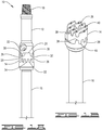
- drive shaft configuration 10 includes a first input shaft 12, a wear disk 14 and a second input shaft 16.
- First input shaft 12 has a first end 18 and a second end 20.
- Second input shaft 16 has a first end 22 and a second end 24.
- Wear disk 14 has a first wear surface 26 and a second wear surface 28.
- First end 18 of first input shaft 12 and second end 24 of second input shaft 16 may be threaded or configured in any convenient manner for securing to other components in a drive train or a drill string.
- Second end 20 of first input shaft 12 has at least one slot 30 and at least one outwardly projecting ridge 32.
- first end 22 of second input shaft 16 has at least one slot 34 and at least one outwardly projecting ridge 36.
- Each wear surface 26 and 28 of wear disk 14 has a corresponding slot 38 and a corresponding ridge 40 configured to receive or mate with slots 30, 34 and ridges 32, 36 of input shafts 12, 16.
- slots 30, 34, 38 and ridges 32, 36, 40 may vary with the use of drive shaft configuration 10. Suitable configurations include, but are not limited to, rectangular, trapezoidal (i.e. tapered), triangular and scalloped. Ridges and slots will generally have corners rounded to reduce friction and stress. Generally, ridges 32, 36, 40 will have a trapezoidal or tapered. Typically, a tapered or trapezoidal surface will allow for coupling wear without loss of face contact. Thus, this configuration extends coupling life by maintaining the relative alignment and configuration of coupling components. The height, width, taper angle and number of teeth can be varied for the coupling size and application.
- drive shaft configuration 10 utilizes reversed taper or a "dovetail" configuration for slots 30, 34, 38 and ridges 32, 36, 40.
- outwardly projecting ridges 40 carried by wear disk 14 optionally include lubrication grooves in the terminal surface. Although shown only on ridges 40 of wear disk 14, all contact surfaces of drive shaft configuration 10 may include lubrication grooves to enhance movement of drilling mud and other lubricants across and through drive shaft configuration 10.
- Wear disk 14 transfers torsional and axial forces received at first input shaft 12 to second input shaft 16 while accommodating eccentric or parallel offset shaft alignments thereby substantially eliminating or at least substantially minimizing angular changes in movement produced at either input shaft 12, 16.
- the configuration and cooperation of slots 30, 34, 38 and ridges 32, 36, 40 permit lateral slippage between input shafts 12, 16 and wear disk 14. Such movement between components will naturally produce surface wear.
- the configuration of wear disk 14 in cooperation with input shafts 12, 16 provides continuous structural alignment of coupling components, despite erosion of surfaces on wear disk 14 and input shafts 12, 16. Further alignment relationship is provided by a coupling housing 57 as depicted in FIG. 2 .
- wear disk 14 will generally be manufactured from a high-strength alloy steel, such as 300M, 4340, 8620 or a stainless steel composition identical to that used for the shafts 12 and 16 with all contact surfaces carrying optional hard coatings such as a ceramic based or cobalt-tungsten carbide coating to provide additional wear and abrasion resistance.
- wear disk 14 may be made from a sacrificial material such as a high strength bronze.
- all sliding or contact surfaces 26, 28, and ends 20, 22 will carry a wear and abrasion resistant surface treatment.
- the unique, unsecured, arrangement of wear disk 14 between input shafts 12, 16 provides for the efficient translation of rotational energy between non-aligned input shafts, i.e. input shafts having offset, parallel axes of rotations.
- the configuration of input shafts 12, 16 and wear disk 14 reduces g-force values experienced by drive shaft configuration 10 by about 80% to about 93% when compared to a conventional "jaw clutch" coupling currently used by the industry thereby reducing shock to internal components, providing quieter operations and lengthening the operational life of drive shaft configuration 10.
- drive shaft configuration 10 carries a double knuckle coupling 400 secured to end 24 of second input shaft 16.
- Double knuckle coupling 400 includes a coupling input yoke 402, a coupling center element 404 and a coupling output yoke 406.
- a bent housing 408, also known as a bend housing may house double knuckle coupling 400 if drive shaft 10 is utilized in a mud motor transmission.
- Double knuckle coupling 400 may be secured to any conventional bit box or secured to other driven downhole tools known to those skilled in the art.
- double knuckle coupling 400 may be secured to any driven component in a manner suitable to transmit torque to the driven component.
- drive shaft configuration 10 when incorporated into mud motor transmission 100 provides the capability to drive a drill bit during directional drilling operations while providing a readily replaceable coupling.
- the present invention provides significant additional advantages.
- Double knuckle coupling 400 is secured to end 24 of shaft 16 by any conventional means suitable for the intended use of drive shaft 10.
- Coupling input yoke 402 has a first end and a second end. The first end is secured to end 24. Second end has a slot 436 defining a tongue and groove configuration. Each tongue 434 has an arcuate recess 432.
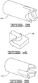
- Coupling center element 404 has a first tongue 415 configured to be received within slot 436 and a second tongue 417 configured to be received within slot 439 of coupling output yoke 406.
- center coupling element carries two pairs of arcuate knuckles 411 configured to be received within the respective arcuate recesses of coupling input yoke 402 and coupling output yoke 406.
- Each faces 416 of each tongue 415, 417 act as torque reaction faces 416 suitable for transferring torque from input yoke to output yoke.
- knuckles 411 have a radius transition from the arcuate surface to the torque reaction face that further enhances torque transfer by accommodating axial forces applied to the coupling input yoke.
- the relative lengths of each tongue of the components in the second coupling may vary depending upon the components driven by the shafts connected by the describe couplings.
- all of the components may be positioned within a housing.
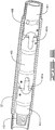
- a drive shaft 10 having two double knuckle couplings 400 may be placed within bent sub-housing 408 or substituted for any drive shaft having two CV joints or universal joints.
- the drive shaft includes an input shaft 403, a center shaft 410, an output shaft 407 and two coupling center elements 404.
- the input shaft 403, first center coupling 404a and first end of the center shaft 410 define a first double knuckle coupling.
- the output shaft 407, second center coupling 404b and second end of the center shaft 410 define a second double knuckle coupling.
- input shaft 403 functionally corresponds to input yoke 402
- output shaft 407 functionally corresponds to output yoke 406.
- each coupling yoke defines a tongue and groove arrangement with each tongue 438 having an arcuate recess 432.
- Slots 437 defined by the first and second coupling yokes may be in-line with one another or out of alignment with one another.
- the first end of the input shaft 403 is configured for attachment to a power input component and the second end of the input shaft 403 defines a tongue and groove arrangement with each tongue 434 having an arcuate recess 432.
- the input shaft may be an integral component or the input shaft may carry an input shaft adapter 412 suitable for securing the input shaft to a driving component.
- input shaft adapter 412 has an internal hex 413.
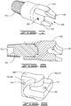
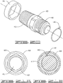
- FIGS. 18-21 depict a more typical embodiment of input shaft adapter 412. As depicted therein, input shaft adapter 412 has an external wrenching hex 421.
- a lockwire 442 Prior to installation of input shaft adapter 412 on input shaft, a lockwire 442 is placed over the threads 444 of input shaft adapter 412.
- a lockwire 442 is inserted through a hole 447 in input shaft 403 and conforms around grooves 449 in input shaft adapter 412 and input shaft 403 (groove not shown on input shaft).
- a machineable washer 440 is placed over wrenching hex 421. Machineable washer 440 protects wrenching hex 421 from damage and provides a smooth transition from input shaft 403 to input shaft adapter 412.
- the first end of the output shaft 407 defines a tongue and groove arrangement with each tongue 441 having an arcuate recess 443 and the second end of the output shaft configured to be attached to a driven component.
- the output shaft is an integral component including fluid flow ports 422 suitable for use as a flow diverter in the downhole environment.
- the output shaft carries an output shaft adapter suitable for securing to a driven component such as a flow diverter or other driven component.
- each tongue on input shaft 403, center shaft 410 and output shaft 407 has at least one retaining pin bore or hole 424, 418 and 420 respectively.
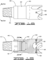
- Each coupling center element 404 has first and second tongues 415, 417 with each tongue defining a torque reaction face 416. Additionally, each coupling center has two pair of knuckles 411 configured to be received within the arcuate recesses of each tongue. As depicted, coupling center element 404 is symmetrical and may be installed with either tongue "up or down.” In each pair of knuckles, a knuckle 411 is located on each side of the coupling center's tongues 415, 417. Thus, the knuckles 411 are separated or spaced apart an appropriate distance for alignment with the arcuate recesses of the respective receiving tongues.
- the first tongue 415 is positioned within the slot 436 defined by the tongue and groove configuration carried by the input shaft 403 and the first knuckles 411 are received within the arcuate recesses 432 of the input shaft's tongues 434.
- the second tongue 417 of the first coupling center element 404a is positioned within the slot 437a defined by the tongue and groove configuration carried by the first end of the center shaft 410 and the second knuckles 411 of the first coupling center element 404a are positioned within the arcuate recesses 432a of the tongues 438 of the first end of the center shaft 410.
- first tongue of the second coupling center element 404b is positioned within the slot 437b defined by the tongue and groove configuration of the second end of the center shaft 410 with the first pair of knuckles 411 carried by the second coupling center element 404b positioned within the arcuate recesses 432b of the tongues 438 of the second end of the center shaft 410.
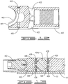
- Retaining pins 426 have a loose, clearance fitting within holes 418, 420 or 424. Further pins 426 have a loose, clearance fitting within the closed bottom holes 414 of center coupling element 404. However to ensure freedom of movement about pin 426 during pivotal movement of each double knuckle coupling 400, holes 414 are larger in diameter than holes 418, 420 and 424. Thus, the freedom of movement provided by the retaining pins 426 within holes 414, 418, 420 and 424 enables pivotal movement about points X and Y as depicted in FIG. 17 . Finally, pipe plugs 428 or equivalent elements placed over pins 426 secure retaining pins 426 in the holes of double knuckle coupling 400.
- output shaft 407 was adapted for use in a mud motor transmission. As depicted in FIGS 11-12 , the second end of output shaft was threaded for securing to a bit box or other downhole tool. Additionally, output shaft 407 included mud flow passage ports 422. However, output shaft 407 may be adapted for any power output configuration for above surface or downhole use. As depicted in FIGS. 15-16 , output shaft 407 carries an output shaft adapter 409 suitable for connecting to a cross-flow diverter, as depicted, or to any other driven component including but not limited to a differential, a transmission gear box or any similar device requiring input of power.
- the drive shaft incorporates two double knuckle couplings as discussed above.
- the second double knuckle coupling includes output shaft 407, which will have a first end with the same tongue and groove configuration as the first end of output shaft 407. The only difference being the configuration of the second end of output shaft 407.
- output shaft 407 carries output shaft adapter 409.
- Output shaft adapter 409 has a first end secured by any conventional means to the second end of output shaft 407, as depicted, the connection is provided by threads.
- the second end of output shaft 432 may carry threads or any other configuration suitable for connecting to a driven component or an additional shaft.
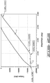
- FIGS. 6-21 To demonstrate the improvement provided by the configuration depicted in FIGS. 6-21 , the embodiment of FIGS. 6-21 was tested on a Dyna Drill dynamometer. The shaft was run for a period of 14 hours at 4,000 pound ⁇ feet of torque (about 5423 Nm of torque; also the maximum rating for the mud motor used) using water only to represent the drilling fluid. Following this test, the same driveshaft was fitted to a torsional test machine at LORD Corporation. A 300,000 pound ⁇ inch torque cell (about a 33.9 KNm torque cell) was used to measure the torque during the testing. In the test environment, housing 408 was omitted as being unnecessary.
- FIGS. 22-23 indicate that the shaft performed as expected during the test and that the threaded joint between the test machine and threaded stud continued to slip or yield toward the upper limits of the testing.
- a drive shaft 10 incorporating two double knuckle joints 400 will provide improved transmission of torque from input shaft 403 to output shaft 407.
- the configuration depicted in FIGS. 6-21 provides two torque paths.
- the first torque path follows the tongue and groove components of input shaft 403, center shaft 410, output shaft 407 and center coupling elements 404a and 404b.
- torque applied to input shaft 403 passes from tongue 434 to torque transfer faces 416 of tongue 415 of center coupling element 404a.
- Center coupling element torque transfer faces 416 of tongue 417 in turn transfers torque to tongues 438 forming first slot 437a.
- tongues 438 at slot 437b transfer torque to torque transfer faces 416 of tongue 415 of center coupling element 404b.
- torque transfer faces 416 of tongue 417 of center coupling element 404b transfers torque to tongues 441 of output shaft 407.
- the second torque path provides improved efficiencies.
- the second torque path utilizes the arcuate contact points of the double knuckle joint 400.
- each tongue 434 of the input shaft 407 has an arcuate recess 432.
- each tongue of center shaft 410 has a tongue 438 with an arcuate recess 432 and each tongue 441 of output shaft 407 has an arcuate recess 443.
- the arcuate recesses in the tongues of the input shaft, 403, center shaft 410 and output shaft 407 have radii corresponding to the arcuate surface of each knuckle 411 of center coupling elements 404.
- the second torque path follows the arcuate recesses of the tongues and arcuate surfaces of the knuckles until reaching output shaft 407.
Landscapes
- Engineering & Computer Science (AREA)
- General Engineering & Computer Science (AREA)
- Mechanical Engineering (AREA)
- Mining & Mineral Resources (AREA)
- Life Sciences & Earth Sciences (AREA)
- Geology (AREA)
- Fluid Mechanics (AREA)
- Environmental & Geological Engineering (AREA)
- Physics & Mathematics (AREA)
- General Life Sciences & Earth Sciences (AREA)
- Geochemistry & Mineralogy (AREA)
- Shafts, Cranks, Connecting Bars, And Related Bearings (AREA)
- Earth Drilling (AREA)
Claims (3)
- Un accouplement à rotules doubles (400), comprenant :un arbre d'entrée (403), ledit arbre d'entrée (403) ayant une première extrémité et une deuxième extrémité, ladite deuxième extrémité ayant une fente (436) définissant une configuration en languettes (434) et rainures, dans lequel chaque languette (434) a un renfoncement arqué (432) ;un arbre de sortie (407), ledit arbre de sortie (407) ayant une première extrémité et une deuxième extrémité, ladite première extrémité ayant une fente (439) définissant une configuration en languettes (441) et rainures, dans lequel chaque languette a un renfoncement arqué (443) ;un élément d'accouplement central (404),caractérisé en ce que ledit élément d'accouplement central (404) a une première languette (415) configurée pour être reçue à l'intérieur de ladite fente (439) de ladite deuxième extrémité dudit arbre d'entrée (403) et une deuxième languette (417) configurée pour être reçue à l'intérieur de la fente (439) de ladite première extrémité dudit arbre de sortie (407) ;dans lequel ledit élément d'accouplement central (404) comprend en sus deux paires de rotules (411), lesdites rotules (411) ayant une surface arquée configurée pour être reçue à l'intérieur desdits renfoncements arqués (432, 443) desdites languettes (434, 441) dudit arbre d'entrée (403) et dudit arbre de sortie (407).
- L'accouplement à rotules doubles de la revendication 1, dans lequel chaque languette dudit élément d'accouplement central (404) comprend en sus une face de réaction de couple (416), dans lequel une transition radiale raccorde ladite face de réaction de couple (416) à la surface arquée de ladite rotule (411).
- L'accouplement à rotules doubles de la revendication 2, dans lequel au moins une face de réaction de couple (416) a un alésage pour goupille de retenue (418).
Applications Claiming Priority (2)
| Application Number | Priority Date | Filing Date | Title |
|---|---|---|---|
| US201461988688P | 2014-05-05 | 2014-05-05 | |
| PCT/US2014/064080 WO2015171176A1 (fr) | 2014-05-05 | 2014-11-05 | Transmission de moteur à boue |
Publications (2)
| Publication Number | Publication Date |
|---|---|
| EP3140491A1 EP3140491A1 (fr) | 2017-03-15 |
| EP3140491B1 true EP3140491B1 (fr) | 2020-09-02 |
Family
ID=52007268
Family Applications (1)
| Application Number | Title | Priority Date | Filing Date |
|---|---|---|---|
| EP14806764.8A Active EP3140491B1 (fr) | 2014-05-05 | 2014-11-05 | Transmission de moteur à boue |
Country Status (7)
| Country | Link |
|---|---|
| US (1) | US10487882B2 (fr) |
| EP (1) | EP3140491B1 (fr) |
| JP (1) | JP2017515015A (fr) |
| KR (1) | KR20170005445A (fr) |
| CN (1) | CN106255833B (fr) |
| CA (1) | CA2946191C (fr) |
| WO (1) | WO2015171176A1 (fr) |
Families Citing this family (9)
| Publication number | Priority date | Publication date | Assignee | Title |
|---|---|---|---|---|
| US11072980B2 (en) | 2015-05-19 | 2021-07-27 | Halliburton Energy Services, Inc. | Constant-velocity joint with surface contact forks |
| US10934778B2 (en) | 2016-09-30 | 2021-03-02 | Abaco Drilling Technologies, LLC | BHA transmission with laminated rubber bearings |
| US11815139B2 (en) | 2016-09-30 | 2023-11-14 | Abaco Drilling Technologies Llc | PDM transmission with sliding contact between convex shaft pins and concave bearings surfaces |
| EP3604845A4 (fr) * | 2017-03-30 | 2020-11-04 | NSK Ltd. | Joint de transmission de couple et dispositif de servodirection électrique |
| US11661972B2 (en) | 2019-02-21 | 2023-05-30 | Abaco Drilling Technologies Llc | PDM transmission with ball-CV torque transfer |
| EP3947893B1 (fr) * | 2019-04-01 | 2025-05-07 | LORD Corporation | Isolateur latéral |
| KR102149976B1 (ko) | 2019-07-12 | 2020-08-31 | 산동금속공업(주) | 스레드의 체결 구조를 개선한 방향성 추진체 |
| CN111266630B (zh) * | 2020-02-28 | 2022-05-13 | 上海盈为机器人有限公司 | 一种钻孔用浮动头和浮动钻孔装置 |
| US11905764B1 (en) | 2020-12-09 | 2024-02-20 | IBEX Drilling Solutions, Inc. | Coupling with enhanced torsional, fatigue strength, and wear resistance |
Family Cites Families (23)
| Publication number | Priority date | Publication date | Assignee | Title |
|---|---|---|---|---|
| US3125022A (en) * | 1964-03-17 | Registering adjustment for multi-color printing | ||
| US1206669A (en) * | 1916-01-29 | 1916-11-28 | Jesse P Carter | Swinging chair. |
| US1625511A (en) * | 1923-12-21 | 1927-04-19 | Ungerer Karl Friedrich | Shaft coupling |
| US2451791A (en) * | 1945-01-25 | 1948-10-19 | Towmotor Corp | Universal joint |
| DE1206669B (de) * | 1964-03-06 | 1965-12-09 | Th Pernin & Fils Sa | Universalgelenk mit zwei Gabeln |
| US4452592A (en) * | 1982-06-01 | 1984-06-05 | General Motors Corporation | Cyclic phase change coupling |
| US4599056A (en) * | 1983-01-28 | 1986-07-08 | Smith International, Inc. | Universal joint and progressive cavity transducer using the same |
| FR2544422B1 (fr) * | 1983-04-18 | 1988-05-20 | Alsthom Atlantique | Dispositif d'accouplement a petit debattement pour arbres oscillants |
| US4547101A (en) * | 1983-09-20 | 1985-10-15 | Dowdakin Sr William J | Self-aligning tool holder |
| US4560368A (en) * | 1984-08-31 | 1985-12-24 | Allied Corporation | Single pin universal joint |
| US4941861A (en) * | 1987-12-28 | 1990-07-17 | Electronic Instrument & Specialty Corp. | Interlocking shaft coupling |
| US5022645A (en) * | 1988-11-25 | 1991-06-11 | Eastman Kodak Company | Disengageable coupling usable in a sheet transport mechanism |
| CA1314863C (fr) * | 1989-04-14 | 1993-03-23 | Dean Foote | Configuration de joint universel pour outils de fond de trou |
| JPH03125022A (ja) * | 1989-10-09 | 1991-05-28 | Koyo Seiko Co Ltd | 玉型自在継手の組立方法 |
| US5288271A (en) * | 1992-04-13 | 1994-02-22 | Houston Engineers, Inc. | Constant velocity universal joint assembly for downhole motor |
| US6517439B1 (en) * | 2001-09-19 | 2003-02-11 | Maytag Corporation | U-joint construction |
| US6875114B2 (en) * | 2003-03-21 | 2005-04-05 | Kelsey-Hayes Company | Tapered coupling |
| CA2646968C (fr) * | 2008-04-30 | 2013-02-26 | Dreco Energy Services Ltd. | Arbre d'entrainement pour moteur de fond |
| DE102009053129A1 (de) * | 2009-11-13 | 2011-05-19 | Sms Siemag Ag | Gleitstein für eine Gelenkspindel |
| CN102478082B (zh) * | 2010-11-30 | 2014-04-30 | 鸿富锦精密工业(深圳)有限公司 | 万向节 |
| FR2977627B1 (fr) * | 2011-07-08 | 2016-02-05 | Somfy Sas | Dispositif d'accouplement et installation domotique comprenant un tel dispositif |
| DE102011118655A1 (de) * | 2011-11-12 | 2013-05-16 | Alfred Heyd GmbH & Co. KG | Gelenk für eine Gelenkwelle |
| US20150167399A1 (en) * | 2012-08-03 | 2015-06-18 | Lord Corporation | Coupling and mud motor transmission |
-
2014
- 2014-11-05 EP EP14806764.8A patent/EP3140491B1/fr active Active
- 2014-11-05 KR KR1020167033938A patent/KR20170005445A/ko not_active Withdrawn
- 2014-11-05 US US15/303,647 patent/US10487882B2/en active Active
- 2014-11-05 CA CA2946191A patent/CA2946191C/fr active Active
- 2014-11-05 WO PCT/US2014/064080 patent/WO2015171176A1/fr not_active Ceased
- 2014-11-05 CN CN201480078574.9A patent/CN106255833B/zh not_active Expired - Fee Related
- 2014-11-05 JP JP2016562572A patent/JP2017515015A/ja active Pending
Non-Patent Citations (1)
| Title |
|---|
| None * |
Also Published As
| Publication number | Publication date |
|---|---|
| US20170045090A1 (en) | 2017-02-16 |
| CA2946191A1 (fr) | 2015-11-12 |
| KR20170005445A (ko) | 2017-01-13 |
| CN106255833B (zh) | 2021-06-25 |
| EP3140491A1 (fr) | 2017-03-15 |
| CA2946191C (fr) | 2021-08-24 |
| JP2017515015A (ja) | 2017-06-08 |
| CN106255833A (zh) | 2016-12-21 |
| US10487882B2 (en) | 2019-11-26 |
| WO2015171176A1 (fr) | 2015-11-12 |
Similar Documents
| Publication | Publication Date | Title |
|---|---|---|
| EP3140491B1 (fr) | Transmission de moteur à boue | |
| US20150167399A1 (en) | Coupling and mud motor transmission | |
| EP2274526B1 (fr) | Ensemble arbre d'entraînement pour un moteur de fond de trou | |
| US10508493B2 (en) | Universal joint | |
| US10288065B1 (en) | Mud motor coupling system | |
| US20190162242A1 (en) | Universal joint | |
| US10280683B1 (en) | Mud motor apparatus and system | |
| CA2971926A1 (fr) | Joint universel | |
| US10975623B2 (en) | High torque constant velocity joint for downhole drilling power transmission | |
| US20160108970A1 (en) | Articulated Drive Shaft | |
| US20160341255A1 (en) | Universal joint | |
| CA2966697A1 (fr) | Joint universel | |
| US5409324A (en) | High strength, quick connect/disconnect coupling | |
| EP3289161B1 (fr) | Joint cv pour moteur de forage | |
| WO2014107813A1 (fr) | Système, procédé et appareil pour un assemblage flexible pour un moteur de forage de fond de trou | |
| CN115182682B (zh) | 一种高可靠性柔性钻杆 | |
| US11905764B1 (en) | Coupling with enhanced torsional, fatigue strength, and wear resistance | |
| US10900287B2 (en) | Articulated joint for downhole steering assembly | |
| RU34664U1 (ru) | Муфта | |
| US11072980B2 (en) | Constant-velocity joint with surface contact forks |
Legal Events
| Date | Code | Title | Description |
|---|---|---|---|
| STAA | Information on the status of an ep patent application or granted ep patent |
Free format text: STATUS: THE INTERNATIONAL PUBLICATION HAS BEEN MADE |
|
| PUAI | Public reference made under article 153(3) epc to a published international application that has entered the european phase |
Free format text: ORIGINAL CODE: 0009012 |
|
| STAA | Information on the status of an ep patent application or granted ep patent |
Free format text: STATUS: REQUEST FOR EXAMINATION WAS MADE |
|
| 17P | Request for examination filed |
Effective date: 20161014 |
|
| AK | Designated contracting states |
Kind code of ref document: A1 Designated state(s): AL AT BE BG CH CY CZ DE DK EE ES FI FR GB GR HR HU IE IS IT LI LT LU LV MC MK MT NL NO PL PT RO RS SE SI SK SM TR |
|
| AX | Request for extension of the european patent |
Extension state: BA ME |
|
| DAX | Request for extension of the european patent (deleted) | ||
| STAA | Information on the status of an ep patent application or granted ep patent |
Free format text: STATUS: EXAMINATION IS IN PROGRESS |
|
| 17Q | First examination report despatched |
Effective date: 20190716 |
|
| RIC1 | Information provided on ipc code assigned before grant |
Ipc: F16D 3/26 20060101ALI20200207BHEP Ipc: F16D 47/02 20060101ALI20200207BHEP Ipc: F16D 3/04 20060101ALI20200207BHEP Ipc: E21B 17/02 20060101AFI20200207BHEP |
|
| GRAP | Despatch of communication of intention to grant a patent |
Free format text: ORIGINAL CODE: EPIDOSNIGR1 |
|
| STAA | Information on the status of an ep patent application or granted ep patent |
Free format text: STATUS: GRANT OF PATENT IS INTENDED |
|
| INTG | Intention to grant announced |
Effective date: 20200323 |
|
| GRAS | Grant fee paid |
Free format text: ORIGINAL CODE: EPIDOSNIGR3 |
|
| GRAA | (expected) grant |
Free format text: ORIGINAL CODE: 0009210 |
|
| STAA | Information on the status of an ep patent application or granted ep patent |
Free format text: STATUS: THE PATENT HAS BEEN GRANTED |
|
| AK | Designated contracting states |
Kind code of ref document: B1 Designated state(s): AL AT BE BG CH CY CZ DE DK EE ES FI FR GB GR HR HU IE IS IT LI LT LU LV MC MK MT NL NO PL PT RO RS SE SI SK SM TR |
|
| REG | Reference to a national code |
Ref country code: GB Ref legal event code: FG4D |
|
| REG | Reference to a national code |
Ref country code: AT Ref legal event code: REF Ref document number: 1308997 Country of ref document: AT Kind code of ref document: T Effective date: 20200915 Ref country code: CH Ref legal event code: EP |
|
| REG | Reference to a national code |
Ref country code: DE Ref legal event code: R096 Ref document number: 602014069757 Country of ref document: DE |
|
| REG | Reference to a national code |
Ref country code: IE Ref legal event code: FG4D |
|
| REG | Reference to a national code |
Ref country code: NO Ref legal event code: T2 Effective date: 20200902 |
|
| REG | Reference to a national code |
Ref country code: LT Ref legal event code: MG4D |
|
| PG25 | Lapsed in a contracting state [announced via postgrant information from national office to epo] |
Ref country code: FI Free format text: LAPSE BECAUSE OF FAILURE TO SUBMIT A TRANSLATION OF THE DESCRIPTION OR TO PAY THE FEE WITHIN THE PRESCRIBED TIME-LIMIT Effective date: 20200902 Ref country code: LT Free format text: LAPSE BECAUSE OF FAILURE TO SUBMIT A TRANSLATION OF THE DESCRIPTION OR TO PAY THE FEE WITHIN THE PRESCRIBED TIME-LIMIT Effective date: 20200902 Ref country code: BG Free format text: LAPSE BECAUSE OF FAILURE TO SUBMIT A TRANSLATION OF THE DESCRIPTION OR TO PAY THE FEE WITHIN THE PRESCRIBED TIME-LIMIT Effective date: 20201202 Ref country code: GR Free format text: LAPSE BECAUSE OF FAILURE TO SUBMIT A TRANSLATION OF THE DESCRIPTION OR TO PAY THE FEE WITHIN THE PRESCRIBED TIME-LIMIT Effective date: 20201203 Ref country code: HR Free format text: LAPSE BECAUSE OF FAILURE TO SUBMIT A TRANSLATION OF THE DESCRIPTION OR TO PAY THE FEE WITHIN THE PRESCRIBED TIME-LIMIT Effective date: 20200902 Ref country code: SE Free format text: LAPSE BECAUSE OF FAILURE TO SUBMIT A TRANSLATION OF THE DESCRIPTION OR TO PAY THE FEE WITHIN THE PRESCRIBED TIME-LIMIT Effective date: 20200902 |
|
| REG | Reference to a national code |
Ref country code: NL Ref legal event code: MP Effective date: 20200902 |
|
| REG | Reference to a national code |
Ref country code: AT Ref legal event code: MK05 Ref document number: 1308997 Country of ref document: AT Kind code of ref document: T Effective date: 20200902 |
|
| PG25 | Lapsed in a contracting state [announced via postgrant information from national office to epo] |
Ref country code: PL Free format text: LAPSE BECAUSE OF FAILURE TO SUBMIT A TRANSLATION OF THE DESCRIPTION OR TO PAY THE FEE WITHIN THE PRESCRIBED TIME-LIMIT Effective date: 20200902 Ref country code: LV Free format text: LAPSE BECAUSE OF FAILURE TO SUBMIT A TRANSLATION OF THE DESCRIPTION OR TO PAY THE FEE WITHIN THE PRESCRIBED TIME-LIMIT Effective date: 20200902 Ref country code: RS Free format text: LAPSE BECAUSE OF FAILURE TO SUBMIT A TRANSLATION OF THE DESCRIPTION OR TO PAY THE FEE WITHIN THE PRESCRIBED TIME-LIMIT Effective date: 20200902 |
|
| PG25 | Lapsed in a contracting state [announced via postgrant information from national office to epo] |
Ref country code: PT Free format text: LAPSE BECAUSE OF FAILURE TO SUBMIT A TRANSLATION OF THE DESCRIPTION OR TO PAY THE FEE WITHIN THE PRESCRIBED TIME-LIMIT Effective date: 20210104 Ref country code: NL Free format text: LAPSE BECAUSE OF FAILURE TO SUBMIT A TRANSLATION OF THE DESCRIPTION OR TO PAY THE FEE WITHIN THE PRESCRIBED TIME-LIMIT Effective date: 20200902 Ref country code: SM Free format text: LAPSE BECAUSE OF FAILURE TO SUBMIT A TRANSLATION OF THE DESCRIPTION OR TO PAY THE FEE WITHIN THE PRESCRIBED TIME-LIMIT Effective date: 20200902 Ref country code: RO Free format text: LAPSE BECAUSE OF FAILURE TO SUBMIT A TRANSLATION OF THE DESCRIPTION OR TO PAY THE FEE WITHIN THE PRESCRIBED TIME-LIMIT Effective date: 20200902 Ref country code: EE Free format text: LAPSE BECAUSE OF FAILURE TO SUBMIT A TRANSLATION OF THE DESCRIPTION OR TO PAY THE FEE WITHIN THE PRESCRIBED TIME-LIMIT Effective date: 20200902 Ref country code: CZ Free format text: LAPSE BECAUSE OF FAILURE TO SUBMIT A TRANSLATION OF THE DESCRIPTION OR TO PAY THE FEE WITHIN THE PRESCRIBED TIME-LIMIT Effective date: 20200902 |
|
| PG25 | Lapsed in a contracting state [announced via postgrant information from national office to epo] |
Ref country code: IS Free format text: LAPSE BECAUSE OF FAILURE TO SUBMIT A TRANSLATION OF THE DESCRIPTION OR TO PAY THE FEE WITHIN THE PRESCRIBED TIME-LIMIT Effective date: 20210102 Ref country code: ES Free format text: LAPSE BECAUSE OF FAILURE TO SUBMIT A TRANSLATION OF THE DESCRIPTION OR TO PAY THE FEE WITHIN THE PRESCRIBED TIME-LIMIT Effective date: 20200902 Ref country code: AT Free format text: LAPSE BECAUSE OF FAILURE TO SUBMIT A TRANSLATION OF THE DESCRIPTION OR TO PAY THE FEE WITHIN THE PRESCRIBED TIME-LIMIT Effective date: 20200902 Ref country code: AL Free format text: LAPSE BECAUSE OF FAILURE TO SUBMIT A TRANSLATION OF THE DESCRIPTION OR TO PAY THE FEE WITHIN THE PRESCRIBED TIME-LIMIT Effective date: 20200902 |
|
| REG | Reference to a national code |
Ref country code: DE Ref legal event code: R097 Ref document number: 602014069757 Country of ref document: DE |
|
| PG25 | Lapsed in a contracting state [announced via postgrant information from national office to epo] |
Ref country code: MC Free format text: LAPSE BECAUSE OF FAILURE TO SUBMIT A TRANSLATION OF THE DESCRIPTION OR TO PAY THE FEE WITHIN THE PRESCRIBED TIME-LIMIT Effective date: 20200902 Ref country code: SK Free format text: LAPSE BECAUSE OF FAILURE TO SUBMIT A TRANSLATION OF THE DESCRIPTION OR TO PAY THE FEE WITHIN THE PRESCRIBED TIME-LIMIT Effective date: 20200902 |
|
| REG | Reference to a national code |
Ref country code: CH Ref legal event code: PL |
|
| PLBE | No opposition filed within time limit |
Free format text: ORIGINAL CODE: 0009261 |
|
| STAA | Information on the status of an ep patent application or granted ep patent |
Free format text: STATUS: NO OPPOSITION FILED WITHIN TIME LIMIT |
|
| PG25 | Lapsed in a contracting state [announced via postgrant information from national office to epo] |
Ref country code: LU Free format text: LAPSE BECAUSE OF NON-PAYMENT OF DUE FEES Effective date: 20201105 |
|
| 26N | No opposition filed |
Effective date: 20210603 |
|
| REG | Reference to a national code |
Ref country code: BE Ref legal event code: MM Effective date: 20201130 |
|
| PG25 | Lapsed in a contracting state [announced via postgrant information from national office to epo] |
Ref country code: DK Free format text: LAPSE BECAUSE OF FAILURE TO SUBMIT A TRANSLATION OF THE DESCRIPTION OR TO PAY THE FEE WITHIN THE PRESCRIBED TIME-LIMIT Effective date: 20200902 Ref country code: CH Free format text: LAPSE BECAUSE OF NON-PAYMENT OF DUE FEES Effective date: 20201130 Ref country code: SI Free format text: LAPSE BECAUSE OF FAILURE TO SUBMIT A TRANSLATION OF THE DESCRIPTION OR TO PAY THE FEE WITHIN THE PRESCRIBED TIME-LIMIT Effective date: 20200902 Ref country code: LI Free format text: LAPSE BECAUSE OF NON-PAYMENT OF DUE FEES Effective date: 20201130 |
|
| PG25 | Lapsed in a contracting state [announced via postgrant information from national office to epo] |
Ref country code: IE Free format text: LAPSE BECAUSE OF NON-PAYMENT OF DUE FEES Effective date: 20201105 Ref country code: IT Free format text: LAPSE BECAUSE OF FAILURE TO SUBMIT A TRANSLATION OF THE DESCRIPTION OR TO PAY THE FEE WITHIN THE PRESCRIBED TIME-LIMIT Effective date: 20200902 |
|
| PG25 | Lapsed in a contracting state [announced via postgrant information from national office to epo] |
Ref country code: TR Free format text: LAPSE BECAUSE OF FAILURE TO SUBMIT A TRANSLATION OF THE DESCRIPTION OR TO PAY THE FEE WITHIN THE PRESCRIBED TIME-LIMIT Effective date: 20200902 Ref country code: MT Free format text: LAPSE BECAUSE OF FAILURE TO SUBMIT A TRANSLATION OF THE DESCRIPTION OR TO PAY THE FEE WITHIN THE PRESCRIBED TIME-LIMIT Effective date: 20200902 Ref country code: CY Free format text: LAPSE BECAUSE OF FAILURE TO SUBMIT A TRANSLATION OF THE DESCRIPTION OR TO PAY THE FEE WITHIN THE PRESCRIBED TIME-LIMIT Effective date: 20200902 |
|
| PG25 | Lapsed in a contracting state [announced via postgrant information from national office to epo] |
Ref country code: MK Free format text: LAPSE BECAUSE OF FAILURE TO SUBMIT A TRANSLATION OF THE DESCRIPTION OR TO PAY THE FEE WITHIN THE PRESCRIBED TIME-LIMIT Effective date: 20200902 |
|
| PG25 | Lapsed in a contracting state [announced via postgrant information from national office to epo] |
Ref country code: BE Free format text: LAPSE BECAUSE OF NON-PAYMENT OF DUE FEES Effective date: 20201130 |
|
| P01 | Opt-out of the competence of the unified patent court (upc) registered |
Effective date: 20230524 |
|
| PGFP | Annual fee paid to national office [announced via postgrant information from national office to epo] |
Ref country code: GB Payment date: 20231127 Year of fee payment: 10 |
|
| PGFP | Annual fee paid to national office [announced via postgrant information from national office to epo] |
Ref country code: NO Payment date: 20231129 Year of fee payment: 10 Ref country code: FR Payment date: 20231127 Year of fee payment: 10 Ref country code: DE Payment date: 20231129 Year of fee payment: 10 |
|
| REG | Reference to a national code |
Ref country code: DE Ref legal event code: R119 Ref document number: 602014069757 Country of ref document: DE |
|
| PG25 | Lapsed in a contracting state [announced via postgrant information from national office to epo] |
Ref country code: NO Free format text: LAPSE BECAUSE OF NON-PAYMENT OF DUE FEES Effective date: 20241130 |
|
| GBPC | Gb: european patent ceased through non-payment of renewal fee |
Effective date: 20241105 |
|
| PG25 | Lapsed in a contracting state [announced via postgrant information from national office to epo] |
Ref country code: DE Free format text: LAPSE BECAUSE OF NON-PAYMENT OF DUE FEES Effective date: 20250603 |
|
| PG25 | Lapsed in a contracting state [announced via postgrant information from national office to epo] |
Ref country code: GB Free format text: LAPSE BECAUSE OF NON-PAYMENT OF DUE FEES Effective date: 20241105 |
|
| PG25 | Lapsed in a contracting state [announced via postgrant information from national office to epo] |
Ref country code: FR Free format text: LAPSE BECAUSE OF NON-PAYMENT OF DUE FEES Effective date: 20241130 |