EP3140512B1 - Method for producing a construction element, in particular a tunnel element, having a watertight seal - Google Patents
Method for producing a construction element, in particular a tunnel element, having a watertight seal Download PDFInfo
- Publication number
- EP3140512B1 EP3140512B1 EP15718948.1A EP15718948A EP3140512B1 EP 3140512 B1 EP3140512 B1 EP 3140512B1 EP 15718948 A EP15718948 A EP 15718948A EP 3140512 B1 EP3140512 B1 EP 3140512B1
- Authority
- EP
- European Patent Office
- Prior art keywords
- tunnel
- gasket
- elements
- seal
- concrete
- Prior art date
- Legal status (The legal status is an assumption and is not a legal conclusion. Google has not performed a legal analysis and makes no representation as to the accuracy of the status listed.)
- Active
Links
Images




Classifications
-
- E—FIXED CONSTRUCTIONS
- E21—EARTH OR ROCK DRILLING; MINING
- E21D—SHAFTS; TUNNELS; GALLERIES; LARGE UNDERGROUND CHAMBERS
- E21D11/00—Lining tunnels, galleries or other underground cavities, e.g. large underground chambers; Linings therefor; Making such linings in situ, e.g. by assembling
- E21D11/38—Waterproofing; Heat insulating; Soundproofing; Electric insulating
- E21D11/385—Sealing means positioned between adjacent lining members
-
- B—PERFORMING OPERATIONS; TRANSPORTING
- B28—WORKING CEMENT, CLAY, OR STONE
- B28B—SHAPING CLAY OR OTHER CERAMIC COMPOSITIONS; SHAPING SLAG; SHAPING MIXTURES CONTAINING CEMENTITIOUS MATERIAL, e.g. PLASTER
- B28B23/00—Arrangements specially adapted for the production of shaped articles with elements wholly or partly embedded in the moulding material; Production of reinforced objects
- B28B23/0043—Arrangements specially adapted for the production of shaped articles with elements wholly or partly embedded in the moulding material; Production of reinforced objects with gaskets or sealing elements, e.g. for tunnelings or man holes
-
- E—FIXED CONSTRUCTIONS
- E02—HYDRAULIC ENGINEERING; FOUNDATIONS; SOIL SHIFTING
- E02D—FOUNDATIONS; EXCAVATIONS; EMBANKMENTS; UNDERGROUND OR UNDERWATER STRUCTURES
- E02D29/00—Independent underground or underwater structures; Retaining walls
- E02D29/063—Tunnels submerged into, or built in, open water
-
- E—FIXED CONSTRUCTIONS
- E02—HYDRAULIC ENGINEERING; FOUNDATIONS; SOIL SHIFTING
- E02D—FOUNDATIONS; EXCAVATIONS; EMBANKMENTS; UNDERGROUND OR UNDERWATER STRUCTURES
- E02D29/00—Independent underground or underwater structures; Retaining walls
- E02D29/063—Tunnels submerged into, or built in, open water
- E02D29/073—Tunnels or shuttering therefor assembled from sections individually sunk onto, or laid on, the water-bed, e.g. in a preformed trench
-
- E—FIXED CONSTRUCTIONS
- E02—HYDRAULIC ENGINEERING; FOUNDATIONS; SOIL SHIFTING
- E02D—FOUNDATIONS; EXCAVATIONS; EMBANKMENTS; UNDERGROUND OR UNDERWATER STRUCTURES
- E02D29/00—Independent underground or underwater structures; Retaining walls
- E02D29/16—Arrangement or construction of joints in foundation structures
-
- E—FIXED CONSTRUCTIONS
- E02—HYDRAULIC ENGINEERING; FOUNDATIONS; SOIL SHIFTING
- E02D—FOUNDATIONS; EXCAVATIONS; EMBANKMENTS; UNDERGROUND OR UNDERWATER STRUCTURES
- E02D31/00—Protective arrangements for foundations or foundation structures; Ground foundation measures for protecting the soil or the subsoil water, e.g. preventing or counteracting oil pollution
- E02D31/02—Protective arrangements for foundations or foundation structures; Ground foundation measures for protecting the soil or the subsoil water, e.g. preventing or counteracting oil pollution against ground humidity or ground water
-
- E—FIXED CONSTRUCTIONS
- E21—EARTH OR ROCK DRILLING; MINING
- E21D—SHAFTS; TUNNELS; GALLERIES; LARGE UNDERGROUND CHAMBERS
- E21D11/00—Lining tunnels, galleries or other underground cavities, e.g. large underground chambers; Linings therefor; Making such linings in situ, e.g. by assembling
- E21D11/04—Lining with building materials
- E21D11/08—Lining with building materials with preformed concrete slabs
- E21D11/086—Methods of making concrete lining segments
-
- E—FIXED CONSTRUCTIONS
- E02—HYDRAULIC ENGINEERING; FOUNDATIONS; SOIL SHIFTING
- E02D—FOUNDATIONS; EXCAVATIONS; EMBANKMENTS; UNDERGROUND OR UNDERWATER STRUCTURES
- E02D2600/00—Miscellaneous
- E02D2600/20—Miscellaneous comprising details of connection between elements
-
- E—FIXED CONSTRUCTIONS
- E21—EARTH OR ROCK DRILLING; MINING
- E21D—SHAFTS; TUNNELS; GALLERIES; LARGE UNDERGROUND CHAMBERS
- E21D11/00—Lining tunnels, galleries or other underground cavities, e.g. large underground chambers; Linings therefor; Making such linings in situ, e.g. by assembling
- E21D11/04—Lining with building materials
- E21D11/08—Lining with building materials with preformed concrete slabs
-
- E—FIXED CONSTRUCTIONS
- E21—EARTH OR ROCK DRILLING; MINING
- E21D—SHAFTS; TUNNELS; GALLERIES; LARGE UNDERGROUND CHAMBERS
- E21D11/00—Lining tunnels, galleries or other underground cavities, e.g. large underground chambers; Linings therefor; Making such linings in situ, e.g. by assembling
- E21D11/38—Waterproofing; Heat insulating; Soundproofing; Electric insulating
- E21D11/383—Waterproofing; Heat insulating; Soundproofing; Electric insulating by applying waterproof flexible sheets; Means for fixing the sheets to the tunnel or cavity wall
Definitions
- the invention relates to a method for producing a tubular tunnel element from concrete, in a mould, for an immersed tunnel wherein the tubular tunnel elements are placed against one another with a water tight seal in between the outer ends thereof, said tubular tunnel element being provided with a watertight seal on at least one outer end thereof, wherein an endless gasket is produced comprising a deforming body which is produced from a yielding material, such as rubber, and a base which is produced from a relatively strong material.
- An immersed tunnel is normally constructed from structural concrete elements approximately 100-150 meters long, which are manufactured in a casting basin or dry dock.
- the tunnel elements are provided with temporary bulkheads at both ends to ensure that the element is watertight and capable of floating.
- an endless gasket is mounted on one end of each tunnel element.
- the dock is flooded and the elements floated.
- Each element is towed to its final position and then immersed.
- the immersed tunnel element is then pulled firmly up against the preceding immersed element with hydraulic jacks.
- the initial contact of the gasket should be accomplished using a low pulling force. When the gasket has full contact around the total circumference of the adjacent element, the water between the bulkheads is pumped out.
- the gasket profile compresses and seals the joint.
- a secondary seal is then clamped across the joint on the inside of the tunnel.
- the bulkheads are removed after approval of the pressure test between the gasket and the secondary seal.
- the supplier of the gasket needs to show by calculations based on the measured force-compression curves that at all water pressures the selected gasket satisfies the following conditions within agreed safety limits:
- the gaskets are mounted on the ends of the tunnel element using an end frame which is first attached to the ends of the tunnel element, and then one side of the gasket is mounted in the frame.
- the end frame is usually made of carbon steel or stainless steel. Mounting the end frames to the tunnel elements and mounting the gasket in the frames is however time consuming.
- the aim of the invention is to provide a cheap, reliable and fast manner to produce and place construction elements such as tunnel elements.
- the base is provided with anchors made of metal or carbon on one side thereof, the base with the deforming body is placed against an inner side of the mould, wherein the concrete is cast in the mould, and the anchors extend into the concrete while the concrete is cured to form the tubular tunnel element with the watertight seal.
- said base is provided with anchors on one side thereof, said anchors extending into the curing material while said material is cured, a chemical and or mechanical bond can be obtained.
- EP 1 054 204 A2 discloses concrete tubular sewer pipe elements with a rubber seal, wherein a rubber anchor part of the seal is enclosed in the curing concrete.
- the engaging ends of the sewer pipes are mutually mechanically locked in a form-fitted manner in their lateral/radial direction.
- said anchors extend from a plate which is at least partially surrounded by said yielding material of the gasket in order to hold said plate.
- Said plate is also preferably made of metal or carbon.
- Said anchors comprise bolts, which are screwed into said plate so as to extend therefrom.
- said anchors are plate shaped, wherein said plate shaped elements extend in the curing material parallel to a surface of the curing material.
- the invention also relates to a tunnel element produced by the method as described before.
- the invention furthermore relates to a tunnel wherein tubular tunnel elements produced by the method as described before are placed against one another with said seal in between the outer ends thereof.
- a secondary seal is provided over said seal against the inner side of said tunnel.
- an immersed tunnel is constructed from structural concrete tunnel elements 1.
- the tunnel elements 1 are provided with temporary bulkheads 2 at both ends to ensure that the element is watertight and capable of floating.
- Each tunnel element 1 is towed to its final position and then immersed.
- an endless gasket 3 is mounted on one end of each tunnel element 1.
- the immersed tunnel element 1 is pulled firmly up against the preceding immersed tunnel element 1, as shown in figure 4 .
- the gasket 3 has full contact around the total circumference of the adjacent tunnel element 1
- the water between the bulkheads 2 is pumped out as shown in figure 5 .
- a secondary seal 4 is then clamped across the joint on the inside of the tunnel elements 1.
- the bulkheads2 are then removed as shown in figure 6 .
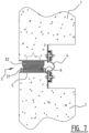
- Figure 7 shows a prior art seal of the joint between two tunnel elements 1.
- the endless gasket 3 is profiled, having a base mounting portion 31 and a compressing body 32.
- a slot is provided at both sides of the gasket 3, in which metal strips can engage in order to hold the gasket 3.
- the method for mounting the gasket to the tunnel element 1 is as follows. First an end-frame 5 is provided on the outer end of the cured concrete tunnel element 1. Then the endless gasket 3 is laid out in the correct rectangular shape, flat on a floor (for instance the roof of the tunnel element 1. A lifting beam with nylon straps engages the top section and the lower section of the gasket 3, and the gasket 3 is lifted to the vertical position. The gasket 3 is placed in front of and against the end-frame 5 on the outer end of the tunnel element 1, and on both side of the gasket 3 a metal hooked profiled mounting strip 6 is inserted in the slot between the mounting portion 31 and the compressing body 32, whereafter the mounting strips 6 are attached to the end-frame 5 by means of bolts.
- the gasket 3 is directly casted with the tunnel element, eliminating the steel end-frame 5 and mounting strips 6 as shown in figure 7 . Separate installation is no longer required.
- the gasket 3 is placed in a special mould. This mould is used to cast the front section of the tunnel element 1. After curing of the concrete and releasing of the mould the gasket 3 is permanently connected with the tunnel element 1.
- the gasket 3 comprises an endless compressing body 32 made from vulcanized rubber.
- the compressing body has a generally rectangular, almost square and slightly tapering, cross section.
- a rib 33 is formed which can be easily be deformed upon first contact with the opposing tunnel element 1.
- base elements 34 comprising plate shaped elements 341 are enclosed in the rubber material near or at the surface of the compressing body 32. In this embodiment the base elements 34 and the deforming body 32 are not detachable from each other thereby.
- the plate shaped element 341 is made of carbon fibre or fabric inlay material. Over the length of the plate shaped element 34 pairs of bolts 342 with bolt heads are screwed through the plate shaped element 341, so as to form anchors. On the other side of the plate shaped elements 34 the bolts 342 are secured by nuts 343. The base elements 34 together with the deforming body 32 are cast integral with the concrete.
- the gasket 3 comprises an endless compressing body 32 made from vulcanized rubber.
- the compressing body 32 has a generally rectangular, almost square and slightly tapering, cross section.
- a rib 33 is formed which can be easily be deformed upon first contact with the opposing tunnel element 1.
- plate shaped mounting elements 321 are formed integral with the compressing body 32.
- Base elements 34 in the form of plate shaped elements are cast integral with the concrete of the tunnel elements. The base 34 and the compressing body 32 are detachable from each other and are attached to each other by means of screws 35.
- the gasket 3 comprises an endless compressing body 32 made from vulcanized rubber.
- the compressing body 32 has a generally rectangular, almost square and slightly tapering, cross section.
- a rib 33 is formed which can be easily be deformed upon first contact with the opposing tunnel element 1.
- the compressing body is formed with a base mounting portion 31. Between the mounting portion 31 and the compressing body 32 a slot is provided at both sides of the compressing body 32, in which metal strips can engage in order to hold the compressing body 32.
- Base elements 34 comprising plate shaped elements 341 are cast integral with the concrete of the tunnel elements.
- the base element 34 further comprises a metal hooked profiled mounting strip 347 mounted on the plate shaped element 341 which can be inserted in the slot between the mounting portion 31 and the compressing body 32.
- the base 34 and the compressing body 32 are thus detachable from each other and are attached to each other by means of a separate metal hooked profiled mounting strip 37 which can be mounted on the plate shaped element 341 by means of screws 35.
- the gasket 3 comprises an endless compressing body 32 made from vulcanized rubber.
- the compressing body 32 has a generally rectangular, almost square and slightly tapering, cross section.
- a rib 33 is formed which can be easily be deformed upon first contact with the opposing tunnel element 1.
- plate shaped mounting elements 321 are formed integral with the compressing body 32, on both sides of the centre line.
- a V-shaped recess is provided, which allows for manual inward compression of the sides of the compressing body.
- Base elements 34 comprising plate shaped elements 341 are cast integral with the concrete of the tunnel elements. From the edges of the plate shaped element 341 extend strips 348in the direction of the central-top part of the compressing body. The base 34 and the compressing body 32 are detachable from each other and are attached to each other by compressing the lower part of the compressing body 32 such that it can snap behind the edges of the strips 348 as shown in figure 13 .
Landscapes
- Engineering & Computer Science (AREA)
- Structural Engineering (AREA)
- Mining & Mineral Resources (AREA)
- Life Sciences & Earth Sciences (AREA)
- General Life Sciences & Earth Sciences (AREA)
- Civil Engineering (AREA)
- General Engineering & Computer Science (AREA)
- Environmental & Geological Engineering (AREA)
- Paleontology (AREA)
- Architecture (AREA)
- Geochemistry & Mineralogy (AREA)
- Geology (AREA)
- Mechanical Engineering (AREA)
- Ceramic Engineering (AREA)
- Chemical & Material Sciences (AREA)
- Manufacturing & Machinery (AREA)
- Hydrology & Water Resources (AREA)
- Lining And Supports For Tunnels (AREA)
Priority Applications (1)
| Application Number | Priority Date | Filing Date | Title |
|---|---|---|---|
| HRP20230408TT HRP20230408T1 (hr) | 2014-05-06 | 2015-05-01 | Postupak proizvodnje konstrukcijskog elementa, posebno građevnog elementa tunela, koji ima vodonepropusni izolacijski spoj |
Applications Claiming Priority (2)
| Application Number | Priority Date | Filing Date | Title |
|---|---|---|---|
| NL2012765A NL2012765B1 (en) | 2014-05-06 | 2014-05-06 | Method for producing a construction element, in particular a tunnel element, having a watertight seal. |
| PCT/EP2015/059619 WO2015169707A2 (en) | 2014-05-06 | 2015-05-01 | Method for producing a construction element, in particular a tunnel element, having a watertight seal |
Publications (2)
| Publication Number | Publication Date |
|---|---|
| EP3140512A2 EP3140512A2 (en) | 2017-03-15 |
| EP3140512B1 true EP3140512B1 (en) | 2023-03-22 |
Family
ID=51266393
Family Applications (1)
| Application Number | Title | Priority Date | Filing Date |
|---|---|---|---|
| EP15718948.1A Active EP3140512B1 (en) | 2014-05-06 | 2015-05-01 | Method for producing a construction element, in particular a tunnel element, having a watertight seal |
Country Status (12)
| Country | Link |
|---|---|
| US (1) | US10018043B2 (da) |
| EP (1) | EP3140512B1 (da) |
| CN (1) | CN106460357B (da) |
| DK (1) | DK3140512T3 (da) |
| ES (1) | ES2944129T3 (da) |
| FI (1) | FI3140512T3 (da) |
| HR (1) | HRP20230408T1 (da) |
| LT (1) | LT3140512T (da) |
| NL (1) | NL2012765B1 (da) |
| PL (1) | PL3140512T3 (da) |
| PT (1) | PT3140512T (da) |
| WO (1) | WO2015169707A2 (da) |
Families Citing this family (11)
| Publication number | Priority date | Publication date | Assignee | Title |
|---|---|---|---|---|
| CN106988346B (zh) * | 2017-03-24 | 2019-12-31 | 中国交通建设股份有限公司 | 沉管隧道最终接头及预制方法、安装方法 |
| EE05838B1 (et) * | 2018-02-02 | 2021-10-15 | Tõnu Ader | Survestatavate tihenditega moodultunnel ja selle vette paigaldamise meetod |
| NL2020541B1 (en) | 2018-03-06 | 2019-09-13 | Fugro N V | Position Monitoring of a Gasket between Tunnel Segments |
| CN109372544A (zh) * | 2018-11-28 | 2019-02-22 | 中铁隧道集团二处有限公司 | 隧道管节间密封结构及其施工方法 |
| CN109736357A (zh) * | 2019-02-25 | 2019-05-10 | 中建四局第一建筑工程有限公司 | 一种地下室底板后浇带施工缝优化处理结构 |
| CN110219669B (zh) * | 2019-04-30 | 2021-03-16 | 东北大学 | 一种楔入式预制盾构管片防水结构 |
| CN110284521A (zh) * | 2019-07-31 | 2019-09-27 | 招商局重庆交通科研设计院有限公司 | 一种采用超高性能混凝土后浇接头的隧道结构及安装方法 |
| CN112031028B (zh) * | 2020-08-19 | 2022-02-15 | 广船国际有限公司 | 一种提高钢壳止水带套筒安装精度的方法 |
| US11306530B1 (en) * | 2020-09-24 | 2022-04-19 | Karl Krause | Garage floor barricade and associated methods |
| JP7307863B2 (ja) * | 2021-11-15 | 2023-07-12 | 中交第一航▲務▼工程局有限公司 | 吊り下げ摺動式止水装置及びその応用 |
| JP7792692B2 (ja) * | 2022-03-02 | 2025-12-26 | 西武ポリマ化成株式会社 | 可撓止水部材の取付構造 |
Citations (1)
| Publication number | Priority date | Publication date | Assignee | Title |
|---|---|---|---|---|
| EP1054204A2 (fr) * | 1999-05-15 | 2000-11-22 | Bonna Sabla | Tuyau, notamment en beton, comportant un joint d'étanchéité et procédé de fabrication d'un tel tuyau |
Family Cites Families (27)
| Publication number | Priority date | Publication date | Assignee | Title |
|---|---|---|---|---|
| US1774664A (en) * | 1926-03-18 | 1930-09-02 | Walter C Parmley | Joint for conduits |
| US3111811A (en) * | 1956-12-15 | 1963-11-26 | Nederlanden Staat | Method for the construction of a tunnel or tunnel-part and a tunnel or tunnel-part obtained by pursuing said method |
| US3750411A (en) * | 1970-04-16 | 1973-08-07 | S Shimizu | Joint for under-water structures |
| JPS4820260B1 (da) * | 1970-09-10 | 1973-06-20 | ||
| GB1381292A (en) * | 1971-01-11 | 1975-01-22 | Cooper E F | Tunnelling |
| WO1979000921A1 (en) * | 1978-04-12 | 1979-11-15 | Sheridan Contractors Ltd | Tunnel lining,segment therefore and method of lining a tunnel |
| DE3800630A1 (de) * | 1988-01-12 | 1989-07-20 | Thyssen Industrie | Tunnelausbau aus segmenten |
| GB2228957B (en) * | 1989-03-08 | 1992-10-21 | Charcon Tunnels Ltd | Improvements in or relating to arcuate pre-cast concrete tunnel lining segments |
| FR2669259A1 (fr) * | 1990-11-21 | 1992-05-22 | Tuyaux Bonna | Procede de fabrication de voussoirs prefabriques. |
| ATE171758T1 (de) * | 1993-01-14 | 1998-10-15 | Phoenix Ag | Dichtungsprofil für tunnelrohrsegmente, insbesondere für einschwimmelemente |
| KR100214113B1 (ko) * | 1993-05-11 | 1999-08-02 | 오가사와라 쇼헤이 | 터널라이너 그 제조방법 및 그 제조장치 |
| FR2712655B1 (fr) * | 1993-11-19 | 1996-02-02 | Tuyaux Bonna | Joint d'étanchéité. |
| JP2796437B2 (ja) * | 1995-02-01 | 1998-09-10 | フェニックス アクチエンゲゼルシャフト | トンネル管セグメントのシール構造 |
| ES2122802T3 (es) * | 1995-03-01 | 1998-12-16 | Phoenix Ag | Junta de estanqueidad y su procedimiento de realizacion. |
| WO1998016721A1 (en) * | 1996-10-15 | 1998-04-23 | C. I. Kasei Co., Ltd. | Resin-coated segment, and manufacture thereof |
| NL1005140C2 (nl) | 1997-01-30 | 1998-08-03 | Trelleborg Bakker B V | Afdichtprofiel voor tunnelsegmenten en tunnel, voorzien van dergelijke afdichtprofielen. |
| GB2330156A (en) * | 1997-10-07 | 1999-04-14 | Tarmac Uk Ltd | Reinforced shaft, tunnel or pipeline segment |
| CH696445A5 (de) * | 2003-09-09 | 2007-06-15 | Aldo Ceresola | Betonelement zum Verkleiden eines Tunnels. |
| JP4074848B2 (ja) * | 2003-11-17 | 2008-04-16 | 住友ゴム工業株式会社 | 沈埋函の接合構造 |
| CN100371538C (zh) | 2005-08-05 | 2008-02-27 | 上海市隧道工程轨道交通设计研究院 | 止水带的组合安装方法 |
| RU2536720C2 (ru) * | 2010-01-12 | 2014-12-27 | Херренкнехт Аг | Защитный элемент, бетонный элемент и способ изготовления бетонного элемента |
| DE102011115715A1 (de) * | 2011-10-12 | 2013-04-18 | Meese GmbH | Halterung zum Eingießen in ein Betonelement |
| CN103291320A (zh) | 2012-03-03 | 2013-09-11 | 四川华西绿舍预制构件有限公司 | 密封箱涵 |
| ITPN20120025A1 (it) * | 2012-05-25 | 2013-11-26 | Fama S P A | Dispositivo di tenuta per la sigillatura di blocchi di calcestruzzo e relativo metodo di fabbricazione |
| CN103437791B (zh) * | 2013-09-13 | 2016-02-17 | 中铁隧道集团二处有限公司 | 一种隧道衬砌台车端头中埋式止水带的安装方法 |
| CN103670451B (zh) | 2013-12-09 | 2016-05-25 | 中铁五局(集团)有限公司 | 一种隧道中埋式纵向橡胶止水带安装器具及使用方法 |
| CN103670452B (zh) | 2013-12-23 | 2016-05-25 | 中铁五局(集团)有限公司 | 一种用于隧道拱墙衬砌中埋式止水带准确定位的安装结构及方法 |
-
2014
- 2014-05-06 NL NL2012765A patent/NL2012765B1/en active
-
2015
- 2015-05-01 ES ES15718948T patent/ES2944129T3/es active Active
- 2015-05-01 PL PL15718948.1T patent/PL3140512T3/pl unknown
- 2015-05-01 CN CN201580023420.4A patent/CN106460357B/zh active Active
- 2015-05-01 PT PT157189481T patent/PT3140512T/pt unknown
- 2015-05-01 FI FIEP15718948.1T patent/FI3140512T3/fi active
- 2015-05-01 US US15/308,794 patent/US10018043B2/en active Active
- 2015-05-01 WO PCT/EP2015/059619 patent/WO2015169707A2/en not_active Ceased
- 2015-05-01 EP EP15718948.1A patent/EP3140512B1/en active Active
- 2015-05-01 DK DK15718948.1T patent/DK3140512T3/da active
- 2015-05-01 HR HRP20230408TT patent/HRP20230408T1/hr unknown
- 2015-05-01 LT LTEPPCT/EP2015/059619T patent/LT3140512T/lt unknown
Patent Citations (1)
| Publication number | Priority date | Publication date | Assignee | Title |
|---|---|---|---|---|
| EP1054204A2 (fr) * | 1999-05-15 | 2000-11-22 | Bonna Sabla | Tuyau, notamment en beton, comportant un joint d'étanchéité et procédé de fabrication d'un tel tuyau |
Also Published As
| Publication number | Publication date |
|---|---|
| WO2015169707A2 (en) | 2015-11-12 |
| FI3140512T3 (fi) | 2023-05-03 |
| CN106460357A (zh) | 2017-02-22 |
| US10018043B2 (en) | 2018-07-10 |
| PT3140512T (pt) | 2023-05-29 |
| PL3140512T3 (pl) | 2023-10-16 |
| DK3140512T3 (da) | 2023-04-24 |
| CN106460357B (zh) | 2019-03-15 |
| HRP20230408T1 (hr) | 2023-09-15 |
| US20170175527A1 (en) | 2017-06-22 |
| WO2015169707A3 (en) | 2016-04-07 |
| EP3140512A2 (en) | 2017-03-15 |
| ES2944129T3 (es) | 2023-06-19 |
| LT3140512T (lt) | 2023-05-10 |
| NL2012765B1 (en) | 2016-02-23 |
Similar Documents
| Publication | Publication Date | Title |
|---|---|---|
| EP3140512B1 (en) | Method for producing a construction element, in particular a tunnel element, having a watertight seal | |
| EP3480369B1 (en) | Integrated immersed tube section and installation method thereof as well as installation and closure method of immersed tube sections | |
| US8628275B1 (en) | Structural bonded repair method for repairing tubular members in an offshore marine environment | |
| US9297136B2 (en) | Inflatable dam assembly | |
| US20110041438A1 (en) | Construction of a wind energy plant | |
| KR100959301B1 (ko) | 터널구조물과 이를 이용한 터널 및 터널 시공방법 | |
| CN103857857B (zh) | 用预制墙壁部件组装墙壁的方法和墙壁组件 | |
| CN110409327A (zh) | 拼装式内衬箱涵 | |
| CN207538837U (zh) | 一体化沉管管节 | |
| JP5022947B2 (ja) | 仮締切作業函およびその設置方法 | |
| CN113152698A (zh) | 一种用于构筑物变形缝处止水带结构及其施工方法 | |
| CN207144000U (zh) | 最终接头舾装件 | |
| JP4954914B2 (ja) | 水中構造物の仮締切工法及び仮締切用構造体 | |
| CN107524170A (zh) | 最终接头舾装件及拆除方法 | |
| CN204898609U (zh) | 一种下沉式面板缝止水防护结构 | |
| CN220704353U (zh) | 桥墩加固实施结构 | |
| KR101002281B1 (ko) | 수중축조물 보수용 물막이 구조물 | |
| KR102475974B1 (ko) | 수중 구조물의 보수·보강 방법 | |
| CN108589797B (zh) | 一种地下结构与墩柱分离式节点防水系统 | |
| JP7736968B1 (ja) | 防水装置、膨張部材及び防水壁の形成方法 | |
| JP2645985B2 (ja) | 護岸ブロック間のシール材及びその施工方法 | |
| CN104775445B (zh) | 一种挂式沉箱装置 | |
| CN209891240U (zh) | 一种涵洞的临时封堵装置 | |
| CN213805525U (zh) | 一种地下连续墙断墙处理装置 | |
| KR20120109167A (ko) | 농수로용 신축이음장치 및 이의 시공방법 |
Legal Events
| Date | Code | Title | Description |
|---|---|---|---|
| REG | Reference to a national code |
Ref country code: HR Ref legal event code: TUEP Ref document number: P20230408T Country of ref document: HR |
|
| STAA | Information on the status of an ep patent application or granted ep patent |
Free format text: STATUS: THE INTERNATIONAL PUBLICATION HAS BEEN MADE |
|
| PUAI | Public reference made under article 153(3) epc to a published international application that has entered the european phase |
Free format text: ORIGINAL CODE: 0009012 |
|
| STAA | Information on the status of an ep patent application or granted ep patent |
Free format text: STATUS: REQUEST FOR EXAMINATION WAS MADE |
|
| 17P | Request for examination filed |
Effective date: 20161117 |
|
| AK | Designated contracting states |
Kind code of ref document: A2 Designated state(s): AL AT BE BG CH CY CZ DE DK EE ES FI FR GB GR HR HU IE IS IT LI LT LU LV MC MK MT NL NO PL PT RO RS SE SI SK SM TR |
|
| AX | Request for extension of the european patent |
Extension state: BA ME |
|
| DAV | Request for validation of the european patent (deleted) | ||
| DAX | Request for extension of the european patent (deleted) | ||
| STAA | Information on the status of an ep patent application or granted ep patent |
Free format text: STATUS: EXAMINATION IS IN PROGRESS |
|
| 17Q | First examination report despatched |
Effective date: 20170922 |
|
| GRAP | Despatch of communication of intention to grant a patent |
Free format text: ORIGINAL CODE: EPIDOSNIGR1 |
|
| STAA | Information on the status of an ep patent application or granted ep patent |
Free format text: STATUS: GRANT OF PATENT IS INTENDED |
|
| INTG | Intention to grant announced |
Effective date: 20221017 |
|
| GRAS | Grant fee paid |
Free format text: ORIGINAL CODE: EPIDOSNIGR3 |
|
| GRAA | (expected) grant |
Free format text: ORIGINAL CODE: 0009210 |
|
| STAA | Information on the status of an ep patent application or granted ep patent |
Free format text: STATUS: THE PATENT HAS BEEN GRANTED |
|
| AK | Designated contracting states |
Kind code of ref document: B1 Designated state(s): AL AT BE BG CH CY CZ DE DK EE ES FI FR GB GR HR HU IE IS IT LI LT LU LV MC MK MT NL NO PL PT RO RS SE SI SK SM TR |
|
| REG | Reference to a national code |
Ref country code: GB Ref legal event code: FG4D |
|
| REG | Reference to a national code |
Ref country code: CH Ref legal event code: EP |
|
| REG | Reference to a national code |
Ref country code: IE Ref legal event code: FG4D |
|
| REG | Reference to a national code |
Ref country code: DE Ref legal event code: R096 Ref document number: 602015082875 Country of ref document: DE |
|
| REG | Reference to a national code |
Ref country code: AT Ref legal event code: REF Ref document number: 1555399 Country of ref document: AT Kind code of ref document: T Effective date: 20230415 |
|
| REG | Reference to a national code |
Ref country code: DK Ref legal event code: T3 Effective date: 20230417 |
|
| REG | Reference to a national code |
Ref country code: SE Ref legal event code: TRGR |
|
| REG | Reference to a national code |
Ref country code: PT Ref legal event code: SC4A Ref document number: 3140512 Country of ref document: PT Date of ref document: 20230529 Kind code of ref document: T Free format text: AVAILABILITY OF NATIONAL TRANSLATION Effective date: 20230522 |
|
| REG | Reference to a national code |
Ref country code: HR Ref legal event code: ODRP Ref document number: P20230408T Country of ref document: HR Payment date: 20230502 Year of fee payment: 9 |
|
| REG | Reference to a national code |
Ref country code: NO Ref legal event code: T2 Effective date: 20230322 |
|
| REG | Reference to a national code |
Ref country code: EE Ref legal event code: FG4A Ref document number: E023279 Country of ref document: EE Effective date: 20230424 |
|
| REG | Reference to a national code |
Ref country code: ES Ref legal event code: FG2A Ref document number: 2944129 Country of ref document: ES Kind code of ref document: T3 Effective date: 20230619 |
|
| P01 | Opt-out of the competence of the unified patent court (upc) registered |
Effective date: 20230515 |
|
| REG | Reference to a national code |
Ref country code: NL Ref legal event code: FP |
|
| REG | Reference to a national code |
Ref country code: GR Ref legal event code: EP Ref document number: 20230400720 Country of ref document: GR Effective date: 20230613 |
|
| PG25 | Lapsed in a contracting state [announced via postgrant information from national office to epo] |
Ref country code: RS Free format text: LAPSE BECAUSE OF FAILURE TO SUBMIT A TRANSLATION OF THE DESCRIPTION OR TO PAY THE FEE WITHIN THE PRESCRIBED TIME-LIMIT Effective date: 20230322 |
|
| REG | Reference to a national code |
Ref country code: HR Ref legal event code: T1PR Ref document number: P20230408 Country of ref document: HR |
|
| PG25 | Lapsed in a contracting state [announced via postgrant information from national office to epo] |
Ref country code: SM Free format text: LAPSE BECAUSE OF FAILURE TO SUBMIT A TRANSLATION OF THE DESCRIPTION OR TO PAY THE FEE WITHIN THE PRESCRIBED TIME-LIMIT Effective date: 20230322 |
|
| PG25 | Lapsed in a contracting state [announced via postgrant information from national office to epo] |
Ref country code: SK Free format text: LAPSE BECAUSE OF FAILURE TO SUBMIT A TRANSLATION OF THE DESCRIPTION OR TO PAY THE FEE WITHIN THE PRESCRIBED TIME-LIMIT Effective date: 20230322 |
|
| REG | Reference to a national code |
Ref country code: DE Ref legal event code: R097 Ref document number: 602015082875 Country of ref document: DE |
|
| PG25 | Lapsed in a contracting state [announced via postgrant information from national office to epo] |
Ref country code: MC Free format text: LAPSE BECAUSE OF FAILURE TO SUBMIT A TRANSLATION OF THE DESCRIPTION OR TO PAY THE FEE WITHIN THE PRESCRIBED TIME-LIMIT Effective date: 20230322 |
|
| PLBE | No opposition filed within time limit |
Free format text: ORIGINAL CODE: 0009261 |
|
| STAA | Information on the status of an ep patent application or granted ep patent |
Free format text: STATUS: NO OPPOSITION FILED WITHIN TIME LIMIT |
|
| PG25 | Lapsed in a contracting state [announced via postgrant information from national office to epo] |
Ref country code: SI Free format text: LAPSE BECAUSE OF FAILURE TO SUBMIT A TRANSLATION OF THE DESCRIPTION OR TO PAY THE FEE WITHIN THE PRESCRIBED TIME-LIMIT Effective date: 20230322 Ref country code: MC Free format text: LAPSE BECAUSE OF FAILURE TO SUBMIT A TRANSLATION OF THE DESCRIPTION OR TO PAY THE FEE WITHIN THE PRESCRIBED TIME-LIMIT Effective date: 20230322 Ref country code: LU Free format text: LAPSE BECAUSE OF NON-PAYMENT OF DUE FEES Effective date: 20230501 Ref country code: CZ Free format text: LAPSE BECAUSE OF FAILURE TO SUBMIT A TRANSLATION OF THE DESCRIPTION OR TO PAY THE FEE WITHIN THE PRESCRIBED TIME-LIMIT Effective date: 20230322 |
|
| REG | Reference to a national code |
Ref country code: AT Ref legal event code: UEP Ref document number: 1555399 Country of ref document: AT Kind code of ref document: T Effective date: 20230322 |
|
| 26N | No opposition filed |
Effective date: 20240102 |
|
| REG | Reference to a national code |
Ref country code: HR Ref legal event code: ODRP Ref document number: P20230408 Country of ref document: HR Payment date: 20240418 Year of fee payment: 10 |
|
| REG | Reference to a national code |
Ref country code: HR Ref legal event code: ODRP Ref document number: P20230408 Country of ref document: HR Payment date: 20250425 Year of fee payment: 11 |
|
| PGFP | Annual fee paid to national office [announced via postgrant information from national office to epo] |
Ref country code: NL Payment date: 20250526 Year of fee payment: 11 |
|
| PGFP | Annual fee paid to national office [announced via postgrant information from national office to epo] |
Ref country code: FI Payment date: 20250526 Year of fee payment: 11 |
|
| PGFP | Annual fee paid to national office [announced via postgrant information from national office to epo] |
Ref country code: PL Payment date: 20250422 Year of fee payment: 11 Ref country code: DE Payment date: 20250529 Year of fee payment: 11 |
|
| PGFP | Annual fee paid to national office [announced via postgrant information from national office to epo] |
Ref country code: ES Payment date: 20250602 Year of fee payment: 11 Ref country code: GB Payment date: 20250527 Year of fee payment: 11 Ref country code: DK Payment date: 20250526 Year of fee payment: 11 |
|
| PGFP | Annual fee paid to national office [announced via postgrant information from national office to epo] |
Ref country code: LT Payment date: 20250422 Year of fee payment: 11 |
|
| PGFP | Annual fee paid to national office [announced via postgrant information from national office to epo] |
Ref country code: IS Payment date: 20250513 Year of fee payment: 11 Ref country code: NO Payment date: 20250530 Year of fee payment: 11 |
|
| PGFP | Annual fee paid to national office [announced via postgrant information from national office to epo] |
Ref country code: IT Payment date: 20250521 Year of fee payment: 11 Ref country code: BE Payment date: 20250527 Year of fee payment: 11 |
|
| PGFP | Annual fee paid to national office [announced via postgrant information from national office to epo] |
Ref country code: HR Payment date: 20250425 Year of fee payment: 11 |
|
| PGFP | Annual fee paid to national office [announced via postgrant information from national office to epo] |
Ref country code: LV Payment date: 20250506 Year of fee payment: 11 Ref country code: PT Payment date: 20250421 Year of fee payment: 11 |
|
| PGFP | Annual fee paid to national office [announced via postgrant information from national office to epo] |
Ref country code: EE Payment date: 20250507 Year of fee payment: 11 Ref country code: FR Payment date: 20250526 Year of fee payment: 11 |
|
| PGFP | Annual fee paid to national office [announced via postgrant information from national office to epo] |
Ref country code: MT Payment date: 20250506 Year of fee payment: 11 Ref country code: GR Payment date: 20250528 Year of fee payment: 11 Ref country code: BG Payment date: 20250514 Year of fee payment: 11 |
|
| PGFP | Annual fee paid to national office [announced via postgrant information from national office to epo] |
Ref country code: CH Payment date: 20250601 Year of fee payment: 11 |
|
| PGFP | Annual fee paid to national office [announced via postgrant information from national office to epo] |
Ref country code: RO Payment date: 20250429 Year of fee payment: 11 Ref country code: AT Payment date: 20250505 Year of fee payment: 11 |
|
| PG25 | Lapsed in a contracting state [announced via postgrant information from national office to epo] |
Ref country code: CY Free format text: LAPSE BECAUSE OF FAILURE TO SUBMIT A TRANSLATION OF THE DESCRIPTION OR TO PAY THE FEE WITHIN THE PRESCRIBED TIME-LIMIT; INVALID AB INITIO Effective date: 20150501 |
|
| PGFP | Annual fee paid to national office [announced via postgrant information from national office to epo] |
Ref country code: TR Payment date: 20250428 Year of fee payment: 11 |
|
| PGFP | Annual fee paid to national office [announced via postgrant information from national office to epo] |
Ref country code: IE Payment date: 20250527 Year of fee payment: 11 |
|
| PGFP | Annual fee paid to national office [announced via postgrant information from national office to epo] |
Ref country code: SE Payment date: 20250527 Year of fee payment: 11 |
|
| PG25 | Lapsed in a contracting state [announced via postgrant information from national office to epo] |
Ref country code: HU Free format text: LAPSE BECAUSE OF FAILURE TO SUBMIT A TRANSLATION OF THE DESCRIPTION OR TO PAY THE FEE WITHIN THE PRESCRIBED TIME-LIMIT; INVALID AB INITIO Effective date: 20150501 |