EP3140527B1 - Chambre de combustion pour moteur à combustion interne, et moteur à combustion interne - Google Patents
Chambre de combustion pour moteur à combustion interne, et moteur à combustion interne Download PDFInfo
- Publication number
- EP3140527B1 EP3140527B1 EP14890716.5A EP14890716A EP3140527B1 EP 3140527 B1 EP3140527 B1 EP 3140527B1 EP 14890716 A EP14890716 A EP 14890716A EP 3140527 B1 EP3140527 B1 EP 3140527B1
- Authority
- EP
- European Patent Office
- Prior art keywords
- piston
- internal combustion
- combustion engine
- combustion chamber
- cylinder
- Prior art date
- Legal status (The legal status is an assumption and is not a legal conclusion. Google has not performed a legal analysis and makes no representation as to the accuracy of the status listed.)
- Active
Links
Images



Classifications
-
- F—MECHANICAL ENGINEERING; LIGHTING; HEATING; WEAPONS; BLASTING
- F02—COMBUSTION ENGINES; HOT-GAS OR COMBUSTION-PRODUCT ENGINE PLANTS
- F02B—INTERNAL-COMBUSTION PISTON ENGINES; COMBUSTION ENGINES IN GENERAL
- F02B23/00—Other engines characterised by special shape or construction of combustion chambers to improve operation
- F02B23/02—Other engines characterised by special shape or construction of combustion chambers to improve operation with compression ignition
- F02B23/06—Other engines characterised by special shape or construction of combustion chambers to improve operation with compression ignition the combustion space being arranged in working piston
- F02B23/0618—Other engines characterised by special shape or construction of combustion chambers to improve operation with compression ignition the combustion space being arranged in working piston having in-cylinder means to influence the charge motion
- F02B23/0624—Swirl flow
-
- F—MECHANICAL ENGINEERING; LIGHTING; HEATING; WEAPONS; BLASTING
- F02—COMBUSTION ENGINES; HOT-GAS OR COMBUSTION-PRODUCT ENGINE PLANTS
- F02B—INTERNAL-COMBUSTION PISTON ENGINES; COMBUSTION ENGINES IN GENERAL
- F02B23/00—Other engines characterised by special shape or construction of combustion chambers to improve operation
- F02B23/02—Other engines characterised by special shape or construction of combustion chambers to improve operation with compression ignition
- F02B23/06—Other engines characterised by special shape or construction of combustion chambers to improve operation with compression ignition the combustion space being arranged in working piston
- F02B23/0645—Details related to the fuel injector or the fuel spray
- F02B23/066—Details related to the fuel injector or the fuel spray the injector being located substantially off-set from the cylinder centre axis
-
- F—MECHANICAL ENGINEERING; LIGHTING; HEATING; WEAPONS; BLASTING
- F02—COMBUSTION ENGINES; HOT-GAS OR COMBUSTION-PRODUCT ENGINE PLANTS
- F02B—INTERNAL-COMBUSTION PISTON ENGINES; COMBUSTION ENGINES IN GENERAL
- F02B23/00—Other engines characterised by special shape or construction of combustion chambers to improve operation
- F02B23/02—Other engines characterised by special shape or construction of combustion chambers to improve operation with compression ignition
- F02B23/06—Other engines characterised by special shape or construction of combustion chambers to improve operation with compression ignition the combustion space being arranged in working piston
- F02B23/0645—Details related to the fuel injector or the fuel spray
- F02B23/0663—Details related to the fuel injector or the fuel spray having multiple injectors per combustion chamber
-
- F—MECHANICAL ENGINEERING; LIGHTING; HEATING; WEAPONS; BLASTING
- F02—COMBUSTION ENGINES; HOT-GAS OR COMBUSTION-PRODUCT ENGINE PLANTS
- F02B—INTERNAL-COMBUSTION PISTON ENGINES; COMBUSTION ENGINES IN GENERAL
- F02B23/00—Other engines characterised by special shape or construction of combustion chambers to improve operation
- F02B23/02—Other engines characterised by special shape or construction of combustion chambers to improve operation with compression ignition
- F02B23/06—Other engines characterised by special shape or construction of combustion chambers to improve operation with compression ignition the combustion space being arranged in working piston
- F02B23/0645—Details related to the fuel injector or the fuel spray
- F02B23/0666—Details related to the fuel injector or the fuel spray having a single fuel spray jet per injector nozzle
-
- F—MECHANICAL ENGINEERING; LIGHTING; HEATING; WEAPONS; BLASTING
- F02—COMBUSTION ENGINES; HOT-GAS OR COMBUSTION-PRODUCT ENGINE PLANTS
- F02B—INTERNAL-COMBUSTION PISTON ENGINES; COMBUSTION ENGINES IN GENERAL
- F02B23/00—Other engines characterised by special shape or construction of combustion chambers to improve operation
- F02B23/02—Other engines characterised by special shape or construction of combustion chambers to improve operation with compression ignition
- F02B23/06—Other engines characterised by special shape or construction of combustion chambers to improve operation with compression ignition the combustion space being arranged in working piston
- F02B23/0678—Unconventional, complex or non-rotationally symmetrical shapes of the combustion space, e.g. flower like, having special shapes related to the orientation of the fuel spray jets
- F02B23/0687—Multiple bowls in the piston, e.g. one bowl per fuel spray jet
-
- F—MECHANICAL ENGINEERING; LIGHTING; HEATING; WEAPONS; BLASTING
- F02—COMBUSTION ENGINES; HOT-GAS OR COMBUSTION-PRODUCT ENGINE PLANTS
- F02B—INTERNAL-COMBUSTION PISTON ENGINES; COMBUSTION ENGINES IN GENERAL
- F02B25/00—Engines characterised by using fresh charge for scavenging cylinders
- F02B25/02—Engines characterised by using fresh charge for scavenging cylinders using unidirectional scavenging
- F02B25/08—Engines with oppositely-moving reciprocating working pistons
-
- Y—GENERAL TAGGING OF NEW TECHNOLOGICAL DEVELOPMENTS; GENERAL TAGGING OF CROSS-SECTIONAL TECHNOLOGIES SPANNING OVER SEVERAL SECTIONS OF THE IPC; TECHNICAL SUBJECTS COVERED BY FORMER USPC CROSS-REFERENCE ART COLLECTIONS [XRACs] AND DIGESTS
- Y02—TECHNOLOGIES OR APPLICATIONS FOR MITIGATION OR ADAPTATION AGAINST CLIMATE CHANGE
- Y02T—CLIMATE CHANGE MITIGATION TECHNOLOGIES RELATED TO TRANSPORTATION
- Y02T10/00—Road transport of goods or passengers
- Y02T10/10—Internal combustion engine [ICE] based vehicles
- Y02T10/12—Improving ICE efficiencies
Definitions
- Opposed piston engines include a cylinder with a pair of pistons that move toward each other toward top dead center positions to compress gas in the cylinder and near which fuel is injected through a side wall of the cylinder.
- U.S. Patent App. US2012/0285418 and U.S. Patent App. US2013/0036999 describe the general structure and operation of an opposed piston engine.
- U.S. Patent App. US2012/0285418 observes that such engines require different arrangements for effective mixing of fuel and air. Providing for effective mixing of fuel in air in conventional engine cylinders is, of course, also important.
- the present invention concerns a combustion chamber according to claim 1.
- an engine comprising such a combustion chamber is provided.
- EP 2 712 394 A1 relates to an opposed-piston engine including a ported cylinder and a pair of pistons disposed to reciprocate in the bore of the cylinder.
- a combustion chamber is defined by opposing shaped piston end surfaces as the pistons approach respective top dead center locations in the bore.
- the shaped end surfaces of the pistons interact with swirl to produce turbulence in the charge air motion in the combustion chamber; the additional bulk motions include tumble.
- Fuel is injected into the turbulent charge air motion along a major axis, of the combustion chamber.
- US 2013/025556 A1 relates to a combustion chamber in an opposed-piston, internal-combustion engine in which the pistons tops are designed so that when they approach each other, they induce a tumble flow in one or two hemispherical spaces defined in the piston tops.
- the combustion chamber further includes injectors side mounted in the cylinder wall.
- the tumble flows in the two hemispheres are in the same direction and in another embodiment, in opposite directions.
- DE 10 2012 111776 A1 relates to a toroidal combustion chamber shape with side injectors developed for an opposed-piston engine. Favourable combustion characteristics of such configuration are transferred to a conventional engine, i.e., one with a combustion chamber delimited by a piston, a cylinder wall, and a cylinder head. At least one injector is disposed in the cylinder head at the periphery. The fuel is injected substantially along the plane of interface between the cylinder head and the cylinder block.
- the intake system is configured to provide a swirling flow in the combustion chamber. The fuel is injected in an angle that is displaced from the central axis of the cylinder and directed along the swirl.
- a substantially torus-shaped volume is formed between the piston and the cylinder head when the piston is at top center. The injector or injectors spray fuel into the toroidally-shaped volume substantially tangent to the torus.
- DE 32 14 096 A1 relates to a diesel engine with direct fuel injection having a cylinder bore with a diameter of less than 100 mm.
- a piston head has a recess with a diameter of less than half the diameter of the cylinder bore.
- the recess together with a cylinder head forms a combustion chamber.
- a spiral inlet duct creates a swirling movement of air in the cylinder bore with a swirl ratio of 1.0 to 3.0.
- Two diametrically opposing fuel injection nozzles are provided. Each fuel injection nozzle opens at a tangent to the combustion chamber and produces a jet of fuel with the same direction as that of the air swirl.
- US2013/014718 A1 relates to a toroidal combustion chamber shape with a side injector for an opposed-piston engine. Fuel is injected into the toroidal volume from a fuel injector in the cylinder wall. In one embodiment, fuel is injected from each injector a plurality of times with the timing between the injections such that fuel clouds from each injection remain substantially isolated from each other. Further combustion chambers are shown by Documents JP S6314836 U and GB 1076317 .
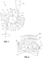
- FIG. 1 An internal combustion engine 21 according to an aspect of the present invention is seen in FIG. 1 and comprises a combustion chamber 23 comprising a cylinder wall 25 defining a cylinder 27.
- the cylinder wall 25 is ordinarily part of a cylinder liner or an engine block.
- a fuel injector 29 is disposed in a first opening 31 in the cylinder wall 25.
- a piston head 33 is movably disposed in the cylinder 25 and is linked to a crankshaft (not shown in FIGS. 1 or 2 ) by a connecting rod (sometimes referred to as a conrod or pushrod) (not shown in FIGS. 1 or 2).
- FIG. 2 shows piston heads 33 and 33U of an opposed piston arrangement, with the upper piston head 33U tilted to permit illustration of fuel jets FJ injected by fuel injectors 29.
- a piston bowl 35 that is at least partially defined by a wall 37 having a generally spiral shape is provided in a top 39 of the piston head 33.
- the spiral may be a specific form of spiral, such as a logarithmic spiral, an Archimedean spiral, a hyperbolic spiral, etc., except where otherwise indicated, a "spiral" will be understood to be a curve that gets progressively closer to a central point as it revolves around the point.
- References to the "top" of the piston head 33 are intended to refer to the part of the piston head that, with the cylinder wall 25 defines the combustion chamber 23.
- the piston head may be oriented in an engine so that the "top" of the piston head is in fact vertically below the rest of the piston head (such as is seen in the upper piston head in the opposed piston arrangement shown in FIGS. 2 , 5A and 5B ), horizontally even with the rest of the piston head (such as when the cylinder 27 extends horizontally), or somewhere in between above, below, and horizontally even with.
- the upper piston head 33U has a bowl 35U with a geometry that is a mirror image of the bowl 35 of the lower piston head 33.
- References herein to the piston head 33 or the bowl 35 of the piston head will be understood to apply equally to the upper piston head 33U and bowl 35U, the only differences being that the geometry of the bowls are reversed on the two piston heads.
- the volume of the piston bowl 35 depends upon a compression ratio that is desired to be obtained by the piston head 33 and cylinder 27.
- a depth of the spiral shaped wall 37 increases toward a center portion 41 of the piston bowl 35.
- the piston bowl 35 is further defined by a ramp 43 that is defined on one edge by the spiral shaped wall 37 and on another edge by the center portion 41 of the piston bowl and that descends from the top surface 53 of the piston head 33 to the center portion at a distance below the top surface.
- the fuel injector 29 can be oriented relative to piston bowl 35 so that a central axis AJ of an injected fuel jet FJ is generally parallel with the ramp 43 which can facilitate causing the mixture to "tumble" in the sense that, after proceeding downwardly into the bowl 35, it then moves upwardly again, as well as to "swirl” by moving circumferentially around the bowl.
- the fuel injector may, alternatively, be oriented so that the central axis of the injected fuel jet is generally perpendicular to a central axis AC of the cylinder as illustrated.
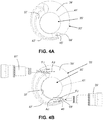
- the outer end 45' of the spiral shaped wall 37' may extend to the peripheral edge 47' of the top 39' of the piston head 33' and the bowl may have no ramp.
- the fuel injectors can be (but is not necessarily) oriented so that the central axis of the injected fuel jet FJ is generally perpendicular to a central axis AC of the cylinder.
- the fuel injectors can, alternatively, be disposed at an angle to the perpendicular, which can further facilitate mixing of gas and fuel by causing the mixture to "tumble" in the sense that, after proceeding downwardly into the bowl 35', it then moves upwardly again, as well as to "swirl” by moving circumferentially around the bowl.
- the spiral shape of the walls 37 and 37' facilitates creation of a circumferential swirling effect in the cylinder 27 and 27' that facilitates mixing of the injected fuel with incoming air and later with scavenging of exhaust gas. While dimensions will vary depending upon factors such as the size of the piston head 33 and cylinder 27, for a fuel jet FJ that is typically about 50 mm in length, the length of the walls 37 and 37' will ordinarily be between about 20 and 100 mm, more preferably between about 30 and 60 mm. In the illustrated embodiments, the circumferential swirling effect will be in the clockwise direction, however, it will be appreciated that the effect could alternatively be in the counter-clockwise direction
- the center portion 41 of the piston bowl 35 is ordinarily substantially circular in shape. This is true, as well, for the embodiment of the piston bowl 35' shown in FIGS. 4A-4B , as illustrated by the dotted line representing the circular central portion 41', however, the circular shape is more apparent in FIGS. 3A-3B .
- the spiral shaped wall 37 typically increases in depth from the outer end 45 of the spiral shaped wall toward an inner end 49 of the spiral shaped wall at the center portion 41.
- substantially circular is defined herein as meaning approximating circular, but not necessarily exactly circular, as the precise boundaries of the substantially circular central portions may not be capable of precise definition as different surfaces merge into each other, or (as in the piston heads 33' shown in FIGS. 4A-4B ) the shapes do not As seen in FIG. 3C (cross-section of piston head), the center portion 41 of the piston bowl 35 can be substantially flat or, as shown in phantom, concave. Altering the depth and total volume of the piston bowl 35 alters the compression ratio that is desired to be obtained by the piston head 33 and cylinder 27.
- the bowl 35 of the piston head 33 is at least partially defined by a second wall 51 having a generally spiral shape.
- the first spiral shaped wall 37 and the second spiral shaped wall 51 are ordinarily rotationally symmetrical about the central axis AC of the cylinder 27.
- a top surface 53 of the top 39 of the piston head 33 is substantially flat, and the piston bowl 35 and the first and second spiral shaped walls 37 and 51 are recessed relative to the top surface.
- First and second recesses 55 and 57 defining outer ends 45 and 59 of the first and second spiral shaped walls 37 and 51, respectively, can be disposed inwardly from an outer peripheral edge 47 of the top 39 of the piston head 33.
- a second fuel injector 61 can also be provided in a second opening 63 in the cylinder wall 25.
- the first and second fuel injectors 29 and 61 can be oriented relative to the piston bowl 35 so that central axes AJ of injected fuel jets FJ from the first and second fuel injectors are generally aligned with centers of the first and second recesses 55 and 57.
- a center portion 41 of the piston bowl 35 is substantially circular in shape, and the first and second fuel injectors 29 and 61 are oriented relative to the piston bowl so that central axes AJ of injected fuel jets FJ from the first and second fuel injectors are offset relative to the central axis of the piston 33 so that they are tangent to the circle, or nearly tangent thereto, as illustrated in FIG. 1 .
- the injectors 29 and 61 are illustrated as being disposed at approximately 180 degrees around the circumference of the cylinder 25 from each other, however, it is possible that the injectors could disposed at different angular relationships. Additionally, although two injectors are shown in the illustrated embodiments, it will be appreciated that one or more than two injectors may be provided in different embodiments.
- a periphery 47' of the top 39' of the piston head is recessed at an outer end 45' of the spiral shaped wall 37', i.e., the spiral shaped wall extends all the way to the periphery of the top of the piston head to define a recess 69'.
- the fuel injectors 29' and 61' are oriented relative to piston bowl 35' so that a central axis AJ of an injected fuel jet FJ is generally aligned with a center of the recess 69'. As seen, for example, in FIGS.
- the piston head 33' is ordinarily used with another upper piston head 33U' in an opposed piston engine 21'.
- the piston head 33' and the upper piston head 33U' will be mirror images of each other, except that one is rotated 180 degrees around a central axis of the cylinder to the other.
- references to the piston head 33' will be understood to apply equally to the piston head 33U', except where otherwise indicated.
- an opposed piston engine 21 using the piston heads 33 shown in FIGS. 1-3C can have the same basic constructions as the opposed piston engine 21' shown in FIGS. 5A-5B .
- the center portion 41' of the resulting piston bowl 35' is more clearly substantially circular in shape.
- the central axis AJ of the injected fuel jet FJ is offset from the central axis of the piston so that it is tangent to, or nearly tangent to, the resulting circle at the center portion 41'.
- the circle 41' defined by the spiral shaped wall 37' of the piston head 33' may be offset from the circle defined by the spiral shaped wall of the upper piston head 33U'.
- the spiral shaped walls 37' of the piston heads 33' and 33U' can be rather high, which can be helpful to avoid spraying fuel on the cylinder wall or liner.
- a second fuel injector 61' can be disposed in a second opening 63' in the cylinder wall 25', and a second piston head 33' can be disposed in the cylinder 27'.
- the second piston head 33' can have a second piston bowl 35' at least partially defined by a second wall 51' having a generally spiral shape in a top 39' of the second piston head.
- the top 39' of the first piston head 33' faces the top of the second piston head.
- the piston heads 33' can be replaced by the piston heads 33 shown in, e.g., FIGS. 1-3C .
- At least one inlet port 71' ordinarily a plurality of inlet ports
- at least one outlet port 73 can be provided in the cylinder wall below a TDC and above a BDC of the second or "lower” piston head 33'.
- references to "above” and “below” when referring to TDC or BDC relate to the positions of the pistons in the cylinder, where TDC will always be considered to be above BDC, regardless of the orientation of the cylinder or the direction of movement of the piston head toward TDC or BDC.
- References to "upper” or “lower” when referring to the two piston heads 33' are only with reference to their positions in the embodiment illustrated, and it will be appreciated that the cylinder 27' can be oriented differently than shown with the inlet ports vertically above the outlet ports, such as where the inlet and outlet ports are horizontally even with each other, the inlet ports are all vertically below the outlet ports, or something in between with some inlet ports being above some outlet ports and some outlet ports being above some inlet ports.
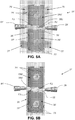
- FIG. 6A which shows a piston head 33 as in FIGS. 1-3C
- the center portions 41 of the first and second piston bowls 35 can be substantially circular in shape, and a central axis AI of the at least one inlet port 71 can be offset relative to the central axis AC of the cylinder 27 and substantially tangent to the center portions of the first and second piston bowls.
- the piston head 33 seen in FIG. 6A would be the lower piston head.
- a central axis AO of the at least one outlet port73 can also be offset relative to the central axis AC of the cylinder 27 and substantially tangent to the center portions 41 of the first and second piston bowls 35.
- the piston head 33 seen in FIG. 6B would also be the lower piston head.
- the inlet ports 71' and outlet ports 73' of the cylinders 27' shown in FIGS. 5A-5B will ordinarily also be oriented in the manner shown in FIGS. 6A and 6B .
- inlet ducts 75' and outlet ducts 77' can extend around the cylinder 27' and lead to each of a plurality of inlet ports 71' and outlet ports 73', respectively.
- the first and second spiral shaped walls 137 and 151 can increase in depth from the outer ends 145 and 159 of the first and second spiral shaped walls toward inner ends 149 and 165 of the first and second spiral shaped walls at a substantially circular center portion 141 of the piston bowl 135.
- the inner ends 149 and 165 of the first and second spiral shaped walls 137 and 151 can merge into an S-shaped partition 167 between two concave portions 141a and 141b of the center portion of the piston bowl.
- the concave portions 141a and 141b form a "yin and yang" geometry when viewed along the central axis of the piston head.
- the concave portions 141a and 141b are generally teardrop shaped in that they increase from a minimal depth at the outer end of the spiral shaped walls to a largest depth close to the inner end of the spiral shaped walls and then back to a zero depth over a relatively short distance. As seen by the arrows reflecting the flow of gas in the concave portions 141a and 141b, this geometry further facilitates mixing of fuel and air by causing the gas and fuel to "tumble" in the sense that, after proceeding downwardly into the bowl 135, it is then caused to move upwardly again, as well as to "swirl” by moving circumferentially around the bowl.
Landscapes
- Engineering & Computer Science (AREA)
- Chemical & Material Sciences (AREA)
- Combustion & Propulsion (AREA)
- Mechanical Engineering (AREA)
- General Engineering & Computer Science (AREA)
- Combustion Methods Of Internal-Combustion Engines (AREA)
Claims (17)
- Chambre de combustion (23) pour un moteur à combustion interne (21), comprenant :une paroi de cylindre (25) définissant un cylindre (27),un premier injecteur de carburant (29) disposé dans une première ouverture dans la paroi de cylindre (25) et un second injecteur de carburant (61) disposé dans une seconde ouverture dans la paroi de cylindre (25) ;une tête de piston (33) disposée dans le cylindre (27), une partie supérieure de la tête de piston (33) étant dotée d'une cuve de piston (35) au moins partiellement définie par une première paroi (37) ayant une forme en spirale et par une seconde paroi (51) ayant une forme en spirale,dans laquelle la première paroi en forme de spirale (37) et la seconde paroi en forme de spirale (51) sont symétriques en rotation autour d'un axe central (AC) du cylindre (27), dans laquelle une partie centrale (41) de la cuve du piston est de forme circulaire, dans laquelle les premier et second injecteurs de carburant (29, 61) sont orientés par rapport à la cuve de piston (35) de telle sorte que les axes centraux de jets de carburant injectés à partir des premier et second injecteurs de carburant (29, 61) sont tangents à la partie centrale (41), dans laquelle la cuve de piston (35) est définie en outre par une rampe (43),caractérisée en ce que la rampe est définie sur un bord par la première paroi en forme de spirale (37) et sur un autre bord par la partie centrale (41) de la cuve de piston (35), dans laquelle la première paroi en forme de spirale (37) augmente en profondeur d'une extrémité externe (45) de la paroi en forme de spirale vers une extrémité interne (49) de la paroi en forme de spirale au niveau de la partie centrale (41).
- Chambre de combustion (23) pour un moteur à combustion interne (21) selon la revendication 1, dans laquelle ladite rampe descend de ladite surface supérieure (53) de la tête de piston (33) jusqu'à ladite partie centrale (41) à une certaine distance en dessous de la surface supérieure (53).
- Chambre de combustion (23) pour un moteur à combustion interne (21) selon la revendication 1, dans laquelle la partie centrale (41) de la cuve de piston (35) est plate.
- Chambre de combustion (23) pour un moteur à combustion interne (21) selon la revendication 1, dans laquelle la partie centrale (41) de la cuve de piston est concave (35).
- Chambre de combustion (23) pour un moteur à combustion interne (21) selon la revendication 1, dans laquelle une surface supérieure (53) de la partie supérieure de la tête de piston est plate, et la cuve de piston (35) et les première et seconde parois en forme de spirale (37, 51) sont en creux par rapport à la surface supérieure.
- Chambre de combustion (23) pour un moteur à combustion interne (21) selon la revendication 5, dans laquelle les premier et second creux (55, 57) définissant les extrémités externes des première et seconde parois en forme de spirale (37, 51) sont disposés vers l'intérieur d'un bord périphérique externe de la partie supérieure de la tête de piston (33).
- Chambre de combustion (23) pour un moteur à combustion interne (21) selon la revendication 6, dans laquelle les premier et second injecteurs de carburant (29, 61) sont orientés par rapport à la cuve de piston (35) de telle sorte que les axes centraux des jets de carburant injectés à partir des premier et second injecteurs de carburant (29, 61) sont alignés avec les centres des premier et second creux (55, 57).
- Chambre de combustion (23) pour un moteur à combustion interne (21) selon la revendication 1, dans laquelle les première et seconde parois en forme de spirale (37, 51) augmentent en profondeur des extrémités externes des première et seconde parois en forme de spirale (37, 51) vers les extrémités internes des première et seconde parois en forme de spirale (37, 51).
- Chambre de combustion (23) pour un moteur à combustion interne (21) selon la revendication 8, dans laquelle les extrémités internes des première et seconde parois en forme de spirale (37, 51) se rejoignent dans une séparation en forme de S entre deux parties concaves de la partie centrale de la cuve de piston (35).
- Chambre de combustion (23) pour un moteur à combustion interne (21) selon la revendication 1, dans laquelle les première et seconde parois en forme de spirale (37, 51) font entre 20 et 100 mm de long.
- Chambre de combustion (23) pour un moteur à combustion interne (21) selon la revendication 1, comprenant une seconde tête de piston (33') disposée dans le cylindre (27), une seconde cuve de piston (35') définie au moins partiellement par une seconde paroi (5) ayant une forme en spirale prévue dans une partie supérieure de la seconde tête de piston (33'), la partie supérieure de la première tête de piston (33) faisant face à la partie supérieure de la seconde tête de piston (33').
- Chambre de combustion (23) pour un moteur à combustion interne (21) selon la revendication 11, dans laquelle la seconde tête de piston (33') est une image miroir de la première tête de piston (33).
- Chambre de combustion (23) pour un moteur à combustion interne (21) selon la revendication 11, comprenant au moins un orifice d'entrée (71') dans la paroi de cylindre (25) en dessous d'un point mort supérieur et au-dessus d'un point mort inférieur de la première tête de piston (33) et au moins un orifice de sortie (73) dans la paroi de cylindre en dessous d'un point mort supérieur et au-dessous d'un point mort inférieur de la seconde tête de piston (33').
- Chambre de combustion (23) pour un moteur à combustion interne (21) selon la revendication 13, dans laquelle les parties centrales des première et seconde cuves de piston ont une forme circulaire, et un axe central de l'au moins un orifice d'entrée est décalé par rapport à l'axe central du cylindre (27) et sensiblement tangent aux parties centrales des première et seconde cuves de piston.
- Chambre de combustion (23) pour un moteur à combustion interne (21) selon la revendication 14, dans laquelle un axe central de l'au moins un orifice de sortie est décalé par rapport à l'axe central du cylindre (27) et sensiblement tangent aux parties centrales des première et seconde cuves de piston (35, 35').
- Chambre de combustion (23) pour un moteur à combustion interne (21) selon la revendication 13, dans laquelle les parties centrales des première et seconde cuves de piston ont une forme sensiblement circulaire, et un axe central de l'au moins un orifice de sortie est décalé par rapport à l'axe central du cylindre et sensiblement tangent aux parties centrales des première et seconde cuves de piston (35, 35').
- Moteur à combustion interne (21) comprenant une chambre de combustion (23) selon la revendication 1.
Applications Claiming Priority (1)
| Application Number | Priority Date | Filing Date | Title |
|---|---|---|---|
| PCT/US2014/035773 WO2015167444A1 (fr) | 2014-04-29 | 2014-04-29 | Chambre de combustion pour moteur à combustion interne, et moteur à combustion interne |
Publications (3)
| Publication Number | Publication Date |
|---|---|
| EP3140527A1 EP3140527A1 (fr) | 2017-03-15 |
| EP3140527A4 EP3140527A4 (fr) | 2017-12-27 |
| EP3140527B1 true EP3140527B1 (fr) | 2020-11-18 |
Family
ID=54359003
Family Applications (1)
| Application Number | Title | Priority Date | Filing Date |
|---|---|---|---|
| EP14890716.5A Active EP3140527B1 (fr) | 2014-04-29 | 2014-04-29 | Chambre de combustion pour moteur à combustion interne, et moteur à combustion interne |
Country Status (3)
| Country | Link |
|---|---|
| US (1) | US10415456B2 (fr) |
| EP (1) | EP3140527B1 (fr) |
| WO (1) | WO2015167444A1 (fr) |
Families Citing this family (8)
| Publication number | Priority date | Publication date | Assignee | Title |
|---|---|---|---|---|
| US9995213B2 (en) * | 2015-03-31 | 2018-06-12 | Achates Power, Inc. | Asymmetrically-shaped combustion chamber for opposed-piston engines |
| EP3176403A1 (fr) * | 2015-12-02 | 2017-06-07 | Caterpillar Energy Solutions GmbH | Piston pour un moteur à combustion interne à combustible gazeux |
| US9995203B2 (en) * | 2016-10-27 | 2018-06-12 | Caterpillar Inc. | Piston design for flow re-direction |
| WO2019050804A1 (fr) * | 2017-09-07 | 2019-03-14 | Achates Power, Inc. | Ensemble piston pourvu de zones d'injection opposées pour un moteur à pistons opposés |
| US10876495B2 (en) * | 2018-10-11 | 2020-12-29 | Caterpillar Inc. | Piston design for splitting jets into streams |
| US11555469B2 (en) * | 2020-06-29 | 2023-01-17 | Cummins Inc. | Piston bowls |
| US11959436B2 (en) * | 2022-09-20 | 2024-04-16 | Tenneco Inc. | Piston including spiral features to increase in-cylinder swirl |
| JP2025110666A (ja) * | 2024-01-16 | 2025-07-29 | 三菱重工業株式会社 | 対向ピストンエンジン |
Citations (1)
| Publication number | Priority date | Publication date | Assignee | Title |
|---|---|---|---|---|
| US20130014718A1 (en) * | 2011-07-15 | 2013-01-17 | Ecomotors International, Inc. | Toroidal Combustion Chamber With Side Injection |
Family Cites Families (44)
| Publication number | Priority date | Publication date | Assignee | Title |
|---|---|---|---|---|
| SE102658C1 (fr) * | ||||
| US1856328A (en) * | 1926-11-24 | 1932-05-03 | Louis O French | Internal combustion engine |
| US2231392A (en) * | 1939-01-26 | 1941-02-11 | John J Mccarthy | Internal combustion engine |
| US2269084A (en) * | 1941-05-03 | 1942-01-06 | John J Mccarthy | Internal combustion engine |
| US2504036A (en) * | 1945-08-24 | 1950-04-11 | Morrison Alfred Charles | Combustion chamber for internal-combustion engines |
| US2600440A (en) * | 1950-05-17 | 1952-06-17 | Donald H Smith | Piston construction for internal-combustion engines |
| US2766738A (en) * | 1953-07-24 | 1956-10-16 | Daimler Benz Ag | Internal combustion engine |
| US2851019A (en) * | 1956-06-29 | 1958-09-09 | Gen Motors Corp | Combustion chamber for internal combustion engine |
| DE1451636A1 (de) * | 1963-09-21 | 1969-07-10 | Daimler Benz Ag | Dieselmotor,insbesondere Viertaktmotor fuer Kraftfahrzeuge |
| GB1293855A (en) * | 1969-05-24 | 1972-10-25 | Daimler Benz Ag | Four-stroke internal combustion engines |
| JPS5949407B2 (ja) * | 1976-11-15 | 1984-12-03 | トヨタ自動車株式会社 | 内燃機関の燃焼室 |
| JPS57171026A (en) * | 1981-04-16 | 1982-10-21 | Nippon Soken Inc | Direct injection type diesel engine |
| US4467752A (en) * | 1982-06-21 | 1984-08-28 | Motortech, Inc. | Internal combustion engine |
| JPS6314836U (fr) * | 1986-07-14 | 1988-01-30 | ||
| DE3629437A1 (de) * | 1986-08-29 | 1988-03-03 | Elsbett L | Brennstoffeinspritzung fuer kolbenbrennkraftmaschine mit mehreren einspritzduesen |
| JPS63113113A (ja) * | 1986-10-31 | 1988-05-18 | Matsukichi Haruyama | 内燃機関のピストン構造 |
| US5103784A (en) * | 1990-02-07 | 1992-04-14 | The Univeristy Of British Columbia | Squish jet combustion chamber |
| US5065715A (en) * | 1990-02-07 | 1991-11-19 | The University Of British Columbia | Squish jet combustion chamber |
| JPH084535A (ja) * | 1994-06-17 | 1996-01-09 | Kubota Corp | 直接噴射式ディーゼルエンジンのピストン |
| US6003487A (en) * | 1995-08-05 | 1999-12-21 | Merritt; Dan | Internal combustion engine |
| AT2432U1 (de) * | 1997-10-16 | 1998-10-27 | Avl List Gmbh | Brennkraftmaschine mit fremdzündung |
| JP3767125B2 (ja) * | 1997-10-21 | 2006-04-19 | 日産自動車株式会社 | 筒内噴射式内燃機関のピストン |
| US6182619B1 (en) * | 1998-12-24 | 2001-02-06 | General Atomics Aeronautical Systems, Inc. | Two-stroke diesel engine |
| AUPQ092199A0 (en) * | 1999-06-14 | 1999-07-01 | Aardvark Pty. Ltd. | Internal combustion engine |
| JP4149621B2 (ja) * | 1999-09-03 | 2008-09-10 | 邦彦 奥平 | 対向ピストン式2サイクルユニフロー型機関 |
| DE19957461A1 (de) * | 1999-11-29 | 2001-06-07 | Adolf Filmann | Drallkanäle für Verbrennungsmotore - Brennraum |
| US6418885B1 (en) * | 2000-03-17 | 2002-07-16 | Marius A. Paul | Total energy general optimized engine cycle |
| US6609490B2 (en) | 2001-11-15 | 2003-08-26 | John Flinchbaugh | Piston head for a spark ignition engine |
| US7360511B2 (en) * | 2004-06-10 | 2008-04-22 | Achates Power, Inc. | Opposed piston engine |
| JP4100401B2 (ja) * | 2005-02-24 | 2008-06-11 | トヨタ自動車株式会社 | 内燃機関 |
| US8561581B2 (en) * | 2009-08-04 | 2013-10-22 | Jack R. Taylor | Two-stroke uniflow turbo-compound internal combustion engine |
| US20110067671A1 (en) * | 2009-09-01 | 2011-03-24 | Laimboeck Franz J | Non-soot emitting fuel combustion chamber |
| EP2501911A1 (fr) * | 2009-11-18 | 2012-09-26 | Achates Power, Inc. | Appareil et procédé de contrôle des tourbillons dans un moteur à combustion interne deux temps à lumières |
| DE202009017699U1 (de) * | 2009-11-18 | 2010-09-23 | Daude, Otto, Dr.-Ing. MBA | Tangential am Zylinderumfang ausgerichtete Einspritzdüsen für Verbrennungsmotoren mit Gaswechselsteuerung |
| US20110186017A1 (en) * | 2010-02-03 | 2011-08-04 | Achates Power, Inc. | Single-crankshaft, opposed-piston engine constructions |
| US10180115B2 (en) * | 2010-04-27 | 2019-01-15 | Achates Power, Inc. | Piston crown bowls defining combustion chamber constructions in opposed-piston engines |
| US9512779B2 (en) * | 2010-04-27 | 2016-12-06 | Achates Power, Inc. | Swirl-conserving combustion chamber construction for opposed-piston engines |
| WO2011139332A2 (fr) * | 2010-04-27 | 2011-11-10 | Achates Power, Inc. | Types de chambre de combustion pour moteurs à pistons opposés |
| EP2998541B1 (fr) | 2010-08-16 | 2017-01-04 | Achates Power, Inc. | Motifs de pulvérisation d'injection de carburant pour moteurs à pistons opposés |
| US9309807B2 (en) * | 2011-05-18 | 2016-04-12 | Achates Power, Inc. | Combustion chamber constructions for opposed-piston engines |
| GB2493260A (en) | 2011-07-26 | 2013-01-30 | Ecomotors Internat Inc | Opposed piston engine with tumble flow in shaped combustion chamber |
| US20130036999A1 (en) | 2011-08-08 | 2013-02-14 | Ecomotors International, Inc. | High-Squish Combustion Chamber With Side Injection |
| GB2496479A (en) * | 2011-11-11 | 2013-05-15 | Ecomotors Internat Inc | Intake System for an Opposed-Piston Engine |
| DE102012111776A1 (de) * | 2011-12-09 | 2013-06-13 | Ecomotors International, Inc. | Gegenkolbenmotor mit ringförmiger Brennkammer mit Seiteneinspritzung |
-
2014
- 2014-04-29 US US15/303,000 patent/US10415456B2/en active Active
- 2014-04-29 WO PCT/US2014/035773 patent/WO2015167444A1/fr not_active Ceased
- 2014-04-29 EP EP14890716.5A patent/EP3140527B1/fr active Active
Patent Citations (1)
| Publication number | Priority date | Publication date | Assignee | Title |
|---|---|---|---|---|
| US20130014718A1 (en) * | 2011-07-15 | 2013-01-17 | Ecomotors International, Inc. | Toroidal Combustion Chamber With Side Injection |
Also Published As
| Publication number | Publication date |
|---|---|
| US10415456B2 (en) | 2019-09-17 |
| EP3140527A1 (fr) | 2017-03-15 |
| EP3140527A4 (fr) | 2017-12-27 |
| US20170067391A1 (en) | 2017-03-09 |
| WO2015167444A1 (fr) | 2015-11-05 |
Similar Documents
| Publication | Publication Date | Title |
|---|---|---|
| US10415456B2 (en) | Combustion chamber for an internal combustion engine and an internal combustion engine | |
| US20130036999A1 (en) | High-Squish Combustion Chamber With Side Injection | |
| US9482145B2 (en) | Toroidal combustion chamber with side injection | |
| US8783218B2 (en) | Toroidal combustion chamber with side injection | |
| US9211797B2 (en) | Combustion chamber construction with dual mixing regions for opposed-piston engines | |
| JP6818011B2 (ja) | 対向ピストンエンジンのための歪み形燃焼室 | |
| CN103842618B (zh) | 内燃机 | |
| US10309294B2 (en) | Engine | |
| US11053838B2 (en) | Combustion chamber geometry | |
| US20160252067A1 (en) | Opposed Piston Three Nozzle Piston Bowl Design | |
| CN105829676A (zh) | 用于对置活塞发动机的漩涡保存燃烧室结构 | |
| EP3176402B1 (fr) | Piston pour un moteur à combustion interne à combustible gazeux | |
| JP2009047070A (ja) | 筒内噴射式火花点火内燃機関 | |
| US11408367B2 (en) | Internal combustion engine | |
| JPH03182621A (ja) | 内燃機関 | |
| CN109751114B (zh) | 内燃机的燃烧室结构 | |
| JP6398700B2 (ja) | 筒内噴射式エンジン | |
| JP6476841B2 (ja) | 筒内噴射式エンジン用ピストン | |
| CN108260358B (zh) | 具有开槽式顶部槽脊的发动机活塞 | |
| JP3684679B2 (ja) | 内燃機関用ピストン | |
| EP3176403A1 (fr) | Piston pour un moteur à combustion interne à combustible gazeux | |
| CN105736123A (zh) | 缸内喷射式发动机用活塞 | |
| JP4075471B2 (ja) | 筒内直接噴射式内燃機関 | |
| US10280831B2 (en) | Engine | |
| JPH0112925B2 (fr) |
Legal Events
| Date | Code | Title | Description |
|---|---|---|---|
| STAA | Information on the status of an ep patent application or granted ep patent |
Free format text: STATUS: THE INTERNATIONAL PUBLICATION HAS BEEN MADE |
|
| PUAI | Public reference made under article 153(3) epc to a published international application that has entered the european phase |
Free format text: ORIGINAL CODE: 0009012 |
|
| STAA | Information on the status of an ep patent application or granted ep patent |
Free format text: STATUS: REQUEST FOR EXAMINATION WAS MADE |
|
| 17P | Request for examination filed |
Effective date: 20161124 |
|
| AK | Designated contracting states |
Kind code of ref document: A1 Designated state(s): AL AT BE BG CH CY CZ DE DK EE ES FI FR GB GR HR HU IE IS IT LI LT LU LV MC MK MT NL NO PL PT RO RS SE SI SK SM TR |
|
| AX | Request for extension of the european patent |
Extension state: BA ME |
|
| DAX | Request for extension of the european patent (deleted) | ||
| A4 | Supplementary search report drawn up and despatched |
Effective date: 20171124 |
|
| RIC1 | Information provided on ipc code assigned before grant |
Ipc: F02B 23/06 20060101AFI20171120BHEP |
|
| STAA | Information on the status of an ep patent application or granted ep patent |
Free format text: STATUS: EXAMINATION IS IN PROGRESS |
|
| 17Q | First examination report despatched |
Effective date: 20180704 |
|
| GRAP | Despatch of communication of intention to grant a patent |
Free format text: ORIGINAL CODE: EPIDOSNIGR1 |
|
| STAA | Information on the status of an ep patent application or granted ep patent |
Free format text: STATUS: GRANT OF PATENT IS INTENDED |
|
| INTG | Intention to grant announced |
Effective date: 20200117 |
|
| GRAS | Grant fee paid |
Free format text: ORIGINAL CODE: EPIDOSNIGR3 |
|
| GRAJ | Information related to disapproval of communication of intention to grant by the applicant or resumption of examination proceedings by the epo deleted |
Free format text: ORIGINAL CODE: EPIDOSDIGR1 |
|
| GRAL | Information related to payment of fee for publishing/printing deleted |
Free format text: ORIGINAL CODE: EPIDOSDIGR3 |
|
| STAA | Information on the status of an ep patent application or granted ep patent |
Free format text: STATUS: EXAMINATION IS IN PROGRESS |
|
| INTC | Intention to grant announced (deleted) | ||
| GRAP | Despatch of communication of intention to grant a patent |
Free format text: ORIGINAL CODE: EPIDOSNIGR1 |
|
| STAA | Information on the status of an ep patent application or granted ep patent |
Free format text: STATUS: GRANT OF PATENT IS INTENDED |
|
| INTG | Intention to grant announced |
Effective date: 20200617 |
|
| GRAS | Grant fee paid |
Free format text: ORIGINAL CODE: EPIDOSNIGR3 |
|
| GRAA | (expected) grant |
Free format text: ORIGINAL CODE: 0009210 |
|
| STAA | Information on the status of an ep patent application or granted ep patent |
Free format text: STATUS: THE PATENT HAS BEEN GRANTED |
|
| AK | Designated contracting states |
Kind code of ref document: B1 Designated state(s): AL AT BE BG CH CY CZ DE DK EE ES FI FR GB GR HR HU IE IS IT LI LT LU LV MC MK MT NL NO PL PT RO RS SE SI SK SM TR |
|
| REG | Reference to a national code |
Ref country code: GB Ref legal event code: FG4D |
|
| REG | Reference to a national code |
Ref country code: CH Ref legal event code: EP |
|
| REG | Reference to a national code |
Ref country code: DE Ref legal event code: R096 Ref document number: 602014072587 Country of ref document: DE |
|
| REG | Reference to a national code |
Ref country code: IE Ref legal event code: FG4D |
|
| REG | Reference to a national code |
Ref country code: AT Ref legal event code: REF Ref document number: 1336022 Country of ref document: AT Kind code of ref document: T Effective date: 20201215 |
|
| REG | Reference to a national code |
Ref country code: AT Ref legal event code: MK05 Ref document number: 1336022 Country of ref document: AT Kind code of ref document: T Effective date: 20201118 |
|
| REG | Reference to a national code |
Ref country code: NL Ref legal event code: MP Effective date: 20201118 |
|
| PG25 | Lapsed in a contracting state [announced via postgrant information from national office to epo] |
Ref country code: GR Free format text: LAPSE BECAUSE OF FAILURE TO SUBMIT A TRANSLATION OF THE DESCRIPTION OR TO PAY THE FEE WITHIN THE PRESCRIBED TIME-LIMIT Effective date: 20210219 Ref country code: NO Free format text: LAPSE BECAUSE OF FAILURE TO SUBMIT A TRANSLATION OF THE DESCRIPTION OR TO PAY THE FEE WITHIN THE PRESCRIBED TIME-LIMIT Effective date: 20210218 Ref country code: PT Free format text: LAPSE BECAUSE OF FAILURE TO SUBMIT A TRANSLATION OF THE DESCRIPTION OR TO PAY THE FEE WITHIN THE PRESCRIBED TIME-LIMIT Effective date: 20210318 Ref country code: FI Free format text: LAPSE BECAUSE OF FAILURE TO SUBMIT A TRANSLATION OF THE DESCRIPTION OR TO PAY THE FEE WITHIN THE PRESCRIBED TIME-LIMIT Effective date: 20201118 Ref country code: RS Free format text: LAPSE BECAUSE OF FAILURE TO SUBMIT A TRANSLATION OF THE DESCRIPTION OR TO PAY THE FEE WITHIN THE PRESCRIBED TIME-LIMIT Effective date: 20201118 |
|
| PG25 | Lapsed in a contracting state [announced via postgrant information from national office to epo] |
Ref country code: AT Free format text: LAPSE BECAUSE OF FAILURE TO SUBMIT A TRANSLATION OF THE DESCRIPTION OR TO PAY THE FEE WITHIN THE PRESCRIBED TIME-LIMIT Effective date: 20201118 Ref country code: BG Free format text: LAPSE BECAUSE OF FAILURE TO SUBMIT A TRANSLATION OF THE DESCRIPTION OR TO PAY THE FEE WITHIN THE PRESCRIBED TIME-LIMIT Effective date: 20210218 Ref country code: PL Free format text: LAPSE BECAUSE OF FAILURE TO SUBMIT A TRANSLATION OF THE DESCRIPTION OR TO PAY THE FEE WITHIN THE PRESCRIBED TIME-LIMIT Effective date: 20201118 Ref country code: IS Free format text: LAPSE BECAUSE OF FAILURE TO SUBMIT A TRANSLATION OF THE DESCRIPTION OR TO PAY THE FEE WITHIN THE PRESCRIBED TIME-LIMIT Effective date: 20210318 Ref country code: SE Free format text: LAPSE BECAUSE OF FAILURE TO SUBMIT A TRANSLATION OF THE DESCRIPTION OR TO PAY THE FEE WITHIN THE PRESCRIBED TIME-LIMIT Effective date: 20201118 Ref country code: LV Free format text: LAPSE BECAUSE OF FAILURE TO SUBMIT A TRANSLATION OF THE DESCRIPTION OR TO PAY THE FEE WITHIN THE PRESCRIBED TIME-LIMIT Effective date: 20201118 |
|
| REG | Reference to a national code |
Ref country code: LT Ref legal event code: MG9D |
|
| PG25 | Lapsed in a contracting state [announced via postgrant information from national office to epo] |
Ref country code: HR Free format text: LAPSE BECAUSE OF FAILURE TO SUBMIT A TRANSLATION OF THE DESCRIPTION OR TO PAY THE FEE WITHIN THE PRESCRIBED TIME-LIMIT Effective date: 20201118 |
|
| PG25 | Lapsed in a contracting state [announced via postgrant information from national office to epo] |
Ref country code: SM Free format text: LAPSE BECAUSE OF FAILURE TO SUBMIT A TRANSLATION OF THE DESCRIPTION OR TO PAY THE FEE WITHIN THE PRESCRIBED TIME-LIMIT Effective date: 20201118 Ref country code: EE Free format text: LAPSE BECAUSE OF FAILURE TO SUBMIT A TRANSLATION OF THE DESCRIPTION OR TO PAY THE FEE WITHIN THE PRESCRIBED TIME-LIMIT Effective date: 20201118 Ref country code: CZ Free format text: LAPSE BECAUSE OF FAILURE TO SUBMIT A TRANSLATION OF THE DESCRIPTION OR TO PAY THE FEE WITHIN THE PRESCRIBED TIME-LIMIT Effective date: 20201118 Ref country code: SK Free format text: LAPSE BECAUSE OF FAILURE TO SUBMIT A TRANSLATION OF THE DESCRIPTION OR TO PAY THE FEE WITHIN THE PRESCRIBED TIME-LIMIT Effective date: 20201118 Ref country code: RO Free format text: LAPSE BECAUSE OF FAILURE TO SUBMIT A TRANSLATION OF THE DESCRIPTION OR TO PAY THE FEE WITHIN THE PRESCRIBED TIME-LIMIT Effective date: 20201118 Ref country code: LT Free format text: LAPSE BECAUSE OF FAILURE TO SUBMIT A TRANSLATION OF THE DESCRIPTION OR TO PAY THE FEE WITHIN THE PRESCRIBED TIME-LIMIT Effective date: 20201118 |
|
| REG | Reference to a national code |
Ref country code: DE Ref legal event code: R097 Ref document number: 602014072587 Country of ref document: DE |
|
| PG25 | Lapsed in a contracting state [announced via postgrant information from national office to epo] |
Ref country code: DK Free format text: LAPSE BECAUSE OF FAILURE TO SUBMIT A TRANSLATION OF THE DESCRIPTION OR TO PAY THE FEE WITHIN THE PRESCRIBED TIME-LIMIT Effective date: 20201118 |
|
| PLBE | No opposition filed within time limit |
Free format text: ORIGINAL CODE: 0009261 |
|
| STAA | Information on the status of an ep patent application or granted ep patent |
Free format text: STATUS: NO OPPOSITION FILED WITHIN TIME LIMIT |
|
| 26N | No opposition filed |
Effective date: 20210819 |
|
| PG25 | Lapsed in a contracting state [announced via postgrant information from national office to epo] |
Ref country code: IT Free format text: LAPSE BECAUSE OF FAILURE TO SUBMIT A TRANSLATION OF THE DESCRIPTION OR TO PAY THE FEE WITHIN THE PRESCRIBED TIME-LIMIT Effective date: 20201118 Ref country code: NL Free format text: LAPSE BECAUSE OF FAILURE TO SUBMIT A TRANSLATION OF THE DESCRIPTION OR TO PAY THE FEE WITHIN THE PRESCRIBED TIME-LIMIT Effective date: 20201118 Ref country code: AL Free format text: LAPSE BECAUSE OF FAILURE TO SUBMIT A TRANSLATION OF THE DESCRIPTION OR TO PAY THE FEE WITHIN THE PRESCRIBED TIME-LIMIT Effective date: 20201118 |
|
| PG25 | Lapsed in a contracting state [announced via postgrant information from national office to epo] |
Ref country code: MC Free format text: LAPSE BECAUSE OF FAILURE TO SUBMIT A TRANSLATION OF THE DESCRIPTION OR TO PAY THE FEE WITHIN THE PRESCRIBED TIME-LIMIT Effective date: 20201118 Ref country code: ES Free format text: LAPSE BECAUSE OF FAILURE TO SUBMIT A TRANSLATION OF THE DESCRIPTION OR TO PAY THE FEE WITHIN THE PRESCRIBED TIME-LIMIT Effective date: 20201118 Ref country code: SI Free format text: LAPSE BECAUSE OF FAILURE TO SUBMIT A TRANSLATION OF THE DESCRIPTION OR TO PAY THE FEE WITHIN THE PRESCRIBED TIME-LIMIT Effective date: 20201118 |
|
| GBPC | Gb: european patent ceased through non-payment of renewal fee |
Effective date: 20210429 |
|
| PG25 | Lapsed in a contracting state [announced via postgrant information from national office to epo] |
Ref country code: LU Free format text: LAPSE BECAUSE OF NON-PAYMENT OF DUE FEES Effective date: 20210429 |
|
| REG | Reference to a national code |
Ref country code: BE Ref legal event code: MM Effective date: 20210430 |
|
| PG25 | Lapsed in a contracting state [announced via postgrant information from national office to epo] |
Ref country code: CH Free format text: LAPSE BECAUSE OF NON-PAYMENT OF DUE FEES Effective date: 20210430 Ref country code: LI Free format text: LAPSE BECAUSE OF NON-PAYMENT OF DUE FEES Effective date: 20210430 Ref country code: FR Free format text: LAPSE BECAUSE OF NON-PAYMENT OF DUE FEES Effective date: 20210430 Ref country code: GB Free format text: LAPSE BECAUSE OF NON-PAYMENT OF DUE FEES Effective date: 20210429 |
|
| PG25 | Lapsed in a contracting state [announced via postgrant information from national office to epo] |
Ref country code: IE Free format text: LAPSE BECAUSE OF NON-PAYMENT OF DUE FEES Effective date: 20210429 |
|
| PG25 | Lapsed in a contracting state [announced via postgrant information from national office to epo] |
Ref country code: IS Free format text: LAPSE BECAUSE OF FAILURE TO SUBMIT A TRANSLATION OF THE DESCRIPTION OR TO PAY THE FEE WITHIN THE PRESCRIBED TIME-LIMIT Effective date: 20210318 |
|
| PG25 | Lapsed in a contracting state [announced via postgrant information from national office to epo] |
Ref country code: BE Free format text: LAPSE BECAUSE OF NON-PAYMENT OF DUE FEES Effective date: 20210430 |
|
| PG25 | Lapsed in a contracting state [announced via postgrant information from national office to epo] |
Ref country code: HU Free format text: LAPSE BECAUSE OF FAILURE TO SUBMIT A TRANSLATION OF THE DESCRIPTION OR TO PAY THE FEE WITHIN THE PRESCRIBED TIME-LIMIT; INVALID AB INITIO Effective date: 20140429 |
|
| PG25 | Lapsed in a contracting state [announced via postgrant information from national office to epo] |
Ref country code: CY Free format text: LAPSE BECAUSE OF FAILURE TO SUBMIT A TRANSLATION OF THE DESCRIPTION OR TO PAY THE FEE WITHIN THE PRESCRIBED TIME-LIMIT Effective date: 20201118 |
|
| PG25 | Lapsed in a contracting state [announced via postgrant information from national office to epo] |
Ref country code: MK Free format text: LAPSE BECAUSE OF FAILURE TO SUBMIT A TRANSLATION OF THE DESCRIPTION OR TO PAY THE FEE WITHIN THE PRESCRIBED TIME-LIMIT Effective date: 20201118 |
|
| PG25 | Lapsed in a contracting state [announced via postgrant information from national office to epo] |
Ref country code: TR Free format text: LAPSE BECAUSE OF FAILURE TO SUBMIT A TRANSLATION OF THE DESCRIPTION OR TO PAY THE FEE WITHIN THE PRESCRIBED TIME-LIMIT Effective date: 20201118 |
|
| PG25 | Lapsed in a contracting state [announced via postgrant information from national office to epo] |
Ref country code: MT Free format text: LAPSE BECAUSE OF FAILURE TO SUBMIT A TRANSLATION OF THE DESCRIPTION OR TO PAY THE FEE WITHIN THE PRESCRIBED TIME-LIMIT Effective date: 20201118 |
|
| PGFP | Annual fee paid to national office [announced via postgrant information from national office to epo] |
Ref country code: DE Payment date: 20250428 Year of fee payment: 12 |