EP3140612B1 - Fünfachsiges optisches untersuchungssystem - Google Patents
Fünfachsiges optisches untersuchungssystem Download PDFInfo
- Publication number
- EP3140612B1 EP3140612B1 EP15790010.1A EP15790010A EP3140612B1 EP 3140612 B1 EP3140612 B1 EP 3140612B1 EP 15790010 A EP15790010 A EP 15790010A EP 3140612 B1 EP3140612 B1 EP 3140612B1
- Authority
- EP
- European Patent Office
- Prior art keywords
- axis
- camera
- inspection system
- optical
- light source
- Prior art date
- Legal status (The legal status is an assumption and is not a legal conclusion. Google has not performed a legal analysis and makes no representation as to the accuracy of the status listed.)
- Active
Links
Images

Classifications
-
- G—PHYSICS
- G02—OPTICS
- G02B—OPTICAL ELEMENTS, SYSTEMS OR APPARATUS
- G02B21/00—Microscopes
- G02B21/24—Base structure
- G02B21/26—Stages; Adjusting means therefor
-
- G—PHYSICS
- G02—OPTICS
- G02B—OPTICAL ELEMENTS, SYSTEMS OR APPARATUS
- G02B21/00—Microscopes
- G02B21/0004—Microscopes specially adapted for specific applications
- G02B21/0016—Technical microscopes, e.g. for inspection or measuring in industrial production processes
-
- G—PHYSICS
- G02—OPTICS
- G02B—OPTICAL ELEMENTS, SYSTEMS OR APPARATUS
- G02B21/00—Microscopes
- G02B21/36—Microscopes arranged for photographic purposes or projection purposes or digital imaging or video purposes including associated control and data processing arrangements
- G02B21/362—Mechanical details, e.g. mountings for the camera or image sensor, housings
-
- G—PHYSICS
- G02—OPTICS
- G02B—OPTICAL ELEMENTS, SYSTEMS OR APPARATUS
- G02B21/00—Microscopes
- G02B21/36—Microscopes arranged for photographic purposes or projection purposes or digital imaging or video purposes including associated control and data processing arrangements
- G02B21/365—Control or image processing arrangements for digital or video microscopes
- G02B21/367—Control or image processing arrangements for digital or video microscopes providing an output produced by processing a plurality of individual source images, e.g. image tiling, montage, composite images, depth sectioning, image comparison
-
- H—ELECTRICITY
- H04—ELECTRIC COMMUNICATION TECHNIQUE
- H04N—PICTORIAL COMMUNICATION, e.g. TELEVISION
- H04N23/00—Cameras or camera modules comprising electronic image sensors; Control thereof
- H04N23/56—Cameras or camera modules comprising electronic image sensors; Control thereof provided with illuminating means
Definitions
- optical inspection systems for enlarging views of a part or component.
- Such optical inspection systems are known from US2010014747 , US20120105576 and WO9962263 .
- optical inspection systems operate nicely in a three axis configuration.
- the X and Y axes are used to position the workpiece relative to a camera or a sensor and a Z axis provides focus.
- the camera used with an optical inspection system needs to be aimed squarely at the feature to be inspected or parallax imaging distortions will cause measurement errors.
- a part For workpieces that are generally cylindrical, like a medical stent or a machined piston, mounting the part on a rotary or fourth axis provides the camera with a straight on view of any area of the part.
- a part has complex contours like, for example, a bullet, obtaining a high resolution image at each point on the surface while aiming the camera normal to a surface patch requires a five axis of motion optical inspection system.
- An alternative approach to the fifth tilting axis is to mount the camera and lens components of the inspection system on a rotational stage which is in-turn attached to a Z-axis.
- One drawback with this approach is that increased mass is added to one of the existing stage axes.
- a further drawback is that the length of the optical track from object to image at the camera must be accommodated by the stage travel of the system. This can add significant size and cost to the system.
- An object disclosed herein is to provide a system to create high-resolution images of parts with complex contours at high speed and with a minimum of stage travel and overall system size. It is a further goal to provide uniform illumination of the object under inspection both using both profile and surface illumination.
- an inspection system as defined in claim 1.
- the system described herein includes a conventional X,Y,Z three orthogonal axes of motion stage 10.
- a fourth axis is introduced, as is known from four axis inspection systems, that is driven by a motor 11 mounted on the X or Y stage axis with the part 7.
- a four axis system is disclosed in U.S. Pat. No. 8,811,691 , titled "Stent Inspection System,” by Freifeld. The disclosure of U.S. Pat. No. 8,811,691 is incorporated by reference herein in its entirety.
- a key feature of the present embodiment is to locate the optical axis of the lens and camera 1 for viewing part 7 features mounted as is commonly found on traditional machines on the Z-axis 14 with the optical axis substantially parallel to the Z-axis 18.
- a computer numerically controlled right angle reflector 15 is then utilized to bend the traditionally downward facing optical axis 16 by 90 degrees and a motor 3 to drive this right angle beam splitter cube 6 to point outward to the part 7.
- the entire camera 1, lens 4 and right angle reflector 15 are all rotated by the fifth axis of motion motor 3 about the primary optical axis 16.
- the immediate advantage of this method is that the mass of the reflector 15 and, optionally, the mass of the lens 4 and camera 1 are being rotated about their own center of mass thus keeping the moment inertia to a minimum and the space taken in the system stage layout to a minimum as well. This allows for high-speed motion with fast mechanical settling times.
- this fifth axis configuration can be minimized mechanically by configuring the optical axis 16 to be on center and within the fifth axis motor 3, so long as a motor 3 with a hollow shaft 19 of sufficient diameter to allow the full optical path of the system to propagate without vignetting is provided. If the lens 4 is telecentric, the optical system is well disposed for gauging applications.
- illumination can be introduced to the part through the beamsplitter 6 with the right angle reflector 15 being a partially reflective mirror.
- Introducing bright field illumination via light source 5 has advantages over traditional epi-illumination or through the objective lens surface illumination. First, this simplifies the optical configuration. In the more traditional configuration a beamsplitter cube must be placed in a collimated space between the first lens objective and a camera relay lens. This increases the size and complexity of the optical system and tends to introduce stray illumination into the camera, softening the image.
- illumination introduced at the beamsplitter cube below the primary objective can cover a wider angle of illumination as it is not limited by the coverage angle as defined by the numerical aperture of the lens. This can provide a more broadly illuminated object improving image quality. Adding a ring light 9 in front of the beam splitter 6 as a dark field source of illumination can provide an especially broad coverage of illumination. Alternatively, if light is not desired to be directed onto the part from behind the beamsplitter 6, a simple mirror instead of a more elaborate beam splitter cube. The two light sources on either side of the partially reflecting mirror can be operated either individually or simultaneously to create a large area of combined dark and bright field illumination coverage
- a further approach is to add a large area camera 13 and lens 12 to obtain a rotational or a flat scan of the part 7 under inspection.
- the large area camera 13 is a line scan camera. From these large area views the positions of features to be inspected by the fifth axis camera 1 can be more easily determined in spatial coordinates then strictly by driving the fifth axis through a series of predetermined computer numerically controlled moves. This is especially helpful when inspecting parts that are not completely rigid as features are not always where one might expect them based on their design model.
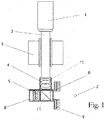
- Figure 1 schematically illustrates a fifth axis viewer.
- a camera 1 views an object 7 through a tube 2, a lens 4 and finally a beamsplitter cube 6.
- the entire optical system is rotated about a portion of the optical axis 16 by motor 3.
- the viewer module 8 has an internal light source 5 positioned so its light shines through the beamsplitter cube 6 and onto the object 7 under inspection.
- a ring light 9 is added in front of the beam splitter cube so that its light also hits the object 7.
- Figure 2 schematically illustrates a full view of a five axis inspection system containing the right angle fifth axis viewer 8 driven by a rotating motor 3 to capture images of object 7 in any angular orientation by camera 1.
- the part 7 under inspection is mounted on a rotary motor stage 11, the fourth axis of the system, which in turn is mounted to a three axis linear positioning stage 10.
- the system also contains a lens 12 having an extended depth of focus of 5mm or more that is used for taking flat or rotational large area images of the part 7 using a line scan camera 13.
- the inspection system includes a digital camera and a lens defining an optical axis. There is a partial mirror below, the lens redirecting the optical axis 90 degrees to view an object.
- An extended area light source is placed behind and configured to direct light through said partial mirror to provided extended bright field illumination on said object with a broad angle of coverage.
- the inspection system light source includes light emitting diodes and the partial mirror is a beam splitter cube.
Landscapes
- Physics & Mathematics (AREA)
- Chemical & Material Sciences (AREA)
- Analytical Chemistry (AREA)
- General Physics & Mathematics (AREA)
- Optics & Photonics (AREA)
- Engineering & Computer Science (AREA)
- Multimedia (AREA)
- Computer Vision & Pattern Recognition (AREA)
- Signal Processing (AREA)
- Length Measuring Devices By Optical Means (AREA)
- Investigating Materials By The Use Of Optical Means Adapted For Particular Applications (AREA)
Claims (8)
- Überprüfungssystem, das wirksam Bilder eines zu überprüfenden Teils (7) sammelt, wobei das Überprüfungssystem folgendes umfasst:a) einen Dreiachsen-Linearversteller (10);b) einen Drehversteller (11) für die vierte Achse, der so gestaltet ist, dass er ein zu überprüfendes Objekt (7) hält und dreht, wobei der Drehversteller (11) für die vierte Achse an dem Dreiachsen-Linearversteller (10) angebracht ist;c) eine Kamera (1) und ein optisches System (8), das an dem Dreiachsen-Linearversteller (10) angebracht ist, wobei die Kamera (1) eine optische Achse aufweist;d) einen 45-Grad-Spiegel, der so gestaltet ist, dass er die optische Achse der Kamera um 90° krümmt, um auf das Objekt (7) zu zeigen, wobei der 45-Grad-Spiegel ein Teilreflexionsspiegel (6) ist, und wobei eine erste Lichtquelle (5) auf einer Seite des Teilreflexionsspiegels (6) im Wesentlichen senkrecht zu der durch den 45-Grad-Spiegel gekrümmten optischen Achse platziert ist, so dass das Licht von der ersten Lichtquelle (5) als eine Hellfeldbeleuchtung auf das zu überprüfende Objekt (7) gerichtet ist;e) einen Motor (3), der so gestaltet ist, dass er den Spiegel über einen Winkelbereich um die optische Achse der Kamera dreht; undf) eine zweite Lichtquelle (9), die das Objekt (7) beleuchten kann, welche vor dem 45-Grad-Spiegel platziert und so gestaltet ist, dass sie als eine Dunkelfeldbeleuchtungsquelle fungiert.
- Überprüfungssystem nach Anspruch 1, dadurch gekennzeichnet, dass der Motor (3) so gestaltet ist, dass er das ganze optische System (8) dreht.
- Überprüfungssystem nach Anspruch 1, dadurch gekennzeichnet, dass die zweite Lichtquelle (9) eine Ringlichtquelle ist und vor dem 45-Grad-Spiegel (6) platziert ist, wobei die gedrehte optische Sichtachse durch die Mitte der Ringlichtquelle (9) gerichtet ist.
- Überprüfungssystem nach einem der Ansprüche 1 bis 3, dadurch gekennzeichnet, dass die beiden Lichtquellen (5), (9) auf beiden Seiten des Teilreflexionsspiegels (6) entweder individuell oder gleichzeitig betrieben werden können, um einen großen kombinierten Abdeckungsbereich der Dunkel- und Hellfeldbeleuchtung zu erzeugen.
- Überprüfungssystem nach Anspruch 1, dadurch gekennzeichnet, dass das optische System (8) ein telezentrisches Objektiv aufweist.
- Überprüfungssystem nach Anspruch 1, ferner dadurch gekennzeichnet, dass eine Großbildkamera (13), die das Objekt (7) durch ein Großbildobjektiv (12) betrachtet, auf einer Achse des Dreiachsen-Linearverstellers (10) angebracht ist, wobei die Großbildkamera (13) so gestaltet ist, dass sie Bilder eines großen Bereichs des zu überprüfenden Objekts (7) aufnimmt und die Kamera (1) auf der Basis gefundener Merkmalspositionen in dem Großbild auf spezifische Merkmalspositionen an dem Objekt (7) richtet.
- Überprüfungssystem nach Anspruch 6, dadurch gekennzeichnet, dass die Großbildkamera (1) eine Zeilenabtastungskamera ist.
- Überprüfungssystem nach Anspruch 6, dadurch gekennzeichnet, dass die Großbildkamera (1) eine telezentrische Konstruktion mit erweiterter Tiefenschärfe von mindestens 5 mm verwendet.
Applications Claiming Priority (2)
| Application Number | Priority Date | Filing Date | Title |
|---|---|---|---|
| US201461989611P | 2014-05-07 | 2014-05-07 | |
| PCT/US2015/029436 WO2015171739A1 (en) | 2014-05-07 | 2015-05-06 | Five axis optical inspection system |
Publications (3)
| Publication Number | Publication Date |
|---|---|
| EP3140612A1 EP3140612A1 (de) | 2017-03-15 |
| EP3140612A4 EP3140612A4 (de) | 2017-11-29 |
| EP3140612B1 true EP3140612B1 (de) | 2020-04-01 |
Family
ID=54367724
Family Applications (1)
| Application Number | Title | Priority Date | Filing Date |
|---|---|---|---|
| EP15790010.1A Active EP3140612B1 (de) | 2014-05-07 | 2015-05-06 | Fünfachsiges optisches untersuchungssystem |
Country Status (5)
| Country | Link |
|---|---|
| US (1) | US9939624B2 (de) |
| EP (1) | EP3140612B1 (de) |
| KR (1) | KR102387134B1 (de) |
| CN (1) | CN106461382B (de) |
| WO (1) | WO2015171739A1 (de) |
Families Citing this family (4)
| Publication number | Priority date | Publication date | Assignee | Title |
|---|---|---|---|---|
| CN109459386B (zh) * | 2018-12-22 | 2021-07-23 | 南昌逸勤科技有限公司 | 测试设备和测试方法 |
| CN109724989A (zh) * | 2019-02-28 | 2019-05-07 | 广东银宝山新科技有限公司 | 全自动光学检测装置 |
| CN115933400B (zh) * | 2022-12-21 | 2023-05-16 | 哈尔滨工业大学 | 一种多自由度精密运动台动态解耦控制方法 |
| WO2025170926A1 (en) * | 2024-02-06 | 2025-08-14 | Radiant Vision Systems, LLC | Electronic focus adjustment systems and associated methods |
Family Cites Families (19)
| Publication number | Priority date | Publication date | Assignee | Title |
|---|---|---|---|---|
| US5125035A (en) | 1989-12-18 | 1992-06-23 | Chromalloy Gas Turbine Corporation | Five axis generated hole inspection system |
| JP4332224B2 (ja) | 1995-05-30 | 2009-09-16 | ソニー株式会社 | 情報受信装置および方法 |
| US6111243A (en) | 1998-01-30 | 2000-08-29 | Photo Research, Inc. | Multi-axis photometric inspection system and method for flat panel displays |
| DE19816272C2 (de) | 1998-04-11 | 2000-05-11 | Werth Messtechnik Gmbh | Verfahren und Anordnung zur Messung von Strukturen eines Objekts |
| DE19816270A1 (de) | 1998-04-11 | 1999-10-21 | Werth Messtechnik Gmbh | Verfahren und Anordnung zur Erfassung der Geometrie von Gegenständen mittels eines Koordinatenmeßgeräts |
| CA2333585A1 (en) | 1998-05-29 | 1999-12-02 | Timothy P. White | Miniature inspection system |
| US6800859B1 (en) * | 1998-12-28 | 2004-10-05 | Hitachi, Ltd. | Method and equipment for detecting pattern defect |
| DE19908706A1 (de) | 1999-02-26 | 2000-11-02 | Werth Messtechnik Gmbh | Verfahren zur Feststellung der Abweichungen der geometrischen Abmessungen und/oder der Lage eines Objekts von vorgebbaren Sollwerten der geometrischen Abmessungen und/oder der Lage des Objekts |
| US20030030794A1 (en) * | 2001-07-16 | 2003-02-13 | August Technology Corp. | Confocal 3D inspection system and process |
| CA2363775C (en) * | 2001-11-26 | 2010-09-14 | Vr Interactive International, Inc. | A symmetric, high vertical field of view 360 degree reflector using cubic transformations and method |
| US20060262295A1 (en) * | 2005-05-20 | 2006-11-23 | Vistec Semiconductor Systems Gmbh | Apparatus and method for inspecting a wafer |
| GB2451989B (en) * | 2006-06-05 | 2011-02-23 | Visicon Inspection Technologies Llc | Stent inspection system |
| US20110007151A1 (en) | 2007-07-03 | 2011-01-13 | David Goldberg | Imaging Method For Determining Meat Tenderness |
| CA2705764C (en) * | 2007-11-14 | 2016-08-02 | Biosensors International Group, Ltd. | Automated stent coating apparatus and method |
| JP4288323B1 (ja) * | 2008-09-13 | 2009-07-01 | 独立行政法人科学技術振興機構 | 顕微鏡装置及びそれを用いた蛍光観察方法 |
| DE102009017694B3 (de) * | 2009-04-15 | 2010-12-02 | Göpel electronic GmbH | Anordnung einer rotatorischen Bildaufnahmeeinheit für die Abbildung von Objekten auf Leiterplatten unter einem polaren Betrachtungswinkel von 45° |
| DE102009044151B4 (de) * | 2009-05-19 | 2012-03-29 | Kla-Tencor Mie Gmbh | Vorrichtung zur optischen Waferinspektion |
| US20100309307A1 (en) * | 2009-06-08 | 2010-12-09 | Ju Jin | Automatic stent inspection system |
| JP6150586B2 (ja) * | 2013-03-29 | 2017-06-21 | オリンパス株式会社 | 顕微鏡 |
-
2015
- 2015-05-06 US US14/705,056 patent/US9939624B2/en active Active
- 2015-05-06 EP EP15790010.1A patent/EP3140612B1/de active Active
- 2015-05-06 KR KR1020167031133A patent/KR102387134B1/ko not_active Expired - Fee Related
- 2015-05-06 CN CN201580023963.6A patent/CN106461382B/zh not_active Expired - Fee Related
- 2015-05-06 WO PCT/US2015/029436 patent/WO2015171739A1/en not_active Ceased
Non-Patent Citations (1)
| Title |
|---|
| None * |
Also Published As
| Publication number | Publication date |
|---|---|
| WO2015171739A1 (en) | 2015-11-12 |
| US9939624B2 (en) | 2018-04-10 |
| US20150323773A1 (en) | 2015-11-12 |
| KR102387134B1 (ko) | 2022-04-15 |
| KR20170003928A (ko) | 2017-01-10 |
| CN106461382B (zh) | 2019-12-06 |
| EP3140612A1 (de) | 2017-03-15 |
| CN106461382A (zh) | 2017-02-22 |
| EP3140612A4 (de) | 2017-11-29 |
Similar Documents
| Publication | Publication Date | Title |
|---|---|---|
| US20240045042A1 (en) | Methods and Systems for LIDAR Optics Alignment | |
| US10578724B2 (en) | LIDAR optics alignment systems and methods | |
| CN103180689B (zh) | 具有基于mems的光源的非接触式传感系统 | |
| EP3140612B1 (de) | Fünfachsiges optisches untersuchungssystem | |
| CN107450599A (zh) | 精确定位的旋转台 | |
| JP2015001381A (ja) | 3次元形状測定装置 | |
| JP6516453B2 (ja) | 画像測定装置及び測定装置 | |
| JP2008203093A (ja) | 照明装置、画像測定装置 | |
| JP2018096721A (ja) | 撮像装置、検査装置及び製造方法 | |
| CN101048058B (zh) | 部件放置单元和包含这种部件放置单元的部件放置装置 | |
| US9638644B2 (en) | Multiple mode inspection system and method for evaluating a substrate by a multiple mode inspection system | |
| EP3236310A1 (de) | Abbildungssystem und -verfahren | |
| JP2013145123A (ja) | 広角反射同軸照明付光学系 | |
| JP5079779B2 (ja) | カメラ較正方法、カメラ較正装置 | |
| JP2021085815A (ja) | 光照射装置、検査システム、及び、光照射方法 | |
| JP5208292B2 (ja) | 対象物の処理方法 | |
| JP2014062869A (ja) | 同軸落射ユニット及び撮像装置 | |
| JP2005208048A (ja) | 文化財、彫刻品等の立体形状測定方法と装置 | |
| JP2019100733A (ja) | 校正ユニット | |
| CN121040038A (zh) | 用于将图形信息显示在远距离的物体上的便携式设备 | |
| JP2003106827A (ja) | 外観検査装置 |
Legal Events
| Date | Code | Title | Description |
|---|---|---|---|
| STAA | Information on the status of an ep patent application or granted ep patent |
Free format text: STATUS: THE INTERNATIONAL PUBLICATION HAS BEEN MADE |
|
| PUAI | Public reference made under article 153(3) epc to a published international application that has entered the european phase |
Free format text: ORIGINAL CODE: 0009012 |
|
| STAA | Information on the status of an ep patent application or granted ep patent |
Free format text: STATUS: REQUEST FOR EXAMINATION WAS MADE |
|
| 17P | Request for examination filed |
Effective date: 20161104 |
|
| AK | Designated contracting states |
Kind code of ref document: A1 Designated state(s): AL AT BE BG CH CY CZ DE DK EE ES FI FR GB GR HR HU IE IS IT LI LT LU LV MC MK MT NL NO PL PT RO RS SE SI SK SM TR |
|
| AX | Request for extension of the european patent |
Extension state: BA ME |
|
| DAV | Request for validation of the european patent (deleted) | ||
| DAX | Request for extension of the european patent (deleted) | ||
| A4 | Supplementary search report drawn up and despatched |
Effective date: 20171030 |
|
| RIC1 | Information provided on ipc code assigned before grant |
Ipc: G01B 11/30 20060101AFI20171024BHEP Ipc: G02B 21/26 20060101ALI20171024BHEP Ipc: G01N 21/952 20060101ALI20171024BHEP Ipc: G02B 21/00 20060101ALI20171024BHEP Ipc: G02B 21/36 20060101ALI20171024BHEP Ipc: G01N 21/01 20060101ALI20171024BHEP |
|
| STAA | Information on the status of an ep patent application or granted ep patent |
Free format text: STATUS: EXAMINATION IS IN PROGRESS |
|
| 17Q | First examination report despatched |
Effective date: 20181127 |
|
| GRAP | Despatch of communication of intention to grant a patent |
Free format text: ORIGINAL CODE: EPIDOSNIGR1 |
|
| STAA | Information on the status of an ep patent application or granted ep patent |
Free format text: STATUS: GRANT OF PATENT IS INTENDED |
|
| INTG | Intention to grant announced |
Effective date: 20191120 |
|
| GRAS | Grant fee paid |
Free format text: ORIGINAL CODE: EPIDOSNIGR3 |
|
| GRAA | (expected) grant |
Free format text: ORIGINAL CODE: 0009210 |
|
| STAA | Information on the status of an ep patent application or granted ep patent |
Free format text: STATUS: THE PATENT HAS BEEN GRANTED |
|
| AK | Designated contracting states |
Kind code of ref document: B1 Designated state(s): AL AT BE BG CH CY CZ DE DK EE ES FI FR GB GR HR HU IE IS IT LI LT LU LV MC MK MT NL NO PL PT RO RS SE SI SK SM TR |
|
| REG | Reference to a national code |
Ref country code: GB Ref legal event code: FG4D |
|
| REG | Reference to a national code |
Ref country code: CH Ref legal event code: EP Ref country code: AT Ref legal event code: REF Ref document number: 1251920 Country of ref document: AT Kind code of ref document: T Effective date: 20200415 |
|
| REG | Reference to a national code |
Ref country code: DE Ref legal event code: R096 Ref document number: 602015049926 Country of ref document: DE |
|
| REG | Reference to a national code |
Ref country code: IE Ref legal event code: FG4D |
|
| PG25 | Lapsed in a contracting state [announced via postgrant information from national office to epo] |
Ref country code: BG Free format text: LAPSE BECAUSE OF FAILURE TO SUBMIT A TRANSLATION OF THE DESCRIPTION OR TO PAY THE FEE WITHIN THE PRESCRIBED TIME-LIMIT Effective date: 20200701 |
|
| REG | Reference to a national code |
Ref country code: NL Ref legal event code: MP Effective date: 20200401 |
|
| REG | Reference to a national code |
Ref country code: LT Ref legal event code: MG4D |
|
| PG25 | Lapsed in a contracting state [announced via postgrant information from national office to epo] |
Ref country code: SE Free format text: LAPSE BECAUSE OF FAILURE TO SUBMIT A TRANSLATION OF THE DESCRIPTION OR TO PAY THE FEE WITHIN THE PRESCRIBED TIME-LIMIT Effective date: 20200401 Ref country code: LT Free format text: LAPSE BECAUSE OF FAILURE TO SUBMIT A TRANSLATION OF THE DESCRIPTION OR TO PAY THE FEE WITHIN THE PRESCRIBED TIME-LIMIT Effective date: 20200401 Ref country code: CZ Free format text: LAPSE BECAUSE OF FAILURE TO SUBMIT A TRANSLATION OF THE DESCRIPTION OR TO PAY THE FEE WITHIN THE PRESCRIBED TIME-LIMIT Effective date: 20200401 Ref country code: NL Free format text: LAPSE BECAUSE OF FAILURE TO SUBMIT A TRANSLATION OF THE DESCRIPTION OR TO PAY THE FEE WITHIN THE PRESCRIBED TIME-LIMIT Effective date: 20200401 Ref country code: PT Free format text: LAPSE BECAUSE OF FAILURE TO SUBMIT A TRANSLATION OF THE DESCRIPTION OR TO PAY THE FEE WITHIN THE PRESCRIBED TIME-LIMIT Effective date: 20200817 Ref country code: IS Free format text: LAPSE BECAUSE OF FAILURE TO SUBMIT A TRANSLATION OF THE DESCRIPTION OR TO PAY THE FEE WITHIN THE PRESCRIBED TIME-LIMIT Effective date: 20200801 Ref country code: GR Free format text: LAPSE BECAUSE OF FAILURE TO SUBMIT A TRANSLATION OF THE DESCRIPTION OR TO PAY THE FEE WITHIN THE PRESCRIBED TIME-LIMIT Effective date: 20200702 Ref country code: NO Free format text: LAPSE BECAUSE OF FAILURE TO SUBMIT A TRANSLATION OF THE DESCRIPTION OR TO PAY THE FEE WITHIN THE PRESCRIBED TIME-LIMIT Effective date: 20200701 Ref country code: FI Free format text: LAPSE BECAUSE OF FAILURE TO SUBMIT A TRANSLATION OF THE DESCRIPTION OR TO PAY THE FEE WITHIN THE PRESCRIBED TIME-LIMIT Effective date: 20200401 |
|
| REG | Reference to a national code |
Ref country code: AT Ref legal event code: MK05 Ref document number: 1251920 Country of ref document: AT Kind code of ref document: T Effective date: 20200401 |
|
| PG25 | Lapsed in a contracting state [announced via postgrant information from national office to epo] |
Ref country code: LV Free format text: LAPSE BECAUSE OF FAILURE TO SUBMIT A TRANSLATION OF THE DESCRIPTION OR TO PAY THE FEE WITHIN THE PRESCRIBED TIME-LIMIT Effective date: 20200401 Ref country code: HR Free format text: LAPSE BECAUSE OF FAILURE TO SUBMIT A TRANSLATION OF THE DESCRIPTION OR TO PAY THE FEE WITHIN THE PRESCRIBED TIME-LIMIT Effective date: 20200401 Ref country code: RS Free format text: LAPSE BECAUSE OF FAILURE TO SUBMIT A TRANSLATION OF THE DESCRIPTION OR TO PAY THE FEE WITHIN THE PRESCRIBED TIME-LIMIT Effective date: 20200401 |
|
| PG25 | Lapsed in a contracting state [announced via postgrant information from national office to epo] |
Ref country code: AL Free format text: LAPSE BECAUSE OF FAILURE TO SUBMIT A TRANSLATION OF THE DESCRIPTION OR TO PAY THE FEE WITHIN THE PRESCRIBED TIME-LIMIT Effective date: 20200401 |
|
| REG | Reference to a national code |
Ref country code: DE Ref legal event code: R097 Ref document number: 602015049926 Country of ref document: DE |
|
| PG25 | Lapsed in a contracting state [announced via postgrant information from national office to epo] |
Ref country code: IT Free format text: LAPSE BECAUSE OF FAILURE TO SUBMIT A TRANSLATION OF THE DESCRIPTION OR TO PAY THE FEE WITHIN THE PRESCRIBED TIME-LIMIT Effective date: 20200401 Ref country code: RO Free format text: LAPSE BECAUSE OF FAILURE TO SUBMIT A TRANSLATION OF THE DESCRIPTION OR TO PAY THE FEE WITHIN THE PRESCRIBED TIME-LIMIT Effective date: 20200401 Ref country code: LI Free format text: LAPSE BECAUSE OF NON-PAYMENT OF DUE FEES Effective date: 20200531 Ref country code: CH Free format text: LAPSE BECAUSE OF NON-PAYMENT OF DUE FEES Effective date: 20200531 Ref country code: ES Free format text: LAPSE BECAUSE OF FAILURE TO SUBMIT A TRANSLATION OF THE DESCRIPTION OR TO PAY THE FEE WITHIN THE PRESCRIBED TIME-LIMIT Effective date: 20200401 Ref country code: AT Free format text: LAPSE BECAUSE OF FAILURE TO SUBMIT A TRANSLATION OF THE DESCRIPTION OR TO PAY THE FEE WITHIN THE PRESCRIBED TIME-LIMIT Effective date: 20200401 Ref country code: DK Free format text: LAPSE BECAUSE OF FAILURE TO SUBMIT A TRANSLATION OF THE DESCRIPTION OR TO PAY THE FEE WITHIN THE PRESCRIBED TIME-LIMIT Effective date: 20200401 Ref country code: EE Free format text: LAPSE BECAUSE OF FAILURE TO SUBMIT A TRANSLATION OF THE DESCRIPTION OR TO PAY THE FEE WITHIN THE PRESCRIBED TIME-LIMIT Effective date: 20200401 Ref country code: MC Free format text: LAPSE BECAUSE OF FAILURE TO SUBMIT A TRANSLATION OF THE DESCRIPTION OR TO PAY THE FEE WITHIN THE PRESCRIBED TIME-LIMIT Effective date: 20200401 Ref country code: SM Free format text: LAPSE BECAUSE OF FAILURE TO SUBMIT A TRANSLATION OF THE DESCRIPTION OR TO PAY THE FEE WITHIN THE PRESCRIBED TIME-LIMIT Effective date: 20200401 |
|
| PLBE | No opposition filed within time limit |
Free format text: ORIGINAL CODE: 0009261 |
|
| STAA | Information on the status of an ep patent application or granted ep patent |
Free format text: STATUS: NO OPPOSITION FILED WITHIN TIME LIMIT |
|
| PG25 | Lapsed in a contracting state [announced via postgrant information from national office to epo] |
Ref country code: SK Free format text: LAPSE BECAUSE OF FAILURE TO SUBMIT A TRANSLATION OF THE DESCRIPTION OR TO PAY THE FEE WITHIN THE PRESCRIBED TIME-LIMIT Effective date: 20200401 Ref country code: PL Free format text: LAPSE BECAUSE OF FAILURE TO SUBMIT A TRANSLATION OF THE DESCRIPTION OR TO PAY THE FEE WITHIN THE PRESCRIBED TIME-LIMIT Effective date: 20200401 |
|
| 26N | No opposition filed |
Effective date: 20210112 |
|
| REG | Reference to a national code |
Ref country code: BE Ref legal event code: MM Effective date: 20200531 |
|
| GBPC | Gb: european patent ceased through non-payment of renewal fee |
Effective date: 20200701 |
|
| PG25 | Lapsed in a contracting state [announced via postgrant information from national office to epo] |
Ref country code: LU Free format text: LAPSE BECAUSE OF NON-PAYMENT OF DUE FEES Effective date: 20200506 |
|
| PG25 | Lapsed in a contracting state [announced via postgrant information from national office to epo] |
Ref country code: GB Free format text: LAPSE BECAUSE OF NON-PAYMENT OF DUE FEES Effective date: 20200701 Ref country code: FR Free format text: LAPSE BECAUSE OF NON-PAYMENT OF DUE FEES Effective date: 20200601 |
|
| PG25 | Lapsed in a contracting state [announced via postgrant information from national office to epo] |
Ref country code: BE Free format text: LAPSE BECAUSE OF NON-PAYMENT OF DUE FEES Effective date: 20200531 Ref country code: SI Free format text: LAPSE BECAUSE OF FAILURE TO SUBMIT A TRANSLATION OF THE DESCRIPTION OR TO PAY THE FEE WITHIN THE PRESCRIBED TIME-LIMIT Effective date: 20200401 |
|
| PG25 | Lapsed in a contracting state [announced via postgrant information from national office to epo] |
Ref country code: TR Free format text: LAPSE BECAUSE OF FAILURE TO SUBMIT A TRANSLATION OF THE DESCRIPTION OR TO PAY THE FEE WITHIN THE PRESCRIBED TIME-LIMIT Effective date: 20200401 Ref country code: MT Free format text: LAPSE BECAUSE OF FAILURE TO SUBMIT A TRANSLATION OF THE DESCRIPTION OR TO PAY THE FEE WITHIN THE PRESCRIBED TIME-LIMIT Effective date: 20200401 Ref country code: CY Free format text: LAPSE BECAUSE OF FAILURE TO SUBMIT A TRANSLATION OF THE DESCRIPTION OR TO PAY THE FEE WITHIN THE PRESCRIBED TIME-LIMIT Effective date: 20200401 |
|
| PG25 | Lapsed in a contracting state [announced via postgrant information from national office to epo] |
Ref country code: MK Free format text: LAPSE BECAUSE OF FAILURE TO SUBMIT A TRANSLATION OF THE DESCRIPTION OR TO PAY THE FEE WITHIN THE PRESCRIBED TIME-LIMIT Effective date: 20200401 |
|
| PGFP | Annual fee paid to national office [announced via postgrant information from national office to epo] |
Ref country code: DE Payment date: 20250528 Year of fee payment: 11 |
|
| PGFP | Annual fee paid to national office [announced via postgrant information from national office to epo] |
Ref country code: IE Payment date: 20250520 Year of fee payment: 11 |