EP3140617B1 - Vorrichtung und verfahren zur bereitstellung von informationsdaten zu einem in einem videobildstrom enthaltenen objekt einer fahrzeugumgebung - Google Patents
Vorrichtung und verfahren zur bereitstellung von informationsdaten zu einem in einem videobildstrom enthaltenen objekt einer fahrzeugumgebung Download PDFInfo
- Publication number
- EP3140617B1 EP3140617B1 EP15720904.0A EP15720904A EP3140617B1 EP 3140617 B1 EP3140617 B1 EP 3140617B1 EP 15720904 A EP15720904 A EP 15720904A EP 3140617 B1 EP3140617 B1 EP 3140617B1
- Authority
- EP
- European Patent Office
- Prior art keywords
- vehicle
- camera
- video image
- image stream
- cloud information
- Prior art date
- Legal status (The legal status is an assumption and is not a legal conclusion. Google has not performed a legal analysis and makes no representation as to the accuracy of the status listed.)
- Active
Links
Images

Classifications
-
- B—PERFORMING OPERATIONS; TRANSPORTING
- B60—VEHICLES IN GENERAL
- B60R—VEHICLES, VEHICLE FITTINGS, OR VEHICLE PARTS, NOT OTHERWISE PROVIDED FOR
- B60R1/00—Optical viewing arrangements; Real-time viewing arrangements for drivers or passengers using optical image capturing systems, e.g. cameras or video systems specially adapted for use in or on vehicles
- B60R1/20—Real-time viewing arrangements for drivers or passengers using optical image capturing systems, e.g. cameras or video systems specially adapted for use in or on vehicles
- B60R1/22—Real-time viewing arrangements for drivers or passengers using optical image capturing systems, e.g. cameras or video systems specially adapted for use in or on vehicles for viewing an area outside the vehicle, e.g. the exterior of the vehicle
- B60R1/23—Real-time viewing arrangements for drivers or passengers using optical image capturing systems, e.g. cameras or video systems specially adapted for use in or on vehicles for viewing an area outside the vehicle, e.g. the exterior of the vehicle with a predetermined field of view
- B60R1/27—Real-time viewing arrangements for drivers or passengers using optical image capturing systems, e.g. cameras or video systems specially adapted for use in or on vehicles for viewing an area outside the vehicle, e.g. the exterior of the vehicle with a predetermined field of view providing all-round vision, e.g. using omnidirectional cameras
-
- G—PHYSICS
- G01—MEASURING; TESTING
- G01C—MEASURING DISTANCES, LEVELS OR BEARINGS; SURVEYING; NAVIGATION; GYROSCOPIC INSTRUMENTS; PHOTOGRAMMETRY OR VIDEOGRAMMETRY
- G01C21/00—Navigation; Navigational instruments not provided for in groups G01C1/00 - G01C19/00
- G01C21/26—Navigation; Navigational instruments not provided for in groups G01C1/00 - G01C19/00 specially adapted for navigation in a road network
- G01C21/34—Route searching; Route guidance
- G01C21/36—Input/output arrangements for on-board computers
- G01C21/3626—Details of the output of route guidance instructions
- G01C21/3647—Guidance involving output of stored or live camera images or video streams
-
- B—PERFORMING OPERATIONS; TRANSPORTING
- B60—VEHICLES IN GENERAL
- B60K—ARRANGEMENT OR MOUNTING OF PROPULSION UNITS OR OF TRANSMISSIONS IN VEHICLES; ARRANGEMENT OR MOUNTING OF PLURAL DIVERSE PRIME-MOVERS IN VEHICLES; AUXILIARY DRIVES FOR VEHICLES; INSTRUMENTATION OR DASHBOARDS FOR VEHICLES; ARRANGEMENTS IN CONNECTION WITH COOLING, AIR INTAKE, GAS EXHAUST OR FUEL SUPPLY OF PROPULSION UNITS IN VEHICLES
- B60K35/00—Instruments specially adapted for vehicles; Arrangement of instruments in or on vehicles
- B60K35/10—Input arrangements, i.e. from user to vehicle, associated with vehicle functions or specially adapted therefor
-
- B—PERFORMING OPERATIONS; TRANSPORTING
- B60—VEHICLES IN GENERAL
- B60K—ARRANGEMENT OR MOUNTING OF PROPULSION UNITS OR OF TRANSMISSIONS IN VEHICLES; ARRANGEMENT OR MOUNTING OF PLURAL DIVERSE PRIME-MOVERS IN VEHICLES; AUXILIARY DRIVES FOR VEHICLES; INSTRUMENTATION OR DASHBOARDS FOR VEHICLES; ARRANGEMENTS IN CONNECTION WITH COOLING, AIR INTAKE, GAS EXHAUST OR FUEL SUPPLY OF PROPULSION UNITS IN VEHICLES
- B60K35/00—Instruments specially adapted for vehicles; Arrangement of instruments in or on vehicles
- B60K35/20—Output arrangements, i.e. from vehicle to user, associated with vehicle functions or specially adapted therefor
- B60K35/21—Output arrangements, i.e. from vehicle to user, associated with vehicle functions or specially adapted therefor using visual output, e.g. blinking lights or matrix displays
- B60K35/22—Display screens
-
- B—PERFORMING OPERATIONS; TRANSPORTING
- B60—VEHICLES IN GENERAL
- B60K—ARRANGEMENT OR MOUNTING OF PROPULSION UNITS OR OF TRANSMISSIONS IN VEHICLES; ARRANGEMENT OR MOUNTING OF PLURAL DIVERSE PRIME-MOVERS IN VEHICLES; AUXILIARY DRIVES FOR VEHICLES; INSTRUMENTATION OR DASHBOARDS FOR VEHICLES; ARRANGEMENTS IN CONNECTION WITH COOLING, AIR INTAKE, GAS EXHAUST OR FUEL SUPPLY OF PROPULSION UNITS IN VEHICLES
- B60K35/00—Instruments specially adapted for vehicles; Arrangement of instruments in or on vehicles
- B60K35/20—Output arrangements, i.e. from vehicle to user, associated with vehicle functions or specially adapted therefor
- B60K35/28—Output arrangements, i.e. from vehicle to user, associated with vehicle functions or specially adapted therefor characterised by the type of the output information, e.g. video entertainment or vehicle dynamics information; characterised by the purpose of the output information, e.g. for attracting the attention of the driver
-
- G—PHYSICS
- G06—COMPUTING OR CALCULATING; COUNTING
- G06V—IMAGE OR VIDEO RECOGNITION OR UNDERSTANDING
- G06V20/00—Scenes; Scene-specific elements
- G06V20/50—Context or environment of the image
- G06V20/56—Context or environment of the image exterior to a vehicle by using sensors mounted on the vehicle
-
- B—PERFORMING OPERATIONS; TRANSPORTING
- B60—VEHICLES IN GENERAL
- B60K—ARRANGEMENT OR MOUNTING OF PROPULSION UNITS OR OF TRANSMISSIONS IN VEHICLES; ARRANGEMENT OR MOUNTING OF PLURAL DIVERSE PRIME-MOVERS IN VEHICLES; AUXILIARY DRIVES FOR VEHICLES; INSTRUMENTATION OR DASHBOARDS FOR VEHICLES; ARRANGEMENTS IN CONNECTION WITH COOLING, AIR INTAKE, GAS EXHAUST OR FUEL SUPPLY OF PROPULSION UNITS IN VEHICLES
- B60K2360/00—Indexing scheme associated with groups B60K35/00 or B60K37/00 relating to details of instruments or dashboards
- B60K2360/143—Touch sensitive instrument input devices
- B60K2360/1438—Touch screens
-
- B—PERFORMING OPERATIONS; TRANSPORTING
- B60—VEHICLES IN GENERAL
- B60K—ARRANGEMENT OR MOUNTING OF PROPULSION UNITS OR OF TRANSMISSIONS IN VEHICLES; ARRANGEMENT OR MOUNTING OF PLURAL DIVERSE PRIME-MOVERS IN VEHICLES; AUXILIARY DRIVES FOR VEHICLES; INSTRUMENTATION OR DASHBOARDS FOR VEHICLES; ARRANGEMENTS IN CONNECTION WITH COOLING, AIR INTAKE, GAS EXHAUST OR FUEL SUPPLY OF PROPULSION UNITS IN VEHICLES
- B60K2360/00—Indexing scheme associated with groups B60K35/00 or B60K37/00 relating to details of instruments or dashboards
- B60K2360/16—Type of output information
-
- B—PERFORMING OPERATIONS; TRANSPORTING
- B60—VEHICLES IN GENERAL
- B60K—ARRANGEMENT OR MOUNTING OF PROPULSION UNITS OR OF TRANSMISSIONS IN VEHICLES; ARRANGEMENT OR MOUNTING OF PLURAL DIVERSE PRIME-MOVERS IN VEHICLES; AUXILIARY DRIVES FOR VEHICLES; INSTRUMENTATION OR DASHBOARDS FOR VEHICLES; ARRANGEMENTS IN CONNECTION WITH COOLING, AIR INTAKE, GAS EXHAUST OR FUEL SUPPLY OF PROPULSION UNITS IN VEHICLES
- B60K2360/00—Indexing scheme associated with groups B60K35/00 or B60K37/00 relating to details of instruments or dashboards
- B60K2360/20—Optical features of instruments
- B60K2360/21—Optical features of instruments using cameras
-
- B—PERFORMING OPERATIONS; TRANSPORTING
- B60—VEHICLES IN GENERAL
- B60K—ARRANGEMENT OR MOUNTING OF PROPULSION UNITS OR OF TRANSMISSIONS IN VEHICLES; ARRANGEMENT OR MOUNTING OF PLURAL DIVERSE PRIME-MOVERS IN VEHICLES; AUXILIARY DRIVES FOR VEHICLES; INSTRUMENTATION OR DASHBOARDS FOR VEHICLES; ARRANGEMENTS IN CONNECTION WITH COOLING, AIR INTAKE, GAS EXHAUST OR FUEL SUPPLY OF PROPULSION UNITS IN VEHICLES
- B60K2360/00—Indexing scheme associated with groups B60K35/00 or B60K37/00 relating to details of instruments or dashboards
- B60K2360/20—Optical features of instruments
- B60K2360/33—Illumination features
- B60K2360/334—Projection means
-
- B—PERFORMING OPERATIONS; TRANSPORTING
- B60—VEHICLES IN GENERAL
- B60R—VEHICLES, VEHICLE FITTINGS, OR VEHICLE PARTS, NOT OTHERWISE PROVIDED FOR
- B60R2300/00—Details of viewing arrangements using cameras and displays, specially adapted for use in a vehicle
- B60R2300/20—Details of viewing arrangements using cameras and displays, specially adapted for use in a vehicle characterised by the type of display used
- B60R2300/205—Details of viewing arrangements using cameras and displays, specially adapted for use in a vehicle characterised by the type of display used using a head-up display
-
- B—PERFORMING OPERATIONS; TRANSPORTING
- B60—VEHICLES IN GENERAL
- B60R—VEHICLES, VEHICLE FITTINGS, OR VEHICLE PARTS, NOT OTHERWISE PROVIDED FOR
- B60R2300/00—Details of viewing arrangements using cameras and displays, specially adapted for use in a vehicle
- B60R2300/30—Details of viewing arrangements using cameras and displays, specially adapted for use in a vehicle characterised by the type of image processing
- B60R2300/302—Details of viewing arrangements using cameras and displays, specially adapted for use in a vehicle characterised by the type of image processing combining image information with GPS information or vehicle data, e.g. vehicle speed, gyro, steering angle data
-
- B—PERFORMING OPERATIONS; TRANSPORTING
- B60—VEHICLES IN GENERAL
- B60R—VEHICLES, VEHICLE FITTINGS, OR VEHICLE PARTS, NOT OTHERWISE PROVIDED FOR
- B60R2300/00—Details of viewing arrangements using cameras and displays, specially adapted for use in a vehicle
- B60R2300/80—Details of viewing arrangements using cameras and displays, specially adapted for use in a vehicle characterised by the intended use of the viewing arrangement
Definitions
- the invention relates to a device and a method for providing information data on an object of a vehicle environment of a vehicle, in particular a road vehicle, contained in a video image stream.
- EP 0 867 690 A1 relates to an apparatus and a system for labeling image data.
- an image provided by a camera can be segmented into several areas. Based on the information about the segmented image, additional information can be received from an external data source and this additional data can be superimposed on the camera image.
- driver assistance systems that support the driver of the vehicle when driving the vehicle and during driving maneuvers.
- driver assistance systems sometimes contain camera surround view systems that have one or more vehicle cameras. These vehicle cameras supply camera images which are displayed to the driver of the vehicle on a display unit of the vehicle. These camera images support the driver, for example, when reversing the vehicle or when parking the vehicle in a parking space.
- conventional vehicles in many cases have a navigation system which supplies position data of the vehicle and guides the driver along a route to a navigation destination.
- the driver can use one follow a route on the road map displayed and steer the vehicle to its destination according to the instructions of the navigation system.
- certain objects located in the vehicle environment for example buildings or conspicuous landmarks, which are of interest to him for various reasons. For example, if a driver drives his vehicle through a city or city district or through an industrial park or the like, certain objects, especially buildings, about which he would like further information may be noticed. For example, the driver wants to know which company an office building belongs to. Furthermore, it is possible for a driver who is moving through a city with his vehicle to recognize historically interesting objects about which he
- the driver does not have the option of directly receiving information about the objects of interest to him within the video image stream and / or the displayed camera images.
- this object is achieved by a camera surround view system with the features specified in claim 1.
- the invention also provides a method for providing information data on an object of a vehicle environment of a vehicle contained in a video image stream, having the features specified in claim 8.
- the camera surround view system 2 contains at least one vehicle camera 3, which supplies camera images of the vehicle surroundings, which are generated by a data processing unit 4 of the camera surround View system 2 can be processed to generate a live video image stream which is displayed on a display unit 5.
- the live video image stream is shown to the driver or a passenger of the vehicle 1 on a display within the passenger compartment, for example.
- the data processing unit 4 of the camera surround view system 2 contains one or more microprocessors for processing the camera images obtained into a live video image stream of the vehicle surroundings.
- the number of vehicle cameras 3 can vary depending on the type and size of the vehicle 1.
- a larger vehicle for example a truck or a cruise ship, can have a plurality of vehicle cameras 3, which are processed by the data processing unit 4 to form a complex live video image stream.
- the data processing unit 4 is connected to a gateway 6 of the vehicle via data lines or a data bus.
- the data bus is, for example, an Ethernet data bus.
- the gateway 6 is connected via a further vehicle bus, for example a CAN bus, to a GPS unit 7 of the vehicle which supplies GPS coordinates for the current position of the vehicle 1.
- the GPS unit 7 can be part of the navigation system of the vehicle 1.
- the gateway 6 is connected to a data network 8 via a wireless interface, for example a cellular radio interface.
- the cellular radio interface can be, for example act a UMTS interface.
- the data network 8 has one or more databases 9 in which cloud information data are stored.
- the system shown can have further components, for example a data memory or data buffer for storing temporarily downloaded cloud information data.
- the camera surround view system 2 shown receives local cloud information data with regard to an object shown in the live video image stream to the data network 8 via the wireless interface and the gateway 6 and shows the local cloud information data obtained as an overlay in the on the display unit 5 displayed live video image stream.
- the local cloud information data are downloaded from the database 9 of the data network 8, preferably depending on a current position, the direction of travel and / or the speed of travel of the vehicle 1 and the selected object.
- the information regarding the direction of travel and the speed of the vehicle 1 is preferably provided by additional information, not in Figure 1
- the illustrated sensor units of the vehicle 1 are supplied.
- the selected object of interest for example a building on the edge of the street, is selected by a driver of the vehicle 1 or a passenger in the vehicle using a user interface.
- the user interface forms the display unit 5 as a touchscreen.
- the object of interest is selected by the driver or passenger by the driver or passenger touching the object displayed on the display unit 5.
- the data processing unit 4 of the surround view system 2 calculates a pointer from camera coordinates of the selected object, which is displayed within the live video image stream on the display unit 5, to GPS coordinates and then generates it a request which is sent out via the wireless connection in order to receive the cloud information data associated with the selected object from the database 9 of the data network 8.
- the data processing unit 4 of the surround view system 2 receives a list of GPS coordinates and associated local cloud information data from the database 9 of the data network 8 via the wireless connection in response to the request and then calculates a pointer from the GPS coordinates for the camera coordinates, where the locally downloaded cloud information data is placed in the displayed live video image stream by the data processing unit 4.
- the local cloud information data is inserted into the live video image stream by the data processing unit 4 of the camera surround view system 2.
- the cloud information data is inserted into the video image stream by a further separate data processing unit of the surround -View system 2.
- the data processing can also take place remotely by a computing unit or a server of the data network 8, this generating a live video image stream in which cloud information data is already available are inserted into selected objects and this processed video image stream is sent back via a wireless interface to a receiving unit of the camera surround view system 2.
- the cloud information data is preferably inserted into the live video image stream in real time with the least possible time delay.
- the data processing is preferably carried out by the data processing unit 4 within the camera surround view system 2.
- the local cloud information data can also be inserted into the live video image stream with a slight time delay, so that in these applications the data processing by a data processing unit outside the vehicle 1 is possible.
- FIG. 10 shows a flowchart to illustrate an exemplary embodiment of the method according to the invention for providing information data, in particular cloud information data, for an object of a vehicle environment of a vehicle contained in a video image stream.
- a first step S1 camera images are first generated from at least one vehicle camera of the vehicle 1, which represent a vehicle environment of the vehicle.
- the vehicle has a plurality of vehicle cameras which cover the entire vehicle environment, i. 360 ° around the vehicle.
- the camera images generated are processed to generate a live video image stream of the vehicle environment.
- This data processing can, for example through the in Figure 1 illustrated data processing unit 4 of a camera surround view system 2 can be carried out.
- the generated live video image stream is displayed on a display unit 5 of the vehicle 1, cloud information data relating to a selected object within the live video image stream being displayed as an overlay in the live video image stream.
- the selected object of interest is selected by a driver of vehicle 1 or a passenger located in vehicle 1 by means of a user interface.
- the object of interest is preferably selected by the driver or passenger in that the driver or passenger touches the object displayed on the display unit 5 of the camera surround view system 2, for example a displayed building.
- the cloud information data displayed in step S3 are preferably downloaded from a database of a data network, with local cloud information data belonging to the selected object being dependent on the data network as a function of a current position, direction of travel and / or speed of the vehicle 1 of the selected object can be downloaded from a database.
- the current position, travel direction and / or travel speed are made available to the respective data processing unit by a GPS unit or further sensor units of the vehicle 1.
- a pointer of camera coordinates of the selected object which is located within the live video image stream, is calculated to form GPS coordinates.
- a request is then sent out via a wireless connection to retrieve the cloud information data associated with the selected object from the database of the data network receive.
- a list of GPS coordinates and associated local cloud information data is received from the database of the data network via the wireless connection and then a pointer from the GPS coordinates to the camera coordinates, in their place the local cloud information data in the displayed live video image stream are placed, calculated by the data processing unit.
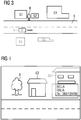
- FIG 3 shows a diagram to explain the functioning of the method according to the invention and the device according to the invention for providing information data on an object contained in a video image stream in a vehicle environment of a vehicle.
- a vehicle 1 is moving on a street S within an urban area, with various buildings G1 to G5 being located at the edge of the street.
- the buildings can be, for example, office buildings, private houses, public buildings or historical buildings.
- the buildings shown can also have other static objects on the edge of the street S, such as statues, monuments or trees. Further examples of static objects are bridges or sports stadiums and the like.
- the vehicle 1 drives past a building with a restaurant that the driver likes, he can tap on the displayed object in the displayed live video image stream or touch the screen at this point and immediately receives cloud information data on this selected object, ie to the selected restaurant.
- These information data in particular cloud information data, are preferably displayed on the screen in the immediate vicinity of the selected object or as an overlay over the displayed object.
- Figure 4 schematically shows a possible display on a display unit 5 of the camera surround view system 2.
- the driver of the vehicle 1 being interested in the object G3 .
- this building G3 there is an Italian restaurant, for example, in which the driver of the vehicle might want to reserve a table in the evening.
- the driver drives past a tree B, he taps on building G3 and selects it as the object.
- local cloud information data for the building G3 from a database 9 of a data network 8 are selected from the driving speed, the vehicle position and the direction of travel of the vehicle 1 and transmitted to the data processing unit 4 of the camera surround view system 2 via a wireless interface.
- the received cloud information data is inserted at the appropriate point in the live video image stream.
- the driver receives useful information data, for example the name of the Italian restaurant "Bella Italia” and further information, such as the desired telephone number to reserve seats "089/123456".
- the driver can then press a displayed link, for example the telephone number, and a telephone connection to the displayed restaurant is then automatically established so that the driver can conveniently make a reservation at the restaurant while driving in vehicle 1 over the phone.
- the driver can receive further specific information regarding the object of interest by actuating the displayed buttons. For example, the driver can press a restaurant with a menu symbol in the displayed cloud information data and a menu card of the restaurant is displayed.
- the displayed menu card can also be read out to the driver while driving by pressing a button, so that he is not distracted while driving.
- the driver can receive photos of the interior of the restaurant, ie a displayed picture gallery.
- the system draws the driver's attention to objects of interest at the edge of the road S, for example by means of an acoustic indication.
- an acoustic indication For example, at a certain point along the route, for example 100 m before driving past building G3, the driver of vehicle 1 can be made acoustically aware that he will be driving past an Italian restaurant within 100 m.
- the driver can select the announced object, for example, by touching the screen or the display unit 5.
- the driver can confirm the acoustic request with a command word so that cloud information data on the object of interest are automatically downloaded without the driver having to touch the display unit 5.
- the object of interest for example the restaurant
- the object of interest for example the one in Figure 4 represented restaurant
- this user interface has a microphone into which the driver gives acoustic commands to select the object.
- the display unit 5 can serve as a touchscreen as a user interface. If the user interface uses the display unit 5 as a touchscreen, the object is selected from the objects currently displayed in the live video image stream. It is also possible to select objects that are not currently displayed, but will be displayed in the future after driving a short distance. This example offers the advantage that the local cloud information data associated with the selected objects can be downloaded from a remote database and are already available when the object of interest is passed.
- the driver can select or filter different types of objects.
- the driver can select restaurants, gas stations or repair shops as the object type.
- the driver is only made aware of objects which correspond to the selected object type. For example, if a driver drives through a city unknown to him and is looking for a suitable restaurant, he can search specifically for objects of the object type restaurant. As soon as the vehicle approaches or passes the object of this object type, it can select this object and read the associated cloud information data in order to make its selection.
- the system according to the invention has an editor in which the driver can generate cloud information data on an object of interest, the generated cloud information data be uploaded by the driver from a database 9 of the data network 8. For example, after eating in the selected restaurant, a driver can submit his rating of the restaurant, which can be stored as additional cloud information data in the database 9 of the data network 8.
- the vehicle 1 can have a large number of display units 5, which are provided for different passengers of the vehicle 1.
- a tourist bus can be equipped with a plurality of display units 5 within a city tour, which show the vehicle passengers, ie the tourists, a live video image stream of the vehicle surroundings.
- a tourist is interested in a special building during the city tour that he sees through the window of the bus, he can at the same time select the building that is also shown on the display unit 5 by touching the screen and receives associated cloud information data on this building. In this way, a large number of tourists can simultaneously receive information about different objects of interest to them.
- the display unit 5 is a head-up display.
- the driver or a passenger of the vehicle can select an object visible through a window pane of the vehicle by touching the visible object on the window pane of the vehicle.
- the head-up display or the window pane serves as the user interface for selecting the object.
- the in Figure 1 The data network 8 shown is preferably a data network, in particular the Internet.
- the gateway 6 of the vehicle 1 communicates via a wireless interface, in particular a mobile radio interface, with an access point of an access network, which in turn is connected to the Internet.
- the system receives position data from further signal sources, for example via satellite or by means of odometry.
- a three-dimensional display image of the vehicle surroundings is displayed on the display unit 5.
- the objects are also displayed three-dimensionally and can be selected by the driver by touching the screen.
- the loaded local cloud information data for the selected objects are stored on a local data memory of the system so that they are already available locally in the local data memory of the vehicle the next time the object is selected. This minimizes the access times to the cloud information data of already selected objects.
- the location of the overlay data on the display or display unit 5 is preferably calculated by the data processing unit 4. The calculation is preferably carried out in real time.
Landscapes
- Engineering & Computer Science (AREA)
- Remote Sensing (AREA)
- Radar, Positioning & Navigation (AREA)
- Mechanical Engineering (AREA)
- Multimedia (AREA)
- Combustion & Propulsion (AREA)
- Transportation (AREA)
- Chemical & Material Sciences (AREA)
- Automation & Control Theory (AREA)
- Physics & Mathematics (AREA)
- General Physics & Mathematics (AREA)
- Theoretical Computer Science (AREA)
- Navigation (AREA)
- Traffic Control Systems (AREA)
- Instructional Devices (AREA)
Description
- Die Erfindung betrifft eine Vorrichtung und ein Verfahren zum Bereitstellen von Informationsdaten zu einem in einem Videobildstrom enthaltenen Objekt einer Fahrzeugumgebung eines Fahrzeuges, insbesondere eines Straßenfahrzeuges.
-
EP 0 867 690 A1 betrifft eine Vorrichtung und ein System zur Kennzeichnung von Bilddaten. Hierzu kann ein von einer Kamera bereitgestelltes Bild in mehrere Bereiche segmentiert werden. Basierend auf den Informationen über das segmentierte Bild können von einer externen Datenquelle zusätzliche Information empfangen werden und diese zusätzlichen Daten dem Kamerabild überlagert werden. - Kraftfahrzeuge, insbesondere Straßenfahrzeuge, werden zunehmend mit Fahrerassistenzsystemen ausgerüstet, die den Fahrer des Fahrzeuges beim Fahren des Fahrzeuges sowie bei Fahrmanövern unterstützen. Derartige Fahrerassistenzsysteme enthalten teilweise Kamera-Surround-View-Systeme, die über eine oder mehrere Fahrzeugkameras verfügen. Diese Fahrzeugkameras liefern Kamerabilder, welche dem Fahrer des Fahrzeuges auf einer Anzeigeeinheit des Fahrzeuges angezeigt werden. Diese Kamerabilder unterstützen beispielsweise den Fahrer beim Zurücksetzen des Fahrzeuges oder beim Einparken des Fahrzeuges in eine Parklücke.
- Weiterhin verfügen herkömmliche Fahrzeuge in vielen Fällen über ein Navigationssystem, welches Positionsdaten des Fahrzeuges liefert und dem Fahrer entlang einer Fahrroute zu einem Navigationsziel führt. Dabei kann der Fahrer auf einer angezeigten Straßenkarte eine Fahrtroute verfolgen und das Fahrzeug entsprechend den Anweisungen des Navigationssystems hin zu seinem Fahrziel lenken.
- Während der Fahrt zu seinem Fahrziel kommt es oft vor, dass dem Fahrer bestimmte, in der Fahrzeugumgebung befindliche Objekte, beispielsweise Gebäude oder auffällige Landmarken, auffallen, die für ihn aus verschiedensten Gründen von Interesse sind. Fährt beispielsweise ein Fahrer mit seinem Fahrzeug durch eine Stadt oder Stadtviertel oder durch einen Industriepark oder dergleichen, können ihm bestimmte Objekte, vor allem Gebäude, auffallen, zu denen er weitere Informationen wünscht. Beispielsweise möchte der Fahrer wissen, zu welchem Unternehmen ein Bürogebäude gehört. Weiterhin ist es möglich, dass ein Fahrer, der sich mit seinem Fahrzeug durch eine Stadt bewegt, historisch interessante Objekte erkennt, zu denen er gerne mehr erfahren möchte.
- Bei herkömmlichen Kamera-Surround-View-Systemen bzw. Fahrerassistenzsystemen besteht für den Fahrer nicht die Möglichkeit, direkt Informationen zu den für ihn interessanten Objekte innerhalb des Videobildstromes und/oder der angezeigten Kamerabilder zu erhalten.
- Es ist daher eine Aufgabe der vorliegenden Erfindung, ein Verfahren und eine Vorrichtung zu schaffen, welches dem Fahrer die Möglichkeit bietet, zu interessanten Objekten innerhalb der Fahrzeugumgebung auf einfache Weise zusätzliche Informationen zu erhalten.
- Diese Aufgabe wird erfindungsgemäß durch ein Kamera-Surround-View-System mit den in Patentanspruch 1 angegebenen Merkmalen gelöst.
- Weitere Ausführungsformen werden gemäß den beigefügten abhängigen Ansprüchen 2-7 bereitgestellt.
- Die Erfindung schafft ferner ein Verfahren zum Bereitstellen von Informationsdaten zu einem in einem Videobildstrom enthaltenen Objekt einer Fahrzeugumgebung eines Fahrzeuges mit den in Patentanspruch 8 angegebenen Merkmalen.
- Weitere Ausführungsformen werden gemäß den beigefügten abhängigen Ansprüchen 9-11 bereitgestellt.
- Im Weiteren werden mögliche Ausführungsformen des erfindungsgemäßen Verfahrens und der erfindungsgemäßen Vorrichtung zur Bereitstellung von Informationsdaten zu einem in einem Videobildstrom enthaltenen Objekt einer Fahrzeugumgebung eines Fahrzeuges unter Bezugnahme auf die beigefügten Figuren näher erläutert.
- Es zeigen:
- Figur 1
- ein Blockschaltbild zur Darstellung eines Ausführungsbeispiels des erfindungsgemäßen Kamera-Surround-View-Systems gemäß einem ersten Aspekt der Erfindung;
- Figur 2
- ein Ablaufdiagramm zur Darstellung eines Ausführungsbeispiels des erfindungsgemäßen Verfahrens zum Bereitstellen von Informationsdaten zu einem in einem Videobildstrom enthaltenen Objekt einer Fahrzeugumgebung;
- Figur 3
- eine schematische Darstellung eines Anwendungsfalls zur Erläuterung der Funktionsweise des erfindungsgemäßen Verfahrens und des erfindungsgemäßen Kamera-Surround-View-Systems;
- Figur 4
- eine beispielhafte Anzeige auf einer Anzeigeeinheit bei dem in
Figur 3 dargestellten Anwendungsfall zur Erläuterung der Funktionsweise des erfindungsgemäßen Verfahrens und der erfindungsgemäßen Vorrichtung zur Bereitstellung von Informationsdaten. - Wie man aus
Figur 1 erkennen kann, verfügt bei dem dargestellten Anwendungsbeispiel ein Fahrzeug 1, insbesondere ein Straßenfahrzeug, beispielsweise ein Lkw oder Pkw, über ein Kamera-Surround-View-System 2. Das Kamera-Surround-View-System 2 enthält mindestens eine Fahrzeugkamera 3, die Kamerabilder der Fahrzeugumgebung liefert, welche durch eine Datenverarbeitungseinheit 4 des Kamera-Surround-View-Systems 2 zur Erzeugung eines Live-Videobildstromes verarbeitet werden, der auf einer Anzeigeeinheit 5 angezeigt wird. Der Live-Videobildstrom wird beispielsweise auf einem Display innerhalb des Passagierraumes dem Fahrer oder einem Passagier des Fahrzeuges 1 angezeigt. Die Datenverarbeitungseinheit 4 des Kamera-Surround-View-Systems 2 enthält bei einer möglichen Ausführungsform einen oder mehrere Mikroprozessoren zur Verarbeitung der erhaltenen Kamerabilder zu einem Live-Videobildstrom der Fahrzeugumgebung. Die Anzahl der Fahrzeugkameras 3 kann je nach Typ und Größe des Fahrzeuges 1 variieren. Beispielsweise kann ein größeres Fahrzeug 1, beispielsweise ein Lkw oder ein Kreuzfahrtschiff, eine Vielzahl von Fahrzeugkameras 3 besitzen, die durch die Datenverarbeitungseinheit 4 zu einem komplexen Live-Videobildstrom verarbeitet werden. - Die Datenverarbeitungseinheit 4 ist über Datenleitungen bzw. einem Datenbus mit einem Gateway 6 des Fahrzeuges verbunden. Bei dem Datenbus handelt es sich beispielsweise um einen Ethernet-Datenbus. Das Gateway 6 ist bei dem dargestellten Ausführungsbeispiel über einen weiteren Fahrzeugbus, beispielsweise einem CAN-Bus, mit einer GPS-Einheit 7 des Fahrzeuges verbunden, welche GPS-Koordinaten zu der aktuellen Position des Fahrzeuges 1 liefert. Die GPS-Einheit 7 kann Teil des Navigationssystems des Fahrzeuges 1 sein. Das Gateway 6 ist über eine drahtlose Schnittstelle, beispielsweise eine Mobilfunkschnittstelle, mit einem Datennetzwerk 8 verbunden. Bei der Mobilfunkschnittstelle kann es sich beispielsweise um eine UMTS-Schnittstelle handeln. Das Datennetzwerk 8 verfügt über eine oder mehrere Datenbanken 9, in der Cloud-Informationsdaten gespeichert sind. Das in
Figur 1 dargestellte System kann über weitere Komponenten verfügen, beispielsweise über Datenspeicher bzw. Datenzwischenspeicher zum Speichern von temporär heruntergeladenen Cloud-Informationsdaten. Das inFigur 1 dargestellte Kamera-Surround-View-System 2 erhält lokale Cloud-Informationsdaten hinsichtlich eines in dem Live-Videobildstrom dargestellten Objektes zu dem Datennetzwerk 8 über die drahtlose Schnittstelle und das Gateway 6 und zeigt die erhaltenen lokalen Cloud-Informationsdaten als Overlay in dem auf der Anzeigeeinheit 5 angezeigten Live-Videobildstrom an. Dabei werden die lokalen Cloud-Informationsdaten von der Datenbank 9 des Datennetzwerkes 8 vorzugsweise in Abhängigkeit von einer aktuellen Position, der Fahrtrichtung und/oder der Fahrgeschwindigkeit des Fahrzeuges 1 und dem ausgewählten Objekt heruntergeladen. Die Informationen hinsichtlich der Fahrtrichtung und der Fahrgeschwindigkeit des Fahrzeuges 1 werden vorzugsweise durch weitere, nicht inFigur 1 dargestellte Sensoreinheiten des Fahrzeuges 1 geliefert. - Bei dem erfindungsgemäßen Kamera-Surround-View-System 2 wird das ausgewählte interessierende Objekt, beispielsweise ein Gebäude am Rand der Straße, von einem Fahrer des Fahrzeuges 1 oder einem in dem Fahrzeug befindlichen Passagier mittels eines Nutzerinterfaces selektiert. Bei einer möglichen bevorzugten Ausführungsform bildet das Nutzerinterface die Anzeigeeinheit 5 als Touchscreen. Bei dieser Ausführungsform wird das interessierende Objekt von dem Fahrer oder Passagier ausgewählt, indem der Fahrer oder Passagier das auf der Anzeigeeinheit 5 angezeigte Objekt berührt.
- Bei dem erfindungsgemäßen Kamera-Surround-View-System 2 berechnet die Datenverarbeitungseinheit 4 des Surround-View-Systems 2 einen Pointer von Kamerakoordinaten des ausgewählten Objektes, welches innerhalb des Live-Videobildstromes auf der Anzeigeeinheit 5 angezeigt wird, zu GPS-Koordinaten und generiert anschließend eine Anforderung bzw. einen Request, welcher über die drahtlose Verbindung ausgesendet wird, um die zu dem ausgewählten Objekt zugehörigen Cloud-Informationsdaten von der Datenbank 9 des Datennetzwerkes 8 zu erhalten. Bei einer möglichen Ausführungsform erhält die Datenverarbeitungseinheit 4 des Surround-View-Systems 2 über die drahtlose Verbindung als Reaktion auf die Anfrage eine Liste von GPS-Koordinaten sowie zugehörige lokale Cloud-Informationsdaten von der Datenbank 9 des Datennetzwerkes 8 und berechnet anschließend einen Pointer von den GPS-Koordinaten zu den Kamerakoordinaten, an deren Stelle die lokalen heruntergeladenen Cloud-Informationsdaten in den angezeigten Live-Videobildstrom durch die Datenverarbeitungseinheit 4 platziert werden. Verschiedene Varianten des erfindungsgemäßen Kamera-Surround-View-Systems 2 sind möglich. Bei der in
Figur 1 dargestellten Ausführungsform erfolgt das Einfügen der lokalen Cloud-Informationsdaten in den Live-Videobildstrom durch die Datenverarbeitungseinheit 4 des Kamera-Surround-View-Systems 2. Bei einer alternativen Ausführungsform erfolgt das Einfügen der Cloud-Informationsdaten in den Videobildstrom durch eine weitere separate Datenverarbeitungseinheit des Surround-View-Systems 2. Bei einer weiteren Ausführungsform kann die Datenverarbeitung auch remote durch eine Berechnungseinheit bzw. einen Server des Datennetzwerkes 8 erfolgen, wobei dieser einen Live-Videobildstrom erzeugt, in dem bereits Cloud-Informationsdaten zu ausgewählten Objekten eingefügt sind und dieser aufbereitete Videobildstrom über eine drahtlose Schnittstelle zu einer Empfangseinheit des Kamera-Surround-View-Systems 2 zurückgesendet wird. - Bei möglichen Anwendungsfällen erfolgt das Einfügen der Cloud-Informationsdaten in den Live-Videobildstrom vorzugsweise in Echtzeit mit möglichst geringer Zeitverzögerung. Bei diesen Anwendungsfällen erfolgt die Datenverarbeitung vorzugsweise durch die Datenverarbeitungseinheit 4 innerhalb des Kamera-Surround-View-Systems 2. Bei anderen Anwendungsfällen können die lokalen Cloud-Informationsdaten auch mit einer leichten Zeitverzögerung in den Live-Videobildstrom eingefügt werden, so dass in diesen Anwendungsfällen auch die Datenaufbereitung durch eine Datenverarbeitungseinheit außerhalb des Fahrzeuges 1 möglich ist.
-
Figur 2 zeigt ein Ablaufdiagramm zur Darstellung eines Ausführungsbeispiels des erfindungsgemäßen Verfahrens zum Bereitstellen von Informationsdaten, insbesondere Cloud-Informationsdaten, zu einem in einem Videobildstrom enthaltenen Objekt einer Fahrzeugumgebung eines Fahrzeuges. - In einem ersten Schritt S1 werden zunächst Kamerabilder von mindestens einer Fahrzeugkamera des Fahrzeuges 1 erzeugt, welche eine Fahrzeugumgebung des Fahrzeuges darstellen. Bei einer möglichen Ausführungsform verfügt das Fahrzeug über eine Vielzahl von Fahrzeugkameras, welche die gesamte Fahrzeugumgebung, d.h. 360°, um das Fahrzeug herum darstellen.
- In einem weiteren Schritt S2 werden die erzeugten Kamerabilder zur Generierung eines Life-Videobildstromes der Fahrzeugumgebung verarbeitet. Diese Datenverarbeitung kann beispielsweise durch die in
Figur 1 dargestellte Datenverarbeitungseinheit 4 eines Kamera-Surround-View-Systems 2 durchgeführt werden. - In einem weiteren Schritt S3 wird der generierte Live-Videobildstrom auf einer Anzeigeeinheit 5 des Fahrzeuges 1 angezeigt, wobei Cloud-Informationsdaten hinsichtlich eines ausgewählten Objektes innerhalb des Live-Videobildstromes als Overlay in dem Live-Videobildstrom angezeigt werden. Das ausgewählte interessierende Objekt wird von einem Fahrer des Fahrzeuges 1 oder einem in dem Fahrzeug 1 befindlichen Passagier mittels eines Nutzerinterfaces selektiert. Vorzugsweise wird das interessierende Objekt von dem Fahrer oder Passagier ausgewählt, indem der Fahrer oder Passagier das auf der Anzeigeeinheit 5 des Kamera-Surround-View-Systems 2 angezeigte Objekt, beispielsweise ein dargestelltes Gebäude, berührt. Die im Schritt S3 angezeigten Cloud-Informationsdaten werden vorzugsweise von einer Datenbank eines Datennetzwerkes heruntergeladen, wobei lokale Cloud-Informationsdaten, welche zu dem selektierten Objekt gehören, von dem Datennetzwerk in Abhängigkeit von einer aktuellen Position, Fahrtrichtung und/oder Fahrgeschwindigkeit des Fahrzeuges 1 in Abhängigkeit von dem ausgewählten Objekt aus einer Datenbank heruntergeladen werden. Die aktuelle Position, Fahrtrichtung und/oder Fahrgeschwindigkeit werden durch eine GPS-Einheit oder weitere Sensoreinheiten des Fahrzeuges 1 der jeweiligen Datenverarbeitungseinheit zur Verfügung gestellt. Erfindungsgemäß wird ein Pointer von Kamerakoordinaten des ausgewählten Objektes, welches sich innerhalb des Live-Videobildstromes befindet, zu GPS-Koordinaten berechnet. Anschließend wird eine Anforderung über eine drahtlose Verbindung ausgesendet, um die zu dem ausgewählten Objekt zugehörigen Cloud-Informationsdaten von der Datenbank des Datennetzwerkes erhalten. Bei einer möglichen Ausführungsform wird über die drahtlose Verbindung eine Liste von GPS-Koordinaten und zugehörigen lokalen Cloud-Informationsdaten von der Datenbank des Datennetzwerkes empfangen und anschließend ein Pointer von den GPS-Koordinaten zu den Kamerakoordinaten, an deren Stelle die lokalen Cloud-Informationsdaten in den angezeigten Live-Videobildstrom platziert werden, durch die Datenverarbeitungseinheit berechnet.
-
Figur 3 zeigt ein Diagramm zur Erläuterung der Funktionsweise des erfindungsgemäßen Verfahrens und der erfindungsgemäßen Vorrichtung zum Bereitstellen von Informationsdaten zu einem in einem Videobildstrom enthaltenen Objekt in einer Fahrzeugumgebung eines Fahrzeuges. Bei dem inFigur 3 dargestellten Beispiel bewegt sich ein Fahrzeug 1 auf einer Straße S innerhalb eines Stadtgebietes, wobei sich am Rand der Straße verschiedene Gebäude G1 bis G5 befinden. Bei den Gebäuden kann es sich beispielsweise um Bürogebäude, Privathäuser, öffentliche Gebäude oder historische Gebäude handeln. Neben den inFigur 3 dargestellten Gebäuden können auch weitere statische Objekte am Rand der Straße S stehen, wie beispielsweise Statuen, Monumente oder Bäume. Weitere Beispiele für statische Objekte sind Brücken oder Sportstadien und dergleichen. Fährt beispielsweise das Fahrzeug 1 an einem Gebäude mit einem Restaurant vorbei, welches dem Fahrer gefällt, kann er in dem angezeigten Live-Videobildstrom auf das angezeigte Objekt tippen bzw. den Bildschirm an dieser Stelle berühren und erhält unmittelbar Cloud-Informationsdaten zu diesem ausgewählten Objekt, d.h. zu dem ausgewählten Restaurant. Diese Informationsdaten, insbesondere Cloud-Informationsdaten, werden vorzugsweise auf dem Bildschirm in unmittelbarer Nähe zu dem ausgewählten Objekt bzw. als Overlay über dem angezeigten Objekt angezeigt. -
Figur 4 zeigt schematisch eine mögliche Anzeige auf einer Anzeigeeinheit 5 des Kamera-Surround-View-Systems 2. In dem einfachen Beispiel befinden sich zwei Objekte G2, G3 auf der linken Straßenseite der Straße S, wobei sich der Fahrer des Fahrzeuges 1 für das Objekt G3 interessiert. In diesem Gebäude G3 befindet sich beispielsweise ein italienisches Restaurant, in dem der Fahrer des Fahrzeuges möglicherweise abends einen Tisch reservieren möchte. Sobald der Fahrer an einem Baum B vorbeifährt, tippt er auf das Gebäude G3 und wählt dieses als Objekt aus. Anschließend werden aus der Fahrgeschwindigkeit, der Fahrzeugposition und der Fahrtrichtung des Fahrzeuges 1 lokale Cloud-Informationsdaten zu dem Gebäude G3 aus einer Datenbank 9 eines Datennetzwerkes 8 selektiert und über eine drahtlose Schnittstelle an die Datenverarbeitungseinheit 4 des Kamera-Surround-View-Systems 2 übertragen. Die empfangenen Cloud-Informationsdaten werden an der passenden Stelle in den Live-Videobildstrom eingefügt. Der Fahrer erhält nützliche Informationsdaten, beispielsweise den Namen des italienischen Restaurants "Bella Italia" und weitere Informationen, wie beispielsweise die gewünschte Telefonnummer zur Platzreservierung "089/123456". Bei einer weiteren möglichen Ausführungsform kann der Fahrer anschließend auf ein angezeigtes Link, beispielsweise die Telefonnummer, drücken und es wird daraufhin automatisch eine Telefonverbindung zu dem angezeigten Restaurant hergestellt, sodass der Fahrer während der Fahrt in dem Fahrzeug 1 in bequemer Weise eine Reservierung bei dem Restaurant telefonisch vornehmen kann. Darüber hinaus ist es möglich, dass der Fahrer durch Betätigen von angezeigten Schaltflächen weitere spezielle Informationen hinsichtlich des interessierenden Objektes erhält. Beispielsweise kann der Fahrer bei den dargestellten Cloud-Informationsdaten auf ein Restaurant mit Menüsymbol drücken und erhält eine Menükarte des Restaurants angezeigt. Bei einer weiteren möglichen Ausführungsform kann durch Betätigen einer Schaltfläche die angezeigte Menükarte auch dem Fahrer während der Fahrt vorgelesen werden, sodass er während der Fahrt nicht abgelenkt wird. Darüber hinaus kann der Fahrer durch Betätigen einer weiteren Schaltfläche Fotos vom Inneren des Restaurants erhalten, d.h. eine angezeigte Bildergalerie. - Weitere Ausführungsvarianten sind möglich. Beispielsweise wird der Fahrer bei einer möglichen Ausführungsform durch das System auf interessante Objekte am Rand der Straße S aufmerksam gemacht, beispielsweise durch einen akustischen Hinweis. Beispielsweise kann der Fahrer des Fahrzeuges 1 an einer gewissen Stelle entlang der Fahrtroute, beispielsweise 100 m, bevor er an dem Gebäude G3 vorbeifährt, akustisch darauf aufmerksam gemacht werden, dass er in 100 m an einem italienischen Restaurant vorbeifahren wird. Der Fahrer kann beispielsweise durch Berühren des Bildschirms bzw. der Anzeigeeinheit 5 das angekündigte Objekt auswählen. Bei einer weiteren möglichen Ausführungsvariante kann der Fahrer die akustische Anfrage mit einem Befehlswort bestätigen, sodass Cloud-Informationsdaten zu dem interessierenden Objekt automatisch heruntergeladen werden, ohne dass der Fahrer die Anzeigeeinheit 5 berühren muss. Bei dieser Ausführungsvariante ist nicht notwendig, dass das interessierende Objekt, beispielsweise das Restaurant, zum Zeitpunkt der Selektion bereits dem Fahrer auf der Anzeigeeinheit 5 angezeigt wird. Mit dem erfindungsgemäßen System wird das interessierende Objekt, beispielsweise das in
Figur 4 dargestellte Restaurant, von einem Fahrer des Fahrzeuges 1 oder einem in dem Fahrzeug befindlichen Passagier mittels eines Nutzerinterfaces selektiert. Bei einer möglichen Ausführungsform weist dieses Nutzerinterface ein Mikrofon auf, in welches der Fahrer akustische Befehle zum Auswählen des Objektes eingibt. Alternativ kann als Nutzerinterface die Anzeigeeinheit 5 als Touchscreen dienen. Benutzt das Nutzerinterface die Anzeigeeinheit 5 als Touchscreen, erfolgt die Auswahl des Objektes aus den in dem Live-Videobildstrom aktuell angezeigten Objekten. Weiterhin ist es möglich, dass auch Objekte ausgewählt werden, die aktuell noch nicht angezeigt werden, jedoch zukünftig nach Fahren einer kurzen Strecke angezeigt werden. Dieses Beispiel bietet den Vorteil, dass die zu den ausgewählten Objekten zugehörigen lokalen Cloud-Informationsdaten von einer entfernten Datenbank heruntergeladen werden können und zum Zeitpunkt des Passierens des interessierenden Objektes bereits zur Verfügung stehen. - Bei einer möglichen weiteren Ausführungsvariante des erfindungsgemäßen Systems kann der Fahrer verschiedene Typen von Objekten auswählen bzw. filtern. Beispielsweise kann der Fahrer Restaurants, Tankstellen oder Reparaturwerkstätten als Objekttyp auswählen. In diesem Falle wird der Fahrer bei einer möglichen Ausführungsform lediglich auf Objekte aufmerksam gemacht, welche dem ausgewählten Objekttyp entsprechen. Fährt beispielsweise ein Fahrer durch eine ihm unbekannte Stadt und sucht er ein für ihn passendes Restaurant, kann er gezielt nach Objekten des Objekttyps Restaurant suchen. Sobald sich das Fahrzeug dem Objekt dieses Objekttyps nähert oder passiert, kann er dieses Objekt auswählen und die zugehörigen Cloud-Informationsdaten lesen, um seine Auswahl zu treffen.
- Bei einer weiteren möglichen Ausführungsvariante verfügt das erfindungsgemäße System über einen Editor, bei dem der Fahrer Cloud-Informationsdaten zu einem interessierenden Objekt erzeugen kann, wobei die erzeugten Cloud-Informationsdaten durch den Fahrer von einer Datenbank 9 des Datennetzwerkes 8 hochgeladen werden. Beispielsweise kann ein Fahrer nach dem Essen in dem ausgewählten Restaurant seine Bewertung des Restaurants abgeben, die als zusätzliche Cloud-Informationsdaten in der Datenbank 9 des Datennetzwerkes 8 abgelegt werden können.
- Das erfindungsgemäße System ist vielfältig einsetzbar. Beispielsweise kann das Fahrzeug 1 über eine Vielzahl von Anzeigeeinheiten 5 verfügen, die für verschiedene Passagiere des Fahrzeuges 1 vorgesehen sind. Beispielsweise kann ein Touristenbus innerhalb einer Stadtrundfahrt mit einer Vielzahl von Anzeigeeinheiten 5 ausgestattet sein, die den Fahrzeugpassagieren, d.h. den Touristen, einen Live-Videobildstrom der Fahrzeugumgebung zeigen. Interessiert sich beispielsweise ein Tourist während der Stadtrundfahrt für ein besonderes Gebäude, das er durch das Fenster das Fahrbusses sieht, kann er gleichzeitig das auf der Anzeigeeinheit 5 ebenfalls dargestellte Gebäude durch Berühren des Bildschirms auswählen und erhält zugehörige Cloud-Informationsdaten zu diesem Gebäude. Auf diese Weise können eine Vielzahl von Touristen gleichzeitig über unterschiedliche sie individuell interessierende Objekte Informationen erhalten. Bei einer weiteren möglichen Ausführungsvariante handelt es sich bei der Anzeigeeinheit 5 um ein Headup-Display. Bei dieser Ausführungsvariante kann der Fahrer oder ein Passagier des Fahrzeuges ein durch eine Fensterscheibe des Fahrzeuges sichtbares Objekt auswählen, indem er das sichtbare Objekt auf der Fensterscheibe des Fahrzeuges berührt. Bei dieser Ausführungsvariante dient somit das Headup-Display bzw. die Fensterscheibe das Nutzerinterface zum Auswählen des Objektes. Bei dem in
Figur 1 dargestellten Datennetzwerk 8 handelt es sich vorzugsweise um einen Datennetzwerkverbund, insbesondere das Internet. Bei einer möglichen Ausführungsform kommuniziert das Gateway 6 des Fahrzeuges 1 über eine drahtlose Schnittstelle, insbesondere eine Mobilfunkschnittstelle, mit einem Zugangspunkt eines Zugangsnetzwerkes, welches seinerseits mit dem Internet verbunden ist. Bei einer weiteren möglichen Ausführungsvariante erhält das System Positionsdaten von weiteren Signalquellen, beispielsweise via Satellit oder mittels Odometrie. Bei einer möglichen Ausführungsform wird auf der Anzeigeeinheit 5 ein dreidimensionales Anzeigenbild der Fahrzeugumgebung angezeigt. Bei dieser Ausführungsform werden auch die Objekte dreidimensional angezeigt und können durch den Fahrer durch Berühren des Bildschirms ausgewählt werden. - Bei einer weiteren möglichen Ausführungsvariante werden die geladenen lokalen Cloud-Informationsdaten zu den ausgewählten Objekten auf einem lokalen Datenspeicher des Systems gespeichert, sodass sie beim nächsten Auswählen des Objektes bereits lokal in dem lokalen Datenspeicher des Fahrzeuges zur Verfügung stehen. Hierdurch werden die Zugriffszeiten auf die Cloud-Informationsdaten bereits ausgewählter Objekte minimiert.
- Auf Basis der gelieferten aus der Cloud stammenden GPS-Daten, der Position des Fahrzeuges und dem Blickwinkel der virtuellen Kamera wird vorzugsweise durch die Datenverarbeitungseinheit 4 der Darstellungsort der Overlay-Daten auf dem Display bzw. der Anzeigeeinheit 5 berechnet. Die Berechnung erfolgt dabei vorzugsweise in Echtzeit.
Claims (11)
- Kamera-Surround-View-System (2) für ein Fahrzeug (1) mit mindestens einer Fahrzeugkamera (3), die Kamerabilder liefert, welche durch eine Datenverarbeitungseinheit (4) zur Erzeugung eines Live-Videobildstromes verarbeitet werden, der auf einer Anzeigeeinheit (5) angezeigt wird, wobei das Kamera-Surround-View-System (2) lokale Cloud-Informationsdaten hinsichtlich eines in dem Live-Videobildstrom dargestellten Objektes von einem Datennetzwerk (8) lädt und die erhaltenen lokalen Cloud-Informationsdaten als Overlay in dem angezeigten Live-Videobildstrom anzeigt,
wobei ein ausgewähltes interessierendes Objekt von einem Fahrer des Fahrzeuges (1) oder einem in dem Fahrzeug (1) befindlichen Passagier mittels eines Nutzerinterfaces selektiert wird,
wobei das Kamera-Surround-View-System (2) einen Pointer von Kamerakoordinaten des ausgewählten Objektes, welches sich innerhalb des Live-Videobildstromes befindet, zu GPS-Koordinaten des ausgewählten Objektes berechnet und eine Anforderung über die drahtlose Verbindung sendet, um die zu dem Objekt zugehörigen Cloud-Informationsdaten von einer Datenbank (9) des Datennetzwerkes (8) zu erhalten, und
wobei die lokalen Cloud-Informationen über eine drahtlose Schnittstelle und ein Gateway (6) heruntergeladen werden, wobei das Gateway (6) über einen Datenbus mit der Datenverarbeitungseinheit (4) und mit einem weiteren Fahrzeugbus mit einer GPS-Einheit (7) des Fahrzeugs verbunden ist, und wobei die heruntergeladenen Cloud-Informationen in einem Datenspeicher temporär zwischengespeichert werden. - Kamera-Surround-View-System nach Anspruch 1,
wobei die lokalen Cloud-Informationsdaten von dem Datennetzwerk in Abhängigkeit von einer aktuellen Position, Fahrtrichtung und/oder Fahrgeschwindigkeit des Fahrzeuges (1) und dem ausgewählten Objekt herunterladbar sind. - Kamera-Surround-View-System nach Anspruch 1 oder 2,
wobei das ausgewählte Objekt von dem Fahrer oder Passagier ausgewählt wird, indem der Fahrer oder Passagier das auf der Anzeigeeinheit (5) angezeigte Objekt berührt. - Kamera-Surround-View-System nach einem der vorangehenden Ansprüche 1 bis 3,
wobei das Kamera-Surround-View-System (2) mit dem Gateway (6) verbunden ist, das eine drahtlose Verbindung zu dem Datennetzwerk (8) bereitstellt. - Kamera-Surround-View-System nach einem der vorangehenden Ansprüche 1 bis 4,
wobei die aktuelle Position, Fahrtrichtung und/oder Fahrgeschwindigkeit durch die GPS-Einheit (7) des Fahrzeuges (1) bereitgestellt werden. - Kamera-Surround-View-System nach einem der Ansprüche 1 bis 5,
wobei das Kamera-Surround-View-System (2) über die drahtlose Verbindung eine Liste von GPS-Koordinaten und zugehörige lokale Cloud-Informationsdaten von der Datenbank (9) des Datennetzwerkes (8) erhält und einen Pointer von den GPS-Koordinaten zu den Kamerakoordinaten, an deren Stelle die lokalen Cloud-Informationsdaten in den angezeigten Live-Videobildstrom platziert werden, berechnet. - Fahrerassistenzsystem mit einem Kamera-Surround-View-System (2) nach einem der vorangehenden Ansprüche 1 bis 6.
- Verfahren zum Bereitstellen von Informationsdaten zu einem in einem Videobildstrom enthaltenen Objekt einer Fahrzeugumgebung eines Fahrzeuges (1) mit den Schritten:(a) Erzeugen (S1) von Kamerabildern der Fahrzeugumgebung durch mindestens eine Fahrzeugkamera des Fahrzeuges;(b) Verarbeiten (S2) der erzeugten Kamerabilder zur Generierung eines Live-Videobildstromes der Fahrzeugumgebung;(c) Anzeigen (S3) des generierten Live-Videobildstromes auf einer Anzeigeeinheit des Fahrzeuges,wobei ein ausgewähltes interessierendes Objekt von einem Fahrer des Fahrzeuges (1) oder einem in dem Fahrzeug (1) befindlichen Passagier mittels eines Nutzerinterfaces selektiert wird,
wobei Cloud-Informationsdaten hinsichtlich des ausgewählten Objektes innerhalb des Live-Videobildstromes als Overlay in dem Live-Videobildstrom angezeigt werden, wobei ein Pointer von Kamerakoordinaten des ausgewählten Objektes, welches sich innerhalb des Live-Videobildstromes befindet, zu GPS-Koordinaten des ausgewählten Objektes berechnet wird und eine Anforderung über eine drahtlose Verbindung ausgesendet wird, um die zu dem Objekt zugehörigen Cloud-Informationsdaten von einer Datenbank des Datennetzwerkes zu erhalten, und
wobei die lokalen Cloud-Informationen über eine drahtlose Schnittstelle und ein Gateway (6)heruntergeladen werden, wobei das Gateway (6) über einen Datenbus mit der Datenverarbeitungseinheit (4) und mit einem weiteren Fahrzeugbus mit einer GPS-Einheit (7) des Fahrzeugs verbunden ist, und wobei die heruntergeladenen Cloud-Informationen in einem Datenspeicher temporär zwischengespeichert werden. - Verfahren nach Anspruch 8,
wobei lokale Cloud-Informationsdaten von einem Datennetzwerk in Abhängigkeit von einer aktuellen Position, Fahrtrichtung und/oder Fahrgeschwindigkeit des Fahrzeuges und dem ausgewählten Objekt heruntergeladen werden. - Verfahren nach Anspruch 8 oder 9,
wobei das ausgewählte Objekt von dem Fahrer oder Passagier ausgewählt wird, indem der Fahrer oder Passagier das auf der Anzeige angezeigte Objekt berührt. - Verfahren nach einem der Ansprüche 8 bis 10,
wobei über die drahtlose Verbindung eine Liste von GPS-Koordinaten und zugehörige lokale Cloud-Informationsdaten von der Datenbank des Datennetzwerkes übertragen werden und ein Pointer von den GPS-Koordinaten zu den Kamerakoordinaten, an deren Stelle die lokalen Cloud-Informationsdaten in den angezeigten Live-Videobildstrom platziert werden, berechnet wird.
Applications Claiming Priority (2)
| Application Number | Priority Date | Filing Date | Title |
|---|---|---|---|
| DE102014208663.9A DE102014208663A1 (de) | 2014-05-08 | 2014-05-08 | Vorrichtung und verfahren zur bereitstellung von informationsdaten zu einem in einem videobildstrom enthaltenen objekt einer fahrzeugumgebung |
| PCT/DE2015/200279 WO2015169310A1 (de) | 2014-05-08 | 2015-04-24 | Vorrichtung und verfahren zur bereitstellung von informationsdaten zu einem in einem videobildstrom enthaltenen objekt einer fahrzeugumgebung |
Publications (3)
| Publication Number | Publication Date |
|---|---|
| EP3140617A1 EP3140617A1 (de) | 2017-03-15 |
| EP3140617B1 true EP3140617B1 (de) | 2020-12-16 |
| EP3140617B8 EP3140617B8 (de) | 2021-02-24 |
Family
ID=53054821
Family Applications (1)
| Application Number | Title | Priority Date | Filing Date |
|---|---|---|---|
| EP15720904.0A Active EP3140617B8 (de) | 2014-05-08 | 2015-04-24 | Vorrichtung und verfahren zur bereitstellung von informationsdaten zu einem in einem videobildstrom enthaltenen objekt einer fahrzeugumgebung |
Country Status (5)
| Country | Link |
|---|---|
| US (1) | US10227042B2 (de) |
| EP (1) | EP3140617B8 (de) |
| JP (1) | JP6744221B2 (de) |
| DE (2) | DE102014208663A1 (de) |
| WO (1) | WO2015169310A1 (de) |
Families Citing this family (24)
| Publication number | Priority date | Publication date | Assignee | Title |
|---|---|---|---|---|
| US11006095B2 (en) | 2015-07-15 | 2021-05-11 | Fyusion, Inc. | Drone based capture of a multi-view interactive digital media |
| US11095869B2 (en) | 2015-09-22 | 2021-08-17 | Fyusion, Inc. | System and method for generating combined embedded multi-view interactive digital media representations |
| US12495134B2 (en) | 2015-07-15 | 2025-12-09 | Fyusion, Inc. | Drone based capture of multi-view interactive digital media |
| US12261990B2 (en) | 2015-07-15 | 2025-03-25 | Fyusion, Inc. | System and method for generating combined embedded multi-view interactive digital media representations |
| US10222932B2 (en) | 2015-07-15 | 2019-03-05 | Fyusion, Inc. | Virtual reality environment based manipulation of multilayered multi-view interactive digital media representations |
| US10242474B2 (en) | 2015-07-15 | 2019-03-26 | Fyusion, Inc. | Artificially rendering images using viewpoint interpolation and extrapolation |
| US10147211B2 (en) | 2015-07-15 | 2018-12-04 | Fyusion, Inc. | Artificially rendering images using viewpoint interpolation and extrapolation |
| US11783864B2 (en) | 2015-09-22 | 2023-10-10 | Fyusion, Inc. | Integration of audio into a multi-view interactive digital media representation |
| US10094093B2 (en) * | 2015-11-16 | 2018-10-09 | Caterpillar Inc. | Machine onboard activity and behavior classification |
| DE102015015510A1 (de) * | 2015-11-30 | 2017-06-01 | Audi Ag | Verfahren zum Erkennen eines Objekts anhand einer Lage des Objekts in einem Bild, Vorrichtung und Kraftfahrzeug |
| DE102015015437A1 (de) | 2015-12-02 | 2017-06-08 | Conti Temic Microelectronic Gmbh | Steuergerät und Verfahren für ein Fahrerassistenzsystem eines Fahrzeugs |
| US11202017B2 (en) | 2016-10-06 | 2021-12-14 | Fyusion, Inc. | Live style transfer on a mobile device |
| US10437879B2 (en) | 2017-01-18 | 2019-10-08 | Fyusion, Inc. | Visual search using multi-view interactive digital media representations |
| US20180227482A1 (en) | 2017-02-07 | 2018-08-09 | Fyusion, Inc. | Scene-aware selection of filters and effects for visual digital media content |
| US10313651B2 (en) | 2017-05-22 | 2019-06-04 | Fyusion, Inc. | Snapshots at predefined intervals or angles |
| US10339392B2 (en) | 2017-06-15 | 2019-07-02 | Blackberry Limited | Method and system for rear status detection |
| US11069147B2 (en) | 2017-06-26 | 2021-07-20 | Fyusion, Inc. | Modification of multi-view interactive digital media representation |
| US10592747B2 (en) | 2018-04-26 | 2020-03-17 | Fyusion, Inc. | Method and apparatus for 3-D auto tagging |
| US11589082B2 (en) * | 2018-11-27 | 2023-02-21 | Toyota Motor North America, Inc. | Live view collection and transmission system |
| US11012637B2 (en) | 2019-02-01 | 2021-05-18 | Ford Global Technologies, Llc | Systems and methods for live video freeze detection |
| WO2020263816A1 (en) | 2019-06-24 | 2020-12-30 | Dd Dannar Llc | Battery communication and control systems and methods |
| US11893890B2 (en) | 2019-09-16 | 2024-02-06 | Nissan Motor Co., Ltd. | Information processing device and method for vehicle |
| US12524960B2 (en) | 2023-07-14 | 2026-01-13 | Nvidia Corporation | Spatial masking for stitched images and surround view visualizations |
| DE102023208082A1 (de) | 2023-08-23 | 2025-02-27 | Continental Autonomous Mobility Germany GmbH | Verfahren zum Erzeugen einer Bilddarstellung, Steuereinrichtung, Fahrerassistenzsystem und Fahrzeug |
Family Cites Families (19)
| Publication number | Priority date | Publication date | Assignee | Title |
|---|---|---|---|---|
| JP3053169B2 (ja) * | 1997-08-07 | 2000-06-19 | 日本電信電話株式会社 | 景観ラベル利用型通信装置およびシステム |
| US6222583B1 (en) * | 1997-03-27 | 2001-04-24 | Nippon Telegraph And Telephone Corporation | Device and system for labeling sight images |
| JP3601451B2 (ja) * | 2001-01-24 | 2004-12-15 | 株式会社デンソー | 自動車位置情報による自動車の制御方法 |
| JP3931336B2 (ja) | 2003-09-26 | 2007-06-13 | マツダ株式会社 | 車両用情報提供装置 |
| KR20050081492A (ko) | 2004-02-13 | 2005-08-19 | 디브이에스 코리아 주식회사 | 전방 실제 영상을 사용한 자동차 항법 장치 및 그 제어 방법 |
| DE102006030278A1 (de) * | 2006-06-30 | 2008-01-03 | Siemens Ag | Generierung einer Fahrsituation |
| DE102008051756A1 (de) * | 2007-11-12 | 2009-05-14 | Volkswagen Ag | Multimodale Benutzerschnittstelle eines Fahrerassistenzsystems zur Eingabe und Präsentation von Informationen |
| US8315796B2 (en) * | 2007-12-28 | 2012-11-20 | Mitsubishi Electric Corporation | Navigation device |
| JP2009229180A (ja) * | 2008-03-21 | 2009-10-08 | Mitsubishi Electric Corp | ナビゲーション装置 |
| US9200901B2 (en) * | 2008-06-19 | 2015-12-01 | Microsoft Technology Licensing, Llc | Predictive services for devices supporting dynamic direction information |
| JP2010118019A (ja) * | 2008-11-14 | 2010-05-27 | Sharp Corp | 端末装置、配信装置、端末装置の制御方法、配信装置の制御方法、制御プログラムおよび記録媒体 |
| US9204050B2 (en) * | 2008-12-25 | 2015-12-01 | Panasonic Intellectual Property Management Co., Ltd. | Information displaying apparatus and information displaying method |
| US8872767B2 (en) * | 2009-07-07 | 2014-10-28 | Microsoft Corporation | System and method for converting gestures into digital graffiti |
| US9488488B2 (en) * | 2010-02-12 | 2016-11-08 | Apple Inc. | Augmented reality maps |
| US9599715B2 (en) * | 2010-08-03 | 2017-03-21 | Faro Technologies, Inc. | Scanner display |
| JP5709460B2 (ja) * | 2010-10-26 | 2015-04-30 | アルパイン株式会社 | 運転支援システム、運転支援方法および運転支援プログラム |
| US8718822B1 (en) * | 2011-05-06 | 2014-05-06 | Ryan Hickman | Overlaying sensor data in a user interface |
| DE102012208733A1 (de) * | 2012-05-24 | 2013-11-28 | Bayerische Motoren Werke Aktiengesellschaft | Verfahren und Vorrichtung zum Ermitteln zumindest eines Objekts |
| DE102012013503B4 (de) * | 2012-07-06 | 2014-10-09 | Audi Ag | Verfahren und Steuerungssystem zum Betreiben eines Kraftwagens |
-
2014
- 2014-05-08 DE DE102014208663.9A patent/DE102014208663A1/de not_active Withdrawn
-
2015
- 2015-04-24 JP JP2016559860A patent/JP6744221B2/ja active Active
- 2015-04-24 US US15/309,323 patent/US10227042B2/en active Active
- 2015-04-24 WO PCT/DE2015/200279 patent/WO2015169310A1/de not_active Ceased
- 2015-04-24 DE DE112015000838.1T patent/DE112015000838A5/de not_active Withdrawn
- 2015-04-24 EP EP15720904.0A patent/EP3140617B8/de active Active
Non-Patent Citations (1)
| Title |
|---|
| None * |
Also Published As
| Publication number | Publication date |
|---|---|
| EP3140617B8 (de) | 2021-02-24 |
| DE102014208663A1 (de) | 2015-11-12 |
| US10227042B2 (en) | 2019-03-12 |
| JP2017515101A (ja) | 2017-06-08 |
| DE112015000838A5 (de) | 2016-11-24 |
| EP3140617A1 (de) | 2017-03-15 |
| JP6744221B2 (ja) | 2020-08-19 |
| US20170158131A1 (en) | 2017-06-08 |
| WO2015169310A1 (de) | 2015-11-12 |
Similar Documents
| Publication | Publication Date | Title |
|---|---|---|
| EP3140617B1 (de) | Vorrichtung und verfahren zur bereitstellung von informationsdaten zu einem in einem videobildstrom enthaltenen objekt einer fahrzeugumgebung | |
| DE102020128536A1 (de) | Tragbares system erweiterter realität für fahrzeuginsassen | |
| DE102021124168A1 (de) | Integriertes augmented-reality-system zum teilen von augmented-reality-inhalt zwischen fahrzeuginsassen | |
| DE102010051050B4 (de) | Verfahren zum kontextabhängigen Anzeigen von Sehenswürdigkeiten ("Points of Interest") auf einem mobilen Navigationsgerät gemäß dem Zweck der Reise | |
| EP3955046B1 (de) | Verfahren zum betrieb einer anzeigeeinrichtung in einem kraftfahrzeug | |
| EP2005114A2 (de) | Navigationsanordnung für ein kraftfahrzeug | |
| DE102018222378A1 (de) | Vorrichtung und Verfahren Steuerung der Ausgabe von Fahrerinformation und zur Aufrechterhaltung der Aufmerksamkeit eines Fahrers eines automatisierten Fahrzeugs | |
| DE102008011876A1 (de) | Anzeigevorrichtung | |
| EP3115747A1 (de) | Navigationsanordnung für ein kraftfahrzeug | |
| DE102019208788A1 (de) | Kraftfahrzeug | |
| DE102022101969A1 (de) | Verbundenes Kamerasystem für Fahrzeuge | |
| EP2990251B1 (de) | Vorrichtung und verfahren zur bedienung von multimedia-inhalten in einem fortbewegungsmittel | |
| DE112016005798T5 (de) | Fahrzeuginternes system und verfahren zur bereitstellung von informationen in bezug auf punkte von interesse | |
| DE102017215161A1 (de) | Verfahren und Vorrichtung zur Anwahl von einem Umgebungsobjekt im Umfeld eines Fahrzeugs | |
| EP3963504A1 (de) | Verfahren zur erfassung von bildmaterial zur überprüfung von bildauswertenden systemen, vorrichtung und fahrzeug zur verwendung bei dem verfahren sowie computerprogramm | |
| EP3948161A1 (de) | Verfahren zur zielführung zu einer zielperson, elektronische vorrichtung der zielperson und elektronische vorrichtung des abholers sowie kraftfahrzeug | |
| DE10010310B4 (de) | Verfahren und Vorrichtung zur Darstellung eines geografischen Bildes auf einem Bildschirm | |
| DE102014205489B4 (de) | Verfahren und System zur Bereitstellung einer Rundumsicht unter Einbeziehung von nicht sichtbaren Objekten | |
| DE102010042996A1 (de) | Verfahren zur Erstellung und Verwaltung von Orten von Interesse für ein Navigationsgerät | |
| DE102017007705A1 (de) | Ausgeben einer Manöveranweisung mittels einer Navigationseinrichtung | |
| DE102016212185A1 (de) | Verfahren zum Austausch und Anzeigen von standortbezogenen Informationen | |
| DE102013217266A1 (de) | Anzeigesystem für ein Fahrzeug und Verfahren zum Ansteuern eines head-up-displays für ein Fahrzeug | |
| DE102019208712A1 (de) | Verfahren zum Anzeigen eines identifizierten Fahrzeugs in einer Umgebung sowie ein mobiles Endgerät hierzu | |
| EP3343179B1 (de) | Verfahren zum betreiben einer navigationsvorrichtung für die informationsangabe zu einem zielort sowie navigationsvorrichtung und kraftfahrzeug | |
| DE102017205380A1 (de) | Verfahren zum Bereitstellen von Informationen an einer Außenseite eines eine Recheneinrichtung umfassenden Kraftwagens sowie Kraftwagen |
Legal Events
| Date | Code | Title | Description |
|---|---|---|---|
| STAA | Information on the status of an ep patent application or granted ep patent |
Free format text: STATUS: THE INTERNATIONAL PUBLICATION HAS BEEN MADE |
|
| PUAI | Public reference made under article 153(3) epc to a published international application that has entered the european phase |
Free format text: ORIGINAL CODE: 0009012 |
|
| STAA | Information on the status of an ep patent application or granted ep patent |
Free format text: STATUS: REQUEST FOR EXAMINATION WAS MADE |
|
| 17P | Request for examination filed |
Effective date: 20161208 |
|
| AK | Designated contracting states |
Kind code of ref document: A1 Designated state(s): AL AT BE BG CH CY CZ DE DK EE ES FI FR GB GR HR HU IE IS IT LI LT LU LV MC MK MT NL NO PL PT RO RS SE SI SK SM TR |
|
| AX | Request for extension of the european patent |
Extension state: BA ME |
|
| DAV | Request for validation of the european patent (deleted) | ||
| DAX | Request for extension of the european patent (deleted) | ||
| STAA | Information on the status of an ep patent application or granted ep patent |
Free format text: STATUS: EXAMINATION IS IN PROGRESS |
|
| 17Q | First examination report despatched |
Effective date: 20180315 |
|
| GRAP | Despatch of communication of intention to grant a patent |
Free format text: ORIGINAL CODE: EPIDOSNIGR1 |
|
| STAA | Information on the status of an ep patent application or granted ep patent |
Free format text: STATUS: GRANT OF PATENT IS INTENDED |
|
| INTG | Intention to grant announced |
Effective date: 20200910 |
|
| GRAS | Grant fee paid |
Free format text: ORIGINAL CODE: EPIDOSNIGR3 |
|
| GRAA | (expected) grant |
Free format text: ORIGINAL CODE: 0009210 |
|
| STAA | Information on the status of an ep patent application or granted ep patent |
Free format text: STATUS: THE PATENT HAS BEEN GRANTED |
|
| AK | Designated contracting states |
Kind code of ref document: B1 Designated state(s): AL AT BE BG CH CY CZ DE DK EE ES FI FR GB GR HR HU IE IS IT LI LT LU LV MC MK MT NL NO PL PT RO RS SE SI SK SM TR |
|
| REG | Reference to a national code |
Ref country code: GB Ref legal event code: FG4D Free format text: NOT ENGLISH |
|
| RAP2 | Party data changed (patent owner data changed or rights of a patent transferred) |
Owner name: CONTI TEMIC MICROELECTRONIC GMBH |
|
| REG | Reference to a national code |
Ref country code: DE Ref legal event code: R096 Ref document number: 502015014012 Country of ref document: DE |
|
| REG | Reference to a national code |
Ref country code: IE Ref legal event code: FG4D Free format text: LANGUAGE OF EP DOCUMENT: GERMAN |
|
| REG | Reference to a national code |
Ref country code: AT Ref legal event code: REF Ref document number: 1346010 Country of ref document: AT Kind code of ref document: T Effective date: 20210115 |
|
| REG | Reference to a national code |
Ref country code: CH Ref legal event code: PK Free format text: BERICHTIGUNG B8 |
|
| PG25 | Lapsed in a contracting state [announced via postgrant information from national office to epo] |
Ref country code: NO Free format text: LAPSE BECAUSE OF FAILURE TO SUBMIT A TRANSLATION OF THE DESCRIPTION OR TO PAY THE FEE WITHIN THE PRESCRIBED TIME-LIMIT Effective date: 20210316 Ref country code: RS Free format text: LAPSE BECAUSE OF FAILURE TO SUBMIT A TRANSLATION OF THE DESCRIPTION OR TO PAY THE FEE WITHIN THE PRESCRIBED TIME-LIMIT Effective date: 20201216 Ref country code: FI Free format text: LAPSE BECAUSE OF FAILURE TO SUBMIT A TRANSLATION OF THE DESCRIPTION OR TO PAY THE FEE WITHIN THE PRESCRIBED TIME-LIMIT Effective date: 20201216 Ref country code: GR Free format text: LAPSE BECAUSE OF FAILURE TO SUBMIT A TRANSLATION OF THE DESCRIPTION OR TO PAY THE FEE WITHIN THE PRESCRIBED TIME-LIMIT Effective date: 20210317 |
|
| REG | Reference to a national code |
Ref country code: NL Ref legal event code: MP Effective date: 20201216 |
|
| PG25 | Lapsed in a contracting state [announced via postgrant information from national office to epo] |
Ref country code: SE Free format text: LAPSE BECAUSE OF FAILURE TO SUBMIT A TRANSLATION OF THE DESCRIPTION OR TO PAY THE FEE WITHIN THE PRESCRIBED TIME-LIMIT Effective date: 20201216 Ref country code: LV Free format text: LAPSE BECAUSE OF FAILURE TO SUBMIT A TRANSLATION OF THE DESCRIPTION OR TO PAY THE FEE WITHIN THE PRESCRIBED TIME-LIMIT Effective date: 20201216 Ref country code: BG Free format text: LAPSE BECAUSE OF FAILURE TO SUBMIT A TRANSLATION OF THE DESCRIPTION OR TO PAY THE FEE WITHIN THE PRESCRIBED TIME-LIMIT Effective date: 20210316 |
|
| PG25 | Lapsed in a contracting state [announced via postgrant information from national office to epo] |
Ref country code: NL Free format text: LAPSE BECAUSE OF FAILURE TO SUBMIT A TRANSLATION OF THE DESCRIPTION OR TO PAY THE FEE WITHIN THE PRESCRIBED TIME-LIMIT Effective date: 20201216 Ref country code: HR Free format text: LAPSE BECAUSE OF FAILURE TO SUBMIT A TRANSLATION OF THE DESCRIPTION OR TO PAY THE FEE WITHIN THE PRESCRIBED TIME-LIMIT Effective date: 20201216 |
|
| REG | Reference to a national code |
Ref country code: LT Ref legal event code: MG9D |
|
| PG25 | Lapsed in a contracting state [announced via postgrant information from national office to epo] |
Ref country code: LT Free format text: LAPSE BECAUSE OF FAILURE TO SUBMIT A TRANSLATION OF THE DESCRIPTION OR TO PAY THE FEE WITHIN THE PRESCRIBED TIME-LIMIT Effective date: 20201216 Ref country code: RO Free format text: LAPSE BECAUSE OF FAILURE TO SUBMIT A TRANSLATION OF THE DESCRIPTION OR TO PAY THE FEE WITHIN THE PRESCRIBED TIME-LIMIT Effective date: 20201216 Ref country code: PT Free format text: LAPSE BECAUSE OF FAILURE TO SUBMIT A TRANSLATION OF THE DESCRIPTION OR TO PAY THE FEE WITHIN THE PRESCRIBED TIME-LIMIT Effective date: 20210416 Ref country code: SK Free format text: LAPSE BECAUSE OF FAILURE TO SUBMIT A TRANSLATION OF THE DESCRIPTION OR TO PAY THE FEE WITHIN THE PRESCRIBED TIME-LIMIT Effective date: 20201216 Ref country code: EE Free format text: LAPSE BECAUSE OF FAILURE TO SUBMIT A TRANSLATION OF THE DESCRIPTION OR TO PAY THE FEE WITHIN THE PRESCRIBED TIME-LIMIT Effective date: 20201216 Ref country code: CZ Free format text: LAPSE BECAUSE OF FAILURE TO SUBMIT A TRANSLATION OF THE DESCRIPTION OR TO PAY THE FEE WITHIN THE PRESCRIBED TIME-LIMIT Effective date: 20201216 Ref country code: SM Free format text: LAPSE BECAUSE OF FAILURE TO SUBMIT A TRANSLATION OF THE DESCRIPTION OR TO PAY THE FEE WITHIN THE PRESCRIBED TIME-LIMIT Effective date: 20201216 |
|
| PG25 | Lapsed in a contracting state [announced via postgrant information from national office to epo] |
Ref country code: PL Free format text: LAPSE BECAUSE OF FAILURE TO SUBMIT A TRANSLATION OF THE DESCRIPTION OR TO PAY THE FEE WITHIN THE PRESCRIBED TIME-LIMIT Effective date: 20201216 |
|
| REG | Reference to a national code |
Ref country code: DE Ref legal event code: R097 Ref document number: 502015014012 Country of ref document: DE |
|
| PG25 | Lapsed in a contracting state [announced via postgrant information from national office to epo] |
Ref country code: IS Free format text: LAPSE BECAUSE OF FAILURE TO SUBMIT A TRANSLATION OF THE DESCRIPTION OR TO PAY THE FEE WITHIN THE PRESCRIBED TIME-LIMIT Effective date: 20210416 |
|
| PLBE | No opposition filed within time limit |
Free format text: ORIGINAL CODE: 0009261 |
|
| STAA | Information on the status of an ep patent application or granted ep patent |
Free format text: STATUS: NO OPPOSITION FILED WITHIN TIME LIMIT |
|
| PG25 | Lapsed in a contracting state [announced via postgrant information from national office to epo] |
Ref country code: IT Free format text: LAPSE BECAUSE OF FAILURE TO SUBMIT A TRANSLATION OF THE DESCRIPTION OR TO PAY THE FEE WITHIN THE PRESCRIBED TIME-LIMIT Effective date: 20201216 Ref country code: AL Free format text: LAPSE BECAUSE OF FAILURE TO SUBMIT A TRANSLATION OF THE DESCRIPTION OR TO PAY THE FEE WITHIN THE PRESCRIBED TIME-LIMIT Effective date: 20201216 |
|
| 26N | No opposition filed |
Effective date: 20210917 |
|
| PG25 | Lapsed in a contracting state [announced via postgrant information from national office to epo] |
Ref country code: DK Free format text: LAPSE BECAUSE OF FAILURE TO SUBMIT A TRANSLATION OF THE DESCRIPTION OR TO PAY THE FEE WITHIN THE PRESCRIBED TIME-LIMIT Effective date: 20201216 Ref country code: ES Free format text: LAPSE BECAUSE OF FAILURE TO SUBMIT A TRANSLATION OF THE DESCRIPTION OR TO PAY THE FEE WITHIN THE PRESCRIBED TIME-LIMIT Effective date: 20201216 Ref country code: MC Free format text: LAPSE BECAUSE OF FAILURE TO SUBMIT A TRANSLATION OF THE DESCRIPTION OR TO PAY THE FEE WITHIN THE PRESCRIBED TIME-LIMIT Effective date: 20201216 |
|
| PG25 | Lapsed in a contracting state [announced via postgrant information from national office to epo] |
Ref country code: LU Free format text: LAPSE BECAUSE OF NON-PAYMENT OF DUE FEES Effective date: 20210424 |
|
| REG | Reference to a national code |
Ref country code: BE Ref legal event code: MM Effective date: 20210430 |
|
| PG25 | Lapsed in a contracting state [announced via postgrant information from national office to epo] |
Ref country code: LI Free format text: LAPSE BECAUSE OF NON-PAYMENT OF DUE FEES Effective date: 20210430 Ref country code: CH Free format text: LAPSE BECAUSE OF NON-PAYMENT OF DUE FEES Effective date: 20210430 |
|
| PG25 | Lapsed in a contracting state [announced via postgrant information from national office to epo] |
Ref country code: SI Free format text: LAPSE BECAUSE OF FAILURE TO SUBMIT A TRANSLATION OF THE DESCRIPTION OR TO PAY THE FEE WITHIN THE PRESCRIBED TIME-LIMIT Effective date: 20201216 |
|
| PG25 | Lapsed in a contracting state [announced via postgrant information from national office to epo] |
Ref country code: IE Free format text: LAPSE BECAUSE OF NON-PAYMENT OF DUE FEES Effective date: 20210424 |
|
| PG25 | Lapsed in a contracting state [announced via postgrant information from national office to epo] |
Ref country code: IS Free format text: LAPSE BECAUSE OF FAILURE TO SUBMIT A TRANSLATION OF THE DESCRIPTION OR TO PAY THE FEE WITHIN THE PRESCRIBED TIME-LIMIT Effective date: 20210416 |
|
| REG | Reference to a national code |
Ref country code: DE Ref legal event code: R081 Ref document number: 502015014012 Country of ref document: DE Owner name: CONTINENTAL AUTONOMOUS MOBILITY GERMANY GMBH, DE Free format text: FORMER OWNER: CONTI TEMIC MICROELECTRONIC GMBH, 90411 NUERNBERG, DE Ref country code: DE Ref legal event code: R081 Ref document number: 502015014012 Country of ref document: DE Owner name: AUMOVIO AUTONOMOUS MOBILITY GERMANY GMBH, DE Free format text: FORMER OWNER: CONTI TEMIC MICROELECTRONIC GMBH, 90411 NUERNBERG, DE |
|
| REG | Reference to a national code |
Ref country code: AT Ref legal event code: MM01 Ref document number: 1346010 Country of ref document: AT Kind code of ref document: T Effective date: 20210424 |
|
| PG25 | Lapsed in a contracting state [announced via postgrant information from national office to epo] |
Ref country code: BE Free format text: LAPSE BECAUSE OF NON-PAYMENT OF DUE FEES Effective date: 20210430 |
|
| PG25 | Lapsed in a contracting state [announced via postgrant information from national office to epo] |
Ref country code: AT Free format text: LAPSE BECAUSE OF NON-PAYMENT OF DUE FEES Effective date: 20210424 |
|
| PG25 | Lapsed in a contracting state [announced via postgrant information from national office to epo] |
Ref country code: HU Free format text: LAPSE BECAUSE OF FAILURE TO SUBMIT A TRANSLATION OF THE DESCRIPTION OR TO PAY THE FEE WITHIN THE PRESCRIBED TIME-LIMIT; INVALID AB INITIO Effective date: 20150424 |
|
| PG25 | Lapsed in a contracting state [announced via postgrant information from national office to epo] |
Ref country code: CY Free format text: LAPSE BECAUSE OF FAILURE TO SUBMIT A TRANSLATION OF THE DESCRIPTION OR TO PAY THE FEE WITHIN THE PRESCRIBED TIME-LIMIT Effective date: 20201216 |
|
| REG | Reference to a national code |
Ref country code: GB Ref legal event code: 732E Free format text: REGISTERED BETWEEN 20240321 AND 20240327 |
|
| PG25 | Lapsed in a contracting state [announced via postgrant information from national office to epo] |
Ref country code: MK Free format text: LAPSE BECAUSE OF FAILURE TO SUBMIT A TRANSLATION OF THE DESCRIPTION OR TO PAY THE FEE WITHIN THE PRESCRIBED TIME-LIMIT Effective date: 20201216 |
|
| PG25 | Lapsed in a contracting state [announced via postgrant information from national office to epo] |
Ref country code: MT Free format text: LAPSE BECAUSE OF FAILURE TO SUBMIT A TRANSLATION OF THE DESCRIPTION OR TO PAY THE FEE WITHIN THE PRESCRIBED TIME-LIMIT Effective date: 20201216 |
|
| PGFP | Annual fee paid to national office [announced via postgrant information from national office to epo] |
Ref country code: DE Payment date: 20250430 Year of fee payment: 11 |
|
| REG | Reference to a national code |
Ref country code: DE Ref legal event code: R081 Ref document number: 502015014012 Country of ref document: DE Owner name: AUMOVIO AUTONOMOUS MOBILITY GERMANY GMBH, DE Free format text: FORMER OWNER: CONTINENTAL AUTONOMOUS MOBILITY GERMANY GMBH, 85057 INGOLSTADT, DE |
|
| PGFP | Annual fee paid to national office [announced via postgrant information from national office to epo] |
Ref country code: FR Payment date: 20250425 Year of fee payment: 11 |
|
| PG25 | Lapsed in a contracting state [announced via postgrant information from national office to epo] |
Ref country code: TR Free format text: LAPSE BECAUSE OF FAILURE TO SUBMIT A TRANSLATION OF THE DESCRIPTION OR TO PAY THE FEE WITHIN THE PRESCRIBED TIME-LIMIT Effective date: 20201216 |
|
| PGFP | Annual fee paid to national office [announced via postgrant information from national office to epo] |
Ref country code: GB Payment date: 20260313 Year of fee payment: 12 |