EP3140700B1 - Systems and methods for monitoring protection devices of an industrial machine - Google Patents
Systems and methods for monitoring protection devices of an industrial machine Download PDFInfo
- Publication number
- EP3140700B1 EP3140700B1 EP15711361.4A EP15711361A EP3140700B1 EP 3140700 B1 EP3140700 B1 EP 3140700B1 EP 15711361 A EP15711361 A EP 15711361A EP 3140700 B1 EP3140700 B1 EP 3140700B1
- Authority
- EP
- European Patent Office
- Prior art keywords
- alarm
- protection
- industrial machine
- operational
- escalation rules
- Prior art date
- Legal status (The legal status is an assumption and is not a legal conclusion. Google has not performed a legal analysis and makes no representation as to the accuracy of the status listed.)
- Active
Links
Images

Classifications
-
- G—PHYSICS
- G07—CHECKING-DEVICES
- G07C—TIME OR ATTENDANCE REGISTERS; REGISTERING OR INDICATING THE WORKING OF MACHINES; GENERATING RANDOM NUMBERS; VOTING OR LOTTERY APPARATUS; ARRANGEMENTS, SYSTEMS OR APPARATUS FOR CHECKING NOT PROVIDED FOR ELSEWHERE
- G07C3/00—Registering or indicating the condition or the working of machines or other apparatus, other than vehicles
-
- G—PHYSICS
- G05—CONTROLLING; REGULATING
- G05B—CONTROL OR REGULATING SYSTEMS IN GENERAL; FUNCTIONAL ELEMENTS OF SUCH SYSTEMS; MONITORING OR TESTING ARRANGEMENTS FOR SUCH SYSTEMS OR ELEMENTS
- G05B9/00—Safety arrangements
- G05B9/02—Safety arrangements electric
-
- G—PHYSICS
- G08—SIGNALLING
- G08B—SIGNALLING SYSTEMS, e.g. PERSONAL CALLING SYSTEMS; ORDER TELEGRAPHS; ALARM SYSTEMS
- G08B21/00—Alarms responsive to a single specified undesired or abnormal condition and not otherwise provided for
- G08B21/18—Status alarms
- G08B21/182—Level alarms, e.g. alarms responsive to variables exceeding a threshold
-
- G—PHYSICS
- G08—SIGNALLING
- G08B—SIGNALLING SYSTEMS, e.g. PERSONAL CALLING SYSTEMS; ORDER TELEGRAPHS; ALARM SYSTEMS
- G08B21/00—Alarms responsive to a single specified undesired or abnormal condition and not otherwise provided for
- G08B21/18—Status alarms
- G08B21/187—Machine fault alarms
-
- G—PHYSICS
- G05—CONTROLLING; REGULATING
- G05B—CONTROL OR REGULATING SYSTEMS IN GENERAL; FUNCTIONAL ELEMENTS OF SUCH SYSTEMS; MONITORING OR TESTING ARRANGEMENTS FOR SUCH SYSTEMS OR ELEMENTS
- G05B2219/00—Program-control systems
- G05B2219/30—Nc systems
- G05B2219/36—Nc in input of data, input key till input tape
- G05B2219/36529—Warn, alert, notify operator to confirm a preset override value, command
-
- G—PHYSICS
- G05—CONTROLLING; REGULATING
- G05B—CONTROL OR REGULATING SYSTEMS IN GENERAL; FUNCTIONAL ELEMENTS OF SUCH SYSTEMS; MONITORING OR TESTING ARRANGEMENTS FOR SUCH SYSTEMS OR ELEMENTS
- G05B2219/00—Program-control systems
- G05B2219/30—Nc systems
- G05B2219/36—Nc in input of data, input key till input tape
- G05B2219/36534—Manual input overrides automatic control
Definitions
- the invention relates generally to protection monitoring systems, and more specifically, to systems and methods for advanced alarm systems and/or protection monitoring systems.
- US 5 870 317 A relates to interlocks enabling work on industrial equipment without jeopardizing the safety of personnel.
- a routine tests interlocks by sensing a change of state of an interlock.
- Certain remote and/or on-site monitoring of industrial machinery may include receiving and responding to a number of protection alarms and/or alarm alerts.
- One or more protection monitoring instrumentation and/or or other protection monitoring devices may include user configurable functions that may allow a plant operator, field technician, or instrumentation engineer, for example, to disable or temporarily suspend one or more of the prescribed protection functions and/or operational setpoints of the protection monitoring devices.
- the industrial machinery e.g., turbines, generators, motors, and so forth
- the protection monitoring devices may be susceptible to operating under adverse conditions without the protection monitoring devices providing any alarm alerts or other electronic notifications to plant maintenance and/or safety personnel. It may be useful to provide more advanced alarm systems and/or protection monitoring systems.
- a system in a first embodiment, includes a machinery protection monitoring system.
- the machinery protection monitoring system includes a memory configured to store a plurality of alarm escalation rules associated with an operational protection function of an industrial machine, and a processor communicatively coupled to the memory and configured to utilize the plurality of alarm escalation rules.
- the processor is also configured to receive an indication that the operational protection of the industrial machine is at least partially suspended, compare the measurement of the one or more operational parameters to at least one of the plurality of alarm escalation rules, and generate an alarm signal based at least in part on whether the at least one of the plurality of alarm escalation rules is satisfied.
- the alarm signal includes an indication of an adverse operational condition of the machinery protection monitoring system.
- a non-transitory computer-readable medium having code stored thereon includes instructions to receive a measurement of one or more operational parameters associated with an operation of an industrial machine, receive an indication that the operational protection of the industrial machine is at least partially suspended, compare the measurement of the one or more operational parameters to at least one of a plurality of alarm escalation rules, and generate an alarm signal based at least in part on whether the at least one of the plurality of alarm escalation rules is satisfied.
- the alarm signal includes an indication of an adverse operational condition of the machinery protection monitoring system.
- Present embodiments relate to a machinery protection monitoring system useful in detecting user-invoked inhibition or a temporary suspension of certain protection functions of the machinery protection monitoring system by way of alarm escalation rule-based functions.
- the protection monitoring system may generate and transmit signals to energize a number of relays to indicate whether or not a fault (e.g., an electrical fault, a code related error, or other error), or other adverse operating condition, on one or more industrial machines (e.g., compressor, turbine, and so forth) of an industrial system has occurred.
- the protection monitoring system may indicate whether or not the fault has occurred based on, for example, a set of alarm escalation rules.
- the set of alarm escalation rules may include a predetermined or user-configurable operational parameter range that the industrial machine is expected to operate within, a predetermined or user-configurable time limit for the user-invoked inhibition or temporary suspension of the protection functions, or determinable mode of operation the industrial machine is expected to operate according thereto.
- the protection monitoring system may substantially reduce any possibility of the protection functions of the protection monitoring system being inadvertently left inhibited and/or temporarily suspended by the user, and, by extension, reduce any possibility of the industrial machines of the industrial system operating while in an unprotected state or under other adverse conditions.
- the industrial system 10 may, in some embodiments, include a steam turbine system, a hydraulic turbine system, one or more compressor systems (e.g., aeroderivative compressors, reciprocating compressors, centrifugal compressors, axial compressors, screw compressors, and so forth), one or more electric motor systems, industrial systems including, for example, fans, extruders, blowers, centrifugal pumps, or any of various other industrial machinery that may be included in an industrial plant or other industrial facility.
- compressor systems e.g., aeroderivative compressors, reciprocating compressors, centrifugal compressors, axial compressors, screw compressors, and so forth
- electric motor systems industrial systems including, for example, fans, extruders, blowers, centrifugal pumps, or any of various other industrial machinery that may be included in an industrial plant or other industrial facility.
- the techniques discussed herein may be used to monitor and protect any of the aforementioned industrial machinery, or any combination of the industrial machinery.
- the industrial system 10 may include a gas turbine system 12, a monitoring and control system 14, and a fuel supply system 16.
- the gas turbine system 12 may include a compressor 20, combustion systems 22, fuel nozzles 24, a turbine 26, and an exhaust section 28.
- the gas turbine system 12 may pull air 30 into the compressor 20, which may then compress the air 30 and move the air 30 to the combustion system 22 (e.g., which may include a number of combustors).
- the fuel nozzle 24 (or a number of fuel nozzles 24) may inject fuel that mixes with the compressed air 30 to create, for example, an air-fuel mixture.
- the air-fuel mixture may combust in the combustion system 22 to generate hot combustion gases, which flow downstream into the turbine 26 to drive one or more turbine 26 stages.
- the combustion gases move through the turbine 26 to drive one or more stages of turbine 26 blades, which may in turn drive rotation of a shaft 32.
- the shaft 32 may connect to a load 34, such as a generator that uses the torque of the shaft 32 to produce electricity.
- the hot combustion gases may vent as exhaust gases 36 into the environment by way of the exhaust section 28.
- the exhaust gas 36 may include gases such as carbon dioxide (CO 2 ), carbon monoxide (CO), nitrogen oxides (NO x ), and so forth.
- the system 10 may also include a machinery protection monitoring system 38, a control system 40, a number of sensors 42, and a human machine interface (HMI) operator interface 44.
- the machinery protection monitoring system 38 may receive data from the sensors 42.
- the machinery protection monitoring system 38 may output alarm signals, operational information signals, or other notifications to the control system 40 and the HMI operator interface 44.
- the machinery protection monitoring system 38 may also energize one or more relay contacts based on the sensor data to generate an alarm signal indicative of, for example, operational condition of the fuel system 16, the compressor 20, the turbine 26, the combustion system 22, the exhaust section 28, or other components of the industrial system 10.
- the HMI operator interface 44 may be executable by one or more computer systems (although not illustrated), which may be used by a plant operator to interface with the industrial system 10 via an HMI operator interface 44.
- the HMI operator interface 44 may include various input and output devices (e.g., mouse, keyboard, monitor, touch screen, or other suitable input and/or output device) such that a plant operator may provide commands (e.g., control and/or operational commands) to the machinery protection monitoring system 38 or the control system 40 and to receive operational information from the machinery protection monitoring system 38, the control system 40, or directly from the sensors 42.
- control system 40 may be responsible for controlling one or more final control elements coupled to the components (e.g., the compressor 20, the turbine 26, the combustors 22, the load 34, and so forth) of the industrial system 10 such as, for example, one or more actuators, valves, transducers, and so forth.
- components e.g., the compressor 20, the turbine 26, the combustors 22, the load 34, and so forth
- the control system 40 may be responsible for controlling one or more final control elements coupled to the components (e.g., the compressor 20, the turbine 26, the combustors 22, the load 34, and so forth) of the industrial system 10 such as, for example, one or more actuators, valves, transducers, and so forth.
- the sensors 42 may be any of various sensors useful in providing various operational data to the machinery protection monitoring system 38 including, for example, pressure and temperature of the compressor 20, speed and temperature of the turbine 26, vibration of the compressor 20 and the turbine 26, CO 2 levels in the exhaust gas 36, carbon content in the fuel 31, temperature of the fuel 31, temperature, pressure, clearance of the compressor 20 and the turbine 26 (e.g., distance between the compressor 20 and the turbine 26 and/or between other stationary and/or rotating components that may be included within the industrial system 10), flame temperature or intensity, vibration, combustion dynamics (e.g., fluctuations in pressure, flame intensity, and so forth), load data from load 34, and so forth.
- pressure and temperature of the compressor 20 speed and temperature of the turbine 26, vibration of the compressor 20 and the turbine 26, CO 2 levels in the exhaust gas 36, carbon content in the fuel 31, temperature of the fuel 31, temperature, pressure, clearance of the compressor 20 and the turbine 26 (e.g., distance between the compressor 20 and the turbine 26 and/or between other stationary and/or rotating components that may be included within the industrial system 10
- the machinery protection monitoring system 38 may use the data received from the sensors 42 to generate one or more alarm signals according to an alarm escalation mechanism to indicate a fault or other adverse operating condition of one or more components (e.g., the compressor 20, the turbine 26, the combustors 22, the load 34, and so forth) of the industrial system 10.
- the machinery protection monitoring system 38 may be programmably retrofitted with instructions to indicate a fault (e.g., an electrical fault, a code related error, or other error) or other adverse operating condition.
- the machinery protection monitoring system 38 may include any device useful in providing continuous, online monitoring and protection of the compressor 20, the turbine 26, the combustors 22, or other components of the industrial system 10.
- the machinery protection monitoring system 38 may be enclosed inside, for example, a finished cabinet, such that the machinery protection monitoring system 38 may be panel mounted (e.g., near the compressor 20, the turbine 26, or other machinery that may be monitored by the monitoring system 38) or retrofitted as a standalone and/or integrated system.
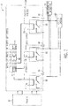
- the machinery protection monitoring system 38 may include an electronic board 46, which may further include a processor 48 that may be operatively coupled to a memory 50 to execute instructions for carrying out the presently disclosed techniques. These instructions may be encoded in programs or code stored in a tangible non-transitory computer-readable medium, such as the memory 50 and/or other storage.
- the processor 48 may be a general purpose processor, system-on-chip (SoC) device, an application-specific integrated circuit (ASIC), or some other processor configuration.
- the processor 48 may receive the sensor 42 data (e.g., pressure and temperature of the compressor 20, speed and temperature of the turbine 26, vibration of the compressor 20 and the turbine 26, CO 2 levels in the exhaust gas 36, carbon content in the fuel 31, temperature of the fuel 31, temperature, pressure, clearance of the compressor 20 and the turbine 26, flame temperature or intensity, vibration, and combustion dynamics of the combustion system 22, load data from load 34, and so forth), and may use the sensor 42 data as part of one or more protection functionalities to monitor and protect the operational health of, for example, the fuel system 16, the compressor 20, the turbine 26, combustion system 22, the exhaust section 28, or other components that may be included in the industrial system 10.
- the machinery protection monitoring system 38 may be a Bently Nevada 3500 Series Machinery Monitoring SystemTM, available from General Electric Co. of Schenectady, New York.
- the electronic board 46 of the machinery protection monitoring system 38 may include a number of respective monitors for monitoring respective operating inputs and/or outputs.
- the respective monitors may each occupy respective slots in a rack of the protection monitoring system 38.
- the processor 48 may provide user-adjustable protection and/or control setpoints for each of a number of input and/or output channels of the protection monitoring system 38, and generate and transmit alarm signals to one or more relays 52, 54, and 56.
- the alarm signals may also be passed to one or more front-panel indicators 64, 66, and 68 (e.g., light-emitting diodes (LEDs)), facilitating, for example, plant operator or technician observation.
- LEDs light-emitting diodes
- the processor 48 may provide proportional 4 to 20 milliamp (mA) outputs for each of the number of channels of the protection monitoring system 38 via the relays 52, 54, and 56 to the control system 40. Based on these outputs, the control system 40 may provide outputs to transducers or other final control elements (e.g., valves, actuators, etc.).
- mA milliamp
- the protection monitoring system 38 may be programmed or configurable (e.g., performed via the processor 48 and the memory 50) to support a number of protection functions, and to be responsive to a number of detected operating conditions of the industrial system 10.
- the machinery protection monitoring system 38 may include a fault detection and management system useful in detecting (e.g., via sensors 42), isolating (e.g., tripping one or more final control elements that may be coupled to the compressor 20 or the turbine 26), and monitoring and/or compensating for one or more adverse operating conditions of the industrial system 10 (e.g., speed, temperature, pressure, vibration, flow, fuel consumption, power production, clearance).
- one or more sets of protection and/or monitoring functions may be temporarily inhibited or suspended by, for example, plant personnel (e.g., operators, technicians, engineers, contractors, and so forth) servicing one or more components (e.g., the compressor 20, the turbine 26, the combustors 22, the load 34, and so forth) of the industrial system 10.
- the one or more sets of protection and/or monitoring functions may also be temporarily inhibited by, for example, plant personnel manually placing the protection monitoring system 38 in an inhibit mode (e.g., during start-up or the transient operational state of the turbine 26 or during a time in which a component associated with the turbine 26 may be in disrepair), and then inadvertently leaving the protection monitoring system 38 in the inhibit mode.
- plant personnel e.g., operators, technicians, engineers, contractors, and so forth
- the one or more sets of protection and/or monitoring functions may also be temporarily inhibited by, for example, plant personnel manually placing the protection monitoring system 38 in an inhibit mode (e.g., during start-up or the trans
- the protection monitoring system 38 may be useful to program and/or configure (e.g., via the processor 48 and the memory 50) the protection monitoring system 38 to automatically control the inhibition or temporary suspension of the protection functions by way of alarm escalation rule-based functions.
- the processor 48 may generate and transmit alarm signals to the relays 52, 54, and 56) to indicate whether or not a fault (e.g., electrical fault, code related error, or other error) has occurred based on, for example, the one or more alarm escalation rule-based functions.
- a fault e.g., electrical fault, code related error, or other error
- the relays 52 may include, for example, single-pole double-throw (SPDT) relays, double-pole double-throw (DPDT) relays, or any electronic relay devices that may be energized based on control signals received from the processor 48 to operate (e.g., close and/or open) respective contacts 58, 60, and 62 to perform one or more control actions (e.g., signal an alarm, an alert, or other notification via the control system 40, the HMI operator interface 44, or the panel indicators 64, 66, and 68).
- SPDT single-pole double-throw
- DPDT double-pole double-throw
- control actions e.g., signal an alarm, an alert, or other notification via the control system 40, the HMI operator interface 44, or the panel indicators 64, 66, and 68.
- the protection monitoring system 38 may provide indications of whether or not a fault has occurred based on, for example, the one or more alarm escalation rule-based functions.
- the alarm escalation rule-based functions may include one or more sets of iterative alarm escalation rules (e.g., stored in the memory 50) that may be predetermined or adjustable (e.g., user-configurable), and may be based on, for example, machine speed (e.g., compressor 20 speed, turbine 26, and so forth), machine mode of operation (e.g., turbine 26 trip multiply mode of operation), a predetermined or adjustable timing sequence (e.g., timer), or other similar operational characteristic.
- machine speed e.g., compressor 20 speed, turbine 26, and so forth
- machine mode of operation e.g., turbine 26 trip multiply mode of operation
- a predetermined or adjustable timing sequence e.g., timer
- the protection monitoring system 38 may include alarm escalation rules according to a predetermined operational parameter range (e.g., speed range, a pressure range, a temperature range, a vibration range, a flow range, a frequency range, a clearance range, and so forth).
- a predetermined operational parameter range e.g., speed range, a pressure range, a temperature range, a vibration range, a flow range, a frequency range, a clearance range, and so forth.
- the protection monitoring system 38 may be programmed or conditioned to generate an alarm signal, or a number of alarm signals according to the alarm escalation level, when one or more components of the industrial system 10 is operating outside of the predetermined operating parameter range.
- the protection monitoring system 38 may include an alarm escalation rule to automatically shift (e.g., increase or decrease depending on the specific application) normal operating protection and/or control setpoints for compressor 20 and/or turbine 26 vibrations (e.g., between approximately 3 mils of vibration and 6 mils of vibration), turbine 26 speed (e.g., between approximately 5,000 revolutions per minute (rpm) and 17,500 rpm), compressor 20 pressure (e.g., between approximately 1000 pounds per square inch (psi) and 18,000 psi), turbine 26 and exhaust section 28 temperature (e.g., between approximately 300° C and 600° C), combustors 22 flame intensity, air 30 to fuel 31 ratio (AFR), and so forth, to compensate for certain transient operating conditions (e.g., during start-up or commissioning of components of the compressor 20 or the turbine 26).
- an alarm escalation rule to automatically shift (e.g., increase or decrease depending on the specific application) normal operating protection and/or control setpoints for compressor 20 and/or turbine 26 vibrations (
- the programmed protection setpoints of the protection monitoring system 38 may be temporarily adjusted (e.g., manually by a plant operator or automatically) to allow the turbine 26 to transition from the transient operating conditions during ignition or commissioning to the steady-state normal operating conditions.
- these techniques may be performed to allow the turbine 26 to pass through the speed that may be the same as the structural resonance of the turbine 26.
- the processor 48 may generate an attention signal (e.g., a signal to relay 52 and indicator 64) and a user inhibit alarm signal (e.g., a notification that plant personnel has temporarily suspended a protection function of the protection monitoring system 38), and may then escalate to generating a protection faulted alarm signal (e.g., a notification that a fault or other adverse operating effect has occurred) when the processor 48 determines after some period of time that the turbine 26 has been operating outside of the predetermined speed range.
- an attention signal e.g., a signal to relay 52 and indicator 64
- a user inhibit alarm signal e.g., a notification that plant personnel has temporarily suspended a protection function of the protection monitoring system 38
- a protection faulted alarm signal e.g., a notification that a fault or other adverse operating effect has occurred
- the protection monitoring system 38 may indicate whether or not a fault has occurred based on a timer (e.g., user-configurable time limit expressed in hours, minutes, seconds, and so forth) alarm escalation rule. For example, upon detection that an inhibit protection function has been enabled (e.g., due to a possible fault or due to manual inhibition or temporary suspension of the protection function performed by plant personnel), the protection monitoring system 38 may initiate a countdown timer or count-up timer, for example. If the protection function is not reengaged within the specified time period, the processor 48 of the protection monitoring system 38 may indicate that a fault (e.g., electrical fault, code related error, or other error) has occurred via the relay 56 and panel indicator 68.
- a timer e.g., user-configurable time limit expressed in hours, minutes, seconds, and so forth
- the protection monitoring system 38 may indicate whether or not a fault has occurred based on a mode of operation escalation rule.
- the processor 48 may indicate that a fault has occurred based on whether a trip multiply function (e.g., a temporarily increased in magnitude of the control setpoints by a predetermined integer factor) of the protection monitoring system 38 has been activated.
- a trip multiply function e.g., a temporarily increased in magnitude of the control setpoints by a predetermined integer factor
- the protection monitoring system 38 may automatically transmit a signal to energize the relay 52 and attention indicator 64 and the relay 54 and the user inhibit relay indicator 66.
- the relay 52 and the attention indicator 64 may, in some embodiments, represent a first level of the escalation process.
- the relay 52 and the attention indicator 64 may be energized to alert a plant operator or engineer (e.g., via the HMI operator interface) that either inhibit function has been invoked, or that some other event or action by plant personnel has occurred at the protection monitoring system 38.
- the relay 54 and the user inhibit relay indicator 66 may be energized may be specifically indicate that a protection inhibit function has been enabled.
- the processor 48 may transmit a signal to energize the relay 54 to indicate an inhibition of a rack alarm inhibit, a special alarm inhibit, a channel bypass, an alert inhibit, a danger inhibit, trip multiply mode of operation, and so forth.
- the processor 48 of the protection monitoring system 38 may then escalate, for example, when an escalation rule is satisfied, in which the processor 48 of the protection monitoring system 38 may transmit an signal to the relay 56 and the protection faulted indicator 68 to indicate the presence of a fault (e.g., electrical fault, code related error, or other error) on one or more components of the industrial system 10 such as the compressor 20, the turbine 26, or other components of the turbine system 10.
- the processor 48 of the protection monitoring system 38 may transmit one or more alarm signals to the relays 52, 54, and 56 to initiate one or more actions such as, for example, signaling an alarm, generating an alert, or generating some other notification via the control system 40, the HMI operator interface 44, or the panel indicators 64, 66, and 68.
- the protection monitoring system 38 may substantially reduce any possibility of the protection functions of the protection monitoring system 38 being inadvertently left inhibited and/or temporarily suspended, and, by extension, may reduce any possibility of components (e.g., the compressor 20, the turbine 26, the combustors 22, the load 34, and so forth) of the industrial system 10 operating while in an unprotected state or under other adverse conditions.
- components e.g., the compressor 20, the turbine 26, the combustors 22, the load 34, and so forth
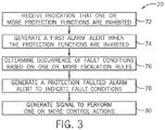
- FIG. 3 a flow diagram is presented, illustrating an embodiment of a process 70 useful in automatically signaling that protection functions of the machine protection monitoring system 38 has been inhibited or temporarily suspended according to an alarm escalation mechanism utilized, for example, the processor 48 depicted in FIG. 2 .
- the process 70 may include code or instructions stored in a non-transitory computer-readable medium (e.g., the memory 50) and executed, for example, by the one or more processors 48 included in the protection monitoring system 38.
- the process 70 may begin with the processor 48 receiving (block 72) an indication that one or more protection functions have been inhibited or temporarily suspended.
- one or more sets of protection and/or monitoring functions may be temporarily inhibited or suspended by, for example, plant personnel (e.g., operators, technicians, contractors) that may be servicing one or more components (e.g., the compressor 20, the turbine 26, the combustors 22, the load 34, and so forth) of the industrial system 10.
- plant personnel e.g., operators, technicians, contractors
- components e.g., the compressor 20, the turbine 26, the combustors 22, the load 34, and so forth
- the process 70 may then continue with the processor 48 generating (block 74) an alarm as an indication that one or more protection functions have been inhibited or temporarily suspended.
- the processor 48 may generate a signal to energize the relay 52 and attention indicator 64 and the relay 54 and the user inhibit relay indicator 66 to indicate via the control system 40 and/or the HMI operator interface 44, for example, a rack alarm inhibit, a special alarm inhibit, a channel bypass, an alert inhibit, a danger inhibit, trip multiply mode of operation, and so forth.
- the process 70 may then continue with the processor 48 determining (block 76) an occurrence of fault operating conditions based on one or more alarm escalation rules.
- the processor 48 may determine whether a fault has occurred based on, for example, machine speed (e.g., compressor 20 speed, turbine 26, and so forth), machine mode of operation (e.g., turbine 26 trip multiply mode of operation), based on a predetermined or adjustable timing sequence (e.g., timer), or other similar operational characteristic.
- machine speed e.g., compressor 20 speed, turbine 26, and so forth
- machine mode of operation e.g., turbine 26 trip multiply mode of operation
- a predetermined or adjustable timing sequence e.g., timer
- the process 70 may then continue with the processor 48 generating (block 78) a protection faulted alarm signal when one or more of the alarm escalation rules are satisfied.
- the processor 48 may generate a signal to energize the relay 56 and the protection faulted indicator 68, indicating via the control system 40 and/or the HMI operator interface 44, for example, that one or more components of the turbine system is operating in an unprotected and/or unmonitored state.
- the process 70 may then conclude with the processor 48 generating (block 80) and transmitting a signal as an indication to perform one or more control actions (e.g., by way of a transducer, actuator, valve, and so forth) to, for example, respond to the fault operating conditions and/or to automatically reengage the protection functions of the protection monitoring system 38 previously inhibited.
- the protection monitoring system 38 may substantially reduce any possibility of the protection functions of the protection monitoring system 38 being inadvertently left inhibited and/or temporarily suspended, and, by extension, reduce any possibility of components (e.g., the compressor 20, the turbine 26, the combustors 22, the load 34, and so forth) of the industrial system 10 operating while in an unprotected state or under other adverse conditions.
- the protection monitoring system may generate and transmit signals to energize a number of relays to indicate whether or not a fault or other adverse operating condition on one or more industrial machines (e.g., compressor, turbine, and so forth) of an industrial system has occurred.
- the protection monitoring system may indicate whether or not the fault has occurred based on, for example, a set of alarm escalation rules.
- the set of alarm escalation rules may include a predetermined or user-configurable operational parameter range that the industrial machine is expected to operate within, a predetermined or user-configurable time limit for the user-invoked inhibition or temporary suspension of the protection functions, or determinable mode of operation the industrial machine is expected to operate according thereto.
- the protection monitoring system may substantially reduce any possibility of the protection functions of the protection monitoring system being inadvertently left inhibited and/or temporarily suspended by the user, and, by extension, may reduce any possibility of the industrial machines of the industrial system operating while in an unprotected state or under other adverse conditions.
Landscapes
- Physics & Mathematics (AREA)
- General Physics & Mathematics (AREA)
- Business, Economics & Management (AREA)
- Emergency Management (AREA)
- Engineering & Computer Science (AREA)
- Automation & Control Theory (AREA)
- Testing And Monitoring For Control Systems (AREA)
Applications Claiming Priority (2)
| Application Number | Priority Date | Filing Date | Title |
|---|---|---|---|
| US14/271,104 US9406174B2 (en) | 2014-05-06 | 2014-05-06 | Systems and methods for monitoring protection devices of an industrial machine |
| PCT/US2015/018934 WO2015171197A1 (en) | 2014-05-06 | 2015-03-05 | Systems and methods for monitoring protection devices of an industrial machine |
Publications (2)
| Publication Number | Publication Date |
|---|---|
| EP3140700A1 EP3140700A1 (en) | 2017-03-15 |
| EP3140700B1 true EP3140700B1 (en) | 2021-02-17 |
Family
ID=52697542
Family Applications (1)
| Application Number | Title | Priority Date | Filing Date |
|---|---|---|---|
| EP15711361.4A Active EP3140700B1 (en) | 2014-05-06 | 2015-03-05 | Systems and methods for monitoring protection devices of an industrial machine |
Country Status (4)
| Country | Link |
|---|---|
| US (4) | US9406174B2 (da) |
| EP (1) | EP3140700B1 (da) |
| DK (1) | DK3140700T3 (da) |
| WO (1) | WO2015171197A1 (da) |
Families Citing this family (15)
| Publication number | Priority date | Publication date | Assignee | Title |
|---|---|---|---|---|
| WO2017052578A1 (en) | 2015-09-25 | 2017-03-30 | Intel Corporation | Alert system for internet of things (iot) devices |
| US20180016992A1 (en) * | 2016-07-12 | 2018-01-18 | General Electric Company | Neural network for combustion system flame detection |
| US10677170B2 (en) * | 2016-08-05 | 2020-06-09 | Pratt & Whitney Canada Corp. | Apparatus and method for detecting a threshold vibration condition in a gas turbine engine |
| US10151216B2 (en) | 2016-08-31 | 2018-12-11 | General Electric Technology Gmbh | Insulation quality indicator module for a valve and actuator monitoring system |
| US10626749B2 (en) | 2016-08-31 | 2020-04-21 | General Electric Technology Gmbh | Spindle vibration evaluation module for a valve and actuator monitoring system |
| US10871081B2 (en) | 2016-08-31 | 2020-12-22 | General Electric Technology Gmbh | Creep damage indicator module for a valve and actuator monitoring system |
| US10066501B2 (en) | 2016-08-31 | 2018-09-04 | General Electric Technology Gmbh | Solid particle erosion indicator module for a valve and actuator monitoring system |
| US10156153B2 (en) | 2016-08-31 | 2018-12-18 | General Electric Technology Gmbh | Advanced tightness test evaluation module for a valve and actuator monitoring system |
| US10544700B2 (en) | 2016-08-31 | 2020-01-28 | General Electric Technology Gmbh | Advanced startup counter module for a valve and actuator monitoring system |
| US10233786B2 (en) | 2017-03-28 | 2019-03-19 | General Electric Technology Gmbh | Actuator spring lifetime supervision module for a valve and actuator monitoring system |
| WO2018184130A1 (en) * | 2017-04-03 | 2018-10-11 | Honeywell International Inc. | Alarm and notification generation devices, methods, and systems |
| US20190195695A1 (en) * | 2017-08-30 | 2019-06-27 | Walmart Apollo, Llc | Temperature environmental sensors on pallet |
| US20200133254A1 (en) * | 2018-05-07 | 2020-04-30 | Strong Force Iot Portfolio 2016, Llc | Methods and systems for data collection, learning, and streaming of machine signals for part identification and operating characteristics determination using the industrial internet of things |
| US10446014B1 (en) * | 2018-06-27 | 2019-10-15 | Bently Nevada, Llc | Alarm notification delay |
| EP3909223B1 (en) | 2019-01-13 | 2024-08-21 | Strong Force Iot Portfolio 2016, LLC | Monitoring and managing industrial settings |
Family Cites Families (8)
| Publication number | Priority date | Publication date | Assignee | Title |
|---|---|---|---|---|
| US5870317A (en) * | 1997-05-21 | 1999-02-09 | Barnett; Ralph L. | Remote and proximal interlock testing mechanisms and testing systems |
| US5920263A (en) * | 1998-06-11 | 1999-07-06 | Ohmeda, Inc. | De-escalation of alarm priorities in medical devices |
| US6687649B2 (en) | 2001-04-30 | 2004-02-03 | Schneider Automation Inc. | System, method and computer program for a synoptic interlock prompting and input override system with a maintenance log |
| US20070088572A1 (en) * | 2005-10-14 | 2007-04-19 | General Electric Company | System and method for alert escalation processing in healthcare information systems |
| US20090031631A1 (en) | 2007-07-31 | 2009-02-05 | Prastel S.P.A. | Automated closing system with remote control of the force |
| US8648706B2 (en) * | 2010-06-24 | 2014-02-11 | Honeywell International Inc. | Alarm management system having an escalation strategy |
| US8659415B2 (en) | 2011-07-15 | 2014-02-25 | General Electric Company | Alarm management |
| WO2013063262A1 (en) * | 2011-10-25 | 2013-05-02 | Hydrotech, Inc | Pump monitoring device |
-
2014
- 2014-05-06 US US14/271,104 patent/US9406174B2/en active Active
-
2015
- 2015-03-05 WO PCT/US2015/018934 patent/WO2015171197A1/en not_active Ceased
- 2015-03-05 EP EP15711361.4A patent/EP3140700B1/en active Active
- 2015-03-05 DK DK15711361.4T patent/DK3140700T3/da active
-
2016
- 2016-07-25 US US15/218,765 patent/US9672664B2/en active Active
-
2017
- 2017-06-05 US US15/613,460 patent/US10157506B2/en active Active
-
2018
- 2018-11-28 US US16/203,208 patent/US10650613B2/en active Active
Non-Patent Citations (1)
| Title |
|---|
| None * |
Also Published As
| Publication number | Publication date |
|---|---|
| US20170337751A1 (en) | 2017-11-23 |
| US9672664B2 (en) | 2017-06-06 |
| US20190139325A1 (en) | 2019-05-09 |
| DK3140700T3 (da) | 2021-04-12 |
| US10157506B2 (en) | 2018-12-18 |
| US20150325060A1 (en) | 2015-11-12 |
| US10650613B2 (en) | 2020-05-12 |
| WO2015171197A1 (en) | 2015-11-12 |
| EP3140700A1 (en) | 2017-03-15 |
| US20160335811A1 (en) | 2016-11-17 |
| US9406174B2 (en) | 2016-08-02 |
Similar Documents
| Publication | Publication Date | Title |
|---|---|---|
| US10650613B2 (en) | Systems and methods for monitoring protection devices of an industrial machine | |
| US10962448B2 (en) | Method for monitoring the engines of an aircraft | |
| US8342794B2 (en) | Stall and surge detection system and method | |
| CN101881269B (zh) | 检测旋转式机器故障的系统 | |
| US10037026B2 (en) | Systems and methods for fault analysis | |
| EP2957010B1 (en) | Protection monitoring system with fault indicators | |
| CA2965066C (en) | Apparatus and method for detecting a threshold vibration condition in a gas turbine engine | |
| EP3103968A1 (en) | Systems and methods for monitoring a compressor | |
| US10954812B2 (en) | Gas turbine blade flutter monitoring and control system | |
| EP2378087B1 (en) | System and method for detecting failure in gas turbine | |
| WO2014113047A1 (en) | Method and system for predicting a life cycle of an engine | |
| US9500136B2 (en) | Systems and methods for generating variable ramp rates for turbomachinery | |
| EP2407642B1 (en) | System and method for determining steady state conditions in a gas turbine | |
| JPH10339663A (ja) | 回転装置の振動発生時に保護手段をトリガする方法 | |
| US20150338312A1 (en) | Systems and Methods for Implementing Engine Cycle Count | |
| CN104204470B (zh) | 用于燃气涡轮设备的安全的运行的方法和装置 | |
| EP3324258A1 (en) | Modeling to detect gas turbine anomalies | |
| JP4939889B2 (ja) | ガスタービン燃焼監視システムおよび燃焼監視方法 | |
| CN102252850B (zh) | 用于检测燃气涡轮机硬件中的故障的系统、方法和装置 |
Legal Events
| Date | Code | Title | Description |
|---|---|---|---|
| STAA | Information on the status of an ep patent application or granted ep patent |
Free format text: STATUS: THE INTERNATIONAL PUBLICATION HAS BEEN MADE |
|
| PUAI | Public reference made under article 153(3) epc to a published international application that has entered the european phase |
Free format text: ORIGINAL CODE: 0009012 |
|
| STAA | Information on the status of an ep patent application or granted ep patent |
Free format text: STATUS: REQUEST FOR EXAMINATION WAS MADE |
|
| 17P | Request for examination filed |
Effective date: 20161206 |
|
| AK | Designated contracting states |
Kind code of ref document: A1 Designated state(s): AL AT BE BG CH CY CZ DE DK EE ES FI FR GB GR HR HU IE IS IT LI LT LU LV MC MK MT NL NO PL PT RO RS SE SI SK SM TR |
|
| AX | Request for extension of the european patent |
Extension state: BA ME |
|
| DAV | Request for validation of the european patent (deleted) | ||
| DAX | Request for extension of the european patent (deleted) | ||
| STAA | Information on the status of an ep patent application or granted ep patent |
Free format text: STATUS: EXAMINATION IS IN PROGRESS |
|
| 17Q | First examination report despatched |
Effective date: 20190314 |
|
| GRAP | Despatch of communication of intention to grant a patent |
Free format text: ORIGINAL CODE: EPIDOSNIGR1 |
|
| STAA | Information on the status of an ep patent application or granted ep patent |
Free format text: STATUS: GRANT OF PATENT IS INTENDED |
|
| INTG | Intention to grant announced |
Effective date: 20200925 |
|
| GRAS | Grant fee paid |
Free format text: ORIGINAL CODE: EPIDOSNIGR3 |
|
| GRAA | (expected) grant |
Free format text: ORIGINAL CODE: 0009210 |
|
| STAA | Information on the status of an ep patent application or granted ep patent |
Free format text: STATUS: THE PATENT HAS BEEN GRANTED |
|
| AK | Designated contracting states |
Kind code of ref document: B1 Designated state(s): AL AT BE BG CH CY CZ DE DK EE ES FI FR GB GR HR HU IE IS IT LI LT LU LV MC MK MT NL NO PL PT RO RS SE SI SK SM TR |
|
| REG | Reference to a national code |
Ref country code: GB Ref legal event code: FG4D |
|
| REG | Reference to a national code |
Ref country code: CH Ref legal event code: EP |
|
| REG | Reference to a national code |
Ref country code: DE Ref legal event code: R096 Ref document number: 602015065545 Country of ref document: DE |
|
| REG | Reference to a national code |
Ref country code: AT Ref legal event code: REF Ref document number: 1362256 Country of ref document: AT Kind code of ref document: T Effective date: 20210315 |
|
| REG | Reference to a national code |
Ref country code: IE Ref legal event code: FG4D |
|
| REG | Reference to a national code |
Ref country code: DK Ref legal event code: T3 Effective date: 20210408 |
|
| REG | Reference to a national code |
Ref country code: SE Ref legal event code: TRGR |
|
| REG | Reference to a national code |
Ref country code: LT Ref legal event code: MG9D |
|
| REG | Reference to a national code |
Ref country code: NL Ref legal event code: MP Effective date: 20210217 |
|
| PG25 | Lapsed in a contracting state [announced via postgrant information from national office to epo] |
Ref country code: PT Free format text: LAPSE BECAUSE OF FAILURE TO SUBMIT A TRANSLATION OF THE DESCRIPTION OR TO PAY THE FEE WITHIN THE PRESCRIBED TIME-LIMIT Effective date: 20210617 Ref country code: LT Free format text: LAPSE BECAUSE OF FAILURE TO SUBMIT A TRANSLATION OF THE DESCRIPTION OR TO PAY THE FEE WITHIN THE PRESCRIBED TIME-LIMIT Effective date: 20210217 Ref country code: HR Free format text: LAPSE BECAUSE OF FAILURE TO SUBMIT A TRANSLATION OF THE DESCRIPTION OR TO PAY THE FEE WITHIN THE PRESCRIBED TIME-LIMIT Effective date: 20210217 Ref country code: GR Free format text: LAPSE BECAUSE OF FAILURE TO SUBMIT A TRANSLATION OF THE DESCRIPTION OR TO PAY THE FEE WITHIN THE PRESCRIBED TIME-LIMIT Effective date: 20210518 Ref country code: FI Free format text: LAPSE BECAUSE OF FAILURE TO SUBMIT A TRANSLATION OF THE DESCRIPTION OR TO PAY THE FEE WITHIN THE PRESCRIBED TIME-LIMIT Effective date: 20210217 Ref country code: BG Free format text: LAPSE BECAUSE OF FAILURE TO SUBMIT A TRANSLATION OF THE DESCRIPTION OR TO PAY THE FEE WITHIN THE PRESCRIBED TIME-LIMIT Effective date: 20210517 Ref country code: NO Free format text: LAPSE BECAUSE OF FAILURE TO SUBMIT A TRANSLATION OF THE DESCRIPTION OR TO PAY THE FEE WITHIN THE PRESCRIBED TIME-LIMIT Effective date: 20210517 |
|
| REG | Reference to a national code |
Ref country code: AT Ref legal event code: MK05 Ref document number: 1362256 Country of ref document: AT Kind code of ref document: T Effective date: 20210217 |
|
| PG25 | Lapsed in a contracting state [announced via postgrant information from national office to epo] |
Ref country code: RS Free format text: LAPSE BECAUSE OF FAILURE TO SUBMIT A TRANSLATION OF THE DESCRIPTION OR TO PAY THE FEE WITHIN THE PRESCRIBED TIME-LIMIT Effective date: 20210217 Ref country code: LV Free format text: LAPSE BECAUSE OF FAILURE TO SUBMIT A TRANSLATION OF THE DESCRIPTION OR TO PAY THE FEE WITHIN THE PRESCRIBED TIME-LIMIT Effective date: 20210217 Ref country code: PL Free format text: LAPSE BECAUSE OF FAILURE TO SUBMIT A TRANSLATION OF THE DESCRIPTION OR TO PAY THE FEE WITHIN THE PRESCRIBED TIME-LIMIT Effective date: 20210217 Ref country code: NL Free format text: LAPSE BECAUSE OF FAILURE TO SUBMIT A TRANSLATION OF THE DESCRIPTION OR TO PAY THE FEE WITHIN THE PRESCRIBED TIME-LIMIT Effective date: 20210217 |
|
| PG25 | Lapsed in a contracting state [announced via postgrant information from national office to epo] |
Ref country code: IS Free format text: LAPSE BECAUSE OF FAILURE TO SUBMIT A TRANSLATION OF THE DESCRIPTION OR TO PAY THE FEE WITHIN THE PRESCRIBED TIME-LIMIT Effective date: 20210617 |
|
| PG25 | Lapsed in a contracting state [announced via postgrant information from national office to epo] |
Ref country code: SM Free format text: LAPSE BECAUSE OF FAILURE TO SUBMIT A TRANSLATION OF THE DESCRIPTION OR TO PAY THE FEE WITHIN THE PRESCRIBED TIME-LIMIT Effective date: 20210217 Ref country code: AT Free format text: LAPSE BECAUSE OF FAILURE TO SUBMIT A TRANSLATION OF THE DESCRIPTION OR TO PAY THE FEE WITHIN THE PRESCRIBED TIME-LIMIT Effective date: 20210217 Ref country code: EE Free format text: LAPSE BECAUSE OF FAILURE TO SUBMIT A TRANSLATION OF THE DESCRIPTION OR TO PAY THE FEE WITHIN THE PRESCRIBED TIME-LIMIT Effective date: 20210217 Ref country code: CZ Free format text: LAPSE BECAUSE OF FAILURE TO SUBMIT A TRANSLATION OF THE DESCRIPTION OR TO PAY THE FEE WITHIN THE PRESCRIBED TIME-LIMIT Effective date: 20210217 |
|
| REG | Reference to a national code |
Ref country code: DE Ref legal event code: R097 Ref document number: 602015065545 Country of ref document: DE |
|
| PG25 | Lapsed in a contracting state [announced via postgrant information from national office to epo] |
Ref country code: MC Free format text: LAPSE BECAUSE OF FAILURE TO SUBMIT A TRANSLATION OF THE DESCRIPTION OR TO PAY THE FEE WITHIN THE PRESCRIBED TIME-LIMIT Effective date: 20210217 Ref country code: ES Free format text: LAPSE BECAUSE OF FAILURE TO SUBMIT A TRANSLATION OF THE DESCRIPTION OR TO PAY THE FEE WITHIN THE PRESCRIBED TIME-LIMIT Effective date: 20210217 Ref country code: SK Free format text: LAPSE BECAUSE OF FAILURE TO SUBMIT A TRANSLATION OF THE DESCRIPTION OR TO PAY THE FEE WITHIN THE PRESCRIBED TIME-LIMIT Effective date: 20210217 Ref country code: RO Free format text: LAPSE BECAUSE OF FAILURE TO SUBMIT A TRANSLATION OF THE DESCRIPTION OR TO PAY THE FEE WITHIN THE PRESCRIBED TIME-LIMIT Effective date: 20210217 |
|
| REG | Reference to a national code |
Ref country code: BE Ref legal event code: MM Effective date: 20210331 |
|
| PLBE | No opposition filed within time limit |
Free format text: ORIGINAL CODE: 0009261 |
|
| STAA | Information on the status of an ep patent application or granted ep patent |
Free format text: STATUS: NO OPPOSITION FILED WITHIN TIME LIMIT |
|
| 26N | No opposition filed |
Effective date: 20211118 |
|
| PG25 | Lapsed in a contracting state [announced via postgrant information from national office to epo] |
Ref country code: AL Free format text: LAPSE BECAUSE OF FAILURE TO SUBMIT A TRANSLATION OF THE DESCRIPTION OR TO PAY THE FEE WITHIN THE PRESCRIBED TIME-LIMIT Effective date: 20210217 Ref country code: LU Free format text: LAPSE BECAUSE OF NON-PAYMENT OF DUE FEES Effective date: 20210305 Ref country code: FR Free format text: LAPSE BECAUSE OF NON-PAYMENT OF DUE FEES Effective date: 20210417 Ref country code: IE Free format text: LAPSE BECAUSE OF NON-PAYMENT OF DUE FEES Effective date: 20210305 |
|
| PG25 | Lapsed in a contracting state [announced via postgrant information from national office to epo] |
Ref country code: SI Free format text: LAPSE BECAUSE OF FAILURE TO SUBMIT A TRANSLATION OF THE DESCRIPTION OR TO PAY THE FEE WITHIN THE PRESCRIBED TIME-LIMIT Effective date: 20210217 |
|
| PG25 | Lapsed in a contracting state [announced via postgrant information from national office to epo] |
Ref country code: IT Free format text: LAPSE BECAUSE OF FAILURE TO SUBMIT A TRANSLATION OF THE DESCRIPTION OR TO PAY THE FEE WITHIN THE PRESCRIBED TIME-LIMIT Effective date: 20210217 |
|
| PG25 | Lapsed in a contracting state [announced via postgrant information from national office to epo] |
Ref country code: IS Free format text: LAPSE BECAUSE OF FAILURE TO SUBMIT A TRANSLATION OF THE DESCRIPTION OR TO PAY THE FEE WITHIN THE PRESCRIBED TIME-LIMIT Effective date: 20210617 |
|
| PG25 | Lapsed in a contracting state [announced via postgrant information from national office to epo] |
Ref country code: BE Free format text: LAPSE BECAUSE OF NON-PAYMENT OF DUE FEES Effective date: 20210331 |
|
| PG25 | Lapsed in a contracting state [announced via postgrant information from national office to epo] |
Ref country code: HU Free format text: LAPSE BECAUSE OF FAILURE TO SUBMIT A TRANSLATION OF THE DESCRIPTION OR TO PAY THE FEE WITHIN THE PRESCRIBED TIME-LIMIT; INVALID AB INITIO Effective date: 20150305 |
|
| PG25 | Lapsed in a contracting state [announced via postgrant information from national office to epo] |
Ref country code: CY Free format text: LAPSE BECAUSE OF FAILURE TO SUBMIT A TRANSLATION OF THE DESCRIPTION OR TO PAY THE FEE WITHIN THE PRESCRIBED TIME-LIMIT Effective date: 20210217 |
|
| P01 | Opt-out of the competence of the unified patent court (upc) registered |
Effective date: 20230526 |
|
| PG25 | Lapsed in a contracting state [announced via postgrant information from national office to epo] |
Ref country code: MK Free format text: LAPSE BECAUSE OF FAILURE TO SUBMIT A TRANSLATION OF THE DESCRIPTION OR TO PAY THE FEE WITHIN THE PRESCRIBED TIME-LIMIT Effective date: 20210217 |
|
| PG25 | Lapsed in a contracting state [announced via postgrant information from national office to epo] |
Ref country code: TR Free format text: LAPSE BECAUSE OF FAILURE TO SUBMIT A TRANSLATION OF THE DESCRIPTION OR TO PAY THE FEE WITHIN THE PRESCRIBED TIME-LIMIT Effective date: 20210217 |
|
| PG25 | Lapsed in a contracting state [announced via postgrant information from national office to epo] |
Ref country code: MT Free format text: LAPSE BECAUSE OF FAILURE TO SUBMIT A TRANSLATION OF THE DESCRIPTION OR TO PAY THE FEE WITHIN THE PRESCRIBED TIME-LIMIT Effective date: 20210217 |
|
| PGFP | Annual fee paid to national office [announced via postgrant information from national office to epo] |
Ref country code: CH Payment date: 20250401 Year of fee payment: 11 |
|
| REG | Reference to a national code |
Ref country code: CH Ref legal event code: U11 Free format text: ST27 STATUS EVENT CODE: U-0-0-U10-U11 (AS PROVIDED BY THE NATIONAL OFFICE) Effective date: 20260401 |
|
| PGFP | Annual fee paid to national office [announced via postgrant information from national office to epo] |
Ref country code: SE Payment date: 20260219 Year of fee payment: 12 |
|
| PGFP | Annual fee paid to national office [announced via postgrant information from national office to epo] |
Ref country code: GB Payment date: 20260220 Year of fee payment: 12 |
|
| PGFP | Annual fee paid to national office [announced via postgrant information from national office to epo] |
Ref country code: DE Payment date: 20260219 Year of fee payment: 12 Ref country code: DK Payment date: 20260219 Year of fee payment: 12 |