EP3140842B1 - Kontaktvorrichtung eines anlasserschützes - Google Patents
Kontaktvorrichtung eines anlasserschützes Download PDFInfo
- Publication number
- EP3140842B1 EP3140842B1 EP15725778.3A EP15725778A EP3140842B1 EP 3140842 B1 EP3140842 B1 EP 3140842B1 EP 15725778 A EP15725778 A EP 15725778A EP 3140842 B1 EP3140842 B1 EP 3140842B1
- Authority
- EP
- European Patent Office
- Prior art keywords
- contact
- spring
- contact device
- compression spring
- plate
- Prior art date
- Legal status (The legal status is an assumption and is not a legal conclusion. Google has not performed a legal analysis and makes no representation as to the accuracy of the status listed.)
- Active
Links
Images


Classifications
-
- H—ELECTRICITY
- H01—ELECTRIC ELEMENTS
- H01H—ELECTRIC SWITCHES; RELAYS; SELECTORS; EMERGENCY PROTECTIVE DEVICES
- H01H50/00—Details of electromagnetic relays
- H01H50/54—Contact arrangements
- H01H50/56—Contact spring sets
-
- H—ELECTRICITY
- H01—ELECTRIC ELEMENTS
- H01H—ELECTRIC SWITCHES; RELAYS; SELECTORS; EMERGENCY PROTECTIVE DEVICES
- H01H1/00—Contacts
- H01H1/12—Contacts characterised by the manner in which co-operating contacts engage
- H01H1/14—Contacts characterised by the manner in which co-operating contacts engage by abutting
- H01H1/20—Bridging contacts
- H01H1/2008—Facilitate mounting or replacing contact bridge and pressure spring on carrier
-
- H—ELECTRICITY
- H01—ELECTRIC ELEMENTS
- H01H—ELECTRIC SWITCHES; RELAYS; SELECTORS; EMERGENCY PROTECTIVE DEVICES
- H01H50/00—Details of electromagnetic relays
- H01H50/16—Magnetic circuit arrangements
- H01H50/18—Movable parts of magnetic circuits, e.g. armature
- H01H50/20—Movable parts of magnetic circuits, e.g. armature movable inside coil and substantially lengthwise with respect to axis thereof; movable coaxially with respect to coil
-
- H—ELECTRICITY
- H01—ELECTRIC ELEMENTS
- H01H—ELECTRIC SWITCHES; RELAYS; SELECTORS; EMERGENCY PROTECTIVE DEVICES
- H01H50/00—Details of electromagnetic relays
- H01H50/16—Magnetic circuit arrangements
- H01H50/18—Movable parts of magnetic circuits, e.g. armature
- H01H50/30—Mechanical arrangements for preventing or damping vibration or shock, e.g. by balancing of armature
-
- H—ELECTRICITY
- H01—ELECTRIC ELEMENTS
- H01H—ELECTRIC SWITCHES; RELAYS; SELECTORS; EMERGENCY PROTECTIVE DEVICES
- H01H51/00—Electromagnetic relays
- H01H51/02—Non-polarised relays
- H01H51/04—Non-polarised relays with single armature; with single set of ganged armatures
- H01H51/06—Armature is movable between two limit positions of rest and is moved in one direction due to energisation of an electromagnet and after the electromagnet is de-energised is returned by energy stored during the movement in the first direction, e.g. by using a spring, by using a permanent magnet, by gravity
- H01H51/065—Relays having a pair of normally open contacts rigidly fixed to a magnetic core movable along the axis of a solenoid, e.g. relays for starting automobiles
-
- H—ELECTRICITY
- H01—ELECTRIC ELEMENTS
- H01H—ELECTRIC SWITCHES; RELAYS; SELECTORS; EMERGENCY PROTECTIVE DEVICES
- H01H2235/00—Springs
- H01H2235/01—Spiral spring
Definitions
- the present invention relates to the field of starters for heat engines, in particular for motor vehicles, and more specifically to contactors for starters which supply power to the electric motor driving the starter pinion.
- the contactors of the starters of the state of the art have two roles, on the one hand to move the launcher supporting the pinion by means of a fork so as to allow the gear of the pinion to the crown of the heat engine to be started and on the other hand, supplying the electric starter motor to drive the pinion in rotation.
- the contactors include a set of coils making it possible to move the movable part of a magnetic core, the movable part of the magnetic core causing both the displacement of the fork and the displacement of a contact device comprising a plate of contact intended to establish electrical contact between supply terminals of the electric motor.
- crushing spring and return spring springs are placed on either side of the plate so as to force the plate against the terminals when the coils are activated and move the plate towards the terminals and to facilitate the return of the plate to its initial position when the coils are no longer supplied.
- contact devices of the state of the art generally include a large number of parts, which results in complex assembly.
- the patent application FR2957711 discloses a contact device for a starter contactor according to the preamble of claim 1. It is in particular known from this patent application means for mounting the rod assembly, springs and stops. For example, in this patent application, there are arrangements with stops mounted on the rod to retain a crushing spring. In one embodiment, there is disclosed a bayonet type washer mounted on the contact rod. This embodiment requires producing an axis with a flattened shoulder and a groove.
- This embodiment is therefore complex to implement.
- Other embodiments are described to solve this complex mounting problem as well as a shank without a shoulder.
- the assembly comprises a claw washer mounted on the contact rod, however with such an embodiment there is a risk with many cycles of use such as for reinforced starters, (that is to say a starter which starts a heat engine which is extinguished voluntarily when the vehicle is stopped, for example a red light) which requires a number of cycles four times higher than 'with a so-called standard starter that the claw washer breaks or recedes towards the fixed core leaving play with the crushing spring causing a malfunction of the starter. Indeed, in such a case, the crushing spring may no longer be functional and therefore no longer ensure contact between the contact plate and the terminals.
- an embodiment in which a pin is added in the axis to hold a washer forming the stop of the crushing spring.
- such an embodiment is complex to put in place due to the insertion by force into the shaft of a pin which can break during assembly.
- such an assembly cannot allow the contact rod to rest on the fixed core. In fact, with such an embodiment in the rest state, it is the wafer which is pressing on the fixed core which can cause it to deform.
- the spring for crushing the plate against the terminals can be offset with respect to the rod, causing an imbalance of the forces of the spring on the plate against the terminals.
- the aim of the invention is therefore to provide an inexpensive solution having a simple mounting of the contact device making it possible to reduce the appearance of rebounds when the coils are supplied and when the wafer is moved towards the terminals.
- the contact device must be reliable to allow the various elements to be held in position even after a large number of starts.
- the closing clip is in abutment on a closing collar of the contact rod.
- the closure clip comprises a first peripheral centering edge configured to come at least partially surround the closure collar so as to maintain the closure clip in position around the contact rod.
- the closure clip includes a centering peripheral edge configured to be at least partially surrounded by the end of the squeeze spring to keep said squeeze spring centered around the contact rod. This helps to keep the spring centered on the contact rod better.
- the closing clip comprising on each side two peripheral centering edges, one configured to be surrounded at least partially by the end of the crushing spring to keep said crushing spring centered around the contact rod and one to come at least partially surround the closure flange so as to hold the closure clip in position around the contact rod. This ensures good centering of the spring on the contact rod to avoid contact, for example, between the spring and the fixed core.
- the closing clip is symmetrical. This allows it to be mounted in either direction for easy mounting.
- the closure collar is integral with the contact rod.
- the retaining collar is integral with the contact rod.
- the crush spring is in contact with the contact pad.
- the crushing spring comprises a coil at the end of the crushing spring in contact with the contact plate, this coil comprising a portion of flat surface perpendicular to the axis of revolution of the crush spring.
- the closing clip and the contact plate apply a prestress of 45N +/- 10% on the crushing spring.
- the return spring is held by friction around one end of the contact rod and comes to bear on the retaining collar.
- the diameter of the hole in the contact plate is greater than the diameter of the closure collar and less than the diameter of the retaining collar.
- the crushing spring has a greater stiffness than the return spring.
- the present invention also relates to a starter comprising a contact device.
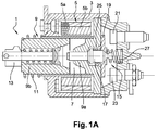
- the figures 1A and 1B show a diagram of a starter contactor 1 comprising a cover 3 enclosing a set of coils 5.
- the set of coils 5 defines at its center a tubular chamber 7 in which is arranged a magnetic core 9.
- the magnetic core 9 comprises a part fixed 9a and a movable part 9b which can move in translation, under the effect of the set of coils 5, between a rest position shown in figure 1 and an active position in which the movable part 9b comes into contact with the fixed part 9a of the magnetic core 9.
- a helical spring 11 promotes the return to the rest position in the absence of supply to the set of coils 5.
- the set of coils 5 comprises a take-up coil 5a and a contact coil 5b, the two coils 5a and 5b being supplied to move the movable part 9b of the magnetic core 9 from its rest position to its active position and then the maintenance in the active position of the moving part 9b is provided by the single contact coil 5b so as to limit the consumption of the set of coils 5.
- the movable part 9b of the magnetic core 9 is connected to a fork 13 (shown partially) which drives the movement of a pinion starter (not shown) from the starter towards the ring gear (not shown) of the heat engine to be started when the movable part 9b of the magnetic core 9 moves to its active position.
- the movement of the movable part 9b of the magnetic core 9 in the active position causes the movement in translation with respect to the cover 3 of a contact rod 17 of a contact device 15 between a rest position shown in FIG. figure 1 and an active position.
- the contact device 15 comprises a contact rod 17 provided with a collar of maintenance 17a integral in translation with the contact rod 17 and a contact plate 19 mounted on the contact rod 17.
- the passage into the active position of the contact rod 17 brings about the contacting of the contact plate 19 with at least an electric terminal.
- the contact plate 19 comes into contact with two electrical terminals 21 and 23 to supply the electric motor (not shown) driving the rotation of the pinion.
- the contact plate 19 is movable relative to the contact rod 17 between an initial position in which the contact rod 17 is in a rest position and a final position in which the contact rod 17 is in the active position. . In the initial position, the contact plate 19 is in contact with the retaining collar 17a and in the final position, a clearance is formed between the retaining collar 17a and the contact plate 19 due to the contact with the electrical terminals 21 and 23 .
- the contact device 15 also comprises a crushing spring 25 mounted on the contact rod 17 which is positioned around a portion of the contact rod 17 and intended to compress when the contact plate 19 comes into contact with it. the electrical terminals 21 and 23 and a return spring 27 intended to facilitate the return of the contact device 15 to the rest position when the coils 5a and 5b are no longer supplied.
- a crushing spring 25 mounted on the contact rod 17 which is positioned around a portion of the contact rod 17 and intended to compress when the contact plate 19 comes into contact with it.
- the electrical terminals 21 and 23 and a return spring 27 intended to facilitate the return of the contact device 15 to the rest position when the coils 5a and 5b are no longer supplied.
- the plate in the rest position the plate is in contact with the fixed core.
- the stop 17B which is in contact with the fixed core. This prevents the plate from deforming when the spring 25 visible on the figure 2 pushes the pad to the rest position.
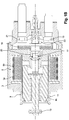
- the figure 2 shows an exploded view of a contact device 15 according to the invention.
- the contact device comprises a contact rod 17 made of an electrically insulating material, for example of a polymer material.
- Contact rod 17 includes a first radial surface forming a retaining flange 17a of a first diameter and a second radial surface forming a closing flange 17b of a second diameter smaller than the first diameter.
- the retaining 17a and closing 17b flanges are integral with the contact rod 17, that is to say made from material with the contact rod 17.
- the contact plate 19 is made of a conductive material, for example copper. , and comprises a central circular hole 19a, the diameter of which is greater than the diameter of the closing flange 17b and less than the diameter of the retaining flange 17a.
- the contact plate is mounted on the contact rod 17 by inserting the contact rod 17 into the hole 19a of the contact plate 19 as indicated by the arrow 29.
- the contact plate 19 then comes into contact with the collar. retaining 17a on a first side of the retaining collar 17a.
- the width of the plate is substantially equal to the diameter of the retaining collar 17a so that the retaining collar 17a substantially covers the width of the contact plate 19 which contributes to the stability of the contact plate 19.
- the spring d The crush 25 whose diameter is greater than the diameter of the hole 19a of the contact plate 19 is positioned around the contact rod 17 and comes into contact with the contact plate 17 as indicated by the arrow 31.
- the crushing spring 25 comprises at least one turn at its end, a portion of which comprises a flat surface perpendicular to the axis of revolution of the crushing spring 25.
- This flat surface is for example obtained by grinding at the end. of the spring in contact with the contact plate 19 so as to obtain a flat surface at the end of the crush spring 25 and increase the contact area between the crush spring 25 and the contact plate 19 and thus improve the stability of the contact plate 19 in particular during the passage into the active position of the contact rod 17.
- the contact device 15 also comprises a closing clip 33 whose radial width is greater than or equal to the diameter of the crushing spring 25 and in which a radial notch 33a is formed, the width of which is less than the diameter of the closing flange 17b and which is intended to receive a portion of the contact rod 17.
- the closing clip 33 is positioned around the contact rod 17 against the radial surface formed by the closing flange 17b, as shown by the arrow 35.
- the closing clip therefore comes between the crushing spring 25 and the flange. closing 17b of so as to hold the crush spring 25 and the contact plate 19 in position on the contact rod 17.
- the closing clip 33 is therefore mounted on the contact rod 17 after the contact plate 19 and the crushing spring 25, the assembly of the closing clip 33 necessitating the compression of the crushing spring 25 in order to be mounted on the rod. contact 17.
- the closing clip 33 then applies a preload on the crushing spring 25 which then applies a force on the contact plate 19 in the direction of the retaining flange 17a, which helps to keep the contact plate 19 as much as possible. on the retaining collar 17a.
- the crushing spring 25 can also comprise a coil comprising a flat portion perpendicular to the axis of revolution of the crushing spring 25 at its second end in contact with the closing clip 33 so as to increase the contact surface between the crushing spring 25 and the closing clip 33.
- the return spring 27 is positioned on the contact rod resting on a second side of the retaining collar opposite the first side as indicated by arrow 37.
- the internal diameter of the return spring 27 is slightly less than or substantially equal to the first side. diameter of the end of the contact rod 17 intended to receive the return spring 27 so that the friction between the return spring 27 and the contact rod 17 allow the return spring 27 to be held in position on the return rod contact 17, in particular before its installation in contactor 1.
- the return spring 27 may comprise, at least at one of its ends, a coil comprising a flat portion perpendicular to the axis of revolution of the return spring 27 so as to obtain a end with a flat surface and maximize the contact surface with the retaining collar 17a on one side and the cover 3 of the contactor 1 on the other.
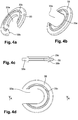
- closure clip will now be described in more detail from the figures 3a, 3b, 3c, 3d , 4a, 4b, 4c, 4d and 5 .
- the latter comprises a peripheral centering edge 33b on its face intended to come into contact with the closing flange 17b as shown in FIG. figure 3a, 3b, 3c, 3d .
- the peripheral centering edge 33b having a diameter slightly greater than the diameter of the closure flange 17b so as to be positioned around the latter while leaving a minimum clearance between the two.
- the closing clip 33 therefore at least partially surrounds the closing collar 17b.
- the closing clip 33 comprises a second peripheral centering edge 33c on its second face intended to be in contact with the crushing spring 25, the second peripheral centering edge 33c having a diameter slightly greater than the diameter of the crushing spring 25 so as to come at least partially surround the end of the crushing spring 25 while limiting the play between the latter and the closing clip 33.
- This second peripheral centering edge 33c makes it possible to keep the crushing spring 25 in a position centered around the contact rod 17.
- the two peripheral centering edges 33b and 33c may be different, for example in the case where the diameter of the crushing spring 25 and of the closing collar 17b are different but may also be identical in the case where the diameter of the crushing spring 25 and of the closing flange 17b are substantially identical so as to facilitate the manufacture of the clip of f closure 33 and reduce manufacturing costs.
- the figure 5 shows a section of the device, the closure clip 33 of which is according to the embodiment of the figure 4a to 4D , in the state mounted on the contact rod 17.
- the first peripheral centering edge 33b is positioned around the closing flange 17b and the second peripheral centering edge 33c is positioned in the center of the crushing spring 25 allowing thus maintaining and centering the crushing spring 25 around the contact rod 17.
- the crushing springs 25 and return springs 27 are generally helical springs metallic, for example steel.
- the stiffness of the squeeze spring 25 is greater than the stiffness of the return spring 27.
- the squeeze spring 25 is compressed between the contact pad 19 and the closing clip 33 so that 'in the rest state of the contact device 15, a prestress between 40N and 50N is applied to the crushing spring 25;
- the figure 6 shows a figure of the contact device 15 in the assembled state.
- This contact device 15 has only five parts: the contact rod 17, the return spring 27, the contact plate 19, the crushing spring 25 and the closing clip 33. This small number of parts makes it possible to reduce the load. cost of the device and make assembly simpler and faster, which also makes it possible to reduce assembly costs.
- the power supply to the set of coils 5 therefore causes the contact rod to move into the active position, which causes the contact plate to come into contact with the electrical terminals 21 and 23.
- the crushing spring 25 applies a force on the contact plate 19 at least 20 Newtons greater than the force exerted by the return spring spring 27 on the contact rod 17 due to the difference in stiffness between the crushing spring 25 and the return spring 27.
- the force exerted by the return spring 27 on the contact rod 17 is within a range of 25 to 40 Newtons.
- the force exerted by the crushing spring 25 on the contact plate 19 is for example 51 Newtons while the force exerted by the return spring 27 on the contact rod 17 is 28 Newtons.
- This greater force of the crushing spring 25 relative to the return spring 27 makes it possible to limit the play formed between the contact plate 19 and the retaining flange 17a in the final position of the contact plate 19, that is to say. ie at the time of contact with the electrical terminals 21 and 23.
- the rebound undergone by the contact plate 19 is therefore reduced when the contact rod 17 goes into the active position so that the power supply to the electric motor is carried out without qu 'there are false contacts.
- the coils 5a and 5b of the set of coils 5 are no longer supplied.
- the return spring 27 makes it possible to disconnect the contact plate 19 from the electrical terminals 21 and 25 so as to allow the return of the contact rod 17 to the rest position.
- a crushing spring 25 having a large diameter, a high number of turns, a turn comprising a flat portion perpendicular to its axis of revolution at at least one of its ends and the stiffness of which is greater than the stiffness of the return spring 27 makes it possible to obtain a more stable contact device when passing from the rest position to the active position when the contact plate 19 comes into contact with the electrical terminals 21 and 23 which makes it possible to greatly reduce or even eliminate the rebound effect due to the docking of the contact plate 19 on the electrical terminals 21 and 23 or due to the balancing of the crushing spring 25 after this docking.
- the contact device 15 according to the present invention therefore makes it possible, by virtue of its structure and its reduced number of parts, to obtain a contact device 15 that is reliable over time, having a reduced production cost and reducing or eliminating the effect of rebound when switch 1 is activated.
Landscapes
- Physics & Mathematics (AREA)
- Electromagnetism (AREA)
- Contacts (AREA)
- Connection Of Motors, Electrical Generators, Mechanical Devices, And The Like (AREA)
- Measuring Leads Or Probes (AREA)
- Breakers (AREA)
Claims (13)
- Kontaktvorrichtung (15) eines Anlasserschützes (1), umfassend:- einen Kontaktstab (17) aus elektrisch isolierendem Material,- eine Kontaktplatte (19) aus elektrisch leitendem Material, die ein Loch (19a) umfasst, in dem der Kontaktstab (17) montiert ist,- eine Druckfeder (25),- eine Rückstellfeder (27),- einen Verschlussclip (33) mit einer radialen Breite, die größer als oder gleich dem Außendurchmesser der Druckfeder (25) ist, wobei die Druckfeder (25) zusammengedrückt zwischen dem Verschlussclip (33) und der Kontaktplatte (19) montiert ist, die an einem Halteflansch (17a) des Kontaktstabs (17) im Anschlag ist,
dadurch gekennzeichnet, dass ein radialer Einschnitt (33a) im Verschlussclip (33) ausgebildet ist und einen Abschnitt des Kontaktstabs aufnimmt. - Kontaktvorrichtung (15) nach Anspruch 1, wobei der Verschlussclip (33) an einem Verschlussflansch (17b) des Kontaktstabs (17) im Anschlag ist.
- Kontaktvorrichtung (15) nach Anspruch 2, wobei der Verschlussclip (33) einen ersten umfänglichen Zentrierungsrand (33b) umfasst, der dazu ausgestaltet ist, den Verschlussflansch (17b) zumindest teilweise zu umgeben, so dass der Verschlussclip (33) um den Kontaktstab (17) herum in Position gehalten wird.
- Kontaktvorrichtung (15) nach Anspruch 3, wobei der Verschlussclip (33) einen zweiten umfänglichen Zentrierungsrand (33c) umfasst, der dazu ausgestaltet ist, zumindest teilweise vom Ende der Druckfeder (25) umgeben zu werden, um die Druckfeder (25) um den Kontaktstab (17) herum zentriert zu halten.
- Kontaktvorrichtung (15) nach einem der vorhergehenden Ansprüche, wobei der Verschlussflansch (17b) einstückig mit dem Kontaktstab (17) ist.
- Kontaktvorrichtung nach einem der vorhergehenden Ansprüche, wobei der Halteflansch (17a) einstückig mit dem Kontaktstab (17) ist.
- Kontaktvorrichtung (15) nach einem der vorhergehenden Ansprüche, wobei die Druckfeder (25) mit der Kontaktplatte (19) in Kontakt ist.
- Kontaktvorrichtung (15) nach Anspruch 7, wobei die Druckfeder (25) eine Windung am Ende der Druckfeder umfasst, die mit der Kontaktplatte (19) in Kontakt ist, wobei diese Windung einen ebenen Flächenabschnitt senkrecht zur Umdrehungsachse der Druckfeder (25) beinhaltet.
- Kontaktvorrichtung (15) nach einem der vorhergehenden Ansprüche, wobei der Verschlussclip (33) und die Kontaktplatte (19) die Druckfeder (25) mit einer Vorspannung von 45 Newton + oder - 10 % beaufschlagen.
- Kontaktvorrichtung (15) nach einem der vorhergehenden Ansprüche, wobei die Rückstellfeder (27) durch Reibung um ein Ende des Kontaktstabes (17) herum gehalten wird und sich am Halteflansch (17a) abstützt.
- Kontaktvorrichtung (15) nach einem der vorhergehenden Ansprüche, wobei der Durchmesser des Lochs (19a) der Kontaktplatte (19) größer als der Durchmesser des Verschlussflansches (17b) und kleiner als der Durchmesser des Halteflansches (17a) ist.
- Kontaktvorrichtung (15) nach einem der vorhergehenden Ansprüche, wobei die Druckfeder (25) eine größere Steifigkeit als die Rückstellfeder (27) hat.
- Anlasser mit einer Kontaktvorrichtung (15) nach einem der vorhergehenden Ansprüche.
Priority Applications (1)
| Application Number | Priority Date | Filing Date | Title |
|---|---|---|---|
| PL15725778T PL3140842T3 (pl) | 2014-05-05 | 2015-04-22 | Urządzenie stykowe stycznika rozrusznika |
Applications Claiming Priority (2)
| Application Number | Priority Date | Filing Date | Title |
|---|---|---|---|
| FR1454028A FR3020715B1 (fr) | 2014-05-05 | 2014-05-05 | Dispositif de contact d'un contacteur de demarreur |
| PCT/FR2015/051089 WO2015170028A1 (fr) | 2014-05-05 | 2015-04-22 | Dispositif de contact d'un contacteur de démarreur |
Publications (3)
| Publication Number | Publication Date |
|---|---|
| EP3140842A1 EP3140842A1 (de) | 2017-03-15 |
| EP3140842B1 true EP3140842B1 (de) | 2020-07-22 |
| EP3140842B8 EP3140842B8 (de) | 2020-08-26 |
Family
ID=52589454
Family Applications (1)
| Application Number | Title | Priority Date | Filing Date |
|---|---|---|---|
| EP15725778.3A Active EP3140842B8 (de) | 2014-05-05 | 2015-04-22 | Kontaktvorrichtung eines anlasserschützes |
Country Status (6)
| Country | Link |
|---|---|
| US (1) | US10102993B2 (de) |
| EP (1) | EP3140842B8 (de) |
| CN (1) | CN106463278B (de) |
| FR (1) | FR3020715B1 (de) |
| PL (1) | PL3140842T3 (de) |
| WO (1) | WO2015170028A1 (de) |
Families Citing this family (4)
| Publication number | Priority date | Publication date | Assignee | Title |
|---|---|---|---|---|
| US10446351B2 (en) | 2017-06-06 | 2019-10-15 | Littelfuse, Inc. | Electrical contact assembly |
| DE102017220503B3 (de) * | 2017-11-16 | 2019-01-17 | Te Connectivity Germany Gmbh | Doppelt unterbrechender Schalter |
| US10699865B2 (en) * | 2018-04-24 | 2020-06-30 | Te Connectivity Corporation | Electromechanical switch having a movable contact and stationary contacts |
| EP4560680A1 (de) * | 2023-11-22 | 2025-05-28 | TE Connectivity Solutions GmbH | Hochstromschalter und verfahren zum betreiben des hochstromschalters |
Family Cites Families (15)
| Publication number | Priority date | Publication date | Assignee | Title |
|---|---|---|---|---|
| GB795336A (en) * | 1955-09-01 | 1958-05-21 | Bosch Gmbh Robert | Improvements in or relating to solenoid-operated electric switches |
| GB1202713A (en) * | 1967-02-14 | 1970-08-19 | Lucas Industries Ltd | Switches for use with electrical starter motors, for internal combustion engines |
| US3815060A (en) * | 1973-04-19 | 1974-06-04 | Square D Co | Electromagnetic contactor for battery powered vehicles |
| DE8221714U1 (de) * | 1982-07-30 | 1982-09-23 | Robert Bosch Gmbh, 7000 Stuttgart | Elektromagnetischer Schalter, insbesondere für Andrehvorrichtungen von Brennkraftmaschinen |
| FR2697370B1 (fr) * | 1992-10-26 | 1994-12-02 | Valeo Equip Electr Moteur | Contacteur pour démarreur de moteur à combustion interne de véhicules automobiles. |
| FR2752999B1 (fr) * | 1996-09-03 | 1998-10-09 | Valeo Equip Electr Moteur | Contacteur de demarreur de vehicule automobile comportant un relais auxiliaire de commande integre |
| FR2753302B1 (fr) * | 1996-09-06 | 1998-10-16 | Valeo Equip Electr Moteur | Contacteur de demarreur comportant un circuit electronique de commande integre au contacteur, et demarreur de vehicule comportant un tel contacteur |
| JP2004068601A (ja) * | 2002-08-01 | 2004-03-04 | Hitachi Ltd | ソレノイドおよびそれを用いたスタータ |
| FR2895143B1 (fr) * | 2005-12-15 | 2011-03-18 | Valeo Equip Electr Moteur | Equipage mobile pour contacteur electromagnetique et contacteur comportant un tel equipage |
| FR2906941B1 (fr) * | 2006-10-05 | 2008-12-26 | Diamecans Soc Par Actions Simp | Coupe-circuit de batterie comportant des moyens de determination du courant passant dans sa borne electrique d'entree |
| DE102009027844A1 (de) * | 2009-07-20 | 2011-01-27 | Robert Bosch Gmbh | Schaltrelais mit Kontaktaufreißeinrichtung |
| FR2957711B1 (fr) * | 2010-03-22 | 2016-10-14 | Valeo Equip Electr Moteur | Equipage mobile pour contacteur electromagnetique et contacteur electromagnetique de puissance associe |
| WO2012007802A1 (ja) * | 2010-07-16 | 2012-01-19 | パナソニック電工株式会社 | 接点装置 |
| DE102012201967B4 (de) * | 2012-02-09 | 2019-01-17 | Te Connectivity Germany Gmbh | Schaltkontaktbaugruppe sowie Bausatz und Montageverfahren hierfür |
| JP6064577B2 (ja) * | 2012-12-19 | 2017-01-25 | 株式会社デンソー | スタータ用電磁スイッチ |
-
2014
- 2014-05-05 FR FR1454028A patent/FR3020715B1/fr active Active
-
2015
- 2015-04-22 US US15/308,257 patent/US10102993B2/en active Active
- 2015-04-22 WO PCT/FR2015/051089 patent/WO2015170028A1/fr not_active Ceased
- 2015-04-22 CN CN201580023125.9A patent/CN106463278B/zh active Active
- 2015-04-22 PL PL15725778T patent/PL3140842T3/pl unknown
- 2015-04-22 EP EP15725778.3A patent/EP3140842B8/de active Active
Non-Patent Citations (1)
| Title |
|---|
| None * |
Also Published As
| Publication number | Publication date |
|---|---|
| FR3020715A1 (fr) | 2015-11-06 |
| WO2015170028A1 (fr) | 2015-11-12 |
| FR3020715B1 (fr) | 2016-05-06 |
| US20170053763A1 (en) | 2017-02-23 |
| EP3140842A1 (de) | 2017-03-15 |
| CN106463278B (zh) | 2019-11-01 |
| PL3140842T3 (pl) | 2021-02-08 |
| EP3140842B8 (de) | 2020-08-26 |
| US10102993B2 (en) | 2018-10-16 |
| CN106463278A (zh) | 2017-02-22 |
Similar Documents
| Publication | Publication Date | Title |
|---|---|---|
| EP2789076B1 (de) | Vorrichtung zum führen eines satzes elektrischer drähte für einen elektromotorrotor | |
| EP3140842B1 (de) | Kontaktvorrichtung eines anlasserschützes | |
| FR3003393A1 (fr) | Dispositif de commutation electromagnetique pour demarreur | |
| FR2697370A1 (fr) | Contacteur pour démarreur de moteur à combustion interne de véhicules automobiles. | |
| EP1961030B1 (de) | Bewegliches element für einen elektromagnetischen schaltschütz und solch ein element umfassender schaltschütz | |
| FR2881269A1 (fr) | Structure de commutateur electromagnetique amelioree destinee a un demarreur. | |
| EP1613858B1 (de) | Elektromagnetisches einrückrelais für die steuerung eines elektrischen starters | |
| EP3175470A1 (de) | Elektromagnetischer leistungsschütz mit einem regelstab mit anschlag | |
| EP3140843B1 (de) | Kontaktvorrichtung eines anlasserschütz | |
| WO2011117514A1 (fr) | Equipage mobile pour contacteur electromagnetique et contacteur electromagnetique de puissance associe | |
| WO2015170027A1 (fr) | Dispositif de contact d'un contacteur de demarreur | |
| WO2000014759A1 (fr) | Contacteur de demarreur a noyau mobile comportant une coupelle rapportee de fermeture | |
| WO2015128564A1 (fr) | Contacteur a micro-solenoïde perfectionne pour demarreur de vehicule automobile et demarreur correspondant | |
| EP2858084B1 (de) | Elektromagnetischer Kontaktgeber eines Kraftfahrzeuganlassers und entsprechender Anlasser | |
| FR2985111A1 (fr) | Contacteur pour demarreur, comprenant une plaquette de contact ayant une partie en ferromagnetique. | |
| EP2858085B1 (de) | Kappe des elektromagnetischen Kontaktgebers eines Kraftfahrzeuganlassers, entsprechender elektromagnetischer Kontaktgeber und entsprechender Anlasser | |
| FR2994504A1 (fr) | Contacteur electromagnetique de puissance muni d'une tige de commande formant une butee d'arret | |
| EP0778601B1 (de) | Starter-Relais mit einem Anschlag für den beweglichen Kontakt durch Verformung hergestellt, und Fahrzeuganlasser mit solchem Relais versehen | |
| FR3017990A1 (fr) | Contacteur a micro-solenoide perfectionne pour demarreur de vehicule automobile et demarreur correspondant | |
| WO2016066772A1 (fr) | Contacteur electromagnetique de puissance muni d'un noyau de butee mobile | |
| FR3028092A1 (fr) | Contacteur electromagnetique de puissance muni d'un noyau de butee en deux parties | |
| FR3083640A1 (fr) | Contacteur electromagnetique de puissance muni d'une bobine realisee en aluminium | |
| FR3019233A1 (fr) | Lanceur a pignon sortant et demarreur associe | |
| FR3017992A1 (fr) | Contacteur a micro-solenoide perfectionne pour demarreur de vehicule automobile et demarreur correspondant | |
| EP3186816A1 (de) | Elektromagnetischer leistungsschütz mit mindestens einer geschmierten elektrischen drahtspule |
Legal Events
| Date | Code | Title | Description |
|---|---|---|---|
| STAA | Information on the status of an ep patent application or granted ep patent |
Free format text: STATUS: THE INTERNATIONAL PUBLICATION HAS BEEN MADE |
|
| PUAI | Public reference made under article 153(3) epc to a published international application that has entered the european phase |
Free format text: ORIGINAL CODE: 0009012 |
|
| STAA | Information on the status of an ep patent application or granted ep patent |
Free format text: STATUS: REQUEST FOR EXAMINATION WAS MADE |
|
| 17P | Request for examination filed |
Effective date: 20161110 |
|
| AK | Designated contracting states |
Kind code of ref document: A1 Designated state(s): AL AT BE BG CH CY CZ DE DK EE ES FI FR GB GR HR HU IE IS IT LI LT LU LV MC MK MT NL NO PL PT RO RS SE SI SK SM TR |
|
| AX | Request for extension of the european patent |
Extension state: BA ME |
|
| DAV | Request for validation of the european patent (deleted) | ||
| DAX | Request for extension of the european patent (deleted) | ||
| STAA | Information on the status of an ep patent application or granted ep patent |
Free format text: STATUS: EXAMINATION IS IN PROGRESS |
|
| 17Q | First examination report despatched |
Effective date: 20190409 |
|
| GRAP | Despatch of communication of intention to grant a patent |
Free format text: ORIGINAL CODE: EPIDOSNIGR1 |
|
| STAA | Information on the status of an ep patent application or granted ep patent |
Free format text: STATUS: GRANT OF PATENT IS INTENDED |
|
| INTG | Intention to grant announced |
Effective date: 20200219 |
|
| GRAS | Grant fee paid |
Free format text: ORIGINAL CODE: EPIDOSNIGR3 |
|
| GRAA | (expected) grant |
Free format text: ORIGINAL CODE: 0009210 |
|
| STAA | Information on the status of an ep patent application or granted ep patent |
Free format text: STATUS: THE PATENT HAS BEEN GRANTED |
|
| AK | Designated contracting states |
Kind code of ref document: B1 Designated state(s): AL AT BE BG CH CY CZ DE DK EE ES FI FR GB GR HR HU IE IS IT LI LT LU LV MC MK MT NL NO PL PT RO RS SE SI SK SM TR |
|
| REG | Reference to a national code |
Ref country code: GB Ref legal event code: FG4D Free format text: NOT ENGLISH |
|
| REG | Reference to a national code |
Ref country code: CH Ref legal event code: EP Ref country code: CH Ref legal event code: PK Free format text: RECTIFICATION B8 |
|
| RBV | Designated contracting states (corrected) |
Designated state(s): AL AT BE BG CH CY CZ DE DK EE ES FI GB GR HR HU IE IS IT LI LT LU LV MC MK MT NL NO PL PT RO RS SE SI SK SM TR |
|
| REG | Reference to a national code |
Ref country code: DE Ref legal event code: R096 Ref document number: 602015056119 Country of ref document: DE |
|
| REG | Reference to a national code |
Ref country code: AT Ref legal event code: REF Ref document number: 1294190 Country of ref document: AT Kind code of ref document: T Effective date: 20200815 |
|
| REG | Reference to a national code |
Ref country code: IE Ref legal event code: FG4D Free format text: LANGUAGE OF EP DOCUMENT: FRENCH |
|
| REG | Reference to a national code |
Ref country code: LT Ref legal event code: MG4D |
|
| REG | Reference to a national code |
Ref country code: AT Ref legal event code: MK05 Ref document number: 1294190 Country of ref document: AT Kind code of ref document: T Effective date: 20200722 |
|
| PG25 | Lapsed in a contracting state [announced via postgrant information from national office to epo] |
Ref country code: HR Free format text: LAPSE BECAUSE OF FAILURE TO SUBMIT A TRANSLATION OF THE DESCRIPTION OR TO PAY THE FEE WITHIN THE PRESCRIBED TIME-LIMIT Effective date: 20200722 Ref country code: PT Free format text: LAPSE BECAUSE OF FAILURE TO SUBMIT A TRANSLATION OF THE DESCRIPTION OR TO PAY THE FEE WITHIN THE PRESCRIBED TIME-LIMIT Effective date: 20201123 Ref country code: LT Free format text: LAPSE BECAUSE OF FAILURE TO SUBMIT A TRANSLATION OF THE DESCRIPTION OR TO PAY THE FEE WITHIN THE PRESCRIBED TIME-LIMIT Effective date: 20200722 Ref country code: SE Free format text: LAPSE BECAUSE OF FAILURE TO SUBMIT A TRANSLATION OF THE DESCRIPTION OR TO PAY THE FEE WITHIN THE PRESCRIBED TIME-LIMIT Effective date: 20200722 Ref country code: BG Free format text: LAPSE BECAUSE OF FAILURE TO SUBMIT A TRANSLATION OF THE DESCRIPTION OR TO PAY THE FEE WITHIN THE PRESCRIBED TIME-LIMIT Effective date: 20201022 Ref country code: ES Free format text: LAPSE BECAUSE OF FAILURE TO SUBMIT A TRANSLATION OF THE DESCRIPTION OR TO PAY THE FEE WITHIN THE PRESCRIBED TIME-LIMIT Effective date: 20200722 Ref country code: FI Free format text: LAPSE BECAUSE OF FAILURE TO SUBMIT A TRANSLATION OF THE DESCRIPTION OR TO PAY THE FEE WITHIN THE PRESCRIBED TIME-LIMIT Effective date: 20200722 Ref country code: GR Free format text: LAPSE BECAUSE OF FAILURE TO SUBMIT A TRANSLATION OF THE DESCRIPTION OR TO PAY THE FEE WITHIN THE PRESCRIBED TIME-LIMIT Effective date: 20201023 Ref country code: AT Free format text: LAPSE BECAUSE OF FAILURE TO SUBMIT A TRANSLATION OF THE DESCRIPTION OR TO PAY THE FEE WITHIN THE PRESCRIBED TIME-LIMIT Effective date: 20200722 Ref country code: NO Free format text: LAPSE BECAUSE OF FAILURE TO SUBMIT A TRANSLATION OF THE DESCRIPTION OR TO PAY THE FEE WITHIN THE PRESCRIBED TIME-LIMIT Effective date: 20201022 |
|
| PG25 | Lapsed in a contracting state [announced via postgrant information from national office to epo] |
Ref country code: LV Free format text: LAPSE BECAUSE OF FAILURE TO SUBMIT A TRANSLATION OF THE DESCRIPTION OR TO PAY THE FEE WITHIN THE PRESCRIBED TIME-LIMIT Effective date: 20200722 Ref country code: RS Free format text: LAPSE BECAUSE OF FAILURE TO SUBMIT A TRANSLATION OF THE DESCRIPTION OR TO PAY THE FEE WITHIN THE PRESCRIBED TIME-LIMIT Effective date: 20200722 Ref country code: IS Free format text: LAPSE BECAUSE OF FAILURE TO SUBMIT A TRANSLATION OF THE DESCRIPTION OR TO PAY THE FEE WITHIN THE PRESCRIBED TIME-LIMIT Effective date: 20201122 |
|
| PG25 | Lapsed in a contracting state [announced via postgrant information from national office to epo] |
Ref country code: NL Free format text: LAPSE BECAUSE OF FAILURE TO SUBMIT A TRANSLATION OF THE DESCRIPTION OR TO PAY THE FEE WITHIN THE PRESCRIBED TIME-LIMIT Effective date: 20200722 |
|
| REG | Reference to a national code |
Ref country code: DE Ref legal event code: R097 Ref document number: 602015056119 Country of ref document: DE |
|
| PG25 | Lapsed in a contracting state [announced via postgrant information from national office to epo] |
Ref country code: IT Free format text: LAPSE BECAUSE OF FAILURE TO SUBMIT A TRANSLATION OF THE DESCRIPTION OR TO PAY THE FEE WITHIN THE PRESCRIBED TIME-LIMIT Effective date: 20200722 Ref country code: DK Free format text: LAPSE BECAUSE OF FAILURE TO SUBMIT A TRANSLATION OF THE DESCRIPTION OR TO PAY THE FEE WITHIN THE PRESCRIBED TIME-LIMIT Effective date: 20200722 Ref country code: CZ Free format text: LAPSE BECAUSE OF FAILURE TO SUBMIT A TRANSLATION OF THE DESCRIPTION OR TO PAY THE FEE WITHIN THE PRESCRIBED TIME-LIMIT Effective date: 20200722 Ref country code: EE Free format text: LAPSE BECAUSE OF FAILURE TO SUBMIT A TRANSLATION OF THE DESCRIPTION OR TO PAY THE FEE WITHIN THE PRESCRIBED TIME-LIMIT Effective date: 20200722 Ref country code: SM Free format text: LAPSE BECAUSE OF FAILURE TO SUBMIT A TRANSLATION OF THE DESCRIPTION OR TO PAY THE FEE WITHIN THE PRESCRIBED TIME-LIMIT Effective date: 20200722 Ref country code: RO Free format text: LAPSE BECAUSE OF FAILURE TO SUBMIT A TRANSLATION OF THE DESCRIPTION OR TO PAY THE FEE WITHIN THE PRESCRIBED TIME-LIMIT Effective date: 20200722 |
|
| PLBE | No opposition filed within time limit |
Free format text: ORIGINAL CODE: 0009261 |
|
| STAA | Information on the status of an ep patent application or granted ep patent |
Free format text: STATUS: NO OPPOSITION FILED WITHIN TIME LIMIT |
|
| PG25 | Lapsed in a contracting state [announced via postgrant information from national office to epo] |
Ref country code: AL Free format text: LAPSE BECAUSE OF FAILURE TO SUBMIT A TRANSLATION OF THE DESCRIPTION OR TO PAY THE FEE WITHIN THE PRESCRIBED TIME-LIMIT Effective date: 20200722 |
|
| 26N | No opposition filed |
Effective date: 20210423 |
|
| PG25 | Lapsed in a contracting state [announced via postgrant information from national office to epo] |
Ref country code: SK Free format text: LAPSE BECAUSE OF FAILURE TO SUBMIT A TRANSLATION OF THE DESCRIPTION OR TO PAY THE FEE WITHIN THE PRESCRIBED TIME-LIMIT Effective date: 20200722 |
|
| PG25 | Lapsed in a contracting state [announced via postgrant information from national office to epo] |
Ref country code: SI Free format text: LAPSE BECAUSE OF FAILURE TO SUBMIT A TRANSLATION OF THE DESCRIPTION OR TO PAY THE FEE WITHIN THE PRESCRIBED TIME-LIMIT Effective date: 20200722 |
|
| REG | Reference to a national code |
Ref country code: NL Ref legal event code: MP Effective date: 20200722 |
|
| PG25 | Lapsed in a contracting state [announced via postgrant information from national office to epo] |
Ref country code: MC Free format text: LAPSE BECAUSE OF FAILURE TO SUBMIT A TRANSLATION OF THE DESCRIPTION OR TO PAY THE FEE WITHIN THE PRESCRIBED TIME-LIMIT Effective date: 20200722 |
|
| GBPC | Gb: european patent ceased through non-payment of renewal fee |
Effective date: 20210422 |
|
| PG25 | Lapsed in a contracting state [announced via postgrant information from national office to epo] |
Ref country code: LU Free format text: LAPSE BECAUSE OF NON-PAYMENT OF DUE FEES Effective date: 20210422 |
|
| REG | Reference to a national code |
Ref country code: BE Ref legal event code: MM Effective date: 20210430 |
|
| PG25 | Lapsed in a contracting state [announced via postgrant information from national office to epo] |
Ref country code: CH Free format text: LAPSE BECAUSE OF NON-PAYMENT OF DUE FEES Effective date: 20210430 Ref country code: LI Free format text: LAPSE BECAUSE OF NON-PAYMENT OF DUE FEES Effective date: 20210430 Ref country code: GB Free format text: LAPSE BECAUSE OF NON-PAYMENT OF DUE FEES Effective date: 20210422 |
|
| PG25 | Lapsed in a contracting state [announced via postgrant information from national office to epo] |
Ref country code: IE Free format text: LAPSE BECAUSE OF NON-PAYMENT OF DUE FEES Effective date: 20210422 |
|
| PG25 | Lapsed in a contracting state [announced via postgrant information from national office to epo] |
Ref country code: IS Free format text: LAPSE BECAUSE OF FAILURE TO SUBMIT A TRANSLATION OF THE DESCRIPTION OR TO PAY THE FEE WITHIN THE PRESCRIBED TIME-LIMIT Effective date: 20201122 |
|
| PG25 | Lapsed in a contracting state [announced via postgrant information from national office to epo] |
Ref country code: BE Free format text: LAPSE BECAUSE OF NON-PAYMENT OF DUE FEES Effective date: 20210430 |
|
| PG25 | Lapsed in a contracting state [announced via postgrant information from national office to epo] |
Ref country code: HU Free format text: LAPSE BECAUSE OF FAILURE TO SUBMIT A TRANSLATION OF THE DESCRIPTION OR TO PAY THE FEE WITHIN THE PRESCRIBED TIME-LIMIT; INVALID AB INITIO Effective date: 20150422 |
|
| PG25 | Lapsed in a contracting state [announced via postgrant information from national office to epo] |
Ref country code: CY Free format text: LAPSE BECAUSE OF FAILURE TO SUBMIT A TRANSLATION OF THE DESCRIPTION OR TO PAY THE FEE WITHIN THE PRESCRIBED TIME-LIMIT Effective date: 20200722 |
|
| P01 | Opt-out of the competence of the unified patent court (upc) registered |
Effective date: 20230528 |
|
| PG25 | Lapsed in a contracting state [announced via postgrant information from national office to epo] |
Ref country code: MK Free format text: LAPSE BECAUSE OF FAILURE TO SUBMIT A TRANSLATION OF THE DESCRIPTION OR TO PAY THE FEE WITHIN THE PRESCRIBED TIME-LIMIT Effective date: 20200722 |
|
| PG25 | Lapsed in a contracting state [announced via postgrant information from national office to epo] |
Ref country code: MT Free format text: LAPSE BECAUSE OF FAILURE TO SUBMIT A TRANSLATION OF THE DESCRIPTION OR TO PAY THE FEE WITHIN THE PRESCRIBED TIME-LIMIT Effective date: 20200722 |
|
| PGFP | Annual fee paid to national office [announced via postgrant information from national office to epo] |
Ref country code: PL Payment date: 20250320 Year of fee payment: 11 |
|
| PGFP | Annual fee paid to national office [announced via postgrant information from national office to epo] |
Ref country code: DE Payment date: 20250411 Year of fee payment: 11 |
|
| PG25 | Lapsed in a contracting state [announced via postgrant information from national office to epo] |
Ref country code: TR Free format text: LAPSE BECAUSE OF FAILURE TO SUBMIT A TRANSLATION OF THE DESCRIPTION OR TO PAY THE FEE WITHIN THE PRESCRIBED TIME-LIMIT Effective date: 20200722 |