EP3140901B1 - Elektronische baugruppe für eine elektrische drehmaschine für ein kraftfahrzeug - Google Patents
Elektronische baugruppe für eine elektrische drehmaschine für ein kraftfahrzeug Download PDFInfo
- Publication number
- EP3140901B1 EP3140901B1 EP15724339.5A EP15724339A EP3140901B1 EP 3140901 B1 EP3140901 B1 EP 3140901B1 EP 15724339 A EP15724339 A EP 15724339A EP 3140901 B1 EP3140901 B1 EP 3140901B1
- Authority
- EP
- European Patent Office
- Prior art keywords
- power
- electronic assembly
- housing part
- phase
- designed
- Prior art date
- Legal status (The legal status is an assumption and is not a legal conclusion. Google has not performed a legal analysis and makes no representation as to the accuracy of the status listed.)
- Not-in-force
Links
- 239000004033 plastic Substances 0.000 claims description 26
- 229920003023 plastic Polymers 0.000 claims description 26
- 230000000670 limiting effect Effects 0.000 description 22
- 239000000463 material Substances 0.000 description 9
- 239000007858 starting material Substances 0.000 description 7
- 239000004734 Polyphenylene sulfide Substances 0.000 description 6
- 229920001707 polybutylene terephthalate Polymers 0.000 description 6
- 229920000069 polyphenylene sulfide Polymers 0.000 description 6
- 239000004954 Polyphthalamide Substances 0.000 description 4
- 229920006375 polyphtalamide Polymers 0.000 description 4
- 239000000758 substrate Substances 0.000 description 4
- XAGFODPZIPBFFR-UHFFFAOYSA-N aluminium Chemical compound [Al] XAGFODPZIPBFFR-UHFFFAOYSA-N 0.000 description 3
- 229910052782 aluminium Inorganic materials 0.000 description 3
- 230000000254 damaging effect Effects 0.000 description 3
- 238000000034 method Methods 0.000 description 3
- 239000004696 Poly ether ether ketone Substances 0.000 description 2
- 230000006866 deterioration Effects 0.000 description 2
- 230000005284 excitation Effects 0.000 description 2
- 229920002530 polyetherether ketone Polymers 0.000 description 2
- 230000004224 protection Effects 0.000 description 2
- 230000002441 reversible effect Effects 0.000 description 2
- 238000005476 soldering Methods 0.000 description 2
- 230000008093 supporting effect Effects 0.000 description 2
- 210000002105 tongue Anatomy 0.000 description 2
- RYGMFSIKBFXOCR-UHFFFAOYSA-N Copper Chemical compound [Cu] RYGMFSIKBFXOCR-UHFFFAOYSA-N 0.000 description 1
- 239000004593 Epoxy Substances 0.000 description 1
- -1 Polybutylene Terephthalate Polymers 0.000 description 1
- 239000004411 aluminium Substances 0.000 description 1
- 238000002048 anodisation reaction Methods 0.000 description 1
- 238000012550 audit Methods 0.000 description 1
- 239000000919 ceramic Substances 0.000 description 1
- 239000010949 copper Substances 0.000 description 1
- 229910052802 copper Inorganic materials 0.000 description 1
- 230000002950 deficient Effects 0.000 description 1
- 238000005516 engineering process Methods 0.000 description 1
- 230000007613 environmental effect Effects 0.000 description 1
- 238000013100 final test Methods 0.000 description 1
- 238000009413 insulation Methods 0.000 description 1
- 230000010354 integration Effects 0.000 description 1
- 230000033001 locomotion Effects 0.000 description 1
- 239000002991 molded plastic Substances 0.000 description 1
- 238000000465 moulding Methods 0.000 description 1
- 229920002050 silicone resin Polymers 0.000 description 1
- 238000012360 testing method Methods 0.000 description 1
- 238000004804 winding Methods 0.000 description 1
Images


Classifications
-
- H—ELECTRICITY
- H02—GENERATION; CONVERSION OR DISTRIBUTION OF ELECTRIC POWER
- H02K—DYNAMO-ELECTRIC MACHINES
- H02K11/00—Structural association of dynamo-electric machines with electric components or with devices for shielding, monitoring or protection
- H02K11/04—Structural association of dynamo-electric machines with electric components or with devices for shielding, monitoring or protection for rectification
- H02K11/049—Rectifiers associated with stationary parts, e.g. stator cores
- H02K11/05—Rectifiers associated with casings, enclosures or brackets
-
- H—ELECTRICITY
- H02—GENERATION; CONVERSION OR DISTRIBUTION OF ELECTRIC POWER
- H02K—DYNAMO-ELECTRIC MACHINES
- H02K11/00—Structural association of dynamo-electric machines with electric components or with devices for shielding, monitoring or protection
- H02K11/30—Structural association with control circuits or drive circuits
- H02K11/33—Drive circuits, e.g. power electronics
-
- H—ELECTRICITY
- H02—GENERATION; CONVERSION OR DISTRIBUTION OF ELECTRIC POWER
- H02K—DYNAMO-ELECTRIC MACHINES
- H02K5/00—Casings; Enclosures; Supports
- H02K5/04—Casings or enclosures characterised by the shape, form or construction thereof
- H02K5/22—Auxiliary parts of casings not covered by groups H02K5/06-H02K5/20, e.g. shaped to form connection boxes or terminal boxes
-
- H—ELECTRICITY
- H05—ELECTRIC TECHNIQUES NOT OTHERWISE PROVIDED FOR
- H05K—PRINTED CIRCUITS; CASINGS OR CONSTRUCTIONAL DETAILS OF ELECTRIC APPARATUS; MANUFACTURE OF ASSEMBLAGES OF ELECTRICAL COMPONENTS
- H05K7/00—Constructional details common to different types of electric apparatus
- H05K7/14—Mounting supporting structure in casing or on frame or rack
- H05K7/1422—Printed circuit boards receptacles, e.g. stacked structures, electronic circuit modules or box like frames
- H05K7/1427—Housings
- H05K7/1432—Housings specially adapted for power drive units or power converters
- H05K7/14329—Housings specially adapted for power drive units or power converters specially adapted for the configuration of power bus bars
-
- H—ELECTRICITY
- H02—GENERATION; CONVERSION OR DISTRIBUTION OF ELECTRIC POWER
- H02K—DYNAMO-ELECTRIC MACHINES
- H02K2209/00—Specific aspects not provided for in the other groups of this subclass relating to systems for cooling or ventilating
-
- H—ELECTRICITY
- H02—GENERATION; CONVERSION OR DISTRIBUTION OF ELECTRIC POWER
- H02K—DYNAMO-ELECTRIC MACHINES
- H02K2213/00—Specific aspects, not otherwise provided for and not covered by codes H02K2201/00 - H02K2211/00
- H02K2213/12—Machines characterised by the modularity of some components
Definitions
- the present invention relates to an electronic assembly for a rotating electric machine for a motor vehicle.
- the present invention also relates to a rotating electrical machine comprising such an electronic assembly.
- the alternator-starter operates in motor mode or in generator mode. It is a so-called reversible machine.
- alternator mode also called generator mode
- the machine makes it possible to transform a rotational movement of the rotor driven by the engine of the vehicle into an electric current induced in the phases of the stator.
- a rectifier bridge connected to the stator phases makes it possible to rectify the sinusoidal induced current in a direct current to supply consumers of the vehicle as well as a battery.
- the electric machine acts as an electric motor for driving in rotation, via the rotor shaft, the engine of the vehicle. It makes it possible to transform electrical energy into mechanical energy.
- an inverter can transform a direct current from the battery in an alternating current to power the stator phases to rotate the rotor.
- Control components are used to determine the operating mode of the rotating electrical machine (motor mode or generator mode) via control signals.
- Each power module is tested unitarily and then mounted on a heatsink of the electric machine by means of a plurality of screws per power module. Then, for each power module, electrical welds are made for a connection to the phases of the electrical machine and to a power inter-connector for connection to a terminal, called terminal B +, for connection to the vehicle battery and, on the other hand, laser welds for a signal pin connection to a control module. Then a deposit of silicone resin or gel is performed in order to guarantee a protection of the laser welds against the environmental aggressions and to ensure the tightness of the module. And finally, the electric machine is tested as a whole.
- a disadvantage of this state of the art lies in the fact that during the final test of the electric machine as a whole, if any problem is detected for example on a power module, the whole of the electric machine must be set discarded because the removal of the welds leads to a deterioration of the electric machine.
- Electronic assemblies for rotating electrical machines are also known WO2010 / 037976 and FR2967845
- the rotating electrical machine is an alternator-starter.
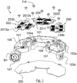
- the electronic assembly 10 for a rotating electrical machine is described with reference to Figures 1 to 10 .
- the rotating electrical machine is in a non-limiting example an alternator-starter.
- the rotating electrical machine is in this type of application used for the electrical generation and starting of the engine (with the so-called "Stop & Go" or "Stop / Start” feature in English).
- the overmolded case-piece 100 is illustrated on the figure 2 to 4 .
- the over-molded case-piece 100 is made of plastic material.
- the plastic material is PPS (Polyphenylene Sulfide), PBT (Polybutylene Terephthalate) or PPA (Polyphthalamides).
- plastics are inexpensive plastics whose temperature resistance is of the order of 120 ° C to 250 ° C. It is indeed not necessary to use a high-end plastic that withstands higher temperatures because there are no electrical welds or laser welds of the power modules 200 made at the molded-case part .
- the housings 101 are adapted to each receive a power module 200.
- the power conducting part 102 also called a power trace or a power bus, allows the current to pass through the components of the power modules 200. It is overmolded in said overmolded case-piece 100 as illustrated in FIGS. section 3 and 4. It comprises a plurality of overmolded outer power connection tongues 102 ', a power connection tab 102' being associated with a power module 200. Thus, a power connection tab 102 'opens into each housing 101 and is adapted to cooperate with a power connector (described below) of a power module 200.
- the tongues 102 ' are positioned parallel to the (horizontal) plane of the molded housing part 100; this makes it possible to reduce the vertical bulk of the electronic assembly 10.
- phase traces 103a, 103b are overmolded in said over-molded case-piece 100.
- Two phase traces 103a, 103b are associated with a power module 200. They make it possible to connect each power module 200 to the phases of the stator.
- two phase traces 103a, 103b are disposed in each housing 101 at right angles to the plane of said overmolded case-piece 100.
- Overmolding the phase traces 103a, 103b provides modularity as to the position of the phase outputs of the stator. It is easy to choose to overmould the traces at this or that place of the overmolded part-case according to the wishes of the electrical machine manufacturers for example and the number of phases of the machine.
- the mounting holes 104 ', 104a and 104b illustrated on the figures 2 and 4 are adapted to receive mounting means 114 for mounting each power module 200 on said molded case-piece 100.
- each housing 101 has three mounting holes 104 ', 104a and 104b, an orifice 104' being integrated in the power tab 102 'and an orifice 104a and 104b being integrated respectively in each phase tab 103a ', 103b'.
- the inner circumference of the overmolded casing member 100 is at the periphery of a location 108 for receiving the rotor shaft.
- the first and second mounting holes are adapted to receive mounting means such as in a non-limiting example fastening screws (not shown).
- these mounting means 105-106 of the over-molded housing part make it possible to mount the set of power modules 200 on the dissipator of the rotating electrical machine. There are no longer mounting means associated with each power module. This reduces the number mounting means which optimizes the volume occupied by the electronic assembly 10. These 105-106-screw mounting means make it easy to mount and dismount the molded housing part 10 of the rotating electrical machine without risk of deterioration. .
- the overmolded case-piece 100 furthermore comprises a signal bus (not illustrated) which connects in a conventional manner, in a nonlimiting example by wire bonding, to the signal components of the modules of FIG. power.
- the power modules are described below.
- a power module 200 is illustrated on the Figures 5 and 6 in non-limiting embodiments.
- the 2020 electronic power switches and the 2030 signal components are mounted on the 2010 conductive substrate.
- the electronic switches are in a nonlimiting example of the MOSFET transistors, the switches of a module being intended to provide at least one rectifier / inverter bridge arm for a phase of the rotating electrical machine.
- the power module 200 includes two MOSFETs for a bridge arm. It is therefore easy to adapt the electronic assembly 10 for a three-phase machine or a hexaphase machine.
- the power connectors 2011 and phase 2012a, 2012b include respective mounting holes 2014 ', 2014a, 2014b corresponding to the mounting holes 104', 104a, 104b of the overmolded case-piece 100, namely, the orifices 2014 ', 2014a, 2014b are adapted to be positioned respectively vis-à-vis the mounting holes 104 ', 104a, 104b.
- a power module 100 has 3 mounting holes 2014 ', 2014a, 2014b. They allow to receive the mounting means 114, which are in a non-limiting example of the fixing screws.
- the fixing screws 114 make it possible not only to carry out the mechanical strength of the power modules in the overmolded casing part 100 but also to perform together with the connectors 2011 and 2012a and 2012b respectively an electrical connection between the modules of power 200 and the power conducting part 102, and an electrical connection between the power modules 200 and the phase traces 103a, 103b.
- the 2011 and 2012a and 2012b power connectors are positioned parallel to the 2010 driver support plane, which allows to reduce the vertical bulk of the electronic assembly 10.
- a power module 200 can thus be easily mounted and dismounted from the overmolded casing member 100 via the fixing screws 114 which fit into the mounting holes 2014 ', 2014a, 2014b and 104', 104a, 104b. It is thus possible to disassemble one or more defective power modules without damaging the rest of the electronic assembly 10 or the rotating electrical machine.
- phase welds present in the state of the prior art have been replaced by mechanical means which fulfill an electrical connection function. By eliminating these phase welds, it reduces the overall size of the electronic assembly since it is no longer necessary to have specific access to said phases to achieve a weld.
- the conductive power support 2010 of the power module 200 consists of three power conductive traces separated by an insulating layer (epoxy) and hosting a PCB circuit ("Printed Circuit Board") for the components 2030 (English “driver”
- PCB circuit Printed Circuit Board
- the 2020 electronic switches are soldered directly to the visible parts of the 2040 power tracks.
- the lower ground plate 300 supports the overmolded casing part 100.
- the plate is in a non-limiting embodiment of aluminum and comprises an electrically insulating part (anodization for example) in order to ensure a good insulation with the conductive traces of power (leadframe) of potential B + and phases and a conductive portion for performing the ground connection of the power modules via a connection by brazed son ("wire bonding" in English) with the electronic power switches (MOSFET).
- the inner circumference of the plate 300 is at the periphery of a location 308 for receiving the rotor shaft.
- the third and fourth mounting holes 305 and 306 together with mounting screws (not shown) allow mounting of the overmolded housing member 100 on the bottom ground plate 300 and on the heatsink 11 of the rear bearing of the rotating electrical machine.
- all the mounting holes 105-106 and 305-306 are adapted to mount the electronic assembly 10 on the dissipator 11.
- the plate 300 is mounted directly on the dissipator 11. It is thus electrically connected to the general potential of the vehicle mass.
- the rotating electrical machine is an alternator-starter type machine operating under a DC voltage adapted to a vehicle with a 48-volt electrical network (or any other voltage), for example, Voltage potentials B + and B- are present in the machine and correspond respectively to +48 V and 0 V of 48 Volts. It will be noted here that the B- (0 V) and the general ground potential of the vehicle are electrically connected in the rotating electrical machine.
- the potential B + is connected to the electrical circuit of the vehicle through an electrical terminal 107 isolated from B-. As illustrated on figures 2 or 4 , the power conducting part 102 is connected to the electrical terminal 107. The conductive part 102 of the overmolded casing part 100 is thus connected to the potential B +. The power modules are thus connected to the potential B + via the power conducting part 102 (the power connectors 2011 seen previously being connected to the part 102 via the tabs 102 ').
- the potential B is conventionally connected to the negative electrical terminal of the battery or batteries of the vehicle while the general mass of the vehicle is connected to the chassis thereof on which is mounted the rear bearing 11 of the electric machine.
- the lower ground plate 300 is thus connected directly to the vehicle ground since mounted on the dissipator 11 of the rear bearing of said machine.
- the plate 300 thus makes it possible to ground the conductive support 2010 of the power modules 200 when the latter are mounted in the housings 101 of the overmolded housing part 100, each support 2010 then being in contact with the plate 300.
- the figure 8 illustrates in exploded assembly of the electronic assembly 10 on the dissipator 11 of the rear bearing of the rotating electrical machine.
- the dissipator 11 has first mounting orifices 115 which are opposite the third orifices 305 and first orifices 105 respectively of the lower ground plate 300 and the overmolded housing part 100, and second mounting orifices 116 which are found vis-à-vis the fourth orifices 306 and 1e nesss orifices 06 respectively of the lower ground plate 300 and the over-molded housing part 100.
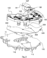
- the figure 9 and the figure 10 show the electronic assembly 10 assembled on the dissipator 11 of the rear bearing of the rotating electrical machine.
- the figure 10 illustrates further in a non-limiting embodiment an additional element 400 which comprises a control module.
- the control module comprises components for controlling the rotating electrical machine and in particular the adjustment of the machine by controlling the power modules via the signal bus.
- the control components being known to those skilled in the art, they are not described in detail in the following description.
- the control module is for example disposed above the casing-molded part on a plane parallel to said overmolded casing-piece.
- the present invention applies to all types of reversible polyphase rotating electrical machines, such as alternator-starters, driven for example by belt or integrated, and in particular for hybrid applications.
- the electronic assembly 10 may comprise as many power modules as necessary (two phases per module at most) to achieve a machine with three, five, six or seven phases.
- the power module 200 may comprise a ceramic comprising the control components (driver) of the electronic switches and the signal components.
- the electronic switches are transferred to the conductive support by soldering and wire bonding.
- the power module further comprises a contour of plastic material which allows the mechanical strength of all the elements of the power module between them.
- the plastic material of the contour is PEEK (polyetheretherketone) or PPA (polyphthalamide). These plastics are high-performance high performance plastics that can be used at high temperatures, for example around 350 ° C, which is interesting when soldering the electronic switches on the conductive support.
- a single housing is used, namely the overmolded housing part 100, in which the power modules without electrical and laser welds are mounted, the mounting on the dissipator of the electrical machine being carried out via mechanical mounting means common to all modules.
- a so-called “copper in lay” technology can be used for the power modules 200.
Landscapes
- Engineering & Computer Science (AREA)
- Power Engineering (AREA)
- Microelectronics & Electronic Packaging (AREA)
- Motor Or Generator Frames (AREA)
Claims (11)
- Elektronische Baugruppe (10) für eine elektrische Drehmaschine eines Kraftfahrzeugs, wobei die elektronische Baugruppe (10) umfasst:- ein aufgeformtes Gehäuseteil (100) aus Kunststoff, umfassend:dadurch gekennzeichnet, dass:- eine Vielzahl von Aufnahmen (101), die geeignet sind, jeweils ein Leistungsmodul (200) aufzunehmen;- ein leitendes Leistungsteil (102), das in dem aufgeformten Gehäuseteil (100) aufgeformt ist,- Montageöffnungen (104', 104a, 104b), die geeignet sind, Montagemittel (114) aufzunehmen, um jedes Leistungsmodul (200) auf dem aufgeformten Gehäuseteil (100) zu montieren;- das aufgeformte Gehäuseteil (100) eine Vielzahl von Phasen- und Massenspuren (103a, 103b, 102) umfasst;- die elektronische Baugruppe (10) ferner umfasst:- eine Vielzahl von Leistungsmodulen (200), umfassend:- einen leitenden Träger (2010), auf dem montiert sind:- eine Vielzahl von elektronischen Leistungsschaltern (2020);- Signalkomponenten (2030);wobei der leitende Träger (2010) umfasst:- einen Leistungsstecker (2011), der geeignet ist, an das leitende Leistungsteil (102) des aufgeformten Gehäuseteils (100) angeschlossen zu werden;- mindestens zwei Phasenstecker (2012a, 2012b), die geeignet sind, an die Phasenspuren (103a, 103b) des aufgeformten Gehäuseteils (100) angeschlossen zu werden;- eine untere Massenplatte (300), die geeignet ist, das aufgeformte Gehäuseteil (100) aufzunehmen und auf einem Wärmeableiter (11) der elektrischen Drehmaschine montiert zu werden.
- Elektronische Baugruppe (10) nach Anspruch 1, bei der der Kunststoff des aufgeformten Gehäuseteils (100) PPS oder PBT ist.
- Elektronische Baugruppe (10) nach Anspruch 1 oder Anspruch 2, bei der das leitende Leistungsteil (102) des aufgeformten Gehäuseteils (100) eine Vielzahl von Leistungsverbindungslaschen (102') umfasst, die parallel zur Ebene des aufgeformten Gehäuseteils (100) angeordnet sind, wobei die Leistungsverbindungslasche (102') geeignet ist, mit einem Leistungsmodul (200) zusammenzuwirken.
- Elektronische Baugruppe (10) nach einem der vorhergehenden Ansprüche 1 bis 3, bei der die Phasenspuren (103a, 103b) des aufgeformten Gehäuseteils (100) jeweils eine erste Phasenanschlusslasche (103a', 103b') umfassen, die geeignet ist, ein Leistungsmodul (200) anzuschließen, wobei eine erste Phasenanschlusslasche (103a', 103b') parallel zur Ebene des aufgeformten Gehäuseteils (100) angeordnet ist.
- Elektronische Baugruppe (10) nach einem der vorhergehenden Ansprüche 1 bis 4, bei der die Phasenspuren (103a, 103b) des aufgeformten Gehäuseteils (100) jeweils eine zweite Phasenanschlusslasche (103a", 103b") umfassen, die geeignet ist, eine Phase des Stators anzuschließen, wobei eine zweite Lasche (103a", 103b") vertikal zur Ebene des aufgeformten Gehäuseteils (100) angeordnet ist.
- Elektronische Baugruppe (10) nach einem der vorhergehenden Ansprüche 1 bis 5, bei der das aufgeformte Gehäuseteil (100) erste und zweite Montageöffnungen (105-106) umfasst, und die untere Massenplatte (300) dritte und vierte Montageöffnungen (305-306) umfasst, wobei die Montageöffnungen (105-106; 305-306) geeignet sind, die elektronische Baugruppe (10) auf einem Wärmeableiter (11) der elektrischen Drehmaschine zu montieren.
- Elektronische Baugruppe (10) nach einem der vorhergehenden Ansprüche 1 bis 6, bei der der leitende Träger (2010) eines Leistungsmoduls (200) eine gedruckte Leiterplatte PCB ist.
- Elektronische Baugruppe (10) nach einem der vorhergehenden Ansprüche 1 bis 7, bei der die Leistungs- (2011) und Phasenstecker (2012a, 2012b) eines Leistungsmoduls (200) jeweilige Montageöffnungen (2014', 2014a, 2014b) umfassen, die geeignet sind, gegenüber den Montageöffnungen (104', 104a, 104b) des aufgeformten Gehäuseteils (100) angeordnet zu sein und die Montagemittel (114) aufzunehmen.
- Elektronische Baugruppe (10) nach einem der vorhergehenden Ansprüche 1 bis 8, bei der die Leistungs- (2011) und Phasenstecker (2012a, 2012b) eines Leistungsmoduls parallel zur Ebene des leitenden Trägers (2010) angeordnet sind.
- Elektrische Drehmaschine, umfassend:- einen Rotor;- einen an den Rotor gekoppelten Stator, umfassend eine Vielzahl von Phasen;- eine elektronische Baugruppe (10) nach einem der vorhergehenden Ansprüche, wobei das aufgeformte Gehäuseteil (100) aus Kunststoff der elektronischen Baugruppe (10) geeignet ist, an die Phasen des Stators angeschlossen zu werden;- ein hinteres Lager, das den Stator trägt; und- einen Wärmeableiter (11), auf dem die elektronische Baugruppe (10) montiert ist.
- Elektrische Drehmaschine nach dem vorhergehenden Anspruch 10, wobei die elektrische Drehmaschine ein Startergenerator ist.
Applications Claiming Priority (2)
| Application Number | Priority Date | Filing Date | Title |
|---|---|---|---|
| FR1454039A FR3020726B1 (fr) | 2014-05-05 | 2014-05-05 | Ensemble electronique pour machine electrique tournante pour vehicule automobile |
| PCT/FR2015/051143 WO2015170035A1 (fr) | 2014-05-05 | 2015-04-28 | Ensemble électronique pour machine électrique tournante pour véhicule automobile |
Publications (2)
| Publication Number | Publication Date |
|---|---|
| EP3140901A1 EP3140901A1 (de) | 2017-03-15 |
| EP3140901B1 true EP3140901B1 (de) | 2018-03-14 |
Family
ID=51862371
Family Applications (1)
| Application Number | Title | Priority Date | Filing Date |
|---|---|---|---|
| EP15724339.5A Not-in-force EP3140901B1 (de) | 2014-05-05 | 2015-04-28 | Elektronische baugruppe für eine elektrische drehmaschine für ein kraftfahrzeug |
Country Status (6)
| Country | Link |
|---|---|
| US (1) | US10097068B2 (de) |
| EP (1) | EP3140901B1 (de) |
| CN (1) | CN106464089B (de) |
| ES (1) | ES2668375T3 (de) |
| FR (1) | FR3020726B1 (de) |
| WO (1) | WO2015170035A1 (de) |
Families Citing this family (11)
| Publication number | Priority date | Publication date | Assignee | Title |
|---|---|---|---|---|
| EP3297143B1 (de) * | 2015-05-15 | 2019-11-06 | Mitsubishi Electric Corporation | Wechselstromgenerator für ein fahrzeug |
| FR3044839B1 (fr) * | 2015-12-02 | 2022-12-30 | Valeo Systemes De Controle Moteur | Connecteur electrique destine a connecter un dispositif electrique avec une machine electrique commandee par ledit dispositif |
| FR3044838B1 (fr) * | 2015-12-02 | 2022-12-30 | Valeo Systemes De Controle Moteur | Connecteur electrique destine a etre connecte electriquement a une source d'energie electrique |
| FR3047851A1 (fr) * | 2016-02-15 | 2017-08-18 | Valeo Equip Electr Moteur | Ensemble electronique d'une machine electrique tournante |
| IT201700024276A1 (it) * | 2017-03-03 | 2018-09-03 | Spal Automotive Srl | Macchina elettrica |
| FR3069382B1 (fr) * | 2017-07-21 | 2022-07-29 | Valeo Equip Electr Moteur | Procede de montage d'un module electrique sur un support electriquement conducteur et dispositifs electriques correspondants |
| DE102017131326A1 (de) | 2017-12-27 | 2019-06-27 | Beckhoff Automation Gmbh | Statormodul |
| FR3105890B1 (fr) * | 2019-12-27 | 2021-11-26 | Valeo Equip Electr Moteur | Module electronique pour machine electrique tournante |
| FR3105889B1 (fr) * | 2019-12-27 | 2022-01-07 | Valeo Equip Electr Moteur | Module electronique pour machine electrique tournante |
| CN116207926A (zh) * | 2021-11-30 | 2023-06-02 | 日本电产(大连)有限公司 | 马达 |
| CN118630988A (zh) | 2023-03-07 | 2024-09-10 | 台达电子工业股份有限公司 | 电动马达 |
Family Cites Families (10)
| Publication number | Priority date | Publication date | Assignee | Title |
|---|---|---|---|---|
| US5093592A (en) * | 1987-04-03 | 1992-03-03 | General Electric Company | Dynamoelectric machine with a terminal board mounted thereto |
| JP2002519986A (ja) * | 1998-06-30 | 2002-07-02 | ゼネラル・エレクトリック・カンパニイ | 電子転流式電動機用の電動機端蓋集成体 |
| US6225716B1 (en) * | 1998-12-15 | 2001-05-01 | Honeywell International Inc | Commutator assembly apparatus for hall sensor devices |
| JP2005117708A (ja) * | 2003-10-02 | 2005-04-28 | Denso Corp | 制御手段一体型交流モータ |
| FR2886476B1 (fr) * | 2005-05-31 | 2007-07-06 | Valeo Equip Electr Moteur | Piece d'interconnexion de puissance pour machine electrique tournante |
| FR2886506B1 (fr) * | 2005-05-31 | 2011-02-25 | Valeo Equip Electr Moteur | Module electronique pour machine electrique tournante |
| FR2886505B1 (fr) * | 2005-05-31 | 2007-07-06 | Valeo Equip Electr Moteur | Assemblage de composants electroniques pour machine electrique tournante |
| FR2936913B1 (fr) * | 2008-10-02 | 2010-11-05 | Valeo Equip Electr Moteur | Ensemble regulateur de tension porte balais pour machine electrique tournante et machine electrique tournante comportant un tel ensemble. |
| FR2967846B1 (fr) * | 2010-11-23 | 2012-11-30 | Valeo Equip Electr Moteur | Procede d'interconnexion de modules electroniques de puissance d'une machine electrique tournante et assemblage de modules de puissance interconnectes obtenu par ce procede |
| FR2967845B1 (fr) | 2010-11-23 | 2013-08-02 | Valeo Equip Electr Moteur | Architecture de modules electroniques de puissance interconnectes pour une machine electrique tournante et machine electrique tournante comprenant une telle architecture |
-
2014
- 2014-05-05 FR FR1454039A patent/FR3020726B1/fr not_active Expired - Fee Related
-
2015
- 2015-04-28 US US15/308,854 patent/US10097068B2/en not_active Expired - Fee Related
- 2015-04-28 WO PCT/FR2015/051143 patent/WO2015170035A1/fr not_active Ceased
- 2015-04-28 EP EP15724339.5A patent/EP3140901B1/de not_active Not-in-force
- 2015-04-28 CN CN201580023197.3A patent/CN106464089B/zh not_active Expired - Fee Related
- 2015-04-28 ES ES15724339.5T patent/ES2668375T3/es active Active
Also Published As
| Publication number | Publication date |
|---|---|
| US10097068B2 (en) | 2018-10-09 |
| CN106464089A (zh) | 2017-02-22 |
| WO2015170035A1 (fr) | 2015-11-12 |
| CN106464089B (zh) | 2019-09-13 |
| FR3020726A1 (fr) | 2015-11-06 |
| EP3140901A1 (de) | 2017-03-15 |
| US20170077788A1 (en) | 2017-03-16 |
| FR3020726B1 (fr) | 2016-04-15 |
| ES2668375T3 (es) | 2018-05-17 |
Similar Documents
| Publication | Publication Date | Title |
|---|---|---|
| EP3140901B1 (de) | Elektronische baugruppe für eine elektrische drehmaschine für ein kraftfahrzeug | |
| WO2015170036A1 (fr) | Module de puissance d'un ensemble electronique pour machine electrique tournante pour vehicule automobile | |
| EP1523803B1 (de) | Steuer- und leistungsmodul einer integrierten anlasser-lichtmaschine | |
| EP1886401B1 (de) | Elektronikmodul für eine elektrische drehmaschine | |
| EP1886396B1 (de) | Rotierende elektrische Maschine mit ein Leistungsverbindungsstück | |
| EP1886397B1 (de) | Kühler für elektronische komponente einer elektrischen rotationsmaschine | |
| EP1886395A1 (de) | Signalverbindungsteil für eine elektrische drehmaschine | |
| EP1886400B1 (de) | Anordnung elektronischer bauteile für eine elektrische rotationsmaschine | |
| FR2930380A1 (fr) | Dispositif formant moteur electrique pour direction assistee et dispositif de direction assistee | |
| EP2643921A1 (de) | Architektur von miteinander verbundenen elektronischen leistungsmodulen für eine elektrische drehmaschine und elektrische drehmaschine mit einer solchen architektur | |
| FR2946475A1 (fr) | Machine dynamoelectrique automobile | |
| FR3069116A1 (fr) | Machine electrique tournante munie d'un capteur de temperature | |
| EP3718197A1 (de) | Elektrischer phasenverbinder für einen stator einer elektrischen drehmaschine | |
| EP2965407A2 (de) | Elektronisches leistungsmodul, verfahren zur herstellung solch eines moduls und elektrische drehmaschine eines kraftfahrzeugs damit | |
| WO2015170037A1 (fr) | Piece-boîtier surmoulee d'un ensemble electronique pour machine electrique tournante pour vehicule automobile | |
| FR3014257A1 (fr) | Module electronique de puissance, procede de fabrication d'un tel module et machine electrique tournante polyphasee de vehicule automobile le comprenant | |
| FR3047851A1 (fr) | Ensemble electronique d'une machine electrique tournante | |
| FR3026904A1 (fr) | Machine electrique tournante munie d'un module capacitif | |
| FR3072461A1 (fr) | Capteur pour la mesure d'un courant de sortie d'un systeme electrique | |
| FR3018011A1 (fr) | Ensemble electronique pour machine electrique tournante pour vehicule automobile | |
| FR3015801A1 (fr) | Machine electrique tournante pour vehicules | |
| FR3029030A1 (fr) | Module electronique de puissance, convertisseur bitensions et machine electrique tournante polyphasee bitensions de vehicule automobile | |
| FR3050864A1 (fr) | Module electronique de puissance, ensemble electrique et compresseur de suralimentation electrique comprenant un tel module electronique de puissance | |
| FR3048828A1 (fr) | Machine electrique tournante munie d'un capteur de mesure de champ magnetique pour la mesure d'un courant |
Legal Events
| Date | Code | Title | Description |
|---|---|---|---|
| PUAI | Public reference made under article 153(3) epc to a published international application that has entered the european phase |
Free format text: ORIGINAL CODE: 0009012 |
|
| 17P | Request for examination filed |
Effective date: 20161110 |
|
| AK | Designated contracting states |
Kind code of ref document: A1 Designated state(s): AL AT BE BG CH CY CZ DE DK EE ES FI FR GB GR HR HU IE IS IT LI LT LU LV MC MK MT NL NO PL PT RO RS SE SI SK SM TR |
|
| AX | Request for extension of the european patent |
Extension state: BA ME |
|
| DAV | Request for validation of the european patent (deleted) | ||
| DAX | Request for extension of the european patent (deleted) | ||
| GRAP | Despatch of communication of intention to grant a patent |
Free format text: ORIGINAL CODE: EPIDOSNIGR1 |
|
| INTG | Intention to grant announced |
Effective date: 20171002 |
|
| GRAS | Grant fee paid |
Free format text: ORIGINAL CODE: EPIDOSNIGR3 |
|
| GRAA | (expected) grant |
Free format text: ORIGINAL CODE: 0009210 |
|
| AK | Designated contracting states |
Kind code of ref document: B1 Designated state(s): AL AT BE BG CH CY CZ DE DK EE ES FI FR GB GR HR HU IE IS IT LI LT LU LV MC MK MT NL NO PL PT RO RS SE SI SK SM TR |
|
| REG | Reference to a national code |
Ref country code: GB Ref legal event code: FG4D Free format text: NOT ENGLISH |
|
| REG | Reference to a national code |
Ref country code: CH Ref legal event code: EP Ref country code: AT Ref legal event code: REF Ref document number: 979765 Country of ref document: AT Kind code of ref document: T Effective date: 20180315 |
|
| REG | Reference to a national code |
Ref country code: IE Ref legal event code: FG4D Free format text: LANGUAGE OF EP DOCUMENT: FRENCH |
|
| REG | Reference to a national code |
Ref country code: DE Ref legal event code: R096 Ref document number: 602015008866 Country of ref document: DE |
|
| REG | Reference to a national code |
Ref country code: FR Ref legal event code: PLFP Year of fee payment: 4 |
|
| REG | Reference to a national code |
Ref country code: ES Ref legal event code: FG2A Ref document number: 2668375 Country of ref document: ES Kind code of ref document: T3 Effective date: 20180517 |
|
| REG | Reference to a national code |
Ref country code: NL Ref legal event code: MP Effective date: 20180314 |
|
| REG | Reference to a national code |
Ref country code: LT Ref legal event code: MG4D |
|
| PG25 | Lapsed in a contracting state [announced via postgrant information from national office to epo] |
Ref country code: FI Free format text: LAPSE BECAUSE OF FAILURE TO SUBMIT A TRANSLATION OF THE DESCRIPTION OR TO PAY THE FEE WITHIN THE PRESCRIBED TIME-LIMIT Effective date: 20180314 Ref country code: NO Free format text: LAPSE BECAUSE OF FAILURE TO SUBMIT A TRANSLATION OF THE DESCRIPTION OR TO PAY THE FEE WITHIN THE PRESCRIBED TIME-LIMIT Effective date: 20180614 Ref country code: LT Free format text: LAPSE BECAUSE OF FAILURE TO SUBMIT A TRANSLATION OF THE DESCRIPTION OR TO PAY THE FEE WITHIN THE PRESCRIBED TIME-LIMIT Effective date: 20180314 Ref country code: HR Free format text: LAPSE BECAUSE OF FAILURE TO SUBMIT A TRANSLATION OF THE DESCRIPTION OR TO PAY THE FEE WITHIN THE PRESCRIBED TIME-LIMIT Effective date: 20180314 Ref country code: CY Free format text: LAPSE BECAUSE OF FAILURE TO SUBMIT A TRANSLATION OF THE DESCRIPTION OR TO PAY THE FEE WITHIN THE PRESCRIBED TIME-LIMIT Effective date: 20180314 |
|
| REG | Reference to a national code |
Ref country code: AT Ref legal event code: MK05 Ref document number: 979765 Country of ref document: AT Kind code of ref document: T Effective date: 20180314 |
|
| PG25 | Lapsed in a contracting state [announced via postgrant information from national office to epo] |
Ref country code: GR Free format text: LAPSE BECAUSE OF FAILURE TO SUBMIT A TRANSLATION OF THE DESCRIPTION OR TO PAY THE FEE WITHIN THE PRESCRIBED TIME-LIMIT Effective date: 20180615 Ref country code: LV Free format text: LAPSE BECAUSE OF FAILURE TO SUBMIT A TRANSLATION OF THE DESCRIPTION OR TO PAY THE FEE WITHIN THE PRESCRIBED TIME-LIMIT Effective date: 20180314 Ref country code: SE Free format text: LAPSE BECAUSE OF FAILURE TO SUBMIT A TRANSLATION OF THE DESCRIPTION OR TO PAY THE FEE WITHIN THE PRESCRIBED TIME-LIMIT Effective date: 20180314 Ref country code: RS Free format text: LAPSE BECAUSE OF FAILURE TO SUBMIT A TRANSLATION OF THE DESCRIPTION OR TO PAY THE FEE WITHIN THE PRESCRIBED TIME-LIMIT Effective date: 20180314 Ref country code: BG Free format text: LAPSE BECAUSE OF FAILURE TO SUBMIT A TRANSLATION OF THE DESCRIPTION OR TO PAY THE FEE WITHIN THE PRESCRIBED TIME-LIMIT Effective date: 20180614 |
|
| PG25 | Lapsed in a contracting state [announced via postgrant information from national office to epo] |
Ref country code: MT Free format text: LAPSE BECAUSE OF FAILURE TO SUBMIT A TRANSLATION OF THE DESCRIPTION OR TO PAY THE FEE WITHIN THE PRESCRIBED TIME-LIMIT Effective date: 20180314 |
|
| PG25 | Lapsed in a contracting state [announced via postgrant information from national office to epo] |
Ref country code: NL Free format text: LAPSE BECAUSE OF FAILURE TO SUBMIT A TRANSLATION OF THE DESCRIPTION OR TO PAY THE FEE WITHIN THE PRESCRIBED TIME-LIMIT Effective date: 20180314 Ref country code: EE Free format text: LAPSE BECAUSE OF FAILURE TO SUBMIT A TRANSLATION OF THE DESCRIPTION OR TO PAY THE FEE WITHIN THE PRESCRIBED TIME-LIMIT Effective date: 20180314 Ref country code: PL Free format text: LAPSE BECAUSE OF FAILURE TO SUBMIT A TRANSLATION OF THE DESCRIPTION OR TO PAY THE FEE WITHIN THE PRESCRIBED TIME-LIMIT Effective date: 20180314 Ref country code: AL Free format text: LAPSE BECAUSE OF FAILURE TO SUBMIT A TRANSLATION OF THE DESCRIPTION OR TO PAY THE FEE WITHIN THE PRESCRIBED TIME-LIMIT Effective date: 20180314 Ref country code: RO Free format text: LAPSE BECAUSE OF FAILURE TO SUBMIT A TRANSLATION OF THE DESCRIPTION OR TO PAY THE FEE WITHIN THE PRESCRIBED TIME-LIMIT Effective date: 20180314 |
|
| PG25 | Lapsed in a contracting state [announced via postgrant information from national office to epo] |
Ref country code: AT Free format text: LAPSE BECAUSE OF FAILURE TO SUBMIT A TRANSLATION OF THE DESCRIPTION OR TO PAY THE FEE WITHIN THE PRESCRIBED TIME-LIMIT Effective date: 20180314 Ref country code: SM Free format text: LAPSE BECAUSE OF FAILURE TO SUBMIT A TRANSLATION OF THE DESCRIPTION OR TO PAY THE FEE WITHIN THE PRESCRIBED TIME-LIMIT Effective date: 20180314 Ref country code: SK Free format text: LAPSE BECAUSE OF FAILURE TO SUBMIT A TRANSLATION OF THE DESCRIPTION OR TO PAY THE FEE WITHIN THE PRESCRIBED TIME-LIMIT Effective date: 20180314 |
|
| REG | Reference to a national code |
Ref country code: CH Ref legal event code: PL |
|
| REG | Reference to a national code |
Ref country code: DE Ref legal event code: R097 Ref document number: 602015008866 Country of ref document: DE |
|
| REG | Reference to a national code |
Ref country code: BE Ref legal event code: MM Effective date: 20180430 |
|
| PG25 | Lapsed in a contracting state [announced via postgrant information from national office to epo] |
Ref country code: PT Free format text: LAPSE BECAUSE OF FAILURE TO SUBMIT A TRANSLATION OF THE DESCRIPTION OR TO PAY THE FEE WITHIN THE PRESCRIBED TIME-LIMIT Effective date: 20180716 |
|
| PLBE | No opposition filed within time limit |
Free format text: ORIGINAL CODE: 0009261 |
|
| STAA | Information on the status of an ep patent application or granted ep patent |
Free format text: STATUS: NO OPPOSITION FILED WITHIN TIME LIMIT |
|
| REG | Reference to a national code |
Ref country code: IE Ref legal event code: MM4A |
|
| PG25 | Lapsed in a contracting state [announced via postgrant information from national office to epo] |
Ref country code: MC Free format text: LAPSE BECAUSE OF FAILURE TO SUBMIT A TRANSLATION OF THE DESCRIPTION OR TO PAY THE FEE WITHIN THE PRESCRIBED TIME-LIMIT Effective date: 20180314 Ref country code: LU Free format text: LAPSE BECAUSE OF NON-PAYMENT OF DUE FEES Effective date: 20180428 Ref country code: DK Free format text: LAPSE BECAUSE OF FAILURE TO SUBMIT A TRANSLATION OF THE DESCRIPTION OR TO PAY THE FEE WITHIN THE PRESCRIBED TIME-LIMIT Effective date: 20180314 |
|
| 26N | No opposition filed |
Effective date: 20181217 |
|
| PG25 | Lapsed in a contracting state [announced via postgrant information from national office to epo] |
Ref country code: CH Free format text: LAPSE BECAUSE OF NON-PAYMENT OF DUE FEES Effective date: 20180430 Ref country code: LI Free format text: LAPSE BECAUSE OF NON-PAYMENT OF DUE FEES Effective date: 20180430 Ref country code: BE Free format text: LAPSE BECAUSE OF NON-PAYMENT OF DUE FEES Effective date: 20180430 Ref country code: SI Free format text: LAPSE BECAUSE OF FAILURE TO SUBMIT A TRANSLATION OF THE DESCRIPTION OR TO PAY THE FEE WITHIN THE PRESCRIBED TIME-LIMIT Effective date: 20180314 |
|
| PG25 | Lapsed in a contracting state [announced via postgrant information from national office to epo] |
Ref country code: IE Free format text: LAPSE BECAUSE OF NON-PAYMENT OF DUE FEES Effective date: 20180428 |
|
| PG25 | Lapsed in a contracting state [announced via postgrant information from national office to epo] |
Ref country code: TR Free format text: LAPSE BECAUSE OF FAILURE TO SUBMIT A TRANSLATION OF THE DESCRIPTION OR TO PAY THE FEE WITHIN THE PRESCRIBED TIME-LIMIT Effective date: 20180314 |
|
| PG25 | Lapsed in a contracting state [announced via postgrant information from national office to epo] |
Ref country code: HU Free format text: LAPSE BECAUSE OF FAILURE TO SUBMIT A TRANSLATION OF THE DESCRIPTION OR TO PAY THE FEE WITHIN THE PRESCRIBED TIME-LIMIT; INVALID AB INITIO Effective date: 20150428 Ref country code: MK Free format text: LAPSE BECAUSE OF NON-PAYMENT OF DUE FEES Effective date: 20180314 |
|
| PG25 | Lapsed in a contracting state [announced via postgrant information from national office to epo] |
Ref country code: IS Free format text: LAPSE BECAUSE OF FAILURE TO SUBMIT A TRANSLATION OF THE DESCRIPTION OR TO PAY THE FEE WITHIN THE PRESCRIBED TIME-LIMIT Effective date: 20180714 |
|
| PGFP | Annual fee paid to national office [announced via postgrant information from national office to epo] |
Ref country code: CZ Payment date: 20220322 Year of fee payment: 8 |
|
| PGFP | Annual fee paid to national office [announced via postgrant information from national office to epo] |
Ref country code: IT Payment date: 20220411 Year of fee payment: 8 Ref country code: GB Payment date: 20220421 Year of fee payment: 8 Ref country code: FR Payment date: 20220428 Year of fee payment: 8 Ref country code: ES Payment date: 20220503 Year of fee payment: 8 Ref country code: DE Payment date: 20220406 Year of fee payment: 8 |
|
| P01 | Opt-out of the competence of the unified patent court (upc) registered |
Effective date: 20230528 |
|
| REG | Reference to a national code |
Ref country code: DE Ref legal event code: R119 Ref document number: 602015008866 Country of ref document: DE |
|
| GBPC | Gb: european patent ceased through non-payment of renewal fee |
Effective date: 20230428 |
|
| PG25 | Lapsed in a contracting state [announced via postgrant information from national office to epo] |
Ref country code: GB Free format text: LAPSE BECAUSE OF NON-PAYMENT OF DUE FEES Effective date: 20230428 |
|
| PG25 | Lapsed in a contracting state [announced via postgrant information from national office to epo] |
Ref country code: GB Free format text: LAPSE BECAUSE OF NON-PAYMENT OF DUE FEES Effective date: 20230428 Ref country code: FR Free format text: LAPSE BECAUSE OF NON-PAYMENT OF DUE FEES Effective date: 20230430 Ref country code: DE Free format text: LAPSE BECAUSE OF NON-PAYMENT OF DUE FEES Effective date: 20231103 Ref country code: CZ Free format text: LAPSE BECAUSE OF NON-PAYMENT OF DUE FEES Effective date: 20230428 |
|
| PG25 | Lapsed in a contracting state [announced via postgrant information from national office to epo] |
Ref country code: IT Free format text: LAPSE BECAUSE OF NON-PAYMENT OF DUE FEES Effective date: 20230428 |
|
| REG | Reference to a national code |
Ref country code: ES Ref legal event code: FD2A Effective date: 20240605 |
|
| PG25 | Lapsed in a contracting state [announced via postgrant information from national office to epo] |
Ref country code: ES Free format text: LAPSE BECAUSE OF NON-PAYMENT OF DUE FEES Effective date: 20230429 |
|
| PG25 | Lapsed in a contracting state [announced via postgrant information from national office to epo] |
Ref country code: ES Free format text: LAPSE BECAUSE OF NON-PAYMENT OF DUE FEES Effective date: 20230429 |