EP3140908B1 - Verstärkerschaltung und verfahren - Google Patents
Verstärkerschaltung und verfahren Download PDFInfo
- Publication number
- EP3140908B1 EP3140908B1 EP14727643.0A EP14727643A EP3140908B1 EP 3140908 B1 EP3140908 B1 EP 3140908B1 EP 14727643 A EP14727643 A EP 14727643A EP 3140908 B1 EP3140908 B1 EP 3140908B1
- Authority
- EP
- European Patent Office
- Prior art keywords
- amplifier
- auxiliary
- transmission line
- length
- portions
- Prior art date
- Legal status (The legal status is an assumption and is not a legal conclusion. Google has not performed a legal analysis and makes no representation as to the accuracy of the status listed.)
- Active
Links
Images





Classifications
-
- H—ELECTRICITY
- H03—ELECTRONIC CIRCUITRY
- H03F—AMPLIFIERS
- H03F1/00—Details of amplifiers with only discharge tubes, only semiconductor devices or only unspecified devices as amplifying elements
- H03F1/02—Modifications of amplifiers to raise the efficiency, e.g. gliding Class A stages, use of an auxiliary oscillation
- H03F1/0205—Modifications of amplifiers to raise the efficiency, e.g. gliding Class A stages, use of an auxiliary oscillation in transistor amplifiers
- H03F1/0288—Modifications of amplifiers to raise the efficiency, e.g. gliding Class A stages, use of an auxiliary oscillation in transistor amplifiers using a main and one or several auxiliary peaking amplifiers whereby the load is connected to the main amplifier using an impedance inverter, e.g. Doherty amplifiers
-
- H—ELECTRICITY
- H03—ELECTRONIC CIRCUITRY
- H03F—AMPLIFIERS
- H03F3/00—Amplifiers with only discharge tubes or only semiconductor devices as amplifying elements
- H03F3/60—Amplifiers in which coupling networks have distributed constants, e.g. with waveguide resonators
- H03F3/602—Combinations of several amplifiers
-
- H—ELECTRICITY
- H03—ELECTRONIC CIRCUITRY
- H03F—AMPLIFIERS
- H03F3/00—Amplifiers with only discharge tubes or only semiconductor devices as amplifying elements
- H03F3/189—High-frequency amplifiers, e.g. radio frequency amplifiers
- H03F3/19—High-frequency amplifiers, e.g. radio frequency amplifiers with semiconductor devices only
-
- H—ELECTRICITY
- H03—ELECTRONIC CIRCUITRY
- H03F—AMPLIFIERS
- H03F2200/00—Indexing scheme relating to amplifiers
- H03F2200/423—Amplifier output adaptation especially for transmission line coupling purposes, e.g. impedance adaptation
-
- H—ELECTRICITY
- H03—ELECTRONIC CIRCUITRY
- H03F—AMPLIFIERS
- H03F2200/00—Indexing scheme relating to amplifiers
- H03F2200/451—Indexing scheme relating to amplifiers the amplifier being a radio frequency amplifier
-
- H—ELECTRICITY
- H03—ELECTRONIC CIRCUITRY
- H03F—AMPLIFIERS
- H03F3/00—Amplifiers with only discharge tubes or only semiconductor devices as amplifying elements
- H03F3/68—Combinations of amplifiers, e.g. multi-channel amplifiers for stereophonics
Definitions
- the present invention relates to an amplifier circuit and method, and more particularly to an amplifier circuit and method which provides improved efficiency, for example an amplifier circuit comprising at least first and second amplifiers configured to operate in Chireix and Doherty modes of operation.
- power amplifiers are often used to amplify wideband signals or signal combinations with high peak to average power ratio (PAR or PAPR).
- the amplifiers must then be able to repeatedly output very high power for very short periods, even though the bulk of the output power is generated at the much lower average power level.
- the amplitude of the signal follows a Rayleigh distribution.
- a conventional single-transistor power amplifier (for example a class B, AB or F power amplifier) has a fixed radio frequency (RF) load resistance and a fixed voltage supply.
- the bias in class B or AB amplifiers causes the output current to have a form close to that of a pulse train of half wave rectified sinusoid current pulses.
- the direct current (DC) current (and hence DC power) is therefore largely proportional to the RF output current amplitude (and voltage).
- the output power is proportional to the RF output current squared.
- the efficiency i.e. output power divided by DC power, is therefore also proportional to the output amplitude.
- the average efficiency of a power amplifier is consequently low when amplifying signals that on average have a low output amplitude (or power) compared to the maximum required output amplitude (or power), i.e. high PAR.
- a Chireix amplifier (as described in " High power outphasing modulation,” Proc. IRE, vol. 23, no. 11, pp. 1370-1392, Nov. 1935, by H Chireix ), or a Doherty amplifier (as described in " A new high efficiency power amplifier for modulated waves", by W. H. Doherty, Proc. IRE, vol. 24, no. 9, pp. 1163-1182, Sept. 1936 ) were the first examples of amplifiers based on multiple transistors with passive output network interaction and combination.
- the RF output current from the "peaking" sub-amplifier in the Doherty amplifier needs to rise linearly from zero at a "transition point” to full current at full amplitude.
- the "main” sub-amplifier has an entirely linear output current.
- the sum of the amplitudes of these currents deviates far from the ideal parabolic shape (of a constant efficiency amplifier), so the dip in efficiency in the upper amplitude region is quite substantial.
- Another way to intuitively get to the same result is to observe that the RF voltage at the peaking sub-amplifier is only medium high at the transition point, so the output current pulses will here experience large voltage drop across the transistor.
- the Chireix amplifier has high efficiency in the upper amplitude region, since both sub-amplifier RF voltage amplitudes are high, and close in phase with the respective RF currents. Since variations in output amplitude are accompanied by phase shifts in the sub-amplifier RF voltages this operation mode is called "outphasing". In the outphasing region, the current pulses experience low voltage drop across the transistors. The RF current increase at the transition point is very gradual, and the overall shape of the sum of RF current amplitudes is much closer to the ideal parabolic shape than for the Doherty amplifier.
- the drawback of having both RF voltages high is that the efficiency of the amplifier is degraded by shunt loss, i.e. loss that behaves like a resistor coupled from the transistor output to ground (RF wise). With low loss transistors, Chireix outphasing is very efficient.
- the first Chireix-Doherty amplifiers of WO 2004/057755 and also the improved variant of co-pending application PCT/SE2013/050605 have a Chireix pair that is outphasing with very high efficiency in a middle amplitude region.
- the upper amplitude region (its proportion determined by the size of the "peaking" sub-amplifier) they behave like the upper region in a Doherty amplifier, and are therefore sub-optimal when low shunt loss transistors are employed.
- the amplifiers in WO 2010/074615 increase the proportion of outphasing behavior, and exist in both 3-stage and 4-stage versions, but require different size sub-amplifiers and have slightly sub-optimal efficiency with very low-loss transistors.
- the 4-stage amplifiers Perreault are very close to optimal with very low-loss transistors, but do not exist for circuits having 3 sub-amplifier stages.
- the optimality also breaks down substantially if different size sub-amplifier pairs are employed.
- the amplifiers in WO 2013/087232 exist in 3-stage versions with equal size sub-amplifiers, but have sub-optimal efficiency in a middle amplitude region when the lowermost transition point is placed at too low an amplitude.
- an amplifier circuit comprising a first amplifier configured to amplify a first input signal. An output of the first amplifier is coupled to an output node via a first transmission line.
- the first transmission line comprises a first portion having a first characteristic impedance and a first length, and a second portion having a second characteristic impedance and a second length.
- the amplifier circuit further comprises a second amplifier configured to amplify a second input signal. An output of the second amplifier is coupled to the output node via a second transmission line.
- the second transmission line comprises a first portion having a first characteristic impedance and a first length, and a second portion having a second characteristic impedance and a second length.
- the amplifier circuit further comprises an auxiliary amplifier configured to amplify a third input signal.
- An output of the auxiliary amplifier is coupled via an auxiliary transmission line network to a first intersection between the first and second portions of the first transmission line, and to a second intersection between the first and second portions of the second transmission line.
- the first and second portions consist of a higher-impedance portion and a lower-impedance portion whose combined length is a half wavelength, wherein the lengths of the respective first portions of the first and second transmission lines sum to half a wavelength, and the lengths of the respective second portions of the first and second transmission lines sum to half a wavelength.
- a method in an amplifier circuit comprises the steps of amplifying a first input signal using a first amplifier, and coupling the amplified first input signal to an output node via a first transmission line, the first transmission line comprising a first portion having a first characteristic impedance and a first length, and a second portion having a second characteristic impedance and a second length.
- the method further comprises the steps of amplifying a second input signal using a second amplifier, and coupling the amplified second input signal to the output node via a second transmission line, the second transmission line comprising a first portion having a first characteristic impedance and a first length, and a second portion having a second characteristic impedance and a second length.
- the method further comprises the steps of amplifying a third input signal using an auxiliary amplifier, and coupling the output of the auxiliary amplifier via an auxiliary transmission line network to a first intersection between the first and second portions of the first transmission line, and to a second intersection between the first and second portions of the second transmission line, wherein for each of the first and second transmission lines, the first and second portions consist of a higher-impedance portion and a lower-impedance portion whose combined length is a half wavelength, and wherein the lengths of the respective first portions of the first and second transmission lines sum to half a wavelength, and the lengths of the respective second portions of the first and second transmission lines sum to half a wavelength.
- Embodiments of the present invention are aimed at providing 3-stage amplifiers with close to optimal efficiency for very low loss transistors.
- Other embodiments of the present invention are aimed at providing close to optimal 4-stage amplifiers with good efficiency also when different size sub-amplifier pairs are employed.
- the embodiments of the present invention aim to minimize series losses, including loss due to voltage drop across the transistor during the current pulse.
- Embodiments of the present invention achieve this by having small phase difference between RF currents and voltages at the respective sub-amplifiers' output nodes, and having high RF voltage swing when current is drawn.
- Beneficial interactions between sub-amplifiers that enable this behaviour are in the embodiments of the present invention made possible by new structures of the electrical network over which the sub-amplifiers are interacting and connected to the output.
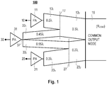
- Figure 1 shows an amplifier circuit according to an embodiment of the invention.
- the amplifier circuit comprises a first amplifier 11 configured to amplify a first input signal 10.
- An output of the first amplifier 11 is coupled to an output node 15 via a first transmission line 13.
- the first transmission line 13 comprises a first portion 13 1 having a first characteristic impedance and a first length, and a second portion 13 2 having a second characteristic impedance and a second length.
- the amplifier circuit also comprises a second amplifier 21 configured to amplify a second input signal 20.
- An output of the second amplifier 21 is coupled to the output node 15 via a second transmission line 23.
- the second transmission line 23 comprises a first portion 23 1 having a first characteristic impedance and a first length, and a second portion 23 2 having a second characteristic impedance and a second length.
- the amplifier circuit also comprises an auxiliary amplifier 31 (also referred to herein as a peaking amplifier) configured to amplify a third input signal 30.
- An output of the auxiliary amplifier 31 is coupled via an auxiliary transmission line network (33 1 , 33 2 ) to a first intersection 17 between the first and second portions 13 1 , 13 2 of the first transmission line 13, and to a second intersection 27 between the first and second portions 23 1 , 23 2 of the second transmission line 23.
- the first and second portions consist of a higher-impedance portion and a lower-impedance portion whose combined length is a half wavelength.
- the first transmission line 13 comprises a first portion 13 1 having an electrical length of 0.2 ⁇ , and a second portion 13 2 having an electrical length of 0.3 ⁇ , such that the sum of the electrical lengths is 0.5 ⁇ .
- the characteristic impedance of the first portion 13 1 is higher that the characteristic impedance of the second portion 13 2 , as represented by the relative thicknesses of the transmission lines (the smaller the thickness the higher the characteristic impedance, and vice versa, which also applies to other embodiments of the invention as described herein).
- the lengths of the respective first portions 13 1 , 23 1 of the first and second transmission lines 13, 23 also sum to half a wavelength
- the lengths of the respective second portions 13 2 , 23 2 of the first and second transmission lines 13, 23 also sum to half a wavelength
- the lengths of the respective first portions 13 1 , 23 1 of the first and second transmission lines 13, 23, i.e. 0.2 ⁇ and of 0.3 ⁇ , respectively, sum to half a wavelength
- the lengths of the respective second portions 13 2 , 23 2 of the first and second transmission lines 13, 23 also sum to half a wavelength, i.e. the sum of 0.3 ⁇ and 0.2 ⁇ .
- the length of the first portion 13 1 of the first transmission line 13 is substantially equal to the length of the second portion 23 2 of the second transmission line 23 and/or wherein the length of the first portion 23 1 of the second transmission line 23 is substantially equal to the length of the second portion 13 2 of the first transmission line 13.
- the auxiliary amplifier 31 is coupled directly (or by a half wavelength line) to a auxiliary junction 37 from which it branches (via first and second auxiliary transmission lines 33 1 and 33 2 ) to the Chireix pair midpoint junctions (i.e. the first and second intersections 17, 27).
- the length of each of the first and second auxiliary transmission lines 33 1 and 33 2 is three quarters of a wavelength minus the length of the second portion of the respective transmission lines which connects the auxiliary transmission line to the output (i.e. the section of transmission line from the midpoint to the output).
- the total length from the auxiliary amplifier 31 to the output 15 through any path is equal to three quarter wavelengths (assuming the auxiliary amplifier 31 is directly coupled to the auxiliary junction 37).
- these new amplifiers extend the Chireix outphasing operation from low amplitude the whole way to the maximum amplitude into a wide and very efficient region.
- a feature of the output network in the example of Figure 1 is the branching structure that connects a single sub-amplifier (or a Chireix pair in the 4-stage case) to points along the lines that connect two other amplifiers to the output.
- a feature of the output network in the example of Figure 1 is the branching structure that connects a single sub-amplifier (or a Chireix pair in the 4-stage case) to points along the lines that connect two other amplifiers to the output.
- PCT/ SE2013/050605 the selection of different electrical length relations cause these new amplifiers to have entirely different interactions (just as the difference in interactions between Doherty and Chireix amplifiers is caused by just two differences in electrical length).
- Figure 2a shows an example of an amplifier circuit according to another embodiment of the present invention.
- the amplifier circuit comprises a first amplifier 11 configured to amplify a first input signal 10. An output of the first amplifier 11 is coupled to an output node 15 via a first transmission line 13.
- the first transmission line 13 comprises a first portion 13 1 having a first characteristic impedance and a first length, and a second portion 13 2 having a second characteristic impedance and a second length.
- the amplifier circuit also comprises a second amplifier 21 configured to amplify a second input signal 20.
- An output of the second amplifier 21 is coupled to the output node 15 via a second transmission line 23.
- the second transmission line 23 comprises a first portion 23 1 having a first characteristic impedance and a first length, and a second portion 23 2 having a second characteristic impedance and a second length.
- the amplifier circuit also comprises an auxiliary amplifier 31 (also referred to herein as a peaking amplifier) configured to amplify a third input signal 30.
- An output of the auxiliary amplifier 31 is coupled via an auxiliary transmission line network (33 1 , 33 2 ) to a first intersection 17 between the first and second portions 13 1 , 13 2 of the first transmission line 13, and to a second intersection 27 between the first and second portions 23 1 , 23 2 of the second transmission line 23.
- the first and second portions consist of a higher-impedance portion and a lower-impedance portion whose combined length is a half wavelength.
- the lengths of the respective first portions 13 1 , 23 1 of the first and second transmission lines 13, 23 also sum to half a wavelength
- the lengths of the respective second portions 13 2 , 23 2 of the first and second transmission lines 13, 23 also sum to half a wavelength
- the first transmission line 13 comprises a first portion 13 1 having an electrical length of 0.3046 ⁇ , and a second portion 13 2 having an electrical length of 0.1954 ⁇ , such that the sum of the electrical lengths is 0.5 ⁇ .
- the lengths of the respective first portions 13 1 , 23 1 of the first and second transmission lines 13, 23, i.e. 0.3046 ⁇ for the first portion 13 1 and 0.1954 ⁇ for the first portion 23 1 sum to half a wavelength
- the lengths of the respective second portions 13 2 , 23 2 of the first and second transmission lines 13, 23 also sum to half a wavelength, i.e. the sum of 0.1954 ⁇ and 0.3046 ⁇ .
- the auxiliary transmission line network comprises first and second auxiliary transmission lines 33 1 and 33 2 for coupling the auxiliary amplifier 31 to the first and second intersections 17, 27, respectively, of the first and second transmission lines 13, 23.
- the length of each of the first and second auxiliary transmission lines 33 1 , 33 2 is three quarters of a wavelength minus the length of the second portion 13 2 , 23 2 of the respective transmission line which connects the auxiliary transmission line to the output.
- the auxiliary transmission line 33 1 is therefore 0.5546 ⁇ (i.e. 0.75 ⁇ minus the length 0.1954 ⁇ of the second portion 13 2 of the first transmission line 13).
- the auxiliary transmission line 33 2 is therefore 0.4454 ⁇ (i.e. 0.75 ⁇ minus the length 0.3046 ⁇ of the second portion 23 2 of the second transmission line 23).
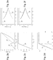
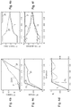
- Figures 2b to 2f show associated RF currents, voltages and efficiency curves relating to the embodiment of Figure 2a . It is noted that in Figure 2d the curve labelled 11 1 is the efficiency curve in a scale of 0 to 1, while the curve 11 2 is the same efficiency curve but magnified to help illustrate its characteristics.
- the auxiliary amplifier 31 is the one that is active in the lowermost amplitude region.
- the whole upper region above about 1/3 amplitude consists of almost perfect outphasing behavior, with extremely low phase differences between sub-amplifiers currents and voltages.
- the RF current amplitude of the auxiliary amplifier first diminishes until at amplitude 0.5 it starts increasing again.
- the relative efficiency (linear model) is above 99.9% in the whole region above 0.34 of full amplitude.
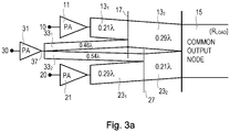
- Figure 3a shows an example of an amplifier circuit according to another embodiment of the present invention.
- the amplifier circuit comprises a first amplifier 11 configured to amplify a first input signal 10. An output of the first amplifier 11 is coupled to an output node 15 via a first transmission line 13.
- the first transmission line 13 comprises a first portion 13 1 having a first characteristic impedance and a first length, and a second portion 13 2 having a second characteristic impedance and a second length.
- the amplifier circuit also comprises a second amplifier 21 configured to amplify a second input signal 20.
- An output of the second amplifier 21 is coupled to the output node 15 via a second transmission line 23.
- the second transmission line 23 comprises a first portion 23 1 having a first characteristic impedance and a first length, and a second portion 23 2 having a second characteristic impedance and a second length.
- the amplifier circuit also comprises an auxiliary amplifier 31 (also referred to herein as a peaking amplifier) configured to amplify a third input signal 30.
- An output of the auxiliary amplifier 31 is coupled via an auxiliary transmission line network (33 1 , 33 2 ) to a first intersection 17 between the first and second portions 13 1 , 13 2 of the first transmission line 13, and to a second intersection 27 between the first and second portions 23 1 , 23 2 of the second transmission line 23.
- the first and second portions consist of a higher-impedance portion and a lower-impedance portion whose combined length is a half wavelength.
- the lengths of the respective first portions 13 1 , 23 1 of the first and second transmission lines 13, 23 also sum to half a wavelength
- the lengths of the respective second portions 13 2 , 23 2 of the first and second transmission lines 13, 23 also sum to half a wavelength
- the first amplifier 11 and the second amplifier 21 are of substantially the same size, and the auxiliary amplifier 31 reduced in size compared to the first and second amplifiers, for example 80% of the size of the others.
- the first transmission line 13 comprises a first portion 13 1 having an electrical length of 0.21 ⁇ , and a second portion 13 2 having an electrical length of 0.29 ⁇ , such that the sum of the electrical lengths is 0.5 ⁇ .
- the lengths of the respective first portions 13 1 , 23 1 of the first and second transmission lines 13, 23, i.e. 0.21 ⁇ for the first portion 13 1 and 0.29 ⁇ for the first portion 23 1 sum to half a wavelength
- the lengths of the respective second portions 13 2 , 23 2 of the first and second transmission lines 13, 23 also sum to half a wavelength, i.e. the sum of 0.29 ⁇ and 0.21 ⁇ .
- the auxiliary transmission line network comprises first and second auxiliary transmission lines 33 1 and 33 2 for coupling the auxiliary amplifier 31 to the first and second intersections of the first and second transmission lines 13, 23.
- the length of each of the first and second auxiliary transmission lines 33 1 , 33 2 is three quarters of a wavelength minus the length of the second portion 13 2 , 23 2 of the respective transmission line which connects the auxiliary transmission line to the output.
- the auxiliary transmission line 33 1 is therefore 0.46 ⁇ (i.e. 0.75 ⁇ minus the length 0.29 ⁇ of the second portion 13 2 of the first transmission line 13).
- the auxiliary transmission line 33 2 is therefore 0.54 ⁇ (i.e. 0.75 ⁇ minus the length 0.21 ⁇ of the second portion 23 2 of the second transmission line 23).
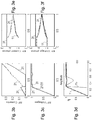
- Figures 3b to 3f show associated RF currents, voltages and efficiency curves relating to the embodiment of Figure 3a . It is noted that in Figure 3d the curve labelled 11 1 is the efficiency curve in a scale of 0 to 1, while the curve 11 2 is the same efficiency curve but magnified to help illustrate its characteristics.
- Figure 4a shows an example of an amplifier according to another embodiment of the present invention.
- the amplifier circuit comprises a first amplifier 11 configured to amplify a first input signal 10. An output of the first amplifier 11 is coupled to an output node 15 via a first transmission line 13.
- the first transmission line 13 comprises a first portion 13 1 having a first characteristic impedance and a first length, and a second portion 13 2 having a second characteristic impedance and a second length.
- the amplifier circuit also comprises a second amplifier 21 configured to amplify a second input signal 20.
- An output of the second amplifier 21 is coupled to the output node 15 via a second transmission line 23.
- the second transmission line 23 comprises a first portion 23 1 having a first characteristic impedance and a first length, and a second portion 23 2 having a second characteristic impedance and a second length.
- the amplifier circuit also comprises an auxiliary amplifier 31 (also referred to herein as a peaking amplifier) configured to amplify a third input signal 30.
- An output of the auxiliary amplifier 31 is coupled via an auxiliary transmission line network (33 1 , 33 2 ) to a first intersection 17 between the first and second portions 13 1 , 13 2 of the first transmission line 13, and to a second intersection 27 between the first and second portions 23 1 , 23 2 of the second transmission line 23.
- the first and second portions consist of a higher-impedance portion and a lower-impedance portion whose combined length is a half wavelength.
- the lengths of the respective first portions 13 1 , 23 1 of the first and second transmission lines 13, 23 also sum to half a wavelength
- the lengths of the respective second portions 13 2 , 23 2 of the first and second transmission lines 13, 23 also sum to half a wavelength
- the first amplifier 11, the second amplifier 21 and the auxiliary amplifier 31 are of substantially the same size.
- the first transmission line 13 comprises a first portion 13 1 having an electrical length of 0.21 ⁇ , and a second portion 13 2 having an electrical length of 0.29 ⁇ , such that the sum of the electrical lengths is 0.5 ⁇ .
- the lengths of the respective first portions 13 1 , 23 1 of the first and second transmission lines 13, 23, i.e. 0.21 ⁇ for the first portion 13 1 and 0.29 ⁇ for the first portion 23 1 sum to half a wavelength
- the lengths of the respective second portions 13 2 , 23 2 of the first and second transmission lines 13, 23 also sum to half a wavelength, i.e. the sum of 0.29 ⁇ and 0.21 ⁇ .
- Figures 4b to 4f show associated RF currents, voltages and efficiency curves relating to the embodiment of Figure 4a . It is noted that in Figure 4d the curve labelled 11 1 is the efficiency curve in a scale of 0 to 1, while the curve 11 2 is the same efficiency curve but magnified to help illustrate its characteristics.
- the auxiliary transmission line network comprises first and second auxiliary transmission lines 33 1 and 33 2 for coupling the auxiliary amplifier 31 to the first and second intersections of the first and second transmission lines 13, 23.
- the length of each of the first and second auxiliary transmission lines 33 1 , 33 2 is three quarters of a wavelength minus the length of the second portion 13 2 , 23 2 of the respective transmission line which connects the auxiliary transmission line to the output.
- the auxiliary transmission line 33 1 is therefore 0.46 ⁇ (i.e. 0.75 ⁇ minus the length 0.29 ⁇ of the second portion 13 2 of the first transmission line 13).
- the auxiliary transmission line 33 2 is therefore 0.54 ⁇ (i.e. 0.75 ⁇ minus the length 0.21 ⁇ of the second portion 23 2 of the second transmission line 23).
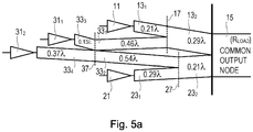
- auxiliary amplifier 31 is replaced with a Chireix pair 31 1 , 31 2 to form an efficient 4-stage amplifier.
- the auxiliary amplifier 31 comprises first and second auxiliary amplifiers 31 1 , 31 2 , and wherein the first auxiliary amplifier 31 1 is coupled via a third auxiliary transmission line 33 3 to an auxiliary junction 37, and the second auxiliary amplifier 31 2 coupled via a fourth auxiliary transmission line 33 4 to the auxiliary junction 37.
- the length of the third auxiliary transmission line 33 3 and fourth auxiliary transmission line 33 4 sum to half a wavelength.
- the length of the third auxiliary transmission line 33 3 is 0.13 ⁇ and the length of the fourth auxiliary transmission line 33 4 is 0.37 ⁇ , thereby summing to 0.5 ⁇ .
- the auxiliary transmission line network also comprises first and second auxiliary transmission lines 33 1 and 33 2 for coupling the first and second auxiliary amplifier 31 1 , 31 2 to the first and second intersections of the first and second transmission lines 13, 23.
- the length of each of the first and second auxiliary transmission lines 33 1 , 33 2 is three quarters of a wavelength minus the length of the second portion 13 2 , 23 2 of the respective transmission line which connects the auxiliary transmission line to the output.
- the first auxiliary transmission line 33 1 is therefore 0.46 ⁇ (i.e. 0.75 ⁇ minus the length 0.29 ⁇ of the second portion 13 2 of the first transmission line 13).
- the second auxiliary transmission line 33 2 is therefore 0.54 ⁇ (i.e. 0.75 ⁇ minus the length 0.21 ⁇ of the second portion 23 2 of the second transmission line 23).
- first amplifier 11, second amplifier 21, first auxiliary amplifier 31 1 and second auxiliary amplifier 31 2 are of substantially the same size.
- the Chireix pair 31 1 , 31 2 make it possible to extend the region of high efficiency to lower amplitudes, increasing the efficiency for high PAR signals.
- the amplifier circuit comprises a first amplifier 11 configured to amplify a first input signal 10.
- An output of the first amplifier 11 is coupled to an output node 15 via a first transmission line 13.
- the first transmission line 13 comprises a first portion 13 1 having a first characteristic impedance and a first length, and a second portion 13 2 having a second characteristic impedance and a second length.
- the amplifier circuit also comprises a second amplifier 21 configured to amplify a second input signal 20.
- An output of the second amplifier 21 is coupled to the output node 15 via a second transmission line 23.
- the second transmission line 23 comprises a first portion 23 1 having a first characteristic impedance and a first length, and a second portion 23 2 having a second characteristic impedance and a second length.
- the first and second portions consist of a higher-impedance portion and a lower-impedance portion whose combined length is a half wavelength.
- the lengths of the respective first portions 13 1 , 23 1 of the first and second transmission lines 13, 23 also sum to half a wavelength
- the lengths of the respective second portions 13 2 , 23 2 of the first and second transmission lines 13, 23 also sum to half a wavelength
- the first transmission line 13 comprises a first portion 13 1 having an electrical length of 0.21 ⁇ , and a second portion 13 2 having an electrical length of 0.29 ⁇ , such that the sum of the electrical lengths is 0.5 ⁇ .
- the lengths of the respective first portions 13 1 , 23 1 of the first and second transmission lines 13, 23, i.e. 0.21 ⁇ for the first portion 13 1 and 0.29 ⁇ for the first portion 23 1 sum to half a wavelength
- the lengths of the respective second portions 13 2 , 23 2 of the first and second transmission lines 13, 23 also sum to half a wavelength, i.e. the sum of 0.29 ⁇ and 0.21 ⁇ .
- Figures 5b to 5f show associated RF currents, voltages and efficiency curves relating to the embodiment of Figure 5a . It is noted that in Figure 5d the curve labelled 11 1 is the efficiency curve in a scale of 0 to 1, while the curve 11 2 is the same efficiency curve but magnified to help illustrate its characteristics.
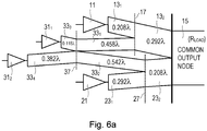
- the first amplifier 11 and second amplifier 21 are of substantially the same size, and wherein the first auxiliary amplifier 31 1 and second auxiliary amplifier 31 2 are of substantially the same size but smaller than the first and second amplifiers 11, 21.
- the first auxiliary amplifier 31 1 and second auxiliary amplifier 31 2 are about 80% of the size of the first and second amplifiers 11, 21. It is noted that other ratios may also be used.
- the amplifier circuit comprises a first amplifier 11 configured to amplify a first input signal 10.
- An output of the first amplifier 11 is coupled to an output node 15 via a first transmission line 13.
- the first transmission line 13 comprises a first portion 13 1 having a first characteristic impedance and a first length, and a second portion 13 2 having a second characteristic impedance and a second length.
- the amplifier circuit also comprises a second amplifier 21 configured to amplify a second input signal 20.
- An output of the second amplifier 21 is coupled to the output node 15 via a second transmission line 23.
- the second transmission line 23 comprises a first portion 23 1 having a first characteristic impedance and a first length, and a second portion 23 2 having a second characteristic impedance and a second length.
- the first and second portions consist of a higher-impedance portion and a lower-impedance portion whose combined length is a half wavelength.
- the lengths of the respective first portions 13 1 , 23 1 of the first and second transmission lines 13, 23 also sum to half a wavelength
- the lengths of the respective second portions 13 2 , 23 2 of the first and second transmission lines 13, 23 also sum to half a wavelength
- the first transmission line 13 comprises a first portion 13 1 having an electrical length of 0.208 ⁇ , and a second portion 13 2 having an electrical length of 0.292 ⁇ , such that the sum of the electrical lengths is 0.5 ⁇ .
- the lengths of the respective first portions 13 1 , 23 1 of the first and second transmission lines 13, 23, i.e. 0.208 ⁇ for the first portion 13 1 and 0.292 ⁇ for the first portion 23 1 sum to half a wavelength
- the lengths of the respective second portions 13 2 , 23 2 of the first and second transmission lines 13, 23 also sum to half a wavelength, i.e. the sum of 0.292 ⁇ and 0.208 ⁇ .
- the auxiliary transmission line network also comprises first and second auxiliary transmission lines 33 1 and 33 2 for coupling the first and second auxiliary amplifiers 31 1 , 31 2 to the first and second intersections 17, 27 of the first and second transmission lines 13, 23.
- the length of each of the first and second auxiliary transmission lines 33 1 , 33 2 is three quarters of a wavelength minus the length of the second portion 13 2 , 23 2 of the respective transmission line which connects the auxiliary transmission line to the output.
- the auxiliary transmission line 33 1 is therefore 0.458 ⁇ (i.e. 0.75 ⁇ minus the length 0.292 ⁇ of the second portion 13 2 of the first transmission line 13).
- the auxiliary transmission line 33 2 is therefore 0.542 ⁇ (i.e. 0.75 ⁇ minus the length 0.208 ⁇ of the second portion 23 2 of the second transmission line 23).
- the auxiliary amplifier 31 comprises first and second auxiliary amplifiers 31 1 , 31 2 , and wherein the first auxiliary amplifier 31 1 is coupled via a third auxiliary transmission line 33 3 to an auxiliary junction 37, and the second auxiliary amplifier 31 2 coupled via a fourth auxiliary transmission line 33 4 to the auxiliary junction 37.
- the length of the third auxiliary transmission line 33 3 and fourth auxiliary transmission line 33 4 sum to half a wavelength, whereby the length of the third auxiliary transmission line 33 3 is 0.118 ⁇ and the length of the fourth auxiliary transmission line 33 4 is 0.382 ⁇ , thereby summing to 0.5 ⁇ .
- the length from the auxiliary junction 37 to the output node 15 is a "constant", for example 0.75 ⁇ in these embodiments, while the sum of lengths from the Chireix pair amplifiers 31 1 and 31 2 to the auxiliary junction 37 is 0.5 ⁇ .
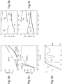
- Figures 6b to 6f show associated RF currents, voltages and efficiency curves relating to the embodiment of Figure 6a . It is noted that in Figure 6d the curve labelled 11 1 is the efficiency curve in a scale of 0 to 1, while the curve 11 2 is the same efficiency curve but magnified to help illustrate its characteristics.
- the reverse size relation between the Chireix pairs (i.e. between the first and second auxiliary amplifiers 31 1 /31 2 and the other first and second amplifiers 11/21) is also possible. Different sized pairs are also useful when the available transistor sizes do not provide the correct peak power with 4-equal dimensioning.
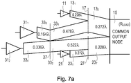
- An example of a reverse configuration with an amplifier with 2-to-1 sub-amplifier size relations is shown in Figure 7a .
- the amplifier circuit according to this example has been dimensioned for larger possible PAR values.
- the amplifier circuit comprises a first amplifier 11 configured to amplify a first input signal 10.
- An output of the first amplifier 11 is coupled to an output node 15 via a first transmission line 13.
- the first transmission line 13 comprises a first portion 13 1 having a first characteristic impedance and a first length, and a second portion 13 2 having a second characteristic impedance and a second length.
- the amplifier circuit also comprises a second amplifier 21 configured to amplify a second input signal 20.
- An output of the second amplifier 21 is coupled to the output node 15 via a second transmission line 23.
- the second transmission line 23 comprises a first portion 23 1 having a first characteristic impedance and a first length, and a second portion 23 2 having a second characteristic impedance and a second length.
- the first and second portions consist of a higher-impedance portion and a lower-impedance portion whose combined length is a half wavelength.
- the lengths of the respective first portions 13 1 , 23 1 of the first and second transmission lines 13, 23 also sum to half a wavelength
- the lengths of the respective second portions 13 2 , 23 2 of the first and second transmission lines 13, 23 also sum to half a wavelength
- the first transmission line 13 comprises a first portion 13 1 having an electrical length of 0.228 ⁇ , and a second portion 13 2 having an electrical length of 0.272 ⁇ , such that the sum of the electrical lengths is 0.5 ⁇ .
- the lengths of the respective first portions 13 1 , 23 1 of the first and second transmission lines 13, 23, i.e. 0.228 ⁇ for the first portion 13 1 and 0.272 ⁇ for the first portion 23 1 sum to half a wavelength
- the lengths of the respective second portions 13 2 , 23 2 of the first and second transmission lines 13, 23 also sum to half a wavelength, i.e. the sum of 0.272 ⁇ and 0.228 ⁇ .
- the auxiliary transmission line network also comprises first and second auxiliary transmission lines 33 1 and 33 2 for coupling the first and second auxiliary amplifiers 31 1 , 31 2 to the first and second intersections 17, 27 of the first and second transmission lines 13, 23.
- the length of each of the first and second auxiliary transmission lines 33 1 , 33 2 is three quarters of a wavelength minus the length of the second portion 13 2 , 23 2 of the respective transmission line which connects the auxiliary transmission line to the output.
- the auxiliary transmission line 33 1 is therefore 0.478 ⁇ (i.e. 0.75 ⁇ minus the length 0.272 ⁇ of the second portion 13 2 of the first transmission line 13).
- the auxiliary transmission line 33 2 is therefore 0.522 ⁇ (i.e. 0.75 ⁇ minus the length 0.228 ⁇ of the second portion 23 2 of the second transmission line 23).
- the auxiliary amplifier 31 comprises first and second auxiliary amplifiers 31 1 , 31 2 , and wherein the first auxiliary amplifier 31 1 is coupled via a third auxiliary transmission line 33 3 to an auxiliary junction 37, and the second auxiliary amplifier 31 2 coupled via a fourth auxiliary transmission line 33 4 to the auxiliary junction 37.
- the length of the third auxiliary transmission line 33 3 is 0.164 ⁇ and the length of the fourth auxiliary transmission line 33 4 is 0.336 ⁇ .
- the length of the third auxiliary transmission line 33 3 and fourth auxiliary transmission line 33 4 sum to half a wavelength.
- the first amplifier 11 and second amplifier 21 are of substantially the same size, and wherein the first auxiliary amplifier 31 1 and second auxiliary amplifier 31 2 are of substantially the same size but larger than the first and second amplifiers 11, 21.
- the first amplifier 11 and second auxiliary amplifier 21 can be about 50% of the size of the first and second auxiliary amplifiers 31 1 , 31 2 .
- Figure 8a shows an example according to another embodiment, whereby a fourth amplifier 41 is connected directly (or connected by a half wavelength line) to the output 15, in an amplifier circuit similar to that of Figure 1 .
- the amplifier circuit comprises a first amplifier 11 configured to amplify a first input signal 10.
- An output of the first amplifier 11 is coupled to an output node 15 via a first transmission line 13.
- the first transmission line 13 comprises a first portion 13 1 having a first characteristic impedance and a first length, and a second portion 13 2 having a second characteristic impedance and a second length.
- the amplifier circuit also comprises a second amplifier 21 configured to amplify a second input signal 20.
- An output of the second amplifier 21 is coupled to the output node 15 via a second transmission line 23.
- the second transmission line 23 comprises a first portion 23 1 having a first characteristic impedance and a first length, and a second portion 23 2 having a second characteristic impedance and a second length.
- the amplifier circuit also comprises an auxiliary amplifier 31 (also referred to herein as a peaking amplifier) configured to amplify a third input signal 30.
- An output of the auxiliary amplifier 31 is coupled via an auxiliary transmission line network (33 1 , 33 2 ) to a first intersection 17 between the first and second portions 13 1 , 13 2 of the first transmission line 13, and to a second intersection 27 between the first and second portions 23 1 , 23 2 of the second transmission line 23.
- the amplifier circuit also comprises a fourth amplifier 41 coupled directly (or connected by a half wavelength line) to the output 15.
- the first and second portions consist of a higher-impedance portion and a lower-impedance portion whose combined length is a half wavelength.
- the lengths of the respective first portions 13 1 , 23 1 of the first and second transmission lines 13, 23 also sum to half a wavelength
- the lengths of the respective second portions 13 2 , 23 2 of the first and second transmission lines 13, 23 also sum to half a wavelength
- the first transmission line 13 comprises a first portion 13 1 having an electrical length of 0.2 ⁇ , and a second portion 13 2 having an electrical length of 0.3 ⁇ , such that the sum of the electrical lengths is 0.5 ⁇ .
- the lengths of the respective first portions 13 1 , 23 1 of the first and second transmission lines 13, 23, i.e. 0.2 ⁇ for the first portion 13 1 and 0.3 ⁇ for the first portion 23 1 sum to half a wavelength
- the lengths of the respective second portions 13 2 , 23 2 of the first and second transmission lines 13, 23 also sum to half a wavelength, i.e. the sum of 0.3 ⁇ and 0.2 ⁇ .
- the auxiliary transmission line network comprises first and second auxiliary transmission lines 33 1 and 33 2 for coupling the auxiliary amplifier 31 to the first and second intersections 17, 27 of the first and second transmission lines 13, 23.
- the length of each of the first and second auxiliary transmission lines 33 1 , 33 2 is three quarters of a wavelength minus the length of the second portion 13 2 , 23 2 of the respective transmission line which connects the auxiliary transmission line to the output.
- the auxiliary transmission line 33 1 is therefore 0.45 ⁇ (i.e. 0.75 ⁇ minus the length 0.3 ⁇ of the second portion 13 2 of the first transmission line 13).
- the auxiliary transmission line 33 2 is therefore 0.55 ⁇ (i.e. 0.75 ⁇ minus the length 0.2 ⁇ of the second portion 23 2 of the second transmission line 23).
- Figures 8b to 8f show associated RF currents, voltages and efficiency curves relating to the embodiment of Figure 8a . It is noted that in Figure 8d the curve labelled 11 1 is the efficiency curve in a scale of 0 to 1, while the curve 11 2 is the same efficiency curve but magnified to help illustrate its characteristics.
- Figure 9 shows the steps performed in an amplifier circuit by a method according to another embodiment of the present invention.
- the method comprises the steps of amplifying a first input signal 10 using a first amplifier 11, and coupling the amplified first input signal to an output node 15 via a first transmission line 13, the first transmission line 13 comprising a first portion 13 1 having a first characteristic impedance and a first length, and a second portion 13 2 having a second characteristic impedance and a second length, step 1001.
- the method further comprises the step of amplifying a second input signal 20 using a second amplifier, and coupling the amplified second input signal to the output node via a second transmission line, the second transmission line comprising a first portion having a first characteristic impedance and a first length, and a second portion having a second characteristic impedance and a second length, step 1003.
- the method further comprises the step of amplifying a third input signal 30 using an auxiliary amplifier, and coupling the output of the auxiliary amplifier via an auxiliary transmission line network to a first intersection between the first and second portions of the first transmission line, and to a second intersection between the first and second portions of the second transmission line, step 1005.
- the first and second portions consist of a higher-impedance portion and a lower-impedance portion whose combined length is a half wavelength, step 1007.
- the lengths of the respective first portions of the first and second transmission lines sum to half a wavelength, and the lengths of the respective second portions of the first and second transmission lines sum to half a wavelength, step 1009.
- Transistors in general act as controlled RF current sources, so the shape of the amplitudes and phases (relative to that of the output) of the RF currents as functions of the output amplitude also suggest the desired voltage shaping that can be performed to the input signals (gate drive voltages).
- the actual shapes can take into account that the voltage-to-current conversion (transconductance) in the transistors is more or less nonlinear, and that the RF voltage swing can influence the output current as well (especially via saturation when close to the upper limit).
- the quarter wave lines can be replaced by LC, pi- or T-networks with reactances equal in magnitude to the characteristic impedance of the replaced quarter wave line.
- T networks, L networks, single or in cascade can also be used, for example a line slightly shorter than a quarter wavelength can be synthesized by a quarter wavelength line with shunt inductors (coupled to RF ground) at each side, and a line longer than a quarter wavelength can be synthesized by a quarter wavelength line with shunt capacitors at each side.
- the 3-stage amplifier circuits according to embodiments of the present invention offer close to optimal Chireix outphasing between all three amplifiers (sub-amplifiers) in the upper 9.5 dB amplitude range, with better than 99.9% linear model efficiency.
- the 4-stage amplifier circuits according to embodiments of the present invention have very good efficiency in wide amplitude ranges, also when different size sub-amplifier pairs are employed.
- the amplifier circuits of the present invention are particularly suitable when transistors with very low shunt loss are employed, such as Laterally Diffused Metal Oxide Semiconductor (LDMOS) transistors at relatively low frequencies, or at higher frequencies with Gallium Nitride (GaN) or Gallium Arsenide (GaA) transistors.
- LDMOS Laterally Diffused Metal Oxide Semiconductor
- GaN Gallium Nitride
- GaA Gallium Arsenide
- a characteristic impedance of a first portion is higher that the characteristic impedance of a second portion, e.g. 13 2 , of a transmission line, as represented by the relative thicknesses of the transmission lines (the smaller the thickness the higher the characteristic impedance, and vice versa.
- the characteristic impedance of a first portion of a first transmission line may be substantially N times the characteristic impedance of a second portion of the first transmission line and/or the characteristic impedance of a first portion of a second transmission line may be substantially N times the characteristic impedance of a second portion of a second transmission line.
Landscapes
- Engineering & Computer Science (AREA)
- Power Engineering (AREA)
- Microwave Amplifiers (AREA)
- Amplifiers (AREA)
Claims (17)
- Verstärkerschaltung, umfassend:einen ersten Verstärker (11), der zum Verstärken eines ersten Eingangssignals (10) ausgelegt ist, wobei ein Ausgang des ersten Verstärkers (11) über eine erste Übertragungsleitung (13) mit einem Ausgangsknoten (15) gekoppelt ist, die erste Übertragungsleitung (13) einen ersten Abschnitt (131) mit einer ersten charakteristischen Impedanz und einer ersten Länge und einen zweiten Abschnitt (132) mit einer zweiten charakteristischen Impedanz und einer zweiten Länge umfasst;einen zweiten Verstärker (21), der zum Verstärken eines zweiten Eingangssignals (20) ausgelegt ist, wobei ein Ausgang des ersten Verstärkers (21) über eine zweite Übertragungsleitung (23) mit dem Ausgangsknoten (15) gekoppelt ist, die zweite Übertragungsleitung (23) einen ersten Abschnitt (231) mit einer ersten charakteristischen Impedanz und einer ersten Länge und einen zweiten Abschnitt (232) mit einer zweiten charakteristischen Impedanz und einer zweiten Länge umfasst; undeinen Hilfsverstärker (31; 311, 312), der zum Verstärken eines dritten Eingangssignals (30) ausgelegt ist, wobei ein Ausgang des Hilfsverstärkers (31; 311, 312) über ein Hilfsübertragungsleitungsnetz (331, 332; 333, 334) mit einer ersten Kreuzungsstelle (17) zwischen den ersten und zweiten Abschnitten (131, 132) der ersten Übertragungsleitung (13) und mit einer zweiten Kreuzungsstelle (27) zwischen den ersten und zweiten Abschnitten (231, 232) der zweiten Übertragungsleitung (23) gekoppelt ist;wobei für jede der ersten und zweiten Übertragungsleitungen (13, 23) die ersten und zweiten Abschnitte (131, 132; 231, 232) aus einem Abschnitt höherer Impedanz und einem Abschnitt niedrigerer Impedanz bestehen, deren kombinierte Länge eine halbe Wellenlänge ist; undwobei die Längen der jeweiligen ersten Abschnitte (131, 231) der ersten und zweiten Übertragungsleitungen (13, 23) eine halbe Wellenlänge summieren, und die Längen der jeweiligen zweiten Abschnitte (132, 232) der ersten und zweiten Übertragungsleitungen (13, 23) eine halbe Wellenlänge summieren.
- Verstärkerschaltung nach Anspruch 1, wobei die Länge des ersten Abschnitts (131) der ersten Übertragungsleitung (13) im Wesentlichen gleich der Länge des zweiten Abschnitts (232) der zweiten Übertragungsleitung (23) ist, und/oder wobei die Länge des ersten Abschnitts (231) der zweiten Übertragungsleitung (23) im Wesentlichen gleich der Länge des zweiten Abschnitts (132) der ersten Übertragungsleitung (13) ist.
- Verstärkerschaltung nach Anspruch 1 oder 2, wobei das Hilfsübertragungsleitungsnetz erste und zweite Hilfsübertragungsleitungen (331 und 332) zum Koppeln des Hilfsverstärkers (31) mit den ersten und zweiten Kreuzungsstellen (17, 27) der ersten und zweiten Übertragungsleitungen (13, 23) umfasst, und wobei die Länge jeder der ersten und zweiten Hilfsübertragungsleitungen (331, 332) drei Viertel einer Wellenlänge minus der Länge des zweiten Abschnitts (132, 232) der jeweiligen Übertragungsleitung ist, welche die Hilfsübertragungsleitung mit dem Ausgang verbindet.
- Verstärkerschaltung nach Anspruch 4, wobei die Gesamtlänge vom Hilfsverstärker (31) zum Ausgang (15) durch einen beliebigen Pfad Dreiviertelwellenlängen entspricht.
- Verstärkerschaltung nach einem der vorhergehenden Ansprüche, wobei der erste Verstärker (11), der zweite Verstärker (21) und der Hilfsverstärker (31) im Wesentlichen die gleiche Größe aufweisen.
- Verstärkerschaltung nach einem der Ansprüche 1 bis 4, wobei der erste Verstärker (11) und der zweite Verstärker (21) im Wesentlichen die gleiche Größe aufweisen, und der Hilfsverstärker (31) gegenüber den ersten und zweiten Verstärkern (11, 21) eine reduzierte Größe aufweist.
- Verstärkerschaltung nach Anspruch 6, wobei der Hilfsverstärker (31) eine Größe aufweist, die gegenüber den ersten und zweiten Verstärkern (11, 21) um etwa 80 % reduziert ist.
- Verstärkerschaltung nach einem der vorhergehenden Ansprüche, wobei der Hilfsverstärker (31) direkt oder durch eine Halbwellenlängen-Übertragungsleitung mit dem Hilfsübertragungsleitungsnetz gekoppelt ist.
- Verstärkerschaltung nach einem der vorhergehenden Ansprüche, wobei der Hilfsverstärker (31) erste und zweite Hilfsverstärker (311, 312) umfasst, und wobei der erste Hilfsverstärker (311) über eine dritte Hilfsübertragungsleitung (333) mit einem Hilfsübergang (37) gekoppelt ist, und der zweite Hilfsverstärker (312) über eine vierte Hilfsübertragungsleitung (334) mit dem Hilfsübergang (37) gekoppelt ist.
- Verstärkerschaltung nach Anspruch 9, wobei die Länge der dritten Hilfsübertragungsleitung (333) und der vierten Hilfsübertragungsleitung (334) eine halbe Wellenlänge summieren.
- Verstärkerschaltung nach Anspruch 9 oder 10, wobei der erste Verstärker (11), der zweite Verstärker (21), der erste Hilfsverstärker (311) und der zweite Hilfsverstärker (312) im Wesentlichen die gleiche Größe aufweisen.
- Verstärkerschaltung nach einem der Ansprüche 9 bis 10, wobei der erste Verstärker (11) und der zweite Verstärker (21) im Wesentlichen die gleiche Größe aufweisen, und der erste Hilfsverstärker (311) und der zweite Hilfsverstärker (312) im Wesentlichen die gleiche Größe aufweisen, aber kleiner als die ersten und zweiten Verstärkern (11, 21) sind.
- Verstärkerschaltung nach Anspruch 12, wobei der erste Hilfsverstärker (311) und der zweite Hilfsverstärker (312) etwa 80 % der Größe der ersten und zweiten Verstärkern (11, 21) sind.
- Verstärkerschaltung nach Anspruch 9 oder 10, wobei der erste Verstärker (11) und der zweite Verstärker (21) im Wesentlichen die gleiche Größe aufweisen, und der erste Hilfsverstärker (311) und der zweite Hilfsverstärker (312) im Wesentlichen die gleiche Größe aufweisen, aber größer als die ersten und zweiten Verstärkern (11, 21) sind.
- Verstärkerschaltung nach Anspruch 14, wobei der erste Hilfsverstärker (11) und der zweite Hilfsverstärker (21) etwa 50 % der Größe der ersten und zweiten Hilfsverstärkern (311, 312) sind.
- Verstärkerschaltung nach einem der Ansprüche 1 bis 8, ferner umfassend einen vierten Verstärker (41), der zum Verstärken eines vierten Eingangssignals (40) ausgelegt ist, wobei ein Ausgang des vierten Verstärkers (41) entweder direkt oder über eine Übertragungsleitung einer halben Wellenlänge oder einer Vielfachen davon mit dem Ausgangsknoten (15) gekoppelt ist.
- Verfahren in einer Verstärkerschaltung, wobei das Verfahren die folgenden Schritte umfasst:Verstärken eines ersten Eingangssignals (10) unter Verwendung eines ersten Verstärkers (11) und Einkoppeln des verstärkten ersten Eingangssignals über eine erste Übertragungsleitung (13) in einen Ausgangsknoten (15), wobei die erste Übertragungsleitung (13) einen ersten Abschnitt (131) mit einer ersten charakteristischen Impedanz und einer ersten Länge und einen zweiten Abschnitt (132) mit einer zweiten charakteristischen Impedanz und einer zweiten Länge umfasst (Schritt 1001);Verstärken eines zweiten Eingangssignals (20) unter Verwendung eines zweiten Verstärkers (21) und Einkoppeln des verstärkten zweiten Eingangssignals über eine zweite Übertragungsleitung (23) in den Ausgangsknoten (15), wobei die zweite Übertragungsleitung (23) einen ersten Abschnitt (231) mit einer ersten charakteristischen Impedanz und einer ersten Länge und einen zweiten Abschnitt (232) mit einer zweiten charakteristischen Impedanz und einer zweiten Länge umfasst (Schritt 1003); undVerstärken eines dritten Eingangssignals (30) unter Verwendung eines Hilfsverstärkers (31; 311, 312) und Einkoppeln der Ausgabe des Hilfsverstärkers (31; 311, 312) über ein Hilfsübertragungsleitungsnetz (331, 332; 333, 334) in eine erste Kreuzungsstelle (17) zwischen den ersten und zweiten Abschnitten (131, 132) der ersten Übertragungsleitung (13) und in eine zweite Kreuzungsstelle (27) zwischen den ersten und zweiten Abschnitten (231, 232) der zweiten Übertragungsleitung (23) (Schritt 1005);wobei für jede der ersten und zweiten Übertragungsleitungen (13, 23) die ersten und zweiten Abschnitte (131, 132; 231, 232) aus einem Abschnitt höherer Impedanz und einem Abschnitt niedrigerer Impedanz bestehen, deren kombinierte Länge eine halbe Wellenlänge ist; undwobei die Längen der jeweiligen ersten Abschnitte (131, 231) der ersten und zweiten Übertragungsleitungen (13, 23) eine halbe Wellenlänge summieren, und die Längen der jeweiligen zweiten Abschnitte (132, 232) der ersten und zweiten Übertragungsleitungen (13, 23) eine halbe Wellenlänge summieren.
Applications Claiming Priority (1)
| Application Number | Priority Date | Filing Date | Title |
|---|---|---|---|
| PCT/SE2014/050566 WO2015171027A1 (en) | 2014-05-08 | 2014-05-08 | Amplifier circuit and method |
Publications (2)
| Publication Number | Publication Date |
|---|---|
| EP3140908A1 EP3140908A1 (de) | 2017-03-15 |
| EP3140908B1 true EP3140908B1 (de) | 2018-02-21 |
Family
ID=50877644
Family Applications (1)
| Application Number | Title | Priority Date | Filing Date |
|---|---|---|---|
| EP14727643.0A Active EP3140908B1 (de) | 2014-05-08 | 2014-05-08 | Verstärkerschaltung und verfahren |
Country Status (4)
| Country | Link |
|---|---|
| US (1) | US9577584B2 (de) |
| EP (1) | EP3140908B1 (de) |
| CN (1) | CN106416062B (de) |
| WO (1) | WO2015171027A1 (de) |
Families Citing this family (2)
| Publication number | Priority date | Publication date | Assignee | Title |
|---|---|---|---|---|
| US9484863B2 (en) | 2014-05-08 | 2016-11-01 | Telefonaktiebolaget Lm Ericsson (Publ) | Amplifier circuit and method |
| MX382691B (es) * | 2016-04-11 | 2025-03-13 | Ericsson Telefon Ab L M | Sistema amplificador de potencia modular y escalable. |
Family Cites Families (18)
| Publication number | Priority date | Publication date | Assignee | Title |
|---|---|---|---|---|
| US5111157A (en) * | 1991-05-01 | 1992-05-05 | General Electric Company | Power amplifier for broad band operation at frequencies above one ghz and at decade watt power levels |
| DE60217188T2 (de) | 2002-09-06 | 2007-10-04 | Telefonaktiebolaget Lm Ericsson (Publ) | Zusammengesetzter leistungsverstärker |
| ATE422108T1 (de) | 2002-12-19 | 2009-02-15 | Ericsson Telefon Ab L M | Zusammengesetzte verstärkerstruktur |
| US7061315B2 (en) | 2003-06-06 | 2006-06-13 | Anaren, Inc. | Auxiliary amplifier network |
| FR2858492B1 (fr) | 2003-07-31 | 2006-09-08 | Cit Alcatel | Amplificateur a grande dynamique de puissance de sortie |
| CN101103524B (zh) | 2004-12-21 | 2010-05-05 | 艾利森电话股份有限公司 | 功率放大器系统 |
| US7382186B2 (en) | 2005-01-24 | 2008-06-03 | Triquint Semiconductor, Inc. | Amplifiers with high efficiency in multiple power modes |
| JP4858952B2 (ja) * | 2005-05-23 | 2012-01-18 | 株式会社日立国際電気 | 増幅装置 |
| JP5001435B2 (ja) * | 2007-12-21 | 2012-08-15 | エヌエックスピー ビー ヴィ | 出力回路網を最小にした3ウェイドハティ増幅器 |
| US8441321B2 (en) | 2008-12-09 | 2013-05-14 | Telefonaktiebolaget L M Ericsson (Publ) | Multi-stage amplifier |
| WO2010074615A1 (en) | 2008-12-22 | 2010-07-01 | Telefonaktiebolaget L M Ericsson (Publ) | A multi stage amplifier |
| KR101124425B1 (ko) | 2010-01-20 | 2012-03-22 | 포항공과대학교 산학협력단 | 분포 도허티 전력 증폭기 |
| EP2362541A1 (de) * | 2010-02-25 | 2011-08-31 | Alcatel Lucent | Parallelverstärker |
| EP2748925B1 (de) | 2011-12-15 | 2015-09-23 | Telefonaktiebolaget L M Ericsson (publ) | Vorrichtung und verfahren zur verwendung mit einer verstärkerschaltung |
| EP2608400B1 (de) | 2011-12-20 | 2014-08-13 | Nxp B.V. | N-Weg-Doherty-Verstärker |
| US8717099B2 (en) * | 2012-03-16 | 2014-05-06 | Infineon Technologies Ag | Wideband doherty amplifier circuit with peaking impedance absorption |
| US8653889B1 (en) * | 2012-09-06 | 2014-02-18 | Alcatel Lucent | Doherty amplifier having compact output matching and combining networks |
| EP3005556B1 (de) | 2013-05-27 | 2018-11-21 | Telefonaktiebolaget LM Ericsson (publ) | Verstärkerschaltung und verfahren |
-
2014
- 2014-05-08 EP EP14727643.0A patent/EP3140908B1/de active Active
- 2014-05-08 CN CN201480078787.1A patent/CN106416062B/zh active Active
- 2014-05-08 US US14/406,799 patent/US9577584B2/en not_active Expired - Fee Related
- 2014-05-08 WO PCT/SE2014/050566 patent/WO2015171027A1/en not_active Ceased
Also Published As
| Publication number | Publication date |
|---|---|
| EP3140908A1 (de) | 2017-03-15 |
| WO2015171027A1 (en) | 2015-11-12 |
| US9577584B2 (en) | 2017-02-21 |
| US20160218680A1 (en) | 2016-07-28 |
| CN106416062B (zh) | 2019-05-28 |
| CN106416062A (zh) | 2017-02-15 |
Similar Documents
| Publication | Publication Date | Title |
|---|---|---|
| US9712118B2 (en) | Amplifier circuit and method | |
| EP1985012B1 (de) | Leistungsverstärker | |
| EP2374210B1 (de) | Mehrstufiger verstärker | |
| US8115546B2 (en) | Apparatus and method for maximizing performance of peaking amplifier in doherty amplifier | |
| EP3205015B1 (de) | Verstärkerschaltung und verfahren | |
| US11223327B2 (en) | Power amplifier | |
| US9941851B2 (en) | Amplifier circuit and method | |
| EP3140908B1 (de) | Verstärkerschaltung und verfahren | |
| EP3140907B1 (de) | Verstärkerschaltung und verfahren | |
| EP2748925B1 (de) | Vorrichtung und verfahren zur verwendung mit einer verstärkerschaltung | |
| US9866190B2 (en) | Multi-stage amplifiers with low loss | |
| EP2413498A1 (de) | Doherty-Verstärker | |
| US10193503B2 (en) | Amplifier circuit and method | |
| EP3443664B1 (de) | Modulares und skalierbares leistungsverstärkersystem | |
| KR101654927B1 (ko) | 광대역 도허티 전력 증폭기 | |
| JP2020516192A (ja) | 広帯域電力増幅器装置 | |
| US9954492B2 (en) | Amplifier circuit and method |
Legal Events
| Date | Code | Title | Description |
|---|---|---|---|
| PUAI | Public reference made under article 153(3) epc to a published international application that has entered the european phase |
Free format text: ORIGINAL CODE: 0009012 |
|
| 17P | Request for examination filed |
Effective date: 20161004 |
|
| AK | Designated contracting states |
Kind code of ref document: A1 Designated state(s): AL AT BE BG CH CY CZ DE DK EE ES FI FR GB GR HR HU IE IS IT LI LT LU LV MC MK MT NL NO PL PT RO RS SE SI SK SM TR |
|
| AX | Request for extension of the european patent |
Extension state: BA ME |
|
| DAX | Request for extension of the european patent (deleted) | ||
| REG | Reference to a national code |
Ref country code: DE Ref legal event code: R079 Ref document number: 602014021212 Country of ref document: DE Free format text: PREVIOUS MAIN CLASS: H03F0003600000 Ipc: H03F0003680000 |
|
| GRAP | Despatch of communication of intention to grant a patent |
Free format text: ORIGINAL CODE: EPIDOSNIGR1 |
|
| RIC1 | Information provided on ipc code assigned before grant |
Ipc: H03F 3/68 20060101AFI20170920BHEP Ipc: H03F 3/60 20060101ALI20170920BHEP Ipc: H03F 3/19 20060101ALI20170920BHEP Ipc: H03F 1/02 20060101ALI20170920BHEP |
|
| RIN1 | Information on inventor provided before grant (corrected) |
Inventor name: HELLBERG, RICHARD |
|
| INTG | Intention to grant announced |
Effective date: 20171024 |
|
| GRAJ | Information related to disapproval of communication of intention to grant by the applicant or resumption of examination proceedings by the epo deleted |
Free format text: ORIGINAL CODE: EPIDOSDIGR1 |
|
| GRAR | Information related to intention to grant a patent recorded |
Free format text: ORIGINAL CODE: EPIDOSNIGR71 |
|
| GRAS | Grant fee paid |
Free format text: ORIGINAL CODE: EPIDOSNIGR3 |
|
| GRAA | (expected) grant |
Free format text: ORIGINAL CODE: 0009210 |
|
| INTC | Intention to grant announced (deleted) | ||
| AK | Designated contracting states |
Kind code of ref document: B1 Designated state(s): AL AT BE BG CH CY CZ DE DK EE ES FI FR GB GR HR HU IE IS IT LI LT LU LV MC MK MT NL NO PL PT RO RS SE SI SK SM TR |
|
| INTG | Intention to grant announced |
Effective date: 20180116 |
|
| REG | Reference to a national code |
Ref country code: GB Ref legal event code: FG4D |
|
| REG | Reference to a national code |
Ref country code: CH Ref legal event code: EP |
|
| REG | Reference to a national code |
Ref country code: AT Ref legal event code: REF Ref document number: 972752 Country of ref document: AT Kind code of ref document: T Effective date: 20180315 |
|
| REG | Reference to a national code |
Ref country code: IE Ref legal event code: FG4D |
|
| REG | Reference to a national code |
Ref country code: DE Ref legal event code: R096 Ref document number: 602014021212 Country of ref document: DE |
|
| REG | Reference to a national code |
Ref country code: FR Ref legal event code: PLFP Year of fee payment: 5 |
|
| REG | Reference to a national code |
Ref country code: NL Ref legal event code: MP Effective date: 20180221 |
|
| REG | Reference to a national code |
Ref country code: LT Ref legal event code: MG4D |
|
| REG | Reference to a national code |
Ref country code: AT Ref legal event code: MK05 Ref document number: 972752 Country of ref document: AT Kind code of ref document: T Effective date: 20180221 |
|
| PG25 | Lapsed in a contracting state [announced via postgrant information from national office to epo] |
Ref country code: ES Free format text: LAPSE BECAUSE OF FAILURE TO SUBMIT A TRANSLATION OF THE DESCRIPTION OR TO PAY THE FEE WITHIN THE PRESCRIBED TIME-LIMIT Effective date: 20180221 Ref country code: NO Free format text: LAPSE BECAUSE OF FAILURE TO SUBMIT A TRANSLATION OF THE DESCRIPTION OR TO PAY THE FEE WITHIN THE PRESCRIBED TIME-LIMIT Effective date: 20180521 Ref country code: HR Free format text: LAPSE BECAUSE OF FAILURE TO SUBMIT A TRANSLATION OF THE DESCRIPTION OR TO PAY THE FEE WITHIN THE PRESCRIBED TIME-LIMIT Effective date: 20180221 Ref country code: LT Free format text: LAPSE BECAUSE OF FAILURE TO SUBMIT A TRANSLATION OF THE DESCRIPTION OR TO PAY THE FEE WITHIN THE PRESCRIBED TIME-LIMIT Effective date: 20180221 Ref country code: CY Free format text: LAPSE BECAUSE OF FAILURE TO SUBMIT A TRANSLATION OF THE DESCRIPTION OR TO PAY THE FEE WITHIN THE PRESCRIBED TIME-LIMIT Effective date: 20180221 Ref country code: NL Free format text: LAPSE BECAUSE OF FAILURE TO SUBMIT A TRANSLATION OF THE DESCRIPTION OR TO PAY THE FEE WITHIN THE PRESCRIBED TIME-LIMIT Effective date: 20180221 Ref country code: FI Free format text: LAPSE BECAUSE OF FAILURE TO SUBMIT A TRANSLATION OF THE DESCRIPTION OR TO PAY THE FEE WITHIN THE PRESCRIBED TIME-LIMIT Effective date: 20180221 |
|
| PG25 | Lapsed in a contracting state [announced via postgrant information from national office to epo] |
Ref country code: GR Free format text: LAPSE BECAUSE OF FAILURE TO SUBMIT A TRANSLATION OF THE DESCRIPTION OR TO PAY THE FEE WITHIN THE PRESCRIBED TIME-LIMIT Effective date: 20180522 Ref country code: AT Free format text: LAPSE BECAUSE OF FAILURE TO SUBMIT A TRANSLATION OF THE DESCRIPTION OR TO PAY THE FEE WITHIN THE PRESCRIBED TIME-LIMIT Effective date: 20180221 Ref country code: SE Free format text: LAPSE BECAUSE OF FAILURE TO SUBMIT A TRANSLATION OF THE DESCRIPTION OR TO PAY THE FEE WITHIN THE PRESCRIBED TIME-LIMIT Effective date: 20180221 Ref country code: LV Free format text: LAPSE BECAUSE OF FAILURE TO SUBMIT A TRANSLATION OF THE DESCRIPTION OR TO PAY THE FEE WITHIN THE PRESCRIBED TIME-LIMIT Effective date: 20180221 Ref country code: RS Free format text: LAPSE BECAUSE OF FAILURE TO SUBMIT A TRANSLATION OF THE DESCRIPTION OR TO PAY THE FEE WITHIN THE PRESCRIBED TIME-LIMIT Effective date: 20180221 Ref country code: BG Free format text: LAPSE BECAUSE OF FAILURE TO SUBMIT A TRANSLATION OF THE DESCRIPTION OR TO PAY THE FEE WITHIN THE PRESCRIBED TIME-LIMIT Effective date: 20180521 |
|
| PG25 | Lapsed in a contracting state [announced via postgrant information from national office to epo] |
Ref country code: PL Free format text: LAPSE BECAUSE OF FAILURE TO SUBMIT A TRANSLATION OF THE DESCRIPTION OR TO PAY THE FEE WITHIN THE PRESCRIBED TIME-LIMIT Effective date: 20180221 Ref country code: IT Free format text: LAPSE BECAUSE OF FAILURE TO SUBMIT A TRANSLATION OF THE DESCRIPTION OR TO PAY THE FEE WITHIN THE PRESCRIBED TIME-LIMIT Effective date: 20180221 Ref country code: EE Free format text: LAPSE BECAUSE OF FAILURE TO SUBMIT A TRANSLATION OF THE DESCRIPTION OR TO PAY THE FEE WITHIN THE PRESCRIBED TIME-LIMIT Effective date: 20180221 Ref country code: AL Free format text: LAPSE BECAUSE OF FAILURE TO SUBMIT A TRANSLATION OF THE DESCRIPTION OR TO PAY THE FEE WITHIN THE PRESCRIBED TIME-LIMIT Effective date: 20180221 Ref country code: RO Free format text: LAPSE BECAUSE OF FAILURE TO SUBMIT A TRANSLATION OF THE DESCRIPTION OR TO PAY THE FEE WITHIN THE PRESCRIBED TIME-LIMIT Effective date: 20180221 |
|
| REG | Reference to a national code |
Ref country code: DE Ref legal event code: R097 Ref document number: 602014021212 Country of ref document: DE |
|
| PG25 | Lapsed in a contracting state [announced via postgrant information from national office to epo] |
Ref country code: CZ Free format text: LAPSE BECAUSE OF FAILURE TO SUBMIT A TRANSLATION OF THE DESCRIPTION OR TO PAY THE FEE WITHIN THE PRESCRIBED TIME-LIMIT Effective date: 20180221 Ref country code: SK Free format text: LAPSE BECAUSE OF FAILURE TO SUBMIT A TRANSLATION OF THE DESCRIPTION OR TO PAY THE FEE WITHIN THE PRESCRIBED TIME-LIMIT Effective date: 20180221 Ref country code: SM Free format text: LAPSE BECAUSE OF FAILURE TO SUBMIT A TRANSLATION OF THE DESCRIPTION OR TO PAY THE FEE WITHIN THE PRESCRIBED TIME-LIMIT Effective date: 20180221 Ref country code: DK Free format text: LAPSE BECAUSE OF FAILURE TO SUBMIT A TRANSLATION OF THE DESCRIPTION OR TO PAY THE FEE WITHIN THE PRESCRIBED TIME-LIMIT Effective date: 20180221 |
|
| REG | Reference to a national code |
Ref country code: CH Ref legal event code: PL |
|
| PLBE | No opposition filed within time limit |
Free format text: ORIGINAL CODE: 0009261 |
|
| STAA | Information on the status of an ep patent application or granted ep patent |
Free format text: STATUS: NO OPPOSITION FILED WITHIN TIME LIMIT |
|
| 26N | No opposition filed |
Effective date: 20181122 |
|
| REG | Reference to a national code |
Ref country code: BE Ref legal event code: MM Effective date: 20180531 |
|
| PG25 | Lapsed in a contracting state [announced via postgrant information from national office to epo] |
Ref country code: MC Free format text: LAPSE BECAUSE OF FAILURE TO SUBMIT A TRANSLATION OF THE DESCRIPTION OR TO PAY THE FEE WITHIN THE PRESCRIBED TIME-LIMIT Effective date: 20180221 |
|
| REG | Reference to a national code |
Ref country code: IE Ref legal event code: MM4A |
|
| PG25 | Lapsed in a contracting state [announced via postgrant information from national office to epo] |
Ref country code: CH Free format text: LAPSE BECAUSE OF NON-PAYMENT OF DUE FEES Effective date: 20180531 Ref country code: LI Free format text: LAPSE BECAUSE OF NON-PAYMENT OF DUE FEES Effective date: 20180531 Ref country code: SI Free format text: LAPSE BECAUSE OF FAILURE TO SUBMIT A TRANSLATION OF THE DESCRIPTION OR TO PAY THE FEE WITHIN THE PRESCRIBED TIME-LIMIT Effective date: 20180221 |
|
| PG25 | Lapsed in a contracting state [announced via postgrant information from national office to epo] |
Ref country code: LU Free format text: LAPSE BECAUSE OF NON-PAYMENT OF DUE FEES Effective date: 20180508 |
|
| PG25 | Lapsed in a contracting state [announced via postgrant information from national office to epo] |
Ref country code: IE Free format text: LAPSE BECAUSE OF NON-PAYMENT OF DUE FEES Effective date: 20180508 |
|
| PG25 | Lapsed in a contracting state [announced via postgrant information from national office to epo] |
Ref country code: BE Free format text: LAPSE BECAUSE OF NON-PAYMENT OF DUE FEES Effective date: 20180531 |
|
| PG25 | Lapsed in a contracting state [announced via postgrant information from national office to epo] |
Ref country code: MT Free format text: LAPSE BECAUSE OF NON-PAYMENT OF DUE FEES Effective date: 20180508 |
|
| PG25 | Lapsed in a contracting state [announced via postgrant information from national office to epo] |
Ref country code: TR Free format text: LAPSE BECAUSE OF FAILURE TO SUBMIT A TRANSLATION OF THE DESCRIPTION OR TO PAY THE FEE WITHIN THE PRESCRIBED TIME-LIMIT Effective date: 20180221 |
|
| PG25 | Lapsed in a contracting state [announced via postgrant information from national office to epo] |
Ref country code: PT Free format text: LAPSE BECAUSE OF FAILURE TO SUBMIT A TRANSLATION OF THE DESCRIPTION OR TO PAY THE FEE WITHIN THE PRESCRIBED TIME-LIMIT Effective date: 20180221 |
|
| PG25 | Lapsed in a contracting state [announced via postgrant information from national office to epo] |
Ref country code: MK Free format text: LAPSE BECAUSE OF NON-PAYMENT OF DUE FEES Effective date: 20180221 Ref country code: HU Free format text: LAPSE BECAUSE OF FAILURE TO SUBMIT A TRANSLATION OF THE DESCRIPTION OR TO PAY THE FEE WITHIN THE PRESCRIBED TIME-LIMIT; INVALID AB INITIO Effective date: 20140508 |
|
| PG25 | Lapsed in a contracting state [announced via postgrant information from national office to epo] |
Ref country code: IS Free format text: LAPSE BECAUSE OF FAILURE TO SUBMIT A TRANSLATION OF THE DESCRIPTION OR TO PAY THE FEE WITHIN THE PRESCRIBED TIME-LIMIT Effective date: 20180621 |
|
| PGFP | Annual fee paid to national office [announced via postgrant information from national office to epo] |
Ref country code: DE Payment date: 20250529 Year of fee payment: 12 |
|
| PGFP | Annual fee paid to national office [announced via postgrant information from national office to epo] |
Ref country code: GB Payment date: 20250527 Year of fee payment: 12 |
|
| PGFP | Annual fee paid to national office [announced via postgrant information from national office to epo] |
Ref country code: FR Payment date: 20250526 Year of fee payment: 12 |