EP3140918B1 - Architecture mimo massive - Google Patents
Architecture mimo massive Download PDFInfo
- Publication number
- EP3140918B1 EP3140918B1 EP15723405.5A EP15723405A EP3140918B1 EP 3140918 B1 EP3140918 B1 EP 3140918B1 EP 15723405 A EP15723405 A EP 15723405A EP 3140918 B1 EP3140918 B1 EP 3140918B1
- Authority
- EP
- European Patent Office
- Prior art keywords
- signals
- processing
- processing elements
- antennas
- different
- Prior art date
- Legal status (The legal status is an assumption and is not a legal conclusion. Google has not performed a legal analysis and makes no representation as to the accuracy of the status listed.)
- Active
Links
Images






Classifications
-
- H—ELECTRICITY
- H04—ELECTRIC COMMUNICATION TECHNIQUE
- H04B—TRANSMISSION
- H04B7/00—Radio transmission systems, i.e. using radiation field
- H04B7/02—Diversity systems; Multi-antenna system, i.e. transmission or reception using multiple antennas
- H04B7/04—Diversity systems; Multi-antenna system, i.e. transmission or reception using multiple antennas using two or more spaced independent antennas
- H04B7/0413—MIMO systems
- H04B7/0456—Selection of precoding matrices or codebooks, e.g. using matrices antenna weighting
-
- H—ELECTRICITY
- H04—ELECTRIC COMMUNICATION TECHNIQUE
- H04B—TRANSMISSION
- H04B7/00—Radio transmission systems, i.e. using radiation field
- H04B7/02—Diversity systems; Multi-antenna system, i.e. transmission or reception using multiple antennas
- H04B7/022—Site diversity; Macro-diversity
- H04B7/024—Co-operative use of antennas of several sites, e.g. in co-ordinated multipoint or co-operative multiple-input multiple-output [MIMO] systems
-
- H—ELECTRICITY
- H04—ELECTRIC COMMUNICATION TECHNIQUE
- H04B—TRANSMISSION
- H04B7/00—Radio transmission systems, i.e. using radiation field
- H04B7/02—Diversity systems; Multi-antenna system, i.e. transmission or reception using multiple antennas
- H04B7/04—Diversity systems; Multi-antenna system, i.e. transmission or reception using multiple antennas using two or more spaced independent antennas
- H04B7/0413—MIMO systems
-
- H—ELECTRICITY
- H04—ELECTRIC COMMUNICATION TECHNIQUE
- H04B—TRANSMISSION
- H04B7/00—Radio transmission systems, i.e. using radiation field
- H04B7/02—Diversity systems; Multi-antenna system, i.e. transmission or reception using multiple antennas
- H04B7/04—Diversity systems; Multi-antenna system, i.e. transmission or reception using multiple antennas using two or more spaced independent antennas
- H04B7/0413—MIMO systems
- H04B7/0452—Multi-user MIMO systems
-
- H—ELECTRICITY
- H04—ELECTRIC COMMUNICATION TECHNIQUE
- H04L—TRANSMISSION OF DIGITAL INFORMATION, e.g. TELEGRAPHIC COMMUNICATION
- H04L5/00—Arrangements affording multiple use of the transmission path
- H04L5/003—Arrangements for allocating sub-channels of the transmission path
- H04L5/0048—Allocation of pilot signals, i.e. of signals known to the receiver
-
- H—ELECTRICITY
- H04—ELECTRIC COMMUNICATION TECHNIQUE
- H04L—TRANSMISSION OF DIGITAL INFORMATION, e.g. TELEGRAPHIC COMMUNICATION
- H04L7/00—Arrangements for synchronising receiver with transmitter
- H04L7/0008—Synchronisation information channels, e.g. clock distribution lines
- H04L7/0012—Synchronisation information channels, e.g. clock distribution lines by comparing receiver clock with transmitter clock
-
- H—ELECTRICITY
- H04—ELECTRIC COMMUNICATION TECHNIQUE
- H04L—TRANSMISSION OF DIGITAL INFORMATION, e.g. TELEGRAPHIC COMMUNICATION
- H04L7/00—Arrangements for synchronising receiver with transmitter
- H04L7/0016—Arrangements for synchronising receiver with transmitter correction of synchronization errors
- H04L7/002—Arrangements for synchronising receiver with transmitter correction of synchronization errors correction by interpolation
- H04L7/0025—Arrangements for synchronising receiver with transmitter correction of synchronization errors correction by interpolation interpolation of clock signal
-
- H—ELECTRICITY
- H04—ELECTRIC COMMUNICATION TECHNIQUE
- H04W—WIRELESS COMMUNICATION NETWORKS
- H04W56/00—Synchronisation arrangements
-
- H—ELECTRICITY
- H04—ELECTRIC COMMUNICATION TECHNIQUE
- H04W—WIRELESS COMMUNICATION NETWORKS
- H04W56/00—Synchronisation arrangements
- H04W56/001—Synchronization between nodes
-
- H—ELECTRICITY
- H04—ELECTRIC COMMUNICATION TECHNIQUE
- H04W—WIRELESS COMMUNICATION NETWORKS
- H04W88/00—Devices specially adapted for wireless communication networks, e.g. terminals, base stations or access point devices
- H04W88/08—Access point devices
-
- H—ELECTRICITY
- H04—ELECTRIC COMMUNICATION TECHNIQUE
- H04W—WIRELESS COMMUNICATION NETWORKS
- H04W88/00—Devices specially adapted for wireless communication networks, e.g. terminals, base stations or access point devices
- H04W88/08—Access point devices
- H04W88/085—Access point devices with remote components
Definitions
- This disclosure relates to wireless communication systems and more particularly to multiple input, multiple output (MIMO) communications.
- MIMO multiple input, multiple output
- Massive MIMO is an exciting theoretical area of 5G wireless that promises significant gains that offer the ability to accommodate more users, at higher data rates, with better reliability, while consuming less power.
- Conventional MIMO base stations typically use six or eight antennas in a sectorized topology, but massive MIMO base stations utilize more than eight antennas (and sometimes as many as 128, 256, or more) while massive MIMO user equipment devices (UEs) may typically utilize around eight antennas.
- massive MIMO reduces power in a given channel by focusing the energy to targeted mobile users using precoding techniques. By directing the wireless energy to specific users, the power in channel is reduced and, at the same time, interference to other users is decreased.
- conventional data networks may use LTE or LTE-Advanced, which in turn use the pilot tones in an orthogonal frequency division multiplexing (OFDM) waveform to estimate the channel condition.
- OFDM orthogonal frequency division multiplexing
- a massive MIMO system may essentially run out of unique pilot tones for a receiver to effectively detect and resolve channel conditions. Further, processing and synchronization requirements for massive MIMO may be difficult to meet using conventional systems.
- EP 2 278 731 A2 discloses a MIMO system that supports multiple spatial multiplexing modes for improved performance and greater flexibility. These modes may include a single-user steered mode that transmits multiple data streams on orthogonal spatial channels to a single receiver, a single-user non-steered mode that transmits multiple data streams from multiple antennas to a single receiver without spatial processing at a transmitter, a multi-user steered mode that transmits multiple data streams simultaneously to multiple receivers with spatial processing at a transmitter, and a multi-user non-steered mode that transmits multiple data streams from multiple antennas (co-located or non co-located) without spatial processing at the transmitter(s) to receiver(s) having multiple antennas.; For each set of user terminal(s) selected for data transmission on the downlink and/or uplink, a spatial multiplexing mode is selected for the user terminal set from among the multiple spatial multiplexing modes supported by the system.
- WO 2013/133645 A1 discloses a method for performing hierarchical beamforming in a wireless access system and a device therefor. Particularly, the method comprises: an initial step for allowing a base station to transmit a plurality of first beams, to which different steering vector are applied, to a terminal through corresponding reference signals; and a repetition step for allowing the base station to transmit a plurality of second beams, to which different steering vectors are applied, to the terminal through corresponding reference signals by considering feedback information that contains an index of one or more beams received from the terminal, wherein the repetition step can be repeated up to a predetermined number of times.
- the invention is defined by a base station according to claim 1, a method according to claim 8 and a computer program according to claim 15.
- a base station includes a plurality of antennas, a plurality of processing elements coupled to the plurality of antennas and configured to perform processing for wireless communications via the plurality of antennas, and an interconnect configured to couple the plurality of processing elements.
- the base station is configured to combine signals received by multiple antennas.
- each processing element is configured to operate on a different portion of the combined signals, where each portion includes signals from multiple antennas.
- a large antenna count system includes a master device, a plurality of slave radios communicatively coupled to the master device and to respective antennas in the large antenna clock system, and a clock and trigger distribution system, coupled to the master device and the plurality of slave radios.
- each slave includes a local clock and the clock and trigger distribution system comprises a hierarchy of clock and trigger distribution modules.
- the plurality of slave radios are configured to establish and maintain a fixed relationship between a reference clock and their respective local clocks, where the reference clock is distributed via the clock and trigger distribution system.
- the master device and the plurality of slave radios are configured to generate and align respective common periodic time reference signals that have a lower frequency than the respective local clocks.
- the master device is configured to transmit, based on an edge of its common periodic time reference signal, a trigger signal via the clock and trigger distribution system to the plurality of slave radios.
- the plurality of slave radios are configured to perform an action based on the trigger at a subsequent edge of their common periodic time reference signals.
- the master device is configured similarly to the slave devices, at least in the sense that it also includes a local clock, is configured to establish and maintain a fixed relationship between a reference clock and its local clock, and is configured to perform an action based on the trigger at the subsequent edge of its common period time reference signal.
- an apparatus includes a plurality of antennas, a plurality of radios configured to perform wireless communication with one or more mobile devices, and one or more processing elements coupled to the plurality of radios.
- the apparatus is configured to receive an uplink pilot symbol from a mobile device over a first channel, receive uplink data from the mobile device over the first channel, where the uplink data is included in one or more orthogonal frequency division multiplexing (OFDM) symbols at a symbol rate, determine channel information based on the pilot symbol, precode downlink data based on the channel information, and transmit, via one or more of the plurality of antennas, the precoded downlink data to the mobile device.
- OFDM orthogonal frequency division multiplexing
- a transition interval between receiving the uplink pilot symbol and beginning to transmit the precoded downlink data corresponds to less than five OFDM symbols at the symbol rate.
- MIMO multiple-input multiple-output
- a massive MIMO system is configured as a versatile, flexible, and scalable massive MIMO platform for real-time, two-way communication.
- the disclosed systems and techniques may be used in a production environment and/or in test environments.
- Fig. 1 shows an exemplary MIMO system 100 that includes base station 102 and M mobile devices 106A-M (which may also be referred to as user equipment devices or UEs 106AM).
- base station 102 includes N antennas configured to transmit and receive data with mobile devices 106 using time-division duplexing (TDD).
- TDD time-division duplexing
- FDD frequency-division duplexing
- mobile devices 106 may concurrently communicate with base station 102 via wireless propagation environment.
- the paths taken by different signals may vary among the mobile devices, e.g., based on their location in the environment. Therefore, using MIMO techniques to precode signals transmitted by the base station, for example, may greatly improve overall radio capacity, performance, and/or range.
- base station 102 may allocate multiple antennas (e.g., as many as ten or more in some massive MIMO systems) to a given mobile device 10.
- mobile devices may concurrently transmit a known pattern to the base station in a particular time or frequency slot.
- Base station 102 may compare the pattern across a number of antennas to determine the unique channel characteristics to each spatially diverse path for the different UEs. Subsequently, the base station may apply the inverse of channel characteristic parameters as a form of precoding, such that each mobile device 106 receives its intended messages.
- base station 102 is configured to exploit the reciprocity of the channel between base station 102 and a given mobile device 106 by using uplink channel conditions (for communications from one or more of the mobile devices 106 to the base station 102) to configure downlink transmissions (from the base station 102 to at least one of the mobile devices 106).
- the precoder is formed using channel estimates.
- Common precoders include zero forcing (ZF) and minimum mean squared error (MMSE).
- ZF zero forcing
- MMSE minimum mean squared error
- MRT maximum ratio transmission
- MIMO techniques may increase capacity, performance, and/or range of wireless communications. Although various embodiments are discussed herein in the context of cellular communications, these embodiments are not intended to limit the scope of the present disclosure. Rather, the disclosed techniques may be used in various wireless communication contexts, such as WIFI, for example.
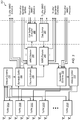
- Fig. 2 shows exemplary send and receive chains for reciprocity-based MIMO for two antennas, which may be included in MIMO base station 102, for example.
- analog-to-digital (A/D) converters 212A-N demodulate and digitize received uplink signals from RF.
- Down-samplers 214A-N down-sample the digital samples to a desired sampling rate, e.g., that is some fraction of the A/D sampling rate.
- units 216A-N, 218A-N, 220A-N, and 222A-N perform OFDM signal processing, including removing the cyclic prefix (CP), performing a Fast Fourier Transform (FFT) after serial-to-parallel conversion, removing guard subcarriers, and de-allocating uplink data and pilots to the resource map.
- Base station 102 may then pass pilot and data symbols for all N receive chains to channel estimator 250.
- Channel estimates generated by channel estimator 250 are used by MIMO decoder 240 to decode M uplink data streams and by MIMO precoder 260 to precode M downlink data streams.
- the precoded downlink data streams are then processed by units 224A-N, 226A-N, 228A-N, and 230A-N, including resource mapping, adding guard symbols, serial-to parallel conversion, performing an inverse FFT, and adding the cyclic prefix. Subsequently, units 232A-N up-convert the data from the baseband rate and digital to analog converters (D/As) 234A-N convert the result for transmission via the antennas.
- D/As digital to analog converters
- Various disclosed techniques address challenges when adding a large number of receive and transmit chains to a system, as in massive MIMO.
- software defined radios are used to implement a massive MIMO system that is configurable, modular, meets I/O requirements for distributed processing, and supports real-time processing for large numbers of antennas.
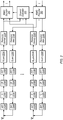
- Fig. 3 is a block diagram illustrating a subsystem of one embodiment of a massive MIMO system 300.
- System 300 may be included in base station 102, for example.
- system 300 is configured to perform at least a portion of the processing described above with reference to Fig. 2 in a distributed manner.
- the subsystem includes front-end TX/RX units 302A-N, antenna combiner 310, antenna splitter 315, bandwidth splitter 320, bandwidth combiner 325, channel estimator 330, MIMO detector 340, and MIMO precoder 345.
- link quality evaluator 350 and data source 360 are included in a central control unit that is shared among multiple subsystems (as indicated by the vertical dashed lines, delineating units included in the central controller, according to this embodiment).
- MIMO processing in the illustrated embodiment, is distributed among various processing elements. This may allow baseband processing to be partitioned across multiple FPGAs, for example. This may facilitate scaling of massive MIMO systems far beyond what a single centralized processing unit could achieve for real-time baseband processing.
- TX/RX units 302A-N are included in software defined radio modules, which may also include processing elements configured or configurable to perform the functionality of various other units shown in Fig. 3 .
- TX/RX 302A and antenna combiner 310 may be implemented by the same SDR element.
- An exemplary embodiment of a peripheral configured to implement an SDR is discussed in further detail below with reference to Fig. 4 .
- each TX/RX 302 may be configured to digitize the received RF signals, perform analog front-end calibration and time/frequency synchronization, remove the cyclic prefix (CP), and perform FFT OFDM demodulation and guard-band removal. This may result in frequency domain pilot and unequalized data symbol vectors, which is provided to antenna combiner 310 in the illustrated embodiment. Note that, at this point, the OFDM symbols may contain the superposition of transmitted signals by all users.
- each TX/RX 302 may be configured to perform ODFM processing as described above with reference to Fig. 2 for signals received from antenna splitter 315.
- antenna combiner 310, bandwidth, splitter 320, MIMO precoder 345, bandwidth combiner 325, and antenna splitter 315 are each located on a different SDR element that also implements one of TX/RXs 302.
- channel estimator 330 and MIMO detector 340 are located on another SDR element that also implements one of TX/RXs 302.
- the various elements of Fig. 3 may be partitioned among various hardware elements configured to perform the disclosed functionality.
- the hardware elements may be programmable and/or include dedicated circuitry.
- Antenna combiner 310 in the illustrated embodiment, is configured to receive the yet unequalized OFDM symbols from each TX/RX 302 and combines them into a signal sent to bandwidth splitter 320. This combines the signals from up to N antennas in the subsystem. Combining this information before further processing may allow the system to stay within throughput constraints and may reduce the number of peer-to-peer connections between SDRs, for example. In some embodiments, the number of antennas for which signals are combined by each antenna combiner 310 is dynamically configurable.
- Bandwidth splitter 320 in the illustrated embodiment, is configured to split the received signals into separate bandwidth portions and send the portions to MIMO detectors in different subsystems.
- processing is distributed across different processing elements that each process data for a different frequency band.
- Each bandwidth portion may include one or more subcarriers and the portions may or may not be nonoverlapping.
- the number of bandwidth portions and the size of each portion is configurable, e.g., based on the number of antennas, current number of users in communication, etc.
- processing may be distributed among processing elements across different time slices in addition to and/or in place of splitting by frequency.
- bandwidth splitter 320 is replaced with a time-slice splitter.
- Post-FTT subcarrier processing in OFDM may be inherently independent, allowing subsequent processing to be performed in parallel by different processing elements.
- the output of TX/RX 302B is provided directly to bandwidth splitter 320 and an output of bandwidth combiner 325 is provided directly to TX/RX 302D. In other embodiments, these outputs may be provided to antenna combiner 310 and antenna splitter 315 similarly to the other signals. In embodiments in which TX/RX 302B and bandwidth splitter 320 share the same SDR element and TX/RX 302D and bandwidth combiner 325 share the same SDR element, however, the illustrated coupling may conserve I/O resources.
- MIMO detector 340 in the illustrated embodiment, is configured to use an estimated channel matrix (e.g., based on uplink pilot symbols) to cancel interference and detect frequency-domain symbols from each mobile device 106. As shown, in some embodiments MIMO detector 340 is configured to process signals in a given bandwidth from multiple subsystems of system 300. In the illustrated embodiment, MIMO detector 340 is configured to send the detected signals to channel estimator 330 and to link quality evaluator 350 (included in a central controller in some embodiments) for further processing.
- an estimated channel matrix e.g., based on uplink pilot symbols
- Channel estimator 330 in the illustrated embodiment, is configured to perform channel estimation for its frequency portion for a number of mobile devices, e.g., to produce soft-bits (also referred to as log-likelihood ratios (LLRs)) and provide them to link quality evaluator 350 (coupling not shown).
- soft-bits also referred to as log-likelihood ratios (LLRs)
- LLRs log-likelihood ratios
- multiple decoders are implemented, including a turbo decoder, for example.
- data source 360 in test system embodiments, is configured to generate test data, which may be pseudo-random or may be explicitly specified for a particular test.
- data source 360 may be located in a central control unit.
- data source 360 may provide data from various networks to be transmitted to mobile devices 106.
- MIMO precoder 345 in the illustrated embodiment, is configured to receive downlink data from data source 360 and precode the data based on channel estimates (e.g., estimated reciprocity calibration weights) from channel estimator 330.
- the MIMO precoders in system 300 are configured to perform precoding on different frequency portions of the downlink data.
- the MIMO precoders in system 300 are configured to perform precoding on different time portions of the downlink data.
- Exemplary precoders include maximum radio transmission (MRT) and zero forcing (ZF) precoders.
- MRT maximum radio transmission
- ZF zero forcing
- any of various appropriate precoding techniques may be implemented.
- varying amounts of processing for the precoding may be performed by at a central controller or distributed among MIMO precoders 345.
- Bandwidth combiner 325 in the illustrated embodiment, is configured to combine signals at different bandwidths from multiple MIMO precoders and send the data to antenna splitter 315. This may result in a complete set of precoded data for transmission from the separately processed bandwidth portions. In other embodiments, bandwidth combiner 325 is configured to combine data corresponding to separately-processed time slices in place of or in addition to combining separately-processed frequency portions.
- Antenna splitter 315 in the illustrated embodiment, is configured to split the received signal and provide the split signal to TX/RXs 302 for OFDM processing and transmission to mobile devices 106.
- the set of antennas to which antenna splitter 315 is configured to provide signals is dynamically configurable, in some embodiments (e.g., the number of antennas and/or the particular antennas in the set).
- the set of processing elements configured to perform distributed processing for particular antennas and/or users is dynamically configurable.
- Link quality evaluator 350 in the illustrated embodiment, is included in a central control unit and is configured to measure link quality using one or more of various metrics such as bit error rate (BER), error vector magnitude (EVM), and/or packet-error rate (PER).
- BER bit error rate
- EVM error vector magnitude
- PER packet-error rate
- system 300 is highly configurable, e.g., based on user input and/or current operating conditions. In some embodiments, various disclosed configuration operations are performed automatically. In some embodiments, the number of processing elements used at a given time to perform distributed processing for a set of users or a set of antennas is configurable. In some embodiments, the number of antennas used to communicate with each UE is configurable and/or dynamically determined. In some embodiments, the processing elements configured to perform different functionality described above is configurable. For example, the antenna combiner function may be moved from one FPGA to another FPGA or performed by multiple FPGAs. In some embodiments, the routing of data between processing elements is configurable, e.g., to avoid malfunctioning antennas and/or processing elements.
- system 300 is configured to adjust these configurable aspects dynamically based on current operating conditions.
- system 300 incudes a large number of antennas, e.g., more than 8.
- system 300 includes 16, 32, 64, 100, 128, 256, or more antennas.
- components of system 300 are modular such that the number of antennas may be increased by adding additional components.
- a software library is provided with system 300 and is configured with example test scenarios for configuring system 300.
- a graphical programming language such as Lab VIEW is used to configure programmable hardware devices in system 300.
- various functionality described herein may be configured using a graphical programming interface.
- Exemplary high-level system parameters include a system bandwidth of 20 MHz, a carrier frequency of 3.7 GHz, a sampling rate of 30.72 MS/s, and FFT size of 2048, 1200 used subcarriers, a 0.5 ms slot time, a 1 ms subframe time, a 10 ms frame time, and 100 antennas.
- These parameters are exemplary only and are not intended to limit the scope of the present disclosure.
- the parameters are user configurable and/or are dynamically configurable by the system itself.
- bandwidth splitter 320 is configured to separate and provide bandwidth portions of the incoming signals from multiple antennas in order to distribute processing load.
- the incoming signals maybe split in other dimensions in addition to and/or in place of the frequency dimension. Processing for downlink signals may be similarly distributed.
- the disclosed system is highly configurable and provides high-performance distributed processing to meet real-time performance requirements for massive MIMO systems.
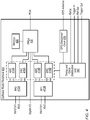
- Fig. 4 shows one embodiment of a software radio peripheral 400.
- the National Instruments® Universal Software Radio Peripheral (USRP) is one exemplary embodiment of a software radio peripheral 400.
- a software radio peripheral 400 is configured to implement one or more of TX/RXs 302 and one or more of antenna combiner 310, bandwidth splitter 320, channel estimator 330, MIMO detector 340, MIMO precoder 345, bandwidth combiner 325, and antenna splitter 315 of Fig. 3 .
- multiple software radio peripherals 400 are coupled via one or more interconnects to implement a massive MIMO base station.
- Software radio peripheral 400 includes radio frequency transceivers RF0 412A and RF1 412B, ADCs 414A-B, DACs 416A-B, memory 420, field-programmable gate array (FPGA) 430, timing and clock distribution unit 440, and GPS-disciplined clock 435.
- radio frequency transceivers RF0 412A and RF1 412B includes radio frequency transceivers RF0 412A and RF1 412B, ADCs 414A-B, DACs 416A-B, memory 420, field-programmable gate array (FPGA) 430, timing and clock distribution unit 440, and GPS-disciplined clock 435.
- FPGA field-programmable gate array
- RF transceivers RF0 412A and RF1 412B are configured to send and receive transmissions to one or more mobile devices 106 via one or more antennas.
- each transceiver is configured to utilize up to 40 MHz of radio frequency bandwidth at center frequencies of 1.2-6 GHz and is configured to transmit with up to 15 decibel-milliwatts (dBm).
- ADCs 414A-B and DACs 416A-B may be configured similarly to A/D 212A-N and D/A 234A-N as described above with reference to Fig. 2 . In some embodiments, these elements are respectively configured to convert received analog data to digital form and received digital information to analog form for wireless transmission.
- FPGA 430 in some embodiments, is a programmable hardware element configured to and/or configurable to perform various radio processing functionality. In some embodiments, FPGA 430 is configured to perform various MIMO processing described above with reference to Fig. 3 . For example, FPGA 430 may be configured to perform one or more of OFDM front-end processing (e.g., as discussed with reference to units 214, 216, 218, 220, 222, 224, 226, 228, 230, and 232 of Fig. 2 ), antenna combining, bandwidth splitting, MIMO detection, channel estimation, MIMO precoding, bandwidth combining, antenna splitting, etc.
- OFDM front-end processing e.g., as discussed with reference to units 214, 216, 218, 220, 222, 224, 226, 228, 230, and 232 of Fig. 2
- antenna combining bandwidth splitting
- MIMO detection channel estimation
- MIMO precoding bandwidth combining
- antenna splitting etc.
- FPGA 430 is coupled to ADCs 414A-B and DACs 416A-B, a digital I/O port, and a Peripheral Component Interconnect Express (PCIe) connection.
- PCIe Peripheral Component Interconnect Express
- software radio peripheral 400 is coupled to other software radio peripherals and/or a central control unit via PCIe (or any of various other appropriate couplings).
- a program may described as capable of causing or configuring a computing system to perform various operations. This encompasses both instructions that are executable by the computing system to cause the system to perform the operation(s) and instructions that are usable to configure the computing system (e.g., by configuring FPGA 430) such that it is capable of performing the operation(s) (note that the latter type of instructions may not be executed, but may be used to configure programmable circuitry, for example, which is then configured to perform the operation(s)).
- FPGA 430 may be replaced or supplemented with any of various appropriate processing elements.
- Memory 420 in some embodiments, is configured to facilitate programming of FPGA 430 and/or storing of values (e.g., sampled and processed uplink signals) during processing operations by FPGA 430.
- Memory 420 may include multiple different storage elements or a single storage element and may be implemented using various different memory technologies as appropriate.
- Timing and clock distribution unit 440 in the illustrated embodiment, is configured to receive information from GPS-disciplined clock 435, a reference signal input "ref in,” and/or a trigger input signal. In the illustrated embodiment, unit 440 is also configured to provide a reference output signal "ref out" and a trigger output signal. In some embodiments, described in further detail below with reference to Figs. 7-10 , one or more of these signals may be used to synchronize sampling and/or other operations by multiple software radio peripherals.
- GPS-disciplined clock 435 in the illustrated embodiment, is configured to receive global positioning system (GPS) signals and generate a clock signal for timing and clock distribution unit 440 that is disciplined to a GPS time.
- GPS global positioning system
- GPS is provided as one example of a reference clock, but in other embodiments, any of various appropriate reference clocks may be used, including clocks generated by satellite navigation systems other than GPS, etc.
- the reference signal input may be configured to receive a reference clock signal and the GPS-disciplined clock 435 is omitted, disabled, or ignored.
- Software radio peripheral 400 is provided as one example of a hardware module configured or configurable to implement a portion of the functionality of system 300.
- other processing elements such as a central processing unit or a non-FPGA programmable hardware element in addition to or in place of an FPGA may be used to perform similar operations.
- unit 400 is referred to as a "software" radio peripheral 400 in disclosed embodiments, it may also be a hardwired radio peripheral configured to perform similar functionality.
- software radio peripheral 400 is a plug-in module or card configured to be inserted into a chassis (such as a PCIe chassis for example) for communication with other modules.
- processing elements configured to perform similar functionality may be integrated or coupled into a massive MIMO system using other techniques.
- Software radio peripheral 400 is provided as one example of a hardware module configured to implement functionality of system 300.
- other processing elements such as processors or other programmable hardware elements in addition to or in place of an FPGA may be used to perform similar operations.
- unit 400 is referred to as a "software" radio peripheral 400 in disclosed embodiments, it may also be a hardwired radio peripheral configured to perform similar functionality.
- software radio peripheral 400 is a plug-in module or card configured to be inserted into a chassis (such as a PCIe chassis for example) for communication with other modules.
- processing elements configured to perform similar functionality may be integrated or coupled into a massive MIMO system using other techniques.
- the disclosed massive MIMO system performs within practical hardware I/O limits while providing a low-latency path for time-critical processing.
- the critical signal path is from receipt of OFDM symbols through channel estimation, MIMO precoding, and OFDM transmission. This path may be especially important for reciprocity-based MIMO.
- this path includes RX front-end delay, CP removal, FFT, guard subcarrier removal, channel estimation, precoder calculation, guard subcarrier interleave, IFFT, CP addition, and TX front-end delay. Additional sources of latency may include overhead in data routing, packing, unpacking, and hops across the PCIe backplane.
- this latency is reduced by using efficient routing mechanisms over a high speed communication bus (such as PCIe, for example).
- a high degree of pipelining (which may be enabled by packing data antennas-first) and the disclosed combining data from multiple antennas and then splitting it based on bandwidth before distributing the data for processing, as shown in Fig. 3 , allows the number of antennas and the overall system bandwidth to be scaled upwards almost indefinitely.
- Pipelining in various embodiments, may allow different sets of data (e.g., data sampled from the antennas at different times) to reside in different processing stages. For example, one FPGA may perform bandwidth splitting, then pass the data on to another FPGA for MIMO detection before splitting a subsequent set of data, in a pipelined fashion. Referring back to Fig. 3 , various units may be configured to operate in a pipelined and distributed manner.
- Fig. 5 shows one embodiment of a system 500 that includes hardware configured to implement a massive MIMO base station.
- system 500 includes clock module(s) 510, chassis 520A-N, SRPs 400A-Q, and central controller 530.
- Clock module(s) 510 are configured to distribute clock and/or trigger signals, in some embodiments, e.g., to the reference and/or trigger terminals of each SRP.
- An exemplary clock/trigger distribution system is described below with reference to Fig. 7 .
- each SRP 400 is included in or coupled to a chassis 520 and is configured to handle up to 800 MB/s bidirectional via a PCI extensions for Instrumentation Express (PXIe) backplane.
- PXIe PCI extensions for Instrumentation Express
- any of various appropriate backplane protocols may be implemented.
- Chassis 520 are configured to include or couple to multiple SRPs 400 via PCIe connections.
- each chassis 520 includes one or more switches configured to route communications.
- each chassis 520 includes two switches.
- Each switch may be configured to stream up to 3.2 GB/s of bidirectional traffic for each slot in the chassis, with a total of 12 GB/s shared between devices on the switch, for example.
- the chassis 520 are coupled via a PCIe daisy chain connection. In some embodiments, daisy chain connections in a star configurations may be used to build higher channel-count systems.
- the daisy-chain cables between chassis are configured to stream up to 5.6 GB/s unidirectional or 2.8 GB/s bidirectional.
- any of various appropriate communications protocols may be implemented.
- the bandwidths discussed above are exemplary only, and are not intended to limit the scope of the present disclosure. They illustrate, however, that the disclosed distributed processing results in a scalable system configured to operate within bandwidth constraints of various components.
- Central controller 530 in some embodiments, is configured to implement the functionality of link quality evaluator 350 and data source 360. In some embodiments, central controller 530 provides a user interface for radio configuration, deployment of FPGA configuration code, system visualization etc. In some embodiments, central controller 530 is configured to source and sink user data, e.g., with other networks with as the Internet. In some embodiments, central controller 350 is configured to measure link quality using metrics such as bit error rate (BER), packet error rate (PER), and/or error vector magnitude (EVM), for example.
- BER bit error rate
- PER packet error rate
- EVM error vector magnitude
- the first type is OFDM TX/RX only, used to implement one or more front-end TX/RXs 302. In some embodiments, this type may be allocated among available processing elements after allocation of the four other types.
- the second type is OFDM TX/RX with antenna combiner and bandwidth splitter. In some embodiments, this type is spread evenly across chassis segments, e.g., with one per PXI switch segment.
- each FPGA of this type is associated, at least initially, with sixteen antennas.
- the third type is OFDM TX/RX with MIMO detector.
- the MIMO detector may output channel estimates and/or LLR outputs.
- the fourth type is OFDM TX/RX with MIMO precoder, which may output precoded data bits.
- the fifth type is OFDM TX/RX with bandwidth combiner and antenna splitter, which may distributed similarly to the second type, as discussed above.
- processing may be distributed among various types of processing elements (e.g., in addition to and/or in place of FPGAs) using any of various appropriate distributions.
- Fig. 6 shows a flow diagram illustrating one exemplary embodiment of a method 600 for massive MIMO processing.
- the method shown in Fig. 6 may be used in conjunction with any of the computer systems, devices, elements, or components disclosed herein, among other devices. In various embodiments, some of the method elements shown may be performed concurrently, in a different order than shown, or may be omitted. Additional method elements may also be performed as desired.
- Flow begins at 610.
- wireless signals are received via a plurality of antennas.
- the illustrated subsystem of Fig. 3 may receive wireless signals via the 2N antennas coupled to TX/RXs 302A-N.
- the signals are OFDM signals, but in other embodiments, other modulation schemes may be implemented.
- antenna combiner 310 is configured to combine the signals.
- the signals combined may be from all antennas in a given massive MIMO system or for a portion of the antennas in a massive MIMO system (e.g., for the subsystem shown in Fig. 3 or for a portion thereof).
- the combined signals may include information from multiple different users.
- bandwidth splitter 320 is configured to provide frequency portions of the combined signals to different software radio peripherals 400.
- one or more processing elements are configured to split the combined signals into different time slices and provide the time slices to different software radio peripherals 400.
- the combined signals are split in both the time and frequency dimension to further distribute processing.
- signals are transmitted via the plurality of antennas.
- the signals are generated based on processing of the portions of the combined signals by the plurality of processing elements.
- the processing may generate channel information used to precode the transmitted signals for massive MIMO communications.
- the distributed nature of the processing may allow system 300 to operate in real time and provide reciprocity-based precoding before the channel changes significantly.
- each processing element is configured to operate on a different frequency portion of signals received by multiple antennas. In some embodiments, each processing element is configured to operate on a different time portions of signal received by multiple antennas. In some embodiments, the number of processing elements in the subset is dynamically configurable based on current communication conditions. In some embodiments, the operating includes detecting one or more uplink pilot symbols and generated channel information based on the pilot symbols. In some embodiments, similar techniques are used for distributed processing for precoding downlink data then combining the different portions for transmission via multiple antennas.
- the disclosed techniques may facilitate dynamic configurability of the massive MIMO base station. For example, if elements of system 300 are malfunctioning or otherwise unavailable, system 300 is configured, in some embodiments, to alter the set of software radio peripherals assigned to a given set of antennas to route around the unavailable elements.
- the number of processing elements assigned to a given set of antennas at a given time is also configurable. For example, the size of the bandwidth and/or time portions processed by each processing element is also configurable, in some embodiments. Further, the number of antennas used for a given user device may also be dynamically configurable.
- Various dynamic configuration may be performed by system 300 in response to current operations conditions, e.g., power conditions, the state of the wireless communication environment, number of user devices in communication, etc.
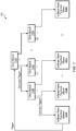
- Fig. 7 shows a block diagram illustrating one embodiment of a clock and trigger distribution system 700.
- system 700 includes clock modules 710A-N which are configured to provide clock and trigger signals to SRPs 400A-N.
- the SRPs 400 include a master SRP 400A and multiple slave SRPs 400B-N.
- low skew buffering circuitry and matched-length transmission cables are used to reduce skew between the reference clock inputs and trigger inputs at each SRP.
- reference clock skew is less than 100 picoseconds and trigger skew is less than 1.5 nanoseconds.
- Clock modules 710 are arranged in a hierarchical tree structure with clock module 710A at the root.
- Each clock module 710 in the illustrated embodiment, is configured to receive or generate a clock signal and a trigger signal and provide the clock signal and the trigger signal to multiple other elements.
- This configuration may allow the system 700 to be scaled to synchronize massive MIMO systems with various numbers of SRPs 400.
- the hierarchical structure may include greater or smaller numbers of levels of clock modules (e.g., 1, 3, 4, etc.).
- Master SRP 400A may trigger a sample (e.g., of uplink data) by asserting the trigger line to clock module 710A.
- the trigger may propagate through clock modules 710A to each SRP 400, which may perform various operations such as sampling based on the trigger.
- the master device also receives the trigger.
- the master device is an SRP, but in other embodiments the master device may be any appropriate processing element such as the central controller 530, etc.
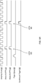
- Figs. 8A-9 illustrate exemplary timing diagrams for synchronizing an event across multiple devices according to some embodiments.
- Fig. 8A shows the reference clock 810 and a sampling clock 820 of one of the SRPs.
- a fixed relationship has been established with a reference clock 810.
- sampling clock 820 has been phase locked to the reference clock 810.
- the reference clock has a lower frequency than the sampling clock.
- sampling clock 820 is also disciplined to a particular frequency (a particular number of edges per reference clock edge).
- timing and clock distribution unit 440 includes a phase-locked loop and/or other circuitry configured to discipline an internal sampling clock to a reference clock.
- reference clock 810 is provided to the "ref in" input of each SRP 400.
- Fig. 8B-8C show alignment of common periodic time reference (CPTR) signals across multiple devices.
- each SRP 400 is configured to generate an internal CPTR and slave SRPs 400B-400N are configured to align their CPTRs (e.g., to the CPTR of master SRP 400A or to some other point). Assuming that each device has locked its sampling clock to the same reference clock, alignment of the CPTRs may ensure that the CPTRs occur at the same sampling clock edge across all devices.
- the CPTR is a 10 MHz signal.
- the CPTR is high for one sample clock cycle and then low for the remainder of its period. In other embodiments, any of various appropriate waveforms may be used for CPTRs.
- the CPTR period is configurable. In various embodiments, the CPTR period is configured to be longer than propagation delay in a synchronization system such as system 700.
- one or more of SRPs 400 are configured to utilize a clock signal at twice the frequency of sampling clock 820 and double data rate (DDR) flip flop circuitry to determine how many edges of sampling clock 820 to move each device's CPTR in order to align the CPTRs to the same sampling clock edge.
- DDR double data rate
- a start pulse is sent to each device and each device is configured to measure the difference between receipt of the start pulse and its CPTR. In some embodiments, this information is sent to central controller 530 or one of the SRPs 400, which is configured to determine how far each CPTR should be moved for alignment.
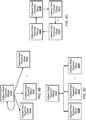
- Fig. 9A shows an exemplary use of CPTRs to synchronize an event.
- devices A and B have disciplined their sampling clocks based on a reference clock and aligned their CPTRs.
- a trigger signal 950 is received (e.g., at the master device) and transmitted to the synchronization system (e.g., to clock module 710A and throughout the tree) on the next CPTR edge (CPTR 970).
- the CPTR 970 CPTR 970
- each device is configured to perform an operation (e.g., a sampling operation) on the subsequent CPTR 980 (illustrated by the synchronized trigger 960).
- the triggering device is configured to record the delay between receiving the trigger and transmitting the trigger signal and/or the delay between receiving the trigger and the synchronized trigger.
- the latter delay is between one and two CPTR periods. In embodiments in which the CPTR is longer than the propagation delay, this may ensure that all the synchronized devices can perform the event on the same sampling clock edge, even in systems in which the devices would not have received the trigger signal 950 on the same sampling clock edge. Said another way, slowing down the rate at which triggers are evaluated (using the CPTR, which is slower than the sampling clocks), repeatability is improved at the expense of some trigger latency.
- the illustrated synchronization may be performed across multiple processing elements, e.g., multiple SRPs or FPGAs.
- Fig. 7 shows a hierarchical structure
- Fig. 9B shows an exemplary star network in which the master SRP 400A is configured to transmit trigger signals to each slave (and to itself in some embodiments).
- system 700 is one example of a star network with a hierarchical set of clock modules 710 used to transmit the triggers to the slave SRPs 400B-N.
- Fig. 9C shows an exemplary bus topology in which the master SRP 400A is configured to transmit trigger signals to each slave (and to itself in some embodiments) via a bus.
- Fig. 9B shows an exemplary star network in which the master SRP 400A is configured to transmit trigger signals to each slave (and to itself in some embodiments) via a bus.
- FIGD shows an exemplary ring topology in which a trigger from the master SRP 400A is forwarded along a ring of slave SRPs 400B-N (e.g., via the trigger out ports shown in Fig. 4 ).
- the reference clock signal is also distributed via the ring topology.
- various other network topologies such as daisy chain couplings may be implemented.
- each SRP 400 may be configured to maintain a local time and to reset or update the local time based on a trigger signal from a master device.
- a pulse-per-second (PPS) signal is transmitted to each SRP 400 and a command is issued to each radio to set a common time on the next edge of the PPS signal, to establish a common time.
- the shared time may be set to an arbitrary time or a reference time, e.g., a coordinated universal time (UTC) queried from a GPS.
- UTC coordinated universal time
- commands may be issued to the SRPs 400 to perform future actions at a particular time.
- trigger-based synchronization may be preferable to time-based synchronization, e.g., because of greater calibration time for time-based synchronization and latency in loading a future event, which may render immediate triggering events difficult to accomplish.
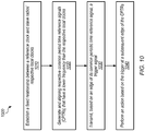
- Fig. 10 shows a flow diagram illustrating one exemplary embodiment of a method 1000 for synchronization of radio circuitry.
- the method shown in Fig. 10 may be used in conjunction with any of the computer systems, devices, elements, or components disclosed herein, among other devices. In various embodiments, some of the method elements shown may be performed concurrently, in a different order than shown, or may be omitted. Additional method elements may also be performed as desired.
- Flow begins at 1010.
- a fixed relationship is established between a reference clock and slave radios' respective local clocks.
- the fixed relationship may be a frequency and/or phase relationship.
- the reference clock is at a lower frequency than the local clocks.
- the reference clock is transmitted via a clock and trigger distribution network.
- the clock and trigger distribution network is a hierarchical tree.
- a master device and the slave radios generate and align respective common periodic time reference signals (CPTRs) that have a lower frequency than the respective local clocks.
- the master device is also a radio and is configured or specified as a master device rather than a slave device.
- assignment of one of the radios to be the master device is configurable by a user and/or by the system (e.g., based on current operating conditions).
- each device is configured to measure a number of local clock edges (or a number of edges of a derivation of the local clock, e.g., a 2x or greater clock) from a start signal and provide the measured information to central controller 530 and/or to the master device.
- the master device is configured to instruct each device how many clock cycles to move its respective CPTR to achieve alignment.
- the master device transmits, based on an edge of its common periodic time reference signal, a trigger signal.
- the master device is configured to wait until its next CPTR edge to send the trigger. This may ensure that all devices can trigger on the same CPTR edge, e.g., by giving a full CPTR period for the trigger signal from the master to propagate. Otherwise, if the master were to send a trigger signal just before a CPTR edge, different slave devices might receive the signal in different CPTR periods, e.g., based on slightly different propagation delays, etc.
- the master device transmits the trigger signal via the clock and trigger distribution network.
- the slave radios perform an action based on the trigger at a subsequent edge (subsequent to the edge on which the master device sends the trigger signal) of their respective CPTRs.
- the action is synchronized.
- the action is a sampling action for signals in a massive MIMO base station.
- the master device is configured to receive or generate a trigger indication and wait until the edge of its CPTR to transmit the trigger signal.
- the action is a sampling action.
- the fixed relationship includes discipline to a particular frequency and/or a phase lock.
- the reference clock has a lower frequency than the local clocks.
- a period of the CPTRs is configured to be greater than a propagation delay of the clock and trigger distribution system.
- the disclosed system is configured to utilize conventional signaling (e.g., 3GPP LTE signaling).
- conventional signaling e.g., 3GPP LTE signaling
- the LTE frame structure is modified or a different frame structure is used to improve massive MIMO processing, especially in the reciprocity-based systems.
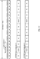
- Fig. 11 shows an exemplary LTE time division duplexing (TDD) frame.
- the frame covers ten milliseconds (ms) in the time dimension and includes ten subframes, each covering one ms.
- each subframe is used either for downlink (DL) data, as a guard subframe, or for uplink (UL) data.
- LTE TDD defines several frame configurations, two of which are shown in Fig. 11 .
- the guard frames may include pilot time slots such as DwPTS and UpPTS.
- the LTE frame structure is problematic for reciprocity-based MIMO.
- the following events must occur within the coherence time of the channel: process received samples, measure uplink channels, and precode downlink samples.
- the turnaround time between receiving an uplink pilot symbol to transmitting a downlink symbol is specified to be less than 0.5 ms to ensure that it is less than the coherence-time, even for UEs that are moving relatively quickly. As shown in Fig. 11 , this is not typically achieved using a typical LTE TDD frame, because a full 1 ms subframe is dedicated to UL or DL data.
- Fig. 12 shows an exemplary data frame according to some embodiments.
- each frame covers ten ms and includes ten subframes which each cover one ms in the time dimension.
- each subframe (and each slot) includes both uplink and downlink data, as well as a switch guard symbol.
- each slot (corresponding to half of a subframe) includes 7 OFDM symbols, one of which is used for an uplink pilot symbol, two of which are used for uplink data, two of which are used for downlink data, and two of which are used as guard symbols for switching between uplink and downlink.
- the uplink pilot symbol and switch guard periods each consist of a single OFDM symbol.
- uplink pilot symbols are sequentially interleaved in the frequency dimension for users in the system. For example, each user's pilot data may be distributed across multiple separate subcarrier chunks.
- pre-coded pilot information is also inserted into DL OFDM symbols to allow for compensation of RF chain responses.
- each frame starts with a down-link broadcasting subframe to set up initial network synchronization (e.g., for mobile devices 106 to synchronize carrier and/or sampling frequency with the base station).
- initial network synchronization e.g., for mobile devices 106 to synchronize carrier and/or sampling frequency with the base station.
- the remaining nine subframes are used for UL and DL data transmission.
- the turnaround time between receiving an uplink pilot symbol and transmitting the last downlink data that is encoded based on the uplink pilot symbol is less than 0.5 ms. In some embodiments, the turnaround time between receiving an uplink pilot symbol and transmitting the last downlink data that is encoded based on the uplink pilot symbol is less than the coherence time of the channel, which may vary over time, e.g., based on movement of source or receiver.
- the "coherence time" of a channel quantifies the similarity of the channel response at different times and refers to a time interval over which the impulse response to the channel is considered to be not varying.
- Coherence time is inversely proportional to doppler spread and is often estimated using the equation 0.423 times the maximum doppler frequency (e.g., as determined based on movement of the source and/or receiver).
- the maximum doppler frequency of a transmitter moving directly towards a receiver is the frequency of the carrier wave times the velocity of movement divided by the speed of light.
- frame structures with short turnaround between uplink pilot receipt and downlink data transmission allow reciprocity to be used reliably even for fast-moving mobile devices 106.
- the distributed processing techniques disclosed herein may provide a short critical path for signals and processing needed to meet such a short turnaround time.
- time dimension duplexing (TDD) techniques may be advantageous relative to frequency division duplexing (FDD) techniques because FDD systems may run out of unique pilot tones for a receiver to effectively resolve channel conditions, given the large number of antennas.
- Fig. 13 shows a flow diagram illustrating one exemplary embodiment of a method 1300 for synchronization of radio circuitry.
- the method shown in Fig. 13 may be used in conjunction with any of the computer systems, devices, elements, or components disclosed herein, among other devices. In various embodiments, some of the method elements shown may be performed concurrently, in a different order than shown, or may be omitted. Additional method elements may also be performed as desired.
- Flow begins at 1310.
- an uplink pilot symbol is received from a mobile device over a first channel.
- pilot symbols are allocated to users in an interleaved manner.
- the first channel is a wireless channel.
- uplink data is received from the mobile device over the first channel.
- the uplink data is included in one or more orthogonal frequency-division multiplexing (OFDM) symbols.
- OFDM orthogonal frequency-division multiplexing
- channel information is determined based on the pilot symbol.
- MIMO detector 340, channel estimator 330, and/or link quality evaluator 350 are configured to determine this information within a single OFDM symbol, allowing greater time to performing downlink processing.
- pilot information in a given OFDM symbol is processed by multiple MIMO detectors and/or channel estimators 330 in system 340.
- pilot information for a given user is processed by multiple different processing elements.
- downlink data is precoded based on the channel information.
- multiple MIMO precoders 345 are configured to perform this encoding and transmit their frequency portions to a bandwidth combiner 325.
- the precoded downlink data is transmitted to the mobile device. This transmission may be performed within the coherence time for a receiving device, allowing reciprocity-based precoding even for fast-moving devices. Further, it may allow precoding to be performed in the massive MIMO context with large numbers of antennas and user devices.
- a guard period between reception of the uplink data and transmission of the downlink data is only one OFDM symbol.
- the transition time is less than one millisecond, which may be advantageous relative to the slower turnaround time for LTE TDD frames.
- an interval between receiving the uplink pilot symbol and transmitting a final symbol of the precoded downlink data (the last symbol precoded based on the particular uplink pilot symbol) is less than a coherence time of the first channel.
- the short turnaround time is achieved by separately decoding and/or precoding different time and/or frequency portions of uplink and/or downlink data and/or pilots (e.g., as discussed above with reference to Fig. 3 ).
- base station 102 is configured to transmit a signaling schedule that specifies transmission intervals for the uplink pilot symbol, the uplink data, and the downlink data. User device may then communicate with base station 102 based on the signaling schedule. In some embodiments, base station 102 is configured to determine the channel information based on the pilot symbol within a time interval corresponding to a single OFDM symbol at the symbol rate.
- the disclosed massive MIMO system may have the following attributes: flexible software defined radios (SDRs) for acquiring and transmitting radio frequency (RF) signals, accurate time and frequency synchronization across the radio heads, high-throughput deterministic bus for moving and aggregating large amounts of data, and high-performance processing to meet real-time performance requirements.
- SDRs flexible software defined radios
- RF radio frequency
- the system may also be quickly customized for a wide variety of operating conditions and/or research needs.
Landscapes
- Engineering & Computer Science (AREA)
- Signal Processing (AREA)
- Computer Networks & Wireless Communication (AREA)
- Radio Transmission System (AREA)
- Mobile Radio Communication Systems (AREA)
Claims (15)
- Une station de base (12, 300) comprenant :une pluralité d'antennes ;une pluralité d'éléments de traitement (310, 320, 330, 340) couplés à la pluralité d'antennes et configurés pour effectuer un traitement pour des communications sans fil via la pluralité d'antennes ;une interconnexion configurée pour coupler la pluralité d'éléments de traitement ;où la station de base est configurée pour combiner des signaux reçus par des antennes multiples ;où, pour au moins un sous-ensemble des éléments de traitement (340), chaque élément de traitement est configuré pour opérer sur une partie différente des signaux combinés, chaque partie comprenant des signaux provenant d'antennes multiples ; etcaractérisée en ce que la station de base est configurée pour ajuster dynamiquement le nombre d'éléments de traitement du sous-ensemble d'éléments de traitement configurés pour opérer sur des parties différentes des signaux combinés et la station de base étant configurée pour ajuster dynamiquement la taille des parties différentes des signaux combinés sur lesquels opère chaque élément de traitement du sous-ensemble des éléments de traitement.
- La station de base de la revendication 1,
dans laquelle, pour le au moins un sous-ensemble des éléments de traitement, chaque élément de traitement est configuré pour opérer sur une partie de fréquence différente des signaux reçus par des antennes multiples. - La station de base de la revendication 1,
dans laquelle, pour le au moins un sous-ensemble des éléments de traitement, chaque élément de traitement est configuré pour opérer sur une partie temporelle différente des signaux reçus par des antennes multiples. - La station de base de la revendication 1,
dans laquelle au moins l'un de la pluralité d'éléments de traitement (310) est configuré pour combiner des signaux provenant d'antennes multiples pour générer un signal combiné destiné à être traité ;
dans laquelle au moins l'un de la pluralité d'éléments de traitement (320) est configuré pour fractionner des signaux provenant du signal combiné en parties destinées à être traitées. - La station de base de la revendication 1, dans laquelle, pour le au moins un sous-ensemble des éléments de traitement, chaque élément de traitement est configuré pour opérer sur les parties différentes du signal combiné par détection d'un ou plusieurs symboles pilotes de liaison montante et génération d'une information de canal sur la base des un ou plusieurs symboles pilotes de liaison montante.
- La station de base de la revendication 5, dans laquelle la station de base est configurée pour configurer des signaux d'émission via des antennes multiples sur la base de l'information de canal.
- La station de base de la revendication 6, dans laquelle la station de base est configurée pour précoder des parties différentes des signaux à émettre en utilisant au moins un sous-ensemble des éléments de traitement (345), et dans laquelle la station de base est configurée pour combiner les parties différentes puis fractionner les parties combinées pour émission via des antennes multiples.
- Un procédé comprenant :la réception de signaux sans fil via une pluralité d'antennes ;la délivrance de parties différentes des signaux combinés à des éléments de traitement multiples différents pour traitement en parallèle ;l'émission, via la pluralité d'antennes, de signaux qui sont générés sur la base du traitement des parties des signaux combinés par la pluralité d'éléments de traitement ; etcaractérisé par l'ajustement dynamique du nombre des éléments de traitement multiples différents et de la taille des parties différentes des signaux combinés délivrés à chacun des éléments de traitement multiples différents.
- Le procédé de la revendication 8, dans lequel les parties des signaux combinés correspondent à des bandes de fréquences différentes.
- Le procédé de la revendication 8, dans lequel les parties des signaux combinés correspondent à des créneaux temporels différents.
- Le procédé de la revendication 8, comprenant en outre :le précodage, en utilisant des éléments de traitement multiples différents de la pluralité d'éléments de traitement, sur la base du traitement des parties des signaux combinés, des signaux pour émission via des antennes multiples de la pluralité d'antennes, chacun des éléments de traitement multiples différents précodant une partie différente des signaux.
- Le procédé de la revendication 11, comprenant en outre :la combinaison des résultats du précodage provenant des éléments de traitement multiples différents ; etle fractionnement des résultats combinés pour émission via des antennes différentes des antennes multiples.
- Le procédé de la revendication 11, dans lequel le précodage est effectué sur la base d'estimées de canal pour des symboles pilotes de liaison montante dans les signaux sans fil reçus.
- Le procédé de la revendication 8, dans lequel les antennes multiples comprennent plus que huit antennes.
- Un programme informatique comprenant des instructions pour mettre en oeuvre un procédé selon l'une des revendications 8 à 14.
Applications Claiming Priority (6)
| Application Number | Priority Date | Filing Date | Title |
|---|---|---|---|
| US201461989784P | 2014-05-07 | 2014-05-07 | |
| US201462024896P | 2014-07-15 | 2014-07-15 | |
| US201462024872P | 2014-07-15 | 2014-07-15 | |
| US201462024885P | 2014-07-15 | 2014-07-15 | |
| US14/703,214 US10855346B2 (en) | 2014-05-07 | 2015-05-04 | Massive MIMO architecture |
| PCT/US2015/029550 WO2015171824A1 (fr) | 2014-05-07 | 2015-05-06 | Architecture mimo massive |
Publications (2)
| Publication Number | Publication Date |
|---|---|
| EP3140918A1 EP3140918A1 (fr) | 2017-03-15 |
| EP3140918B1 true EP3140918B1 (fr) | 2017-08-30 |
Family
ID=54368737
Family Applications (3)
| Application Number | Title | Priority Date | Filing Date |
|---|---|---|---|
| EP15723405.5A Active EP3140918B1 (fr) | 2014-05-07 | 2015-05-06 | Architecture mimo massive |
| EP15723808.0A Active EP3140919B1 (fr) | 2014-05-07 | 2015-05-07 | Signalisation et structure de trame de systèmes de télécommunication cellulaire à mimo en masse |
| EP15727489.5A Active EP3140920B1 (fr) | 2014-05-07 | 2015-05-07 | Synchronisation de systèmes à grand nombre d'antennes |
Family Applications After (2)
| Application Number | Title | Priority Date | Filing Date |
|---|---|---|---|
| EP15723808.0A Active EP3140919B1 (fr) | 2014-05-07 | 2015-05-07 | Signalisation et structure de trame de systèmes de télécommunication cellulaire à mimo en masse |
| EP15727489.5A Active EP3140920B1 (fr) | 2014-05-07 | 2015-05-07 | Synchronisation de systèmes à grand nombre d'antennes |
Country Status (4)
| Country | Link |
|---|---|
| US (3) | US10855346B2 (fr) |
| EP (3) | EP3140918B1 (fr) |
| CN (3) | CN106464324B (fr) |
| WO (3) | WO2015171824A1 (fr) |
Families Citing this family (39)
| Publication number | Priority date | Publication date | Assignee | Title |
|---|---|---|---|---|
| CN105245310B (zh) * | 2014-07-09 | 2020-01-14 | 中兴通讯股份有限公司 | 一种下行导频信号的处理方法及系统 |
| US10342012B2 (en) | 2015-03-15 | 2019-07-02 | Qualcomm Incorporated | Self-contained time division duplex (TDD) subframe structure |
| US10075970B2 (en) | 2015-03-15 | 2018-09-11 | Qualcomm Incorporated | Mission critical data support in self-contained time division duplex (TDD) subframe structure |
| US9936519B2 (en) | 2015-03-15 | 2018-04-03 | Qualcomm Incorporated | Self-contained time division duplex (TDD) subframe structure for wireless communications |
| US9814058B2 (en) | 2015-05-15 | 2017-11-07 | Qualcomm Incorporated | Scaled symbols for a self-contained time division duplex (TDD) subframe structure |
| US9992790B2 (en) | 2015-07-20 | 2018-06-05 | Qualcomm Incorporated | Time division duplex (TDD) subframe structure supporting single and multiple interlace modes |
| US9553640B1 (en) * | 2015-12-22 | 2017-01-24 | Microsoft Technology Licensing, Llc | Using multi-feed antennas |
| US10236958B2 (en) * | 2016-03-21 | 2019-03-19 | University Of Science And Technology Of China | Method for signal transmission to multiple user equipments utilizing reciprocity of wireless channel |
| US10243715B2 (en) | 2016-04-01 | 2019-03-26 | National Instruments Corporation | Unified flexible radio access technology (RAT) for 5G mobile communication systems |
| US10103928B2 (en) | 2016-05-23 | 2018-10-16 | National Instruments Corporation | Nyquist and square root nyquist filters for pulse shaping in wireless communications |
| US10257005B2 (en) | 2016-08-11 | 2019-04-09 | National Instruments Corporation | Radio frequency (RF) communication systems using RF switching guard periods to transmit special symbols in block symbol transmissions |
| US9991938B2 (en) | 2016-08-11 | 2018-06-05 | National Instruments Corporation | Intra-node channel reciprocity compensation for radio access in MIMO wireless communication systems |
| US10277734B2 (en) | 2016-08-22 | 2019-04-30 | National Instruments Corporation | Methods and systems for eSIM programming of cellular devices |
| US10201020B2 (en) | 2016-09-19 | 2019-02-05 | National Instruments Corporation | Multi-user random access procedures for massive MIMO wireless communication systems |
| US10396867B2 (en) * | 2016-11-03 | 2019-08-27 | National Instruments Corporation | Reduced-complexity downlink (DL) signal demodulation using reciprocity reference signals for MIMO wireless communication systems |
| US10447513B2 (en) | 2017-01-06 | 2019-10-15 | National Instruments Corporation | Common phase error (CPE) compensation for frequency division multiplex (FDM) symbols in wireless communication systems |
| US11509364B2 (en) | 2017-03-13 | 2022-11-22 | Qualcomm Incorporated | Techniques and apparatuses for uplink precoder determination using downlink reference signals or downlink precoder determination using uplink reference signals |
| CN110771078B (zh) | 2017-04-03 | 2022-04-15 | 美国国家仪器有限公司 | 测量基于ptrs端口选择的无线通信系统 |
| AU2018263932B2 (en) * | 2017-05-03 | 2021-06-03 | Assia Spe, Llc | Systems and methods for implementing high-speed waveguide transmission over wires |
| US12267123B2 (en) | 2017-05-03 | 2025-04-01 | Assia Spe, Llc | Systems and methods for implementing high-speed waveguide transmission over wires |
| WO2018204571A1 (fr) | 2017-05-05 | 2018-11-08 | National Instruments Corporation | Système de communication sans fil qui effectue un rapport de faisceau sur la base d'une combinaison de mesures d'informations de puissance de réception de signal de référence et d'état de canal |
| US10153814B1 (en) | 2017-06-13 | 2018-12-11 | Corning Incorporated | Massive multiple-input multiple-output (M-MIMO) wireless distribution system (WDS) and related methods for optimizing the M-MIMO WDS |
| US10312978B2 (en) | 2017-07-18 | 2019-06-04 | National Instruments Corporation | Wireless transceiver station with performs multi-path reciprocity calibration with multiple reference antennas |
| US10567065B2 (en) | 2017-08-11 | 2020-02-18 | National Instruments Corporation | Radio frequency beam management and failure pre-emption |
| JP2019083427A (ja) * | 2017-10-31 | 2019-05-30 | 株式会社日立製作所 | 無線通信システムおよび無線監視制御システム |
| KR102349455B1 (ko) | 2018-01-19 | 2022-01-10 | 삼성전자주식회사 | 무선통신시스템에서 신호를 송수신하는 방법 및 장치 |
| US10218548B1 (en) | 2018-01-24 | 2019-02-26 | National Instruments Corporation | Wireless radio receiver that performs adaptive phase tracking |
| US10218549B1 (en) | 2018-01-24 | 2019-02-26 | National Instruments Corporation | Wireless radio receiver that performs adaptive phase tracking |
| JP6959531B2 (ja) * | 2018-04-16 | 2021-11-02 | 日本電信電話株式会社 | 無線通信方法、制御装置及び無線通信システム |
| US11050496B2 (en) * | 2018-05-21 | 2021-06-29 | National Instruments Corporation | Over-the-air testing of millimeter wave integrated circuits with integrated antennas |
| CN108833060B (zh) * | 2018-09-17 | 2020-09-11 | 东南大学 | 一种基于ep-nsa算法的大规模mimo系统检测方法 |
| US10908254B2 (en) * | 2018-12-20 | 2021-02-02 | GM Global Technology Operations LLC | Traveling-wave imaging manifold for high resolution radar system |
| KR102756567B1 (ko) * | 2019-06-27 | 2025-01-20 | 삼성전자주식회사 | 프리코딩을 수행하는 전자 장치 및 그 동작 방법 |
| US10841136B1 (en) | 2019-08-14 | 2020-11-17 | National Instruments Corporation | Asymmetric factorization of generalized raised cosine filters for improved selectivity |
| US11716123B2 (en) | 2019-10-09 | 2023-08-01 | The Trustees Of Columbia University In The City Of New York | Systems, methods, and media for recovering data symbols in multiple-input, multiple-output receivers |
| CN111210612B (zh) * | 2019-10-29 | 2021-01-19 | 浙江浙大中控信息技术有限公司 | 基于公交gps数据与站点信息提取公交线路轨迹的方法 |
| CN117811687A (zh) * | 2022-09-26 | 2024-04-02 | 施耐德电器工业公司 | 用于多个操作系统时间同步的系统与方法 |
| KR20240082813A (ko) * | 2022-12-02 | 2024-06-11 | 휴림네트웍스 주식회사 | 시분할 듀플렉스 방식의 반능동 기지국 안테나 시스템 |
| CN119172205B (zh) * | 2024-08-05 | 2025-11-07 | 南京大学 | 适用于FDD Massive MIMO系统的自适应导频发送方法 |
Family Cites Families (24)
| Publication number | Priority date | Publication date | Assignee | Title |
|---|---|---|---|---|
| US9893774B2 (en) * | 2001-04-26 | 2018-02-13 | Genghiscomm Holdings, LLC | Cloud radio access network |
| US20070025399A1 (en) * | 2002-01-24 | 2007-02-01 | Radioframe Networks, Inc. | Method and apparatus for frequency and timing distribution through a packet-based network |
| US8208364B2 (en) * | 2002-10-25 | 2012-06-26 | Qualcomm Incorporated | MIMO system with multiple spatial multiplexing modes |
| US7986742B2 (en) | 2002-10-25 | 2011-07-26 | Qualcomm Incorporated | Pilots for MIMO communication system |
| US7580444B2 (en) * | 2004-05-04 | 2009-08-25 | Her Majesty The Queen In Right Of Canada, As Represented By The Minister Of Industry, Through The Communications Research Centre Canada | Frequency hopping communication system |
| CN1949691B (zh) * | 2006-09-28 | 2011-08-31 | 哈尔滨工业大学 | 一种mimo信道模拟器的控制方法及其实现装置 |
| US7702029B2 (en) * | 2006-10-02 | 2010-04-20 | Freescale Semiconductor, Inc. | MIMO precoding enabling spatial multiplexing, power allocation and adaptive modulation and coding |
| KR101631784B1 (ko) * | 2007-01-12 | 2016-06-17 | 텔레폰악티에볼라겟엘엠에릭슨(펍) | 무선 통신 시스템에서의 방법 및 장치 |
| US8503375B2 (en) * | 2007-08-13 | 2013-08-06 | Qualcomm Incorporated | Coding and multiplexing of control information in a wireless communication system |
| US9154273B2 (en) * | 2008-12-22 | 2015-10-06 | Lg Electronics Inc. | Method and apparatus for data transmission using a data frame |
| JP5282618B2 (ja) | 2009-03-24 | 2013-09-04 | 富士通株式会社 | 無線基地局装置及びその同期方法 |
| CN101854186B (zh) * | 2009-03-30 | 2015-04-01 | 三星电子株式会社 | 用于数据传输的预编/解码方法和系统 |
| US8638138B2 (en) * | 2009-09-14 | 2014-01-28 | Achronix Semiconductor Corporation | Hierarchical global clock tree |
| US8819161B1 (en) * | 2010-01-18 | 2014-08-26 | Marvell International Ltd. | Auto-syntonization and time-of-day synchronization for master-slave physical layer devices |
| US8599861B2 (en) | 2010-06-03 | 2013-12-03 | Kathrein-Werke Kg | Active antenna array and method for relaying radio signals |
| US8570103B2 (en) * | 2011-06-16 | 2013-10-29 | Donald C. D. Chang | Flexible multi-channel amplifiers via wavefront muxing techniques |
| US9241333B2 (en) * | 2011-01-13 | 2016-01-19 | Telefonaktiebolaget L M Ericsson (Publ) | Modular base station |
| US8654687B2 (en) * | 2011-05-17 | 2014-02-18 | Telefonaktiebolaget L M Ericsson (Publ) | Dual channel time division duplex (TDD) communication |
| CN102404006A (zh) * | 2011-10-27 | 2012-04-04 | 天津大学 | 面向4g光载无线通信的频率综合电路 |
| US8799853B2 (en) | 2012-02-17 | 2014-08-05 | National Instruments Corporation | Dynamic synchronization in a target system having multiple programmable hardware elements |
| US9184806B2 (en) | 2012-03-07 | 2015-11-10 | Lg Electronics Inc. | Method for performing hierarchical beamforming in wireless access system and device therefor |
| CN102916735B (zh) * | 2012-10-17 | 2016-06-08 | 东南大学 | 利用大规模天线阵列的无线通信方法 |
| EP3664573B1 (fr) * | 2013-02-11 | 2025-06-11 | Outdoor Wireless Networks LLC | Unité pour système d'antenne distribués |
| CN103546264B (zh) * | 2013-11-13 | 2017-07-28 | 东南大学 | 基于导频复用的大规模mimo无线通信方法 |
-
2015
- 2015-05-04 US US14/703,214 patent/US10855346B2/en active Active
- 2015-05-04 US US14/703,262 patent/US9577729B2/en active Active
- 2015-05-04 US US14/703,293 patent/US9985701B2/en active Active
- 2015-05-06 EP EP15723405.5A patent/EP3140918B1/fr active Active
- 2015-05-06 CN CN201580032055.3A patent/CN106464324B/zh active Active
- 2015-05-06 WO PCT/US2015/029550 patent/WO2015171824A1/fr not_active Ceased
- 2015-05-07 CN CN201580023704.3A patent/CN106465316B/zh active Active
- 2015-05-07 EP EP15723808.0A patent/EP3140919B1/fr active Active
- 2015-05-07 CN CN201580023037.9A patent/CN106464317B/zh active Active
- 2015-05-07 WO PCT/US2015/029786 patent/WO2015171956A1/fr not_active Ceased
- 2015-05-07 WO PCT/US2015/029788 patent/WO2015171958A1/fr not_active Ceased
- 2015-05-07 EP EP15727489.5A patent/EP3140920B1/fr active Active
Non-Patent Citations (1)
| Title |
|---|
| None * |
Also Published As
| Publication number | Publication date |
|---|---|
| US9577729B2 (en) | 2017-02-21 |
| EP3140919A1 (fr) | 2017-03-15 |
| US20150326286A1 (en) | 2015-11-12 |
| CN106465316A (zh) | 2017-02-22 |
| CN106464324A (zh) | 2017-02-22 |
| EP3140920B1 (fr) | 2017-11-29 |
| WO2015171824A1 (fr) | 2015-11-12 |
| CN106465316B (zh) | 2020-01-21 |
| EP3140919B1 (fr) | 2017-09-13 |
| CN106464317B (zh) | 2020-08-25 |
| CN106464317A (zh) | 2017-02-22 |
| EP3140918A1 (fr) | 2017-03-15 |
| US20150326383A1 (en) | 2015-11-12 |
| US9985701B2 (en) | 2018-05-29 |
| US10855346B2 (en) | 2020-12-01 |
| US20150326291A1 (en) | 2015-11-12 |
| CN106464324B (zh) | 2019-12-06 |
| WO2015171958A1 (fr) | 2015-11-12 |
| WO2015171956A1 (fr) | 2015-11-12 |
| EP3140920A1 (fr) | 2017-03-15 |
Similar Documents
| Publication | Publication Date | Title |
|---|---|---|
| EP3140918B1 (fr) | Architecture mimo massive | |
| US10243715B2 (en) | Unified flexible radio access technology (RAT) for 5G mobile communication systems | |
| CN116326022B (zh) | 新空口覆盖范围限制增强的信道估计 | |
| US9654188B2 (en) | Scalable massive MIMO | |
| Lacruz et al. | A real-time experimentation platform for sub-6 GHz and millimeter-wave MIMO systems | |
| US10396867B2 (en) | Reduced-complexity downlink (DL) signal demodulation using reciprocity reference signals for MIMO wireless communication systems | |
| US12015506B2 (en) | Base station signaling for enhanced channel estimation for new radio coverage | |
| CN116458077B (zh) | 用于估计老化无线信道的基于小波变换的跟踪 | |
| Dai et al. | A scalable generator for massive MIMO baseband processing systems with beamspace channel estimation | |
| US11575419B2 (en) | Method and apparatus for sending signal, method and apparatus for reporting channel state information, and storage medium | |
| CN115968536A (zh) | 测试无线电设备 | |
| KR102955350B1 (ko) | 뉴 라디오 커버리지에 대한 향상된 채널 추정을 위한 기지국 시그널링 | |
| CN119544162A (zh) | 一种通信方法及相关设备 | |
| CN120223147A (zh) | 卫星通信方法及装置 | |
| CN120050695A (zh) | 通信方法及相关设备 |
Legal Events
| Date | Code | Title | Description |
|---|---|---|---|
| PUAI | Public reference made under article 153(3) epc to a published international application that has entered the european phase |
Free format text: ORIGINAL CODE: 0009012 |
|
| REG | Reference to a national code |
Ref country code: DE Ref legal event code: R079 Ref document number: 602015004473 Country of ref document: DE Free format text: PREVIOUS MAIN CLASS: H04B0007040000 Ipc: H04B0007041300 |
|
| 17P | Request for examination filed |
Effective date: 20161201 |
|
| AK | Designated contracting states |
Kind code of ref document: A1 Designated state(s): AL AT BE BG CH CY CZ DE DK EE ES FI FR GB GR HR HU IE IS IT LI LT LU LV MC MK MT NL NO PL PT RO RS SE SI SK SM TR |
|
| AX | Request for extension of the european patent |
Extension state: BA ME |
|
| GRAP | Despatch of communication of intention to grant a patent |
Free format text: ORIGINAL CODE: EPIDOSNIGR1 |
|
| RIC1 | Information provided on ipc code assigned before grant |
Ipc: H04W 56/00 20090101ALI20170302BHEP Ipc: H04B 7/0413 20170101AFI20170302BHEP |
|
| DAV | Request for validation of the european patent (deleted) | ||
| DAX | Request for extension of the european patent (deleted) | ||
| INTG | Intention to grant announced |
Effective date: 20170322 |
|
| GRAS | Grant fee paid |
Free format text: ORIGINAL CODE: EPIDOSNIGR3 |
|
| GRAA | (expected) grant |
Free format text: ORIGINAL CODE: 0009210 |
|
| AK | Designated contracting states |
Kind code of ref document: B1 Designated state(s): AL AT BE BG CH CY CZ DE DK EE ES FI FR GB GR HR HU IE IS IT LI LT LU LV MC MK MT NL NO PL PT RO RS SE SI SK SM TR |
|
| REG | Reference to a national code |
Ref country code: GB Ref legal event code: FG4D |
|
| REG | Reference to a national code |
Ref country code: CH Ref legal event code: EP |
|
| REG | Reference to a national code |
Ref country code: AT Ref legal event code: REF Ref document number: 924554 Country of ref document: AT Kind code of ref document: T Effective date: 20170915 |
|
| REG | Reference to a national code |
Ref country code: IE Ref legal event code: FG4D |
|
| REG | Reference to a national code |
Ref country code: DE Ref legal event code: R096 Ref document number: 602015004473 Country of ref document: DE |
|
| REG | Reference to a national code |
Ref country code: NL Ref legal event code: MP Effective date: 20170830 |
|
| REG | Reference to a national code |
Ref country code: LT Ref legal event code: MG4D |
|
| REG | Reference to a national code |
Ref country code: AT Ref legal event code: MK05 Ref document number: 924554 Country of ref document: AT Kind code of ref document: T Effective date: 20170830 |
|
| PG25 | Lapsed in a contracting state [announced via postgrant information from national office to epo] |
Ref country code: LT Free format text: LAPSE BECAUSE OF FAILURE TO SUBMIT A TRANSLATION OF THE DESCRIPTION OR TO PAY THE FEE WITHIN THE PRESCRIBED TIME-LIMIT Effective date: 20170830 Ref country code: HR Free format text: LAPSE BECAUSE OF FAILURE TO SUBMIT A TRANSLATION OF THE DESCRIPTION OR TO PAY THE FEE WITHIN THE PRESCRIBED TIME-LIMIT Effective date: 20170830 Ref country code: NO Free format text: LAPSE BECAUSE OF FAILURE TO SUBMIT A TRANSLATION OF THE DESCRIPTION OR TO PAY THE FEE WITHIN THE PRESCRIBED TIME-LIMIT Effective date: 20171130 Ref country code: AT Free format text: LAPSE BECAUSE OF FAILURE TO SUBMIT A TRANSLATION OF THE DESCRIPTION OR TO PAY THE FEE WITHIN THE PRESCRIBED TIME-LIMIT Effective date: 20170830 Ref country code: FI Free format text: LAPSE BECAUSE OF FAILURE TO SUBMIT A TRANSLATION OF THE DESCRIPTION OR TO PAY THE FEE WITHIN THE PRESCRIBED TIME-LIMIT Effective date: 20170830 Ref country code: SE Free format text: LAPSE BECAUSE OF FAILURE TO SUBMIT A TRANSLATION OF THE DESCRIPTION OR TO PAY THE FEE WITHIN THE PRESCRIBED TIME-LIMIT Effective date: 20170830 |
|
| PG25 | Lapsed in a contracting state [announced via postgrant information from national office to epo] |
Ref country code: LV Free format text: LAPSE BECAUSE OF FAILURE TO SUBMIT A TRANSLATION OF THE DESCRIPTION OR TO PAY THE FEE WITHIN THE PRESCRIBED TIME-LIMIT Effective date: 20170830 Ref country code: BG Free format text: LAPSE BECAUSE OF FAILURE TO SUBMIT A TRANSLATION OF THE DESCRIPTION OR TO PAY THE FEE WITHIN THE PRESCRIBED TIME-LIMIT Effective date: 20171130 Ref country code: ES Free format text: LAPSE BECAUSE OF FAILURE TO SUBMIT A TRANSLATION OF THE DESCRIPTION OR TO PAY THE FEE WITHIN THE PRESCRIBED TIME-LIMIT Effective date: 20170830 Ref country code: IS Free format text: LAPSE BECAUSE OF FAILURE TO SUBMIT A TRANSLATION OF THE DESCRIPTION OR TO PAY THE FEE WITHIN THE PRESCRIBED TIME-LIMIT Effective date: 20171230 Ref country code: GR Free format text: LAPSE BECAUSE OF FAILURE TO SUBMIT A TRANSLATION OF THE DESCRIPTION OR TO PAY THE FEE WITHIN THE PRESCRIBED TIME-LIMIT Effective date: 20171201 Ref country code: RS Free format text: LAPSE BECAUSE OF FAILURE TO SUBMIT A TRANSLATION OF THE DESCRIPTION OR TO PAY THE FEE WITHIN THE PRESCRIBED TIME-LIMIT Effective date: 20170830 |
|
| PG25 | Lapsed in a contracting state [announced via postgrant information from national office to epo] |
Ref country code: NL Free format text: LAPSE BECAUSE OF FAILURE TO SUBMIT A TRANSLATION OF THE DESCRIPTION OR TO PAY THE FEE WITHIN THE PRESCRIBED TIME-LIMIT Effective date: 20170830 |
|
| PG25 | Lapsed in a contracting state [announced via postgrant information from national office to epo] |
Ref country code: CZ Free format text: LAPSE BECAUSE OF FAILURE TO SUBMIT A TRANSLATION OF THE DESCRIPTION OR TO PAY THE FEE WITHIN THE PRESCRIBED TIME-LIMIT Effective date: 20170830 Ref country code: PL Free format text: LAPSE BECAUSE OF FAILURE TO SUBMIT A TRANSLATION OF THE DESCRIPTION OR TO PAY THE FEE WITHIN THE PRESCRIBED TIME-LIMIT Effective date: 20170830 Ref country code: DK Free format text: LAPSE BECAUSE OF FAILURE TO SUBMIT A TRANSLATION OF THE DESCRIPTION OR TO PAY THE FEE WITHIN THE PRESCRIBED TIME-LIMIT Effective date: 20170830 |
|
| REG | Reference to a national code |
Ref country code: FR Ref legal event code: PLFP Year of fee payment: 4 |
|
| PG25 | Lapsed in a contracting state [announced via postgrant information from national office to epo] |
Ref country code: SK Free format text: LAPSE BECAUSE OF FAILURE TO SUBMIT A TRANSLATION OF THE DESCRIPTION OR TO PAY THE FEE WITHIN THE PRESCRIBED TIME-LIMIT Effective date: 20170830 Ref country code: SM Free format text: LAPSE BECAUSE OF FAILURE TO SUBMIT A TRANSLATION OF THE DESCRIPTION OR TO PAY THE FEE WITHIN THE PRESCRIBED TIME-LIMIT Effective date: 20170830 Ref country code: IT Free format text: LAPSE BECAUSE OF FAILURE TO SUBMIT A TRANSLATION OF THE DESCRIPTION OR TO PAY THE FEE WITHIN THE PRESCRIBED TIME-LIMIT Effective date: 20170830 Ref country code: EE Free format text: LAPSE BECAUSE OF FAILURE TO SUBMIT A TRANSLATION OF THE DESCRIPTION OR TO PAY THE FEE WITHIN THE PRESCRIBED TIME-LIMIT Effective date: 20170830 |
|
| REG | Reference to a national code |
Ref country code: DE Ref legal event code: R097 Ref document number: 602015004473 Country of ref document: DE |
|
| PLBE | No opposition filed within time limit |
Free format text: ORIGINAL CODE: 0009261 |
|
| STAA | Information on the status of an ep patent application or granted ep patent |
Free format text: STATUS: NO OPPOSITION FILED WITHIN TIME LIMIT |
|
| 26N | No opposition filed |
Effective date: 20180531 |
|
| PG25 | Lapsed in a contracting state [announced via postgrant information from national office to epo] |
Ref country code: SI Free format text: LAPSE BECAUSE OF FAILURE TO SUBMIT A TRANSLATION OF THE DESCRIPTION OR TO PAY THE FEE WITHIN THE PRESCRIBED TIME-LIMIT Effective date: 20170830 |
|
| REG | Reference to a national code |
Ref country code: CH Ref legal event code: PL |
|
| REG | Reference to a national code |
Ref country code: BE Ref legal event code: MM Effective date: 20180531 |
|
| PG25 | Lapsed in a contracting state [announced via postgrant information from national office to epo] |
Ref country code: MC Free format text: LAPSE BECAUSE OF FAILURE TO SUBMIT A TRANSLATION OF THE DESCRIPTION OR TO PAY THE FEE WITHIN THE PRESCRIBED TIME-LIMIT Effective date: 20170830 |
|
| REG | Reference to a national code |
Ref country code: IE Ref legal event code: MM4A |
|
| PG25 | Lapsed in a contracting state [announced via postgrant information from national office to epo] |
Ref country code: CH Free format text: LAPSE BECAUSE OF NON-PAYMENT OF DUE FEES Effective date: 20180531 Ref country code: LI Free format text: LAPSE BECAUSE OF NON-PAYMENT OF DUE FEES Effective date: 20180531 |
|
| PG25 | Lapsed in a contracting state [announced via postgrant information from national office to epo] |
Ref country code: LU Free format text: LAPSE BECAUSE OF NON-PAYMENT OF DUE FEES Effective date: 20180506 |
|
| PG25 | Lapsed in a contracting state [announced via postgrant information from national office to epo] |
Ref country code: IE Free format text: LAPSE BECAUSE OF NON-PAYMENT OF DUE FEES Effective date: 20180506 |
|
| PG25 | Lapsed in a contracting state [announced via postgrant information from national office to epo] |
Ref country code: BE Free format text: LAPSE BECAUSE OF NON-PAYMENT OF DUE FEES Effective date: 20180531 |
|
| PG25 | Lapsed in a contracting state [announced via postgrant information from national office to epo] |
Ref country code: MT Free format text: LAPSE BECAUSE OF NON-PAYMENT OF DUE FEES Effective date: 20180506 |
|
| PG25 | Lapsed in a contracting state [announced via postgrant information from national office to epo] |
Ref country code: TR Free format text: LAPSE BECAUSE OF FAILURE TO SUBMIT A TRANSLATION OF THE DESCRIPTION OR TO PAY THE FEE WITHIN THE PRESCRIBED TIME-LIMIT Effective date: 20170830 |
|
| PG25 | Lapsed in a contracting state [announced via postgrant information from national office to epo] |
Ref country code: PT Free format text: LAPSE BECAUSE OF FAILURE TO SUBMIT A TRANSLATION OF THE DESCRIPTION OR TO PAY THE FEE WITHIN THE PRESCRIBED TIME-LIMIT Effective date: 20170830 |
|
| PG25 | Lapsed in a contracting state [announced via postgrant information from national office to epo] |
Ref country code: RO Free format text: LAPSE BECAUSE OF FAILURE TO SUBMIT A TRANSLATION OF THE DESCRIPTION OR TO PAY THE FEE WITHIN THE PRESCRIBED TIME-LIMIT Effective date: 20170830 Ref country code: HU Free format text: LAPSE BECAUSE OF FAILURE TO SUBMIT A TRANSLATION OF THE DESCRIPTION OR TO PAY THE FEE WITHIN THE PRESCRIBED TIME-LIMIT; INVALID AB INITIO Effective date: 20150506 Ref country code: CY Free format text: LAPSE BECAUSE OF FAILURE TO SUBMIT A TRANSLATION OF THE DESCRIPTION OR TO PAY THE FEE WITHIN THE PRESCRIBED TIME-LIMIT Effective date: 20170830 Ref country code: MK Free format text: LAPSE BECAUSE OF NON-PAYMENT OF DUE FEES Effective date: 20170830 |
|
| PG25 | Lapsed in a contracting state [announced via postgrant information from national office to epo] |
Ref country code: AL Free format text: LAPSE BECAUSE OF FAILURE TO SUBMIT A TRANSLATION OF THE DESCRIPTION OR TO PAY THE FEE WITHIN THE PRESCRIBED TIME-LIMIT Effective date: 20170830 |
|
| PGFP | Annual fee paid to national office [announced via postgrant information from national office to epo] |
Ref country code: DE Payment date: 20250423 Year of fee payment: 11 |
|
| PGFP | Annual fee paid to national office [announced via postgrant information from national office to epo] |
Ref country code: GB Payment date: 20250423 Year of fee payment: 11 |
|
| PGFP | Annual fee paid to national office [announced via postgrant information from national office to epo] |
Ref country code: FR Payment date: 20250423 Year of fee payment: 11 |