EP3140929B1 - Suppression d'interférence pour des signaux ayant la même porteuse radiofréquence et transmis au même moment - Google Patents
Suppression d'interférence pour des signaux ayant la même porteuse radiofréquence et transmis au même moment Download PDFInfo
- Publication number
- EP3140929B1 EP3140929B1 EP14891246.2A EP14891246A EP3140929B1 EP 3140929 B1 EP3140929 B1 EP 3140929B1 EP 14891246 A EP14891246 A EP 14891246A EP 3140929 B1 EP3140929 B1 EP 3140929B1
- Authority
- EP
- European Patent Office
- Prior art keywords
- signal
- wcd
- interference cancellation
- network station
- transmitted
- Prior art date
- Legal status (The legal status is an assumption and is not a legal conclusion. Google has not performed a legal analysis and makes no representation as to the accuracy of the status listed.)
- Active
Links
Images


Classifications
-
- H—ELECTRICITY
- H04—ELECTRIC COMMUNICATION TECHNIQUE
- H04J—MULTIPLEX COMMUNICATION
- H04J11/00—Orthogonal multiplex systems, e.g. using WALSH codes
- H04J11/0023—Interference mitigation or co-ordination
- H04J11/0026—Interference mitigation or co-ordination of multi-user interference
- H04J11/0036—Interference mitigation or co-ordination of multi-user interference at the receiver
- H04J11/004—Interference mitigation or co-ordination of multi-user interference at the receiver using regenerative subtractive interference cancellation
-
- H—ELECTRICITY
- H04—ELECTRIC COMMUNICATION TECHNIQUE
- H04B—TRANSMISSION
- H04B1/00—Details of transmission systems, not covered by a single one of groups H04B3/00 - H04B13/00; Details of transmission systems not characterised by the medium used for transmission
- H04B1/38—Transceivers, i.e. devices in which transmitter and receiver form a structural unit and in which at least one part is used for functions of transmitting and receiving
- H04B1/40—Circuits
- H04B1/401—Circuits for selecting or indicating operating mode
-
- H—ELECTRICITY
- H04—ELECTRIC COMMUNICATION TECHNIQUE
- H04B—TRANSMISSION
- H04B1/00—Details of transmission systems, not covered by a single one of groups H04B3/00 - H04B13/00; Details of transmission systems not characterised by the medium used for transmission
- H04B1/38—Transceivers, i.e. devices in which transmitter and receiver form a structural unit and in which at least one part is used for functions of transmitting and receiving
- H04B1/40—Circuits
- H04B1/44—Transmit/receive switching
- H04B1/48—Transmit/receive switching in circuits for connecting transmitter and receiver to a common transmission path, e.g. by energy of transmitter
-
- H—ELECTRICITY
- H04—ELECTRIC COMMUNICATION TECHNIQUE
- H04B—TRANSMISSION
- H04B1/00—Details of transmission systems, not covered by a single one of groups H04B3/00 - H04B13/00; Details of transmission systems not characterised by the medium used for transmission
- H04B1/38—Transceivers, i.e. devices in which transmitter and receiver form a structural unit and in which at least one part is used for functions of transmitting and receiving
- H04B1/40—Circuits
- H04B1/50—Circuits using different frequencies for the two directions of communication
- H04B1/52—Hybrid arrangements, i.e. arrangements for transition from single-path two-direction transmission to single-direction transmission on each of two paths or vice versa
- H04B1/525—Hybrid arrangements, i.e. arrangements for transition from single-path two-direction transmission to single-direction transmission on each of two paths or vice versa with means for reducing leakage of transmitter signal into the receiver
-
- H—ELECTRICITY
- H04—ELECTRIC COMMUNICATION TECHNIQUE
- H04B—TRANSMISSION
- H04B15/00—Suppression or limitation of noise or interference
-
- H—ELECTRICITY
- H04—ELECTRIC COMMUNICATION TECHNIQUE
- H04L—TRANSMISSION OF DIGITAL INFORMATION, e.g. TELEGRAPHIC COMMUNICATION
- H04L5/00—Arrangements affording multiple use of the transmission path
- H04L5/0001—Arrangements for dividing the transmission path
- H04L5/0003—Two-dimensional division
- H04L5/0005—Time-frequency
- H04L5/0007—Time-frequency the frequencies being orthogonal, e.g. OFDM(A) or DMT
-
- H—ELECTRICITY
- H04—ELECTRIC COMMUNICATION TECHNIQUE
- H04L—TRANSMISSION OF DIGITAL INFORMATION, e.g. TELEGRAPHIC COMMUNICATION
- H04L5/00—Arrangements affording multiple use of the transmission path
- H04L5/14—Two-way operation using the same type of signal, i.e. duplex
- H04L5/16—Half-duplex systems; Simplex/duplex switching; Transmission of break signals non-automatically inverting the direction of transmission
-
- H—ELECTRICITY
- H04—ELECTRIC COMMUNICATION TECHNIQUE
- H04W—WIRELESS COMMUNICATION NETWORKS
- H04W72/00—Local resource management
- H04W72/20—Control channels or signalling for resource management
-
- H—ELECTRICITY
- H04—ELECTRIC COMMUNICATION TECHNIQUE
- H04W—WIRELESS COMMUNICATION NETWORKS
- H04W72/00—Local resource management
- H04W72/50—Allocation or scheduling criteria for wireless resources
- H04W72/54—Allocation or scheduling criteria for wireless resources based on quality criteria
- H04W72/541—Allocation or scheduling criteria for wireless resources based on quality criteria using the level of interference
-
- H—ELECTRICITY
- H04—ELECTRIC COMMUNICATION TECHNIQUE
- H04W—WIRELESS COMMUNICATION NETWORKS
- H04W88/00—Devices specially adapted for wireless communication networks, e.g. terminals, base stations or access point devices
- H04W88/02—Terminal devices
-
- H—ELECTRICITY
- H04—ELECTRIC COMMUNICATION TECHNIQUE
- H04W—WIRELESS COMMUNICATION NETWORKS
- H04W88/00—Devices specially adapted for wireless communication networks, e.g. terminals, base stations or access point devices
- H04W88/08—Access point devices
Definitions
- Embodiments pertain to wireless communications. Some embodiments relate to transmission of signals in wireless networks including those networks that operate based on a 3GPP Evolved Universal Terrestrial Radio Access Network (E-UTRAN) Long-Term-Evolution (LTE-A) advanced network standard and networks that operate based on IEEE 802.11 standards.
- E-UTRAN Evolved Universal Terrestrial Radio Access Network
- LTE-A Long-Term-Evolution
- FDD frequency division duplexing
- TDD time division duplexing
- FDD frequency division duplexing
- TDD time division duplexing
- a technique different from FDD and TDD may be used.
- interference may occur in signals transmitted using such a technique.
- the integrity of signals at the receiving devices may be compromised if the devices employ no solution to deal with such interference.
- lack of interference solution may place a constraint on some operations in a network station communicating with those devices.
- US 2011/0195704 describes a communication system for performing uplink communication and downlinks communication using overlapping radio resource.
- US 2013/0121186 relates to uplink transmission with interference mitigation.
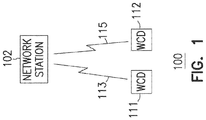
- FIG. 1 shows a wireless communication network 100 including a network station 102 and wireless communication devices 111 and 112, according to some embodiments described herein.
- Network station 102 may be arranged (e.g., configured) to wirelessly communicate with wireless communication device (WCD) 111 through a wireless connection 113 and with WCD 112 through a wireless connection 115.
- WCD wireless communication device
- wireless communication network 100 includes an Evolved Universal Terrestrial Radio Access Network (E-UTRAN) using the 3rd Generation Partnership Project (3GPP) Long Term Evolution (LTE) standards. Additional examples of wireless communication network 100 include Worldwide Interoperability for Microwave Access (WiMax) networks, 3rd Generation (3G) networks, Wi-Fi networks, and other wireless data communication networks.
- E-UTRAN Evolved Universal Terrestrial Radio Access Network
- 3GPP 3rd Generation Partnership Project
- LTE Long Term Evolution
- WiMax Worldwide Interoperability for Microwave Access
- 3G 3rd Generation
- Wi-Fi Worldwide Interoperability for Microwave Access
- An example of network station 102 includes a base station (BS), an Enhanced Node B (eNB), an Access Point (AP), or another type of network station or network equipment.
- Network station 102 may be arranged to operate based on the 3GPP-LTE standards or other wireless data communication standards.
- network station 102 may be configured to transmit orthogonal frequency division multiplexed (OFDM) communication signals over a multicarrier communication channel in accordance with an orthogonal frequency division multiple access (OFDMA) communication technique.
- OFDM signals may comprise a plurality of orthogonal subcarriers.
- OFDMA communication technique may be either an FDD technique that uses different uplink and downlink spectrum or a TDD technique that uses the same spectrum for uplink and downlink.
- wireless communication network 100 may operate based on IEEE 802.11 standards including IEEE 802.11 High Efficiency WLAN (HEW) standard.
- network station 102 may include an access point that may operate as a master station which may be arranged to contend for a wireless medium (e.g., during a contention period) to receive exclusive control of the medium for an HEW control period (i.e., a transmission opportunity (TXOP)).
- the master station may transmit an HEW master-sync transmission at the beginning of the HEW control period.
- HEW stations may communicate with the master station in accordance with a non-contention based multiple access technique.
- the master station may communicate with HEW stations using one or more HEW frames.
- legacy stations refrain from communicating.
- the master-sync transmission may be referred to as an HEW control and schedule transmission.
- the multiple-access technique used during the HEW control period may be a scheduled OFDMA technique, although this is not a requirement.
- the multiple access technique may be a time-division multiple access (TDMA) technique or a frequency division multiple access (FDMA) technique.
- the multiple access technique may be a space-division multiple access (SDMA) technique.
- the master station may also communicate with legacy stations in accordance with legacy IEEE 802.11 communication techniques.
- the master station may also be configurable communicate with HEW stations outside the HEW control period in accordance with legacy IEEE 802.11 communication techniques, although this is not a requirement.
- the links of an HEW frame may be configurable to have the same bandwidth and the bandwidth may be one of 20MHz, 40MHz, 80MHz or 160MHz. In some embodiments, a 320MHz bandwidth may be used. In some embodiments, bandwidths of 5MHz and/or 10MHz may also be used. In these embodiments, each link of an HEW frame may be configured for transmitting a number of spatial streams.
- examples of WCDs 111 and 112 include user equipment (UE) and terminal equipment (e.g., data terminal equipment).
- user equipment and terminal equipment include cellular telephones (e.g., smartphones), tablet computers, e-readers (e.g., e-book readers), notebook computers, laptop computers, desktop computers, personal computers, servers, personal digital assistants (PDAs), digital cameras, medical devices (e.g., a heart rate monitor, a blood pressure monitor, etc.), televisions, web appliances, set-top boxes (STBs), network routers, network switches, network bridges, parking meters, sensors, and other types devices and equipment.
- PDAs personal digital assistants
- STBs set-top boxes
- WCDs 111 and 112 may be arranged (e.g., configured) to operate based on the 3GPP-LTE standards or other wireless data communication standards.
- FIG. 1 shows wireless communication network 100 including only two WCDs (WCDs 111 and 112) to communicate with network station 102 as an example.
- Wireless communication network 100 may include more than two WCDs.
- Network station 102 may have a simultaneous transmit (Tx) and receive (Rx) capability (STR capability), such that it may operate in STR mode (e.g., full-duplex mode) to simultaneously (e.g., concurrently) transmit and receive signals (e.g., radio-frequency (RF) signals).
- Network station 102 may include an RF transceiver that has a full-duplex capability that may operate in full-duplex mode to simultaneously transmit and receive signals.
- network station 102 may transmit a downlink (DL) signal to WCD 111 while network station 102 receives an uplink (UL) signal from WCD 112 at the same time at the same RF carrier.
- UL uplink
- network station 102 may transmit a DL signal to WCD 112 while network station 102 receives a UL signal from WCD 111.
- Network station 102 and WCDs 111 and 112 may be arranged to operate such that a DL signal (e.g., transmitted by network station 102) and a UL signal (e.g., transmitted by WCD 111 or 112) may be transmitted at the same time at the same RF carrier (e.g., a single RF carrier).
- This technique may allow wireless communication network 100 to increase (e.g., double) its handing capacity in comparison with other techniques, such as FDD and TDD.
- a UL signal transmitted by one WCD may cause interference in a DL signal transmitted by network station 102 to another WCD when the DL and UL signals have the same RF carrier and are transmitted at the same time.
- a DL signal transmitted by network station 102
- WCD 111 a DL signal (transmitted by network station 102) received by one of the WCDs 111 and 112 (e.g., WCD 111) may be interfered with by a stronger UL signal transmitted by the other WCD (e.g., WCD 112).
- each of WCDs 111 and 112 may employ components to perform an interference cancellation operation to cancel (e.g., reduce or eliminate) the interference, as described in more detail below.
- FIG. 2 is a diagram showing example signals communicated between network station 102 and each of WCD 111 and 112 of FIG. 1 , according to some embodiments described herein.
- network station 102 may operate in STR mode to transmit a signal (e.g., DL signal) 201 to WCD 111 and to receive a signal (e.g., UL signal) 202 transmitted by WCD 112.
- Signals 201 and 202 may have the same RF carrier f 1 .
- network station 102 may also operate in STR mode to transmit a signal (e.g., DL signal) 203 to WCD 112 and to receive a signal (e.g., UL signal) 204 transmitted by WCD 111.
- Signals 204 and 203 may also have the same RF carrier f 1 .
- network station 102 may also operate in STR mode to simultaneously transmit and receive additional signals (not shown).
- WCD 111 may or may not have the STR capability. If WCD 111 does not have the STR capability, it may be a half-duplex device that operates in a half-duplex mode, such as in only Rx mode or in only Tx mode but not in both modes at the same time at the same RF carrier. WCD 111 may switch from one mode to another depending on whether it receives or transmits signals. For example, WCD 111 may switch from an Rx mode 211 to a Tx mode 212 during a time interval 213. WCD 111 may switch from Tx mode 212 to a mode 219 during a time interval 215. Thus, in the example of FIG.
- WCD 111 may operate in a half-duplex mode (e.g., Rx mode 211) during time interval 231 to receive signal 201 and subsequently operate in a half-duplex mode (e.g., Tx mode 212) during time interval 232 to transmit signal 204.
- a half-duplex mode e.g., Rx mode 211
- Tx mode 212 e.g., Tx mode 212
- WCD 111 may be a full-duplex device that has the capability of operating in STR mode (both Rx and Tx modes at the same time at the same RF carrier). In some cases, although WCD 111 may have the STR capability, it may operate in only Rx mode (e.g., during time interval 231), or in only Tx mode (e.g., during time interval 232). If WCD 111 has the STR capability, it may switch between a half-duplex mode (e.g., Rx mode 211 or Tx mode 212) and a full-duplex mode (e.g., mode 219). Thus, in the example of FIG.
- WCD 111 may operate in a half-duplex mode (e.g., Rx mode 211) during time interval 231 to receive signal 201, operate in a half-duplex mode (e.g., Tx mode 212) during time interval 232 to transmit signal 204, or operate in a full-duplex mode 219 (e.g., STR mode) to simultaneously transmit and receive signals (not shown).
- a half-duplex mode e.g., Rx mode 211
- Tx mode 212 e.g., Tx mode 212
- a full-duplex mode 219 e.g., STR mode
- WCD 112 may or may not have the STR capability. If WCD 112 does not have the STR capability, it may be a half-duplex device that operates in a half-duplex mode, such as in only Rx mode or in only Tx mode but not in both modes at the same time. WCD 112 may switch from one mode to another depending on whether it receives or transmits signals. For example, WCD 112 may switch from a Tx mode 222 to an Rx mode 221 during a time interval 223. WCD 112 may switch from Rx mode 221 to a mode 229 during a time interval 225. Thus, in the example of FIG.
- WCD 112 may operate in a half-duplex mode (e.g., Tx mode 222) during time interval 231 to transmit signal 202 and subsequently operate in a half-duplex mode (e.g., Rx mode 221) during time interval 232 to receive signal 203.
- a half-duplex mode e.g., Tx mode 222
- Rx mode 221 e.g., Rx mode 221
- WCD 112 may be a full-duplex device that has the capability of operating in STR mode (both Rx and Tx modes at the same time). In some cases, although WCD 112 may have the STR capability, it may operate in only Tx mode (e.g., during time interval 231), or in only Rx mode (e.g., during time interval 232). If WCD 112 has the STR capability, it may switch between a half-duplex mode (e.g., Rx mode 221 or Tx mode 222) and a full-duplex mode (e.g., mode 229). Thus, in the example of FIG.
- WCD 112 may operate in a half-duplex mode (e.g., Tx mode 222) during time interval 231 to transmit signal 202, operate in a half-duplex mode (e.g., Rx mode 221) during time interval 232 to receive signal 203, or operate in a full-duplex mode 229 (e.g., STR mode) to simultaneously transmit and receive signals (not shown).
- a half-duplex mode e.g., Tx mode 222
- Rx mode 221 e.g., Rx mode 221
- a full-duplex mode 229 e.g., STR mode
- a UL signal transmitted by one WCD may cause interference to a DL signal received by another WCD when the DL and UL signals have the same RF carrier and are transmitted at the same time.
- a situation may happen during time interval 231 or 232 in FIG. 2 .
- signal 201 e.g., DL signal
- WCD 111 may be interfered with by a stronger signal 202 (e.g., UL signal) transmitted by WCD 112.
- signal 203 e.g., DL signal
- signal 204 e.g., UL signal
- WCD 111 may perform an interference cancellation operation during time interval 231 to cancel interference caused by signal 202 to signal 201.
- WCD 112 may perform an interference cancellation operation during time interval 232 to cancel interference caused by signal 204 to signal 203.
- the interference cancellation operation employed by WCD 111 and WCD 112 may improve or maintain the accuracy of information (e.g., data) associated with the signal (e.g., signal 201 or 203) received by the receiving WCD.
- the interference cancellation operation employed by WCD 111 and WCD 112 may also improve some of the operations in network station 102.
- network station 102 may include a scheduler to schedule transmissions of DL and UL signals.
- WCD e.g., WCD 111 or 112
- network station 102 may schedule transmissions of DL and UL signals such that any two WCDs (one for receiving a DL signal and the other for transmitting a UL signal) should have enough distance between them (e.g., should not be near each other) to avoid WCD-to-WCD interference. This distance factor may place a constraint in scheduler design in network station 102.
- network station 102 may not be able to freely select arbitrary WCDs for DL or UL transmission at a particular moment, even if the WCDs need either DL or UL transmission at that particular moment, because a potential WCD-to-WCD interference may occur.
- the above-mentioned constraint may be removed from the scheduling operation in network station 102 because WCD-to-WCD interference (if it occurs) may be cancelled by the interference cancellation operation described herein.
- latency of signal (e.g., data packet) delivery may be improved and scheduler design may be simpler for network station 102.
- FIG. 3 shows a block diagram of a WCD 300 including a receiver 310 and an interference cancellation unit 320, according to some embodiments described herein.
- WCD 300 may correspond to WCD 111 or WCD 112 of FIG. 1 .
- WCD 111 or WCD 112 may include components and operations of WCD 300.
- Receiver 310 may operate to receive a DL signal from a network station (e.g., network station 102 in FIG. 1 ).
- Interference cancellation unit 320 may operate to perform an interference cancellation operation to cancel interference in the DL signal that may be caused by another signal (e.g., a UL signal) from another device near WCD 300.
- the interference cancellation operation performed by interference cancellation unit 320 may include a successive interference cancellation (SIC) operation.
- interference cancellation unit 320 may include components to perform an SIC operation.
- FIG. 3 omits some of the components that may be used in an SIC operation.
- WCD 300 may include an antenna 301 to receive an RF signal 302.
- Receiver 310 may include a down converter 312 to down-convert signal 302 and generate a baseband signal 313, and an analog-to- digital converter (ADC) 314 to receive baseband signal 313 and generate a received signal 315, which includes a baseband digital signal.
- ADC analog-to- digital converter
- Signal 302 received by antenna 301 may include a DL signal (e.g., signal 201 in FIG. 2 ) transmitted by a network station (e.g., network station 102 in FIG. 1 ) intended for WCD 300.
- signal 302 may also include another signal in addition to the DL signal.
- a UL signal e.g., signal 202 in FIG. 2
- the UL signal may interfere with the DL signal if that device is near enough to WCD 300 to cause the interference.
- signal 302 may include both the information associated with the DL signal intended for WCD 300 and the information associate with the UL signal that causes the interference.
- Interference cancellation unit 320 may include a demodulator 321 to demodulate received signal 315 and generate a demodulated signal 322, and a decoder 323 to decode demodulated signal 322 to generate a decoded signal 328.
- Interference cancellation unit 320 may obtain interference information (e.g., information associated with the signal (e.g., UL signal) that causes the interference) based on decoded signal 328.
- Interference cancellation unit 320 may then regenerate the interference based on the interference information.
- Interference cancellation unit 320 may also include an encoder 324 to generate an encoded signal 325 (which includes the regenerated interference) based on the interference information included in the decoded signal 328, and a modulator 326 to modulate encoded signal 325 to generate interference cancellation signal 327. Interference cancellation unit 320 may then subtract interference cancellation signal 327 from received signal 315 in order to cancel interference in the DL signal.
- an encoder 324 to generate an encoded signal 325 (which includes the regenerated interference) based on the interference information included in the decoded signal 328
- a modulator 326 to modulate encoded signal 325 to generate interference cancellation signal 327.
- Interference cancellation unit 320 may then subtract interference cancellation signal 327 from received signal 315 in order to cancel interference in the DL signal.
- Decoded signal 328 may also be used to generate a data signal (not shown) that contains information (e.g., bits of a data stream) associated with the DL signal intended for WCD 300. For example, after interference cancellation signal 327 is subtracted from received signal 315, a resulting signal is generated. Thus, decoded signal 328 may include updated information based on the resulting signal. Then, the data signal may be generated by further decoding the updated information. The data signal may be provided to other components (not shown) of WCD 300 for further processing.
- information e.g., bits of a data stream
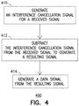
- FIG. 4 is a flow chart showing a method 400 of operating a WCD, according to some embodiments described herein.
- Method 400 may be performed by a WCD, such as WCD 111, 112, or 300 described above or WCD 500 described below.
- the WCD used in method 400 is incapable of simultaneously transmitting and receiving signals.
- the WCD used in method 400 is capable of simultaneously transmitting and receiving signals.
- the WCD used in method 400 may communicate (e.g., by way of DL signal or UL signal, or both) with a network station (e.g., network station 102).
- the network station is capable of simultaneously transmitting and receiving signals.
- method 400 may include activities 410, 412, and 414.
- Activity 410 may include generating an interference cancellation signal for a received signal (e.g., received signal 315 in FIG. 3 ). Generating the interference cancellation signal in activity 410 may include down-converting an RF signal (e.g., signal 302 in FIG. 3 ) to generate a down-converted baseband signal, generating a received signal (e.g., a digital baseband signal) based on the baseband signal, demodulating the received signal to generate a demodulated signal, decoding the demodulated signal to generated a decoded signal, obtaining interference information from the decoded signal in order to regenerate the interference, and generating the interference cancellation signal based on the interference information. Activity 410 may also include encoding the interference information to generate an encoded signal (which includes the regenerated interference), and modulating the encoded signal to generate the interference cancellation signal.
- an encoded signal which includes the regenerated interference
- Activity 412 of method 400 may include subtracting the interference cancellation signal from the received signal.
- the subtraction may generate a resulting signal (e.g., the remaining portion the received signal after the interference cancellation signal is subtracted from it).
- Activity 414 may include generating a data signal. Generating the data signal may include decoding the resulting signal (generated in activity 412). The data signal may include information associated with a DL signal transmitted to the WCD by a network station. Activity 414 may also include providing the data signal to other components of the WCD for further processing.
- Method 400 may include performing an SIC operation, such that one or more of the activities 410, 412, and 414 may be included as part of the SIC operation.
- Method 400 may include fewer or more activities than the activities shown in FIG. 4 .
- method 400 may include activities associated with the operations of WCD 111, 112, or 300 described above with reference to FIG. 1 through FIG. 3 , and operations of a WCD described below with reference to FIG. 5 .
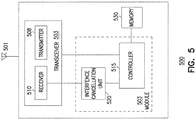
- FIG. 5 shows a block diagram of a WCD 500 including a module 502, according to some embodiments described herein.
- WCD 500 may correspond to WCD 111 or WCD 112 ( FIG. 1 ) or WCD 300 ( FIG. 3 ).
- WCD 111, WCD 112, or WCD 300 may include components and operations of WCD 500.
- WCD 500 may also include at least one antenna 501 (e.g., a single antenna or multiple antennas), a transceiver 503 having a transmitter 508 and a receiver 510, and a memory 530.
- Receiver 510 may correspond to receiver 310 of FIG. 3 .
- receiver 510 may be arranged to operate in ways similar to, or identical to, those of receiver 310.
- Module 502 may include a controller 515 and an interference cancellation unit 520.
- Interference cancellation unit 520 may correspond to interference cancellation unit 320 of FIG. 3 .
- interference cancellation unit 520 may be arranged to operate in ways similar to, or identical to, those of interference cancellation unit 320.
- WCD 500 may also include one or more of a keyboard, a display (e.g., an LCD screen including a touch screen), a non-volatile memory port (e.g., a Universal Serial Bus (USB) port), speakers, and other mobile device elements.
- a keyboard e.g., a keyboard
- a display e.g., an LCD screen including a touch screen
- a non-volatile memory port e.g., a Universal Serial Bus (USB) port
- Module 502 and transceiver 503 may be arranged (e.g., configured) to perform operations described above with reference to FIG. 1 through FIG. 4 .
- receiver 510 may be arranged to receive a DL signal (e.g., signal 201 or 203 in FIG. 2 ) transmitted by a network station (e.g., network station 102 in FIG. 1 ).
- Transmitter 508 may be arranged to transmit a UL signal (e.g., signal 202 or 204 in FIG. 2 ) to a network station (e.g., network station 102 in FIG. 1 ).
- WCD 500 may be an STR incapable device, such that transceiver 503 may be a half-duplex transceiver.
- WCD 500 may be an STR capable device, such that transceiver 503 may be full-duplex transceiver.
- Module 502 may be arranged to perform an interference cancellation operation to cancel inference to a signal (e.g., signal 201 or 203 in FIG. 2 ).
- the interference cancellation operation performed by module 502 may be similar to, or identical to, that described above with reference to FIG. 1 through FIG. 4 .
- Module 502 may use at least one of interference cancellation unit 520 and controller 515 to perform the interference cancellation operation.
- Controller 515 may be arranged (e.g., configured) to provide processing and control functionalities for WCD 500, including at least part of the interference cancellation operation described above with reference to FIG. 1 through FIG. 4 .
- Controller 515 may include one or more processors that may include one or more central processing units (CPUs), one or more graphics processing units (GPUs), or a combination of one or more CPUs and one or more GPUs.
- CPUs central processing units
- GPUs graphics processing units
- Memory 530 may include volatile memory, non-volatile memory, or a combination of both.
- Memory 530 may store instructions (e.g., firmware programs, software programs, or a combination of both).
- Controller 515 may execute instructions in memory 530 to result in WCD 500 performing operations such as the interference cancellation operation performed by WCD 111, 112, or 300, described in method 400, described herein with reference to FIG. 1 through FIG. 4 .
- the at least one antenna 501 may include one or more directional or omnidirectional antennas, including, for example, dipole antennas, monopole antennas, patch antennas, loop antennas, microstrip antennas or other types of antennas suitable for transmission of RF signals. In some embodiments, instead of two or more antennas, a single antenna with multiple apertures may be used. In these embodiments, each aperture may be considered a separate antenna.
- the at least one antenna 501 may be arranged to support multiple-input and multipleoutput (MIMO) communications. In some MIMO embodiments, the at least one antenna 501 may be effectively separated to benefit from spatial diversity and the different channel characteristics that may result between each of the at least one antenna 501 and the antennas of a transmitting station. In some MIMO embodiments, the at least one antenna 501 may be separated by up to 1/10 of a wavelength or more.
- FIG. 5 shows WCD 500 including one transceiver 503 and at least one antenna 501 as an example.
- the number of transceivers and antennas may vary.
- Module 502 and transceiver 503 may be arranged to operate in different communication networks, such as a 3GPP-LTE network, a WiMax network, and other communication networks.
- the WCD 500 may be configured to receive (e.g., from network station 102 in FIG. 1 ) OFDM communication signals in accordance with an OFDMA communication technique.
- the OFDM signals may comprise a plurality of orthogonal subcarriers.
- WCD 500 is shown as having several separate functional elements, one or more of the functional elements may be combined and may be implemented by combinations of software-configured elements, such as processing elements including digital signal processors (DSPs), and/or other hardware elements.
- DSPs digital signal processors
- some elements may comprise one or more microprocessors, DSPs, application specific integrated circuits (ASICs), radio-frequency integrated circuits (RFICs) and combinations of various hardware and logic circuitry for performing at least the functions and operations described herein.
- the functional elements may refer to one or more processes operating on one or more processing elements.
- Embodiments may be implemented in one or a combination of hardware, firmware and software. Embodiments may also be implemented as instructions (e.g., firmware programs, software programs, or a combination of both) stored on a computer-readable storage medium, which may be read and executed by at least one processor to perform the operations described herein.
- a computer-readable storage medium may include any non-transitory mechanism (e.g., non-transitory computer-readable medium) for storing information (e.g., instructions) in a form readable by a machine (e.g., a computer). Examples of a computer-readable storage medium may include read-only memory (ROM), random-access memory (RAM), magnetic disk storage media, optical storage media, flash-memory devices, and other storage devices and media.
- ROM read-only memory
- RAM random-access memory
- magnetic disk storage media e.g., optical storage media
- flash-memory devices e.g., flash-memory devices
- one or more processors of the WCD 500 may
Landscapes
- Engineering & Computer Science (AREA)
- Signal Processing (AREA)
- Computer Networks & Wireless Communication (AREA)
- Quality & Reliability (AREA)
- Mobile Radio Communication Systems (AREA)
Claims (15)
- Dispositif de communication sans fil (111), WCD, comprenant :
un récepteur (310) destiné à générer un signal reçu (315), le signal reçu (315) comportant au moins un premier signal transmis au WCD (111) par une station de réseau (102) fonctionnant dans un mode duplex intégral tandis que le WCD (111) fonctionne dans un mode semi-duplex ; et caractérisé par :un module (320) destiné à générer un signal d'annulation d'interférence (327) pour le signal reçu (315) sur la base d'informations d'interférence obtenues à partir au moins du signal reçu, les informations d'interférence étant associées à un deuxième signal (115) transmis à la station de réseau (102) par un dispositif additionnel (112), le premier signal étant transmis par la station de réseau (102) au WCD dans le même intervalle de temps que celui dans lequel le deuxième signal est transmis par le dispositif additionnel (112) et les premier et deuxième signaux comportant une même porteuse radiofréquence, RF ; etun soustracteur destiné à soustraire le signal d'annulation d'interférence (327) au signal reçu (315) avant que le signal reçu soit appliqué au module. - WCD (111) selon la revendication 1, dans lequel le premier signal comporte un signal en liaison descendante transmis par la station de réseau (102) au WCD (111), et le deuxième signal comporte un signal en liaison montante transmis par le dispositif additionnel (112) à la station de réseau (102).
- WCD (111) selon la revendication 1, dans lequel le premier signal comporte un signal en liaison descendante transmis par la station de réseau (102) au WCD (111) sur la base d'une technique de communication à accès multiple par répartition orthogonale de la fréquence, OFDMA.
- WCD (111) selon la revendication 1, lequel WCD (111) est un dispositif semi-duplex, et dans lequel la station de réseau (102) est conçue pour transmettre le premier signal tandis que la station de réseau reçoit le deuxième signal.
- WCD (111) selon l'une quelconque des revendications 1 à 4, dans lequel le soustracteur est conçu pour :soustraire le signal d'annulation d'interférence (327) au signal reçu (315) afin de générer un signal résultant ; etle module est conçu pour décoder le signal résultant afin de générer un signal de données, le signal de données comportant des informations associées au premier signal provenant de la station de réseau (102).
- WCD (111) selon l'une quelconque des revendications 1 à 4, dans lequel le module (320) est conçu pour réaliser une opération d'annulation d'interférence successive afin d'obtenir les informations d'interférence.
- WCD (111) selon l'une quelconque des revendications 1 à 4, dans lequel le récepteur (310) est conçu pour :générer un signal en bande de base (313) sur la base d'un signal reçu par une antenne (301) couplée au récepteur (310) ; etgénérer un signal numérique en bande de base sur la base du signal en bande de base (313), le signal numérique en bande de base comportant le signal reçu (315).
- WCD (111) selon la revendication 7, dans lequel le module (320) est conçu pour :démoduler le signal reçu (315) afin de générer un signal démodulé (322) ;décoder le signal démodulé (322) afin de générer un signal décodé (328) ; etobtenir les informations d'interférence sur la base du signal décodé (328).
- WCD (111) selon l'une quelconque des revendications 1 à 4, dans lequel la station de réseau (102) comporte soit une station de base, soit un nœud B évolué, eNB.
- Procédé (400) permettant de faire fonctionner un dispositif de communication sans fil (111), WCD, le procédé comprenant :la génération (410) d'un signal d'annulation d'interférence (327) sur la base au moins en partie d'un signal reçu au niveau d'un récepteur (310) du WCD, le signal reçu comportant au moins un premier signal transmis au WCD par une station de réseau (102) et le signal d'annulation d'interférence (327) comportant des informations associées à un deuxième signal transmis par un dispositif additionnel (112) à la station de réseau, les premier et deuxième signaux étant transmis durant un même intervalle de temps et les premier et deuxième signaux comportant une même porteuse radiofréquence, RF ; etla soustraction (412) du signal d'annulation d'interférence (327) au signal reçu (315).
- Procédé (400) selon la revendication 10, dans lequel la génération (400) du signal d'annulation d'interférence est réalisée dans le cadre d'une opération d'annulation d'interférence successive.
- Procédé (400) selon la revendication 10 ou 11, dans lequel la génération (410) du signal d'annulation d'interférence comporte :la démodulation du signal reçu (315) afin de générer un signal démodulé (322) ;le décodage du signal démodulé (322) afin de générer un signal décodé (328) ;l'obtention d'informations d'interférence à partir du signal décodé (328) ; etla génération du signal d'annulation d'interférence (327) sur la base des informations d'interférence.
- Procédé (400) selon la revendication 10 ou 11, comprenant en outre :la réception d'un signal radiofréquence, RF, le WCD (111) se trouvant dans un mode semi-duplex au moment de la réception du signal RF ;la conversion par abaissement de fréquence du signal RF afin de générer un signal en bande de base (313) ; etla génération d'un signal numérique en bande de base sur la base du signal en bande de base (313), le signal numérique en bande de base comportant le signal reçu.
- Procédé (400) selon la revendication 10 ou 11, dans lequel le premier signal comporte un signal en liaison descendante et le deuxième signal comporte un signal en liaison montante, et le WCD (111) et le dispositif additionnel (112) sont proches l'un de l'autre si bien que le signal en liaison descendante reçu par le WCD est interféré par le signal en liaison montante.
- Support de stockage lisible par ordinateur pour le stockage d'informations dont l'exécution donne lieu à la mise en œuvre d'un procédé ou la matérialisation d'un appareil selon l'une quelconque des revendications précédentes.
Applications Claiming Priority (1)
| Application Number | Priority Date | Filing Date | Title |
|---|---|---|---|
| PCT/US2014/036966 WO2015171119A1 (fr) | 2014-05-06 | 2014-05-06 | Suppression d'interférence pour des signaux ayant la même porteuse radiofréquence et transmis au même moment |
Publications (3)
| Publication Number | Publication Date |
|---|---|
| EP3140929A1 EP3140929A1 (fr) | 2017-03-15 |
| EP3140929A4 EP3140929A4 (fr) | 2017-12-20 |
| EP3140929B1 true EP3140929B1 (fr) | 2021-03-17 |
Family
ID=54392789
Family Applications (1)
| Application Number | Title | Priority Date | Filing Date |
|---|---|---|---|
| EP14891246.2A Active EP3140929B1 (fr) | 2014-05-06 | 2014-05-06 | Suppression d'interférence pour des signaux ayant la même porteuse radiofréquence et transmis au même moment |
Country Status (4)
| Country | Link |
|---|---|
| US (1) | US20170141867A1 (fr) |
| EP (1) | EP3140929B1 (fr) |
| TW (1) | TWI569593B (fr) |
| WO (1) | WO2015171119A1 (fr) |
Families Citing this family (2)
| Publication number | Priority date | Publication date | Assignee | Title |
|---|---|---|---|---|
| US11050468B2 (en) * | 2014-04-16 | 2021-06-29 | Rearden, Llc | Systems and methods for mitigating interference within actively used spectrum |
| US9811495B2 (en) * | 2014-08-27 | 2017-11-07 | Lattice Semiconductor Corporation | Arbitration signaling within a multimedia high definition link (MHL 3) device |
Family Cites Families (10)
| Publication number | Priority date | Publication date | Assignee | Title |
|---|---|---|---|---|
| US7817641B1 (en) * | 2005-10-20 | 2010-10-19 | Amir Keyvan Khandani | Methods for spatial multiplexing of wireless two-way channels |
| US9859949B2 (en) * | 2010-01-11 | 2018-01-02 | Qualcomm Incorporated | Blind uplink interference cancellation in wireless networking |
| KR101672769B1 (ko) * | 2010-02-09 | 2016-11-04 | 삼성전자주식회사 | 겹치는 무선 자원을 이용하여 업링크 통신 및 다운링크 통신을 수행하는 통신 시스템 |
| US9049730B2 (en) * | 2011-11-14 | 2015-06-02 | Qualcomm Incorporated | Uplink data transmission with interference mitigation |
| CN103209415B (zh) * | 2012-01-16 | 2017-08-04 | 华为技术有限公司 | 全双工干扰处理方法和装置 |
| US9668167B2 (en) * | 2012-03-16 | 2017-05-30 | Qualcomm Incorporated | Transport block size limitation for enhanced control channel operation in LTE |
| WO2013173252A1 (fr) * | 2012-05-13 | 2013-11-21 | Invention Mine Llc | Transmission sans fil bilatérale simultanée avec cryptage basé sur la phase de canal |
| US8804583B2 (en) * | 2012-07-13 | 2014-08-12 | At&T Intellectual Property I, L.P. | System and method for medium access control enabling both full-duplex and half-duplex communications |
| GB2505684A (en) * | 2012-09-07 | 2014-03-12 | Enmodus Ltd | Cancellation of transmitter leakage in a transceiver using a predetermined phase relationship between transmit and receive carriers |
| US10110264B2 (en) * | 2013-09-13 | 2018-10-23 | Blackberry Limited | Full duplex resource reuse enablement |
-
2014
- 2014-05-06 WO PCT/US2014/036966 patent/WO2015171119A1/fr not_active Ceased
- 2014-05-06 EP EP14891246.2A patent/EP3140929B1/fr active Active
- 2014-05-06 US US15/129,595 patent/US20170141867A1/en not_active Abandoned
-
2015
- 2015-04-01 TW TW104110733A patent/TWI569593B/zh active
Non-Patent Citations (1)
| Title |
|---|
| None * |
Also Published As
| Publication number | Publication date |
|---|---|
| EP3140929A1 (fr) | 2017-03-15 |
| TWI569593B (zh) | 2017-02-01 |
| WO2015171119A1 (fr) | 2015-11-12 |
| US20170141867A1 (en) | 2017-05-18 |
| EP3140929A4 (fr) | 2017-12-20 |
| TW201543830A (zh) | 2015-11-16 |
Similar Documents
| Publication | Publication Date | Title |
|---|---|---|
| US10348469B2 (en) | Hew master station and method for communicating in accordance with a scheduled OFDMA technique on secondary channels | |
| EP3593585B1 (fr) | Conception de signal de réservation de canal pour spectre partagé | |
| CN104321985B (zh) | 用于在宽带宽的宽带网络中操作窄带宽用户设备的演进型节点b、用户设备和方法 | |
| EP3684102B1 (fr) | Techniques de gestion de transmissions dans une bande de spectre de radiofréquences sans licence | |
| US11616633B2 (en) | Half-duplex operation in new radio frequency division duplexing bands | |
| US12470358B2 (en) | Downlink pre-emption and uplink cancellation for full-duplex systems | |
| US12349150B2 (en) | Multiple sounding reference signal transmissions triggered by downlink control information | |
| US20170041171A1 (en) | Bandwidth and sub-channel indication | |
| US11646859B2 (en) | Unified transmission configuration indicator windows | |
| US12542634B2 (en) | Uplink demodulation reference signal bundling modes | |
| US20250220678A1 (en) | Cross link interference mitigation in full-duplex networks | |
| CN115997453A (zh) | 在不同载波上的上行链路传输和srs传输的管理 | |
| US20210235441A1 (en) | Control resource configurations | |
| US20230389005A1 (en) | User equipment indication of preferred timing adjustment | |
| EP3140929B1 (fr) | Suppression d'interférence pour des signaux ayant la même porteuse radiofréquence et transmis au même moment | |
| CN115486020A (zh) | 搭载的下行链路控制信息的层映射方法 | |
| US12532321B2 (en) | Parameter switch per semi-persistent scheduling and configured grant occasion | |
| EP4282113A1 (fr) | Procédés et appareil permettant d'utiliser des symboles ul pour des transmissions de harq-ack à sps différé | |
| WO2021062603A1 (fr) | Réduction de surdébit de signal de référence | |
| WO2025235752A1 (fr) | Techniques de résolution de collisions multiples dans des symboles duplex intégral de sous-bande (sbfd) | |
| EP4690613A1 (fr) | Planification pendant des créneaux avec ressources en duplex intégral de sous-bande | |
| WO2022155415A1 (fr) | Transmissions de signaux de référence de sondage multiples déclenchées par des informations de commande de liaison descendante | |
| CN119054318A (zh) | 用于时域信道状态信息报告的缓冲限制 |
Legal Events
| Date | Code | Title | Description |
|---|---|---|---|
| PUAI | Public reference made under article 153(3) epc to a published international application that has entered the european phase |
Free format text: ORIGINAL CODE: 0009012 |
|
| STAA | Information on the status of an ep patent application or granted ep patent |
Free format text: STATUS: REQUEST FOR EXAMINATION WAS MADE |
|
| 17P | Request for examination filed |
Effective date: 20161003 |
|
| AK | Designated contracting states |
Kind code of ref document: A1 Designated state(s): AL AT BE BG CH CY CZ DE DK EE ES FI FR GB GR HR HU IE IS IT LI LT LU LV MC MK MT NL NO PL PT RO RS SE SI SK SM TR |
|
| AX | Request for extension of the european patent |
Extension state: BA ME |
|
| DAX | Request for extension of the european patent (deleted) | ||
| A4 | Supplementary search report drawn up and despatched |
Effective date: 20171121 |
|
| RIC1 | Information provided on ipc code assigned before grant |
Ipc: H04J 11/00 20060101ALI20171115BHEP Ipc: H04B 15/02 20060101AFI20171115BHEP |
|
| STAA | Information on the status of an ep patent application or granted ep patent |
Free format text: STATUS: EXAMINATION IS IN PROGRESS |
|
| 17Q | First examination report despatched |
Effective date: 20190103 |
|
| REG | Reference to a national code |
Ref country code: DE Ref legal event code: R079 Ref document number: 602014075853 Country of ref document: DE Free format text: PREVIOUS MAIN CLASS: H04B0015020000 Ipc: H04J0011000000 |
|
| RIC1 | Information provided on ipc code assigned before grant |
Ipc: H04J 11/00 20060101AFI20200217BHEP |
|
| GRAP | Despatch of communication of intention to grant a patent |
Free format text: ORIGINAL CODE: EPIDOSNIGR1 |
|
| STAA | Information on the status of an ep patent application or granted ep patent |
Free format text: STATUS: GRANT OF PATENT IS INTENDED |
|
| INTG | Intention to grant announced |
Effective date: 20200421 |
|
| GRAJ | Information related to disapproval of communication of intention to grant by the applicant or resumption of examination proceedings by the epo deleted |
Free format text: ORIGINAL CODE: EPIDOSDIGR1 |
|
| STAA | Information on the status of an ep patent application or granted ep patent |
Free format text: STATUS: EXAMINATION IS IN PROGRESS |
|
| INTC | Intention to grant announced (deleted) | ||
| GRAP | Despatch of communication of intention to grant a patent |
Free format text: ORIGINAL CODE: EPIDOSNIGR1 |
|
| STAA | Information on the status of an ep patent application or granted ep patent |
Free format text: STATUS: GRANT OF PATENT IS INTENDED |
|
| INTG | Intention to grant announced |
Effective date: 20201014 |
|
| GRAS | Grant fee paid |
Free format text: ORIGINAL CODE: EPIDOSNIGR3 |
|
| GRAA | (expected) grant |
Free format text: ORIGINAL CODE: 0009210 |
|
| STAA | Information on the status of an ep patent application or granted ep patent |
Free format text: STATUS: THE PATENT HAS BEEN GRANTED |
|
| AK | Designated contracting states |
Kind code of ref document: B1 Designated state(s): AL AT BE BG CH CY CZ DE DK EE ES FI FR GB GR HR HU IE IS IT LI LT LU LV MC MK MT NL NO PL PT RO RS SE SI SK SM TR |
|
| REG | Reference to a national code |
Ref country code: GB Ref legal event code: FG4D |
|
| REG | Reference to a national code |
Ref country code: CH Ref legal event code: EP |
|
| REG | Reference to a national code |
Ref country code: DE Ref legal event code: R096 Ref document number: 602014075853 Country of ref document: DE |
|
| REG | Reference to a national code |
Ref country code: IE Ref legal event code: FG4D |
|
| REG | Reference to a national code |
Ref country code: AT Ref legal event code: REF Ref document number: 1373244 Country of ref document: AT Kind code of ref document: T Effective date: 20210415 |
|
| REG | Reference to a national code |
Ref country code: NL Ref legal event code: FP |
|
| REG | Reference to a national code |
Ref country code: LT Ref legal event code: MG9D |
|
| PG25 | Lapsed in a contracting state [announced via postgrant information from national office to epo] |
Ref country code: NO Free format text: LAPSE BECAUSE OF FAILURE TO SUBMIT A TRANSLATION OF THE DESCRIPTION OR TO PAY THE FEE WITHIN THE PRESCRIBED TIME-LIMIT Effective date: 20210617 Ref country code: BG Free format text: LAPSE BECAUSE OF FAILURE TO SUBMIT A TRANSLATION OF THE DESCRIPTION OR TO PAY THE FEE WITHIN THE PRESCRIBED TIME-LIMIT Effective date: 20210617 Ref country code: HR Free format text: LAPSE BECAUSE OF FAILURE TO SUBMIT A TRANSLATION OF THE DESCRIPTION OR TO PAY THE FEE WITHIN THE PRESCRIBED TIME-LIMIT Effective date: 20210317 Ref country code: GR Free format text: LAPSE BECAUSE OF FAILURE TO SUBMIT A TRANSLATION OF THE DESCRIPTION OR TO PAY THE FEE WITHIN THE PRESCRIBED TIME-LIMIT Effective date: 20210618 Ref country code: FI Free format text: LAPSE BECAUSE OF FAILURE TO SUBMIT A TRANSLATION OF THE DESCRIPTION OR TO PAY THE FEE WITHIN THE PRESCRIBED TIME-LIMIT Effective date: 20210317 |
|
| REG | Reference to a national code |
Ref country code: AT Ref legal event code: MK05 Ref document number: 1373244 Country of ref document: AT Kind code of ref document: T Effective date: 20210317 |
|
| PG25 | Lapsed in a contracting state [announced via postgrant information from national office to epo] |
Ref country code: RS Free format text: LAPSE BECAUSE OF FAILURE TO SUBMIT A TRANSLATION OF THE DESCRIPTION OR TO PAY THE FEE WITHIN THE PRESCRIBED TIME-LIMIT Effective date: 20210317 Ref country code: LV Free format text: LAPSE BECAUSE OF FAILURE TO SUBMIT A TRANSLATION OF THE DESCRIPTION OR TO PAY THE FEE WITHIN THE PRESCRIBED TIME-LIMIT Effective date: 20210317 Ref country code: SE Free format text: LAPSE BECAUSE OF FAILURE TO SUBMIT A TRANSLATION OF THE DESCRIPTION OR TO PAY THE FEE WITHIN THE PRESCRIBED TIME-LIMIT Effective date: 20210317 |
|
| PG25 | Lapsed in a contracting state [announced via postgrant information from national office to epo] |
Ref country code: SM Free format text: LAPSE BECAUSE OF FAILURE TO SUBMIT A TRANSLATION OF THE DESCRIPTION OR TO PAY THE FEE WITHIN THE PRESCRIBED TIME-LIMIT Effective date: 20210317 Ref country code: LT Free format text: LAPSE BECAUSE OF FAILURE TO SUBMIT A TRANSLATION OF THE DESCRIPTION OR TO PAY THE FEE WITHIN THE PRESCRIBED TIME-LIMIT Effective date: 20210317 Ref country code: EE Free format text: LAPSE BECAUSE OF FAILURE TO SUBMIT A TRANSLATION OF THE DESCRIPTION OR TO PAY THE FEE WITHIN THE PRESCRIBED TIME-LIMIT Effective date: 20210317 Ref country code: CZ Free format text: LAPSE BECAUSE OF FAILURE TO SUBMIT A TRANSLATION OF THE DESCRIPTION OR TO PAY THE FEE WITHIN THE PRESCRIBED TIME-LIMIT Effective date: 20210317 Ref country code: AT Free format text: LAPSE BECAUSE OF FAILURE TO SUBMIT A TRANSLATION OF THE DESCRIPTION OR TO PAY THE FEE WITHIN THE PRESCRIBED TIME-LIMIT Effective date: 20210317 |
|
| PG25 | Lapsed in a contracting state [announced via postgrant information from national office to epo] |
Ref country code: IS Free format text: LAPSE BECAUSE OF FAILURE TO SUBMIT A TRANSLATION OF THE DESCRIPTION OR TO PAY THE FEE WITHIN THE PRESCRIBED TIME-LIMIT Effective date: 20210717 Ref country code: PL Free format text: LAPSE BECAUSE OF FAILURE TO SUBMIT A TRANSLATION OF THE DESCRIPTION OR TO PAY THE FEE WITHIN THE PRESCRIBED TIME-LIMIT Effective date: 20210317 Ref country code: PT Free format text: LAPSE BECAUSE OF FAILURE TO SUBMIT A TRANSLATION OF THE DESCRIPTION OR TO PAY THE FEE WITHIN THE PRESCRIBED TIME-LIMIT Effective date: 20210719 Ref country code: ES Free format text: LAPSE BECAUSE OF FAILURE TO SUBMIT A TRANSLATION OF THE DESCRIPTION OR TO PAY THE FEE WITHIN THE PRESCRIBED TIME-LIMIT Effective date: 20210317 Ref country code: RO Free format text: LAPSE BECAUSE OF FAILURE TO SUBMIT A TRANSLATION OF THE DESCRIPTION OR TO PAY THE FEE WITHIN THE PRESCRIBED TIME-LIMIT Effective date: 20210317 Ref country code: SK Free format text: LAPSE BECAUSE OF FAILURE TO SUBMIT A TRANSLATION OF THE DESCRIPTION OR TO PAY THE FEE WITHIN THE PRESCRIBED TIME-LIMIT Effective date: 20210317 |
|
| REG | Reference to a national code |
Ref country code: DE Ref legal event code: R097 Ref document number: 602014075853 Country of ref document: DE |
|
| REG | Reference to a national code |
Ref country code: CH Ref legal event code: PL |
|
| PLBE | No opposition filed within time limit |
Free format text: ORIGINAL CODE: 0009261 |
|
| STAA | Information on the status of an ep patent application or granted ep patent |
Free format text: STATUS: NO OPPOSITION FILED WITHIN TIME LIMIT |
|
| PG25 | Lapsed in a contracting state [announced via postgrant information from national office to epo] |
Ref country code: DK Free format text: LAPSE BECAUSE OF FAILURE TO SUBMIT A TRANSLATION OF THE DESCRIPTION OR TO PAY THE FEE WITHIN THE PRESCRIBED TIME-LIMIT Effective date: 20210317 Ref country code: CH Free format text: LAPSE BECAUSE OF NON-PAYMENT OF DUE FEES Effective date: 20210531 Ref country code: AL Free format text: LAPSE BECAUSE OF FAILURE TO SUBMIT A TRANSLATION OF THE DESCRIPTION OR TO PAY THE FEE WITHIN THE PRESCRIBED TIME-LIMIT Effective date: 20210317 Ref country code: MC Free format text: LAPSE BECAUSE OF FAILURE TO SUBMIT A TRANSLATION OF THE DESCRIPTION OR TO PAY THE FEE WITHIN THE PRESCRIBED TIME-LIMIT Effective date: 20210317 Ref country code: LU Free format text: LAPSE BECAUSE OF NON-PAYMENT OF DUE FEES Effective date: 20210506 Ref country code: LI Free format text: LAPSE BECAUSE OF NON-PAYMENT OF DUE FEES Effective date: 20210531 |
|
| REG | Reference to a national code |
Ref country code: BE Ref legal event code: MM Effective date: 20210531 |
|
| 26N | No opposition filed |
Effective date: 20211220 |
|
| PG25 | Lapsed in a contracting state [announced via postgrant information from national office to epo] |
Ref country code: SI Free format text: LAPSE BECAUSE OF FAILURE TO SUBMIT A TRANSLATION OF THE DESCRIPTION OR TO PAY THE FEE WITHIN THE PRESCRIBED TIME-LIMIT Effective date: 20210317 |
|
| PG25 | Lapsed in a contracting state [announced via postgrant information from national office to epo] |
Ref country code: IT Free format text: LAPSE BECAUSE OF FAILURE TO SUBMIT A TRANSLATION OF THE DESCRIPTION OR TO PAY THE FEE WITHIN THE PRESCRIBED TIME-LIMIT Effective date: 20210317 Ref country code: IE Free format text: LAPSE BECAUSE OF NON-PAYMENT OF DUE FEES Effective date: 20210506 |
|
| PG25 | Lapsed in a contracting state [announced via postgrant information from national office to epo] |
Ref country code: IS Free format text: LAPSE BECAUSE OF FAILURE TO SUBMIT A TRANSLATION OF THE DESCRIPTION OR TO PAY THE FEE WITHIN THE PRESCRIBED TIME-LIMIT Effective date: 20210717 |
|
| PG25 | Lapsed in a contracting state [announced via postgrant information from national office to epo] |
Ref country code: BE Free format text: LAPSE BECAUSE OF NON-PAYMENT OF DUE FEES Effective date: 20210531 |
|
| PG25 | Lapsed in a contracting state [announced via postgrant information from national office to epo] |
Ref country code: HU Free format text: LAPSE BECAUSE OF FAILURE TO SUBMIT A TRANSLATION OF THE DESCRIPTION OR TO PAY THE FEE WITHIN THE PRESCRIBED TIME-LIMIT; INVALID AB INITIO Effective date: 20140506 |
|
| P01 | Opt-out of the competence of the unified patent court (upc) registered |
Effective date: 20230518 |
|
| PG25 | Lapsed in a contracting state [announced via postgrant information from national office to epo] |
Ref country code: CY Free format text: LAPSE BECAUSE OF FAILURE TO SUBMIT A TRANSLATION OF THE DESCRIPTION OR TO PAY THE FEE WITHIN THE PRESCRIBED TIME-LIMIT Effective date: 20210317 |
|
| PG25 | Lapsed in a contracting state [announced via postgrant information from national office to epo] |
Ref country code: MK Free format text: LAPSE BECAUSE OF FAILURE TO SUBMIT A TRANSLATION OF THE DESCRIPTION OR TO PAY THE FEE WITHIN THE PRESCRIBED TIME-LIMIT Effective date: 20210317 |
|
| PG25 | Lapsed in a contracting state [announced via postgrant information from national office to epo] |
Ref country code: MT Free format text: LAPSE BECAUSE OF FAILURE TO SUBMIT A TRANSLATION OF THE DESCRIPTION OR TO PAY THE FEE WITHIN THE PRESCRIBED TIME-LIMIT Effective date: 20210317 |
|
| PGFP | Annual fee paid to national office [announced via postgrant information from national office to epo] |
Ref country code: FR Payment date: 20241129 Year of fee payment: 12 |
|
| PGFP | Annual fee paid to national office [announced via postgrant information from national office to epo] |
Ref country code: DE Payment date: 20250319 Year of fee payment: 12 |
|
| PG25 | Lapsed in a contracting state [announced via postgrant information from national office to epo] |
Ref country code: TR Free format text: LAPSE BECAUSE OF FAILURE TO SUBMIT A TRANSLATION OF THE DESCRIPTION OR TO PAY THE FEE WITHIN THE PRESCRIBED TIME-LIMIT Effective date: 20210317 |
|
| PGFP | Annual fee paid to national office [announced via postgrant information from national office to epo] |
Ref country code: GB Payment date: 20260323 Year of fee payment: 13 |
|
| PGFP | Annual fee paid to national office [announced via postgrant information from national office to epo] |
Ref country code: NL Payment date: 20260327 Year of fee payment: 13 |