EP3141014B1 - Verfahren und vorrichtung zur schätzung einer zu erwartenden empfangsqualität - Google Patents
Verfahren und vorrichtung zur schätzung einer zu erwartenden empfangsqualität Download PDFInfo
- Publication number
- EP3141014B1 EP3141014B1 EP15741910.2A EP15741910A EP3141014B1 EP 3141014 B1 EP3141014 B1 EP 3141014B1 EP 15741910 A EP15741910 A EP 15741910A EP 3141014 B1 EP3141014 B1 EP 3141014B1
- Authority
- EP
- European Patent Office
- Prior art keywords
- time interval
- probability
- received
- memory
- successfully
- Prior art date
- Legal status (The legal status is an assumption and is not a legal conclusion. Google has not performed a legal analysis and makes no representation as to the accuracy of the status listed.)
- Active
Links
Images

Classifications
-
- H—ELECTRICITY
- H04—ELECTRIC COMMUNICATION TECHNIQUE
- H04W—WIRELESS COMMUNICATION NETWORKS
- H04W24/00—Supervisory, monitoring or testing arrangements
-
- H—ELECTRICITY
- H04—ELECTRIC COMMUNICATION TECHNIQUE
- H04B—TRANSMISSION
- H04B17/00—Monitoring; Testing
- H04B17/20—Monitoring; Testing of receivers
- H04B17/23—Indication means, e.g. displays, alarms, audible means
-
- H—ELECTRICITY
- H04—ELECTRIC COMMUNICATION TECHNIQUE
- H04B—TRANSMISSION
- H04B17/00—Monitoring; Testing
- H04B17/30—Monitoring; Testing of propagation channels
- H04B17/373—Predicting channel quality or other radio frequency [RF] parameters
-
- H—ELECTRICITY
- H04—ELECTRIC COMMUNICATION TECHNIQUE
- H04L—TRANSMISSION OF DIGITAL INFORMATION, e.g. TELEGRAPHIC COMMUNICATION
- H04L41/00—Arrangements for maintenance, administration or management of data switching networks, e.g. of packet switching networks
- H04L41/06—Management of faults, events, alarms or notifications
-
- H—ELECTRICITY
- H04—ELECTRIC COMMUNICATION TECHNIQUE
- H04L—TRANSMISSION OF DIGITAL INFORMATION, e.g. TELEGRAPHIC COMMUNICATION
- H04L43/00—Arrangements for monitoring or testing data switching networks
- H04L43/08—Monitoring or testing based on specific metrics, e.g. QoS, energy consumption or environmental parameters
- H04L43/0823—Errors, e.g. transmission errors
- H04L43/0829—Packet loss
-
- H—ELECTRICITY
- H04—ELECTRIC COMMUNICATION TECHNIQUE
- H04L—TRANSMISSION OF DIGITAL INFORMATION, e.g. TELEGRAPHIC COMMUNICATION
- H04L67/00—Network arrangements or protocols for supporting network services or applications
- H04L67/01—Protocols
- H04L67/12—Protocols specially adapted for proprietary or special-purpose networking environments, e.g. medical networks, sensor networks, networks in vehicles or remote metering networks
-
- B—PERFORMING OPERATIONS; TRANSPORTING
- B60—VEHICLES IN GENERAL
- B60W—CONJOINT CONTROL OF VEHICLE SUB-UNITS OF DIFFERENT TYPE OR DIFFERENT FUNCTION; CONTROL SYSTEMS SPECIALLY ADAPTED FOR HYBRID VEHICLES; ROAD VEHICLE DRIVE CONTROL SYSTEMS FOR PURPOSES NOT RELATED TO THE CONTROL OF A PARTICULAR SUB-UNIT
- B60W2556/00—Input parameters relating to data
- B60W2556/45—External transmission of data to or from the vehicle
-
- H—ELECTRICITY
- H04—ELECTRIC COMMUNICATION TECHNIQUE
- H04W—WIRELESS COMMUNICATION NETWORKS
- H04W84/00—Network topologies
- H04W84/18—Self-organising networks, e.g. ad-hoc networks or sensor networks
Definitions
- the invention relates to a method and a device for estimating an expected reception quality in a time interval for a Car to X (C2X) communication.
- Vehicle ad hoc network-based active control and driver support systems enable a short-range wireless vehicle communication system, such as a dedicated short-range communication (DSRC) system or a WiFi-based wireless communication system known to those skilled in the art, to send messages to other vehicles transferred to.
- DSRC or WiFi can be used to implement wireless vehicle features that can improve driver comfort and lane efficiency and can enable many types of in-vehicle services.
- DSRC technology enables a new class of vehicle features based on communication with other vehicles (Car to Car or C2C) or the infrastructure (Car to Infrastructure or C2I).
- the term (Car to X or C2X) can be used to refer to the different types of communication applications that are made possible by DSRC and WiFi in vehicle environments.
- a method for optimizing data transferred between vehicles determines whether there are lost packets in a sequence of status messages that are transmitted between two vehicles. It is determined whether a number of successful packet transfers are greater than or equal to a threshold value for successful packets and whether an indication of the received signal strength increases if there are no lost packets in the sequence of messages. It is determined whether a number of lost packet transfers is greater than or equal to a threshold for lost packets and whether an indication of the received signal strength decreases if there are no lost packets in the sequence of messages. It is determined whether a number of lost packet transfers is greater than or equal to the threshold value for successful packets and if the indication of the received signal strength increases. The length of the message packet is reduced by a predetermined packet reduction amount if the number of packet transfers lost is greater than or equal to that The threshold for successful packets is and if the indication of the received signal strength decreases.
- a communication system for a vehicle which has a mobile communication module, the communication system being designed to send vehicle-to-X messages to an adjacent vehicle or to receive vehicle-to-X messages from an adjacent vehicle, wherein at least part of the mobile communication module is provided to contribute to the provision of communication with the neighboring vehicle. It is further provided that the mobile communication module is designed to determine a position of the vehicle, the communication system being designed to integrate the position determined by the mobile communication module into the messages to be sent and / or that the communication system is used to verify a position determined by the vehicle Position based on the position determined by the mobile communication module.
- the technical problem underlying the invention is to provide a method and to provide a device by means of which an expected reception quality can be estimated.
- the method for estimating an expected reception quality in a time interval for Car to X (C2X) communication is carried out using a memory.
- At least one empirically determined quantity for reception patterns of data packets is stored in the memory in a first time interval, the size indicating or it being possible to determine from the size how large the probability is that a data packet or n data packets will be received successfully in a subsequent second time interval .
- the receive patterns are preferably binary patterns, which have, for example, a logical 1 for a successfully received data packet and a logical 0 for an unsuccessfully received data packet.
- the length of the first time interval, the second time interval and the size n can be freely parameterized. However, the first time interval is preferably longer than the second time interval.
- n is selected as a function of the length of the second time interval.
- n is a natural number and can therefore also be 1.
- the basic idea of the invention is that there is at least some correlation between a reception pattern in the first time interval with a reception pattern in the second time interval, so that the first time interval allows conclusions to be drawn about the second time interval.
- the database in the memory is empirically determined in a preliminary stage. If a database then exists, which preferably has a size for each or a very large number of reception patterns, the actual process can begin. For reception patterns where no size exists yet, it can be provided that a suitable mean (median or arithmetic mean) is used for the size. It can also be provided that the quality of reception of the pattern itself is used. For example, the logical 1s are set in relation to the number of bits in the received pattern. A reception pattern 0100 would then have a reception probability of 25%.
- the reception pattern is determined for a first time interval before the future time interval.
- the associated quantity for the probability for the time interval based on the previous reception pattern is then read out from the memory, a warning message being generated depending on the probability and / or a transmission parameter and / or a functionality of a driver assistance function being changed.
- a sending infrastructure or a sending vehicle can be informed that the transmission power is increased and / or a transmission frequency is changed (for example increased) or a packet length is to be reduced.
- the change in the functionality of a driver assistance function can, for example, consist in the fact that it only has a limited scope of services or, in extreme cases, even is not offered.
- a threshold value for the probability, below which a warning message is generated, can be selected depending on the application.
- the number of successfully received data packets and / or unsuccessfully received data packets is recorded in the time interval, the probability for the reception pattern in the memory being updated on the basis of the detected reception quality. That the database is continuously updated and is quasi self-learning. This automatically adjusts to changing circumstances, for example when the driver changes from driving on country roads to driving on a motorway after a long time and vice versa.
- the incrementation can also be qualitative, in that one counter is incremented in accordance with the number of successfully received data packets in the time interval and the other counter is incremented in accordance with the number of data packets not successfully received.
- the memory or the counter status (s) can be deleted or reset at predetermined time intervals.
- the predetermined time is preferably freely parameterizable.
- the first time interval is a multiple of the second time interval, which is advantageous in terms of correlation.
- a different size of the probability is stored in the memory for the reception pattern as a function of at least one parameter, the associated size or probability being selected automatically as a function of the parameter or the parameter being selected manually.
- the parameter or parameters can be, for example, environmental parameters such as city, highway, forest areas or even days of the week, which can have an influence on the reception quality. This allows an even better estimate of the reception quality to be expected.
- the automatic recognition of the parameter can take place, for example, using navigation data or data from an on-board computer.
- the device for estimating an expected reception quality in a time interval for C2X communication comprises a receiving device for recording data packets and a memory. At least one empirically determined variable is stored in the memory for received patterns of data packets in a first time interval, which indicates or from which it can be determined how high the probability is that a data packet or n data packets will be received successfully in a subsequent second time interval.
- the device is designed in such a way that the reception pattern is determined for a first time interval before the time interval and the associated probability for the time interval is read out of the memory, a warning message being generated depending on the probability and / or a transmission parameter and / or a functionality of a Driver assistance function is changed.
- FIG. 1 A block diagram of a device 1 for estimating an expected reception quality in a time interval for C2X communication is shown, which has a receiving device 2, a control unit 3, a memory 4 and a display unit 5.
- the receiving device 2 is typically designed as a transmitting and receiving device, but only the receiving device 2 is of interest here.
- the received and not received data packets 6 (see Fig. 2 ) are transmitted to the control unit 3, where they are evaluated and applications are made available.
- the control unit 3 can use the variables for reception patterns EM (see Fig. 2 ) estimate the expected reception quality. If the estimated reception quality then falls below a threshold value, a warning message is displayed on the display unit 5.
- further forms of warning such as acoustically and / or haptically are possible.
- a functionality of a driver assistance function can be changed, for example its functional scope can be restricted.
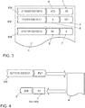
- a database is first created in a learning mode, with the following options, for example: For each reception pattern EM in a first time interval ⁇ t1, the data packets 9 are evaluated in the second time interval ⁇ t2. There are two counter readings 7, 8 (see 3 and 4 ), wherein one counter reading 7 is incremented for each successfully received data packet 9 and the other counter reading 8 is incremented for every data packet 9 not received. For example, if the second time interval ⁇ t2 is so long that theoretically six data packets 9 could be received and if four data packets 9 are received and two data packets 9 are not received, one counter reading 7 is increased by four and the other counter reading 8.
- the counter readings 7, 8 for more and more different reception patterns EM are available and the counter readings 7, 8 of the reception patterns EM increase continuously until a sufficient database is available.
- this is now shown schematically for part of the reception patterns EM, which are stored, for example, as a lookup table.
- the reception pattern EM "010111110010010” has a "3" for one counter reading 7 and a "34" for the other counter reading 8, ie that in previous measurements with a reception pattern EM "010111110010010” in the first time interval ⁇ t1 in the subsequent second time intervals ⁇ t2 a total of 3 data packets 9 were successfully received and 34 data packets 9 were not received.
- an anticipated reception quality can then be estimated in a time interval (with the length of the second time interval ⁇ t2), which will be explained later using Fig. 4 will be explained later.
- the database can be structured as follows. Again there is a counter reading 7 for successful and another counter reading 8 for unsuccessful data packets 9. The difference is that it is stipulated in advance that with n or more successful data packets 9 the one counter reading 7 increments in the second time interval ⁇ t2 and with less than n successful ones Data packets 9 the other counter 8 is incremented.
- the process of estimating the reception quality in a time interval is shown schematically, with ⁇ t1 in a preceding first time interval Receive pattern EM "101110110001101" was received.
- the estimated reception quality can also be expressed as a (success) probability P S (success probability).
- P S success probability
- the counter readings 7 and 8 are read out from the memory 4 for the reception pattern.
- P S states how great the probability is that a data packet 9 is received successfully or how great the probability is that n data packets or more are successfully received in the preceding time interval.
Landscapes
- Engineering & Computer Science (AREA)
- Computer Networks & Wireless Communication (AREA)
- Signal Processing (AREA)
- Physics & Mathematics (AREA)
- Electromagnetism (AREA)
- Quality & Reliability (AREA)
- Environmental & Geological Engineering (AREA)
- Health & Medical Sciences (AREA)
- Computing Systems (AREA)
- General Health & Medical Sciences (AREA)
- Medical Informatics (AREA)
- Mobile Radio Communication Systems (AREA)
Description
- Die Erfindung betrifft ein Verfahren und eine Vorrichtung zur Schätzung einer zu erwartenden Empfangsqualität in einem Zeitintervall für eine Car to X (C2X)-Kommunikation.
- Verkehrsunfälle und Straßenstaus sind erhebliche Probleme bei einer Fahrzeugfahrt. Fahrzeugad-hoc-Netz-basierte Systeme einer aktiven Steuerung und Fahrerunterstützung ermöglichen einem drahtlosen Nahbereichsfahrzeugkommunikationssystem, wie beispielsweise einem System einer dedizierten Nahbereichskommunikation (DSRC von dedicated short range communication) oder einem WiFi-basierten drahtlosen Kommunikationssystem, die Fachleuten bekannt sind, Nachrichten zu anderen Fahrzeugen zu übertragen. DSRC oder WiFi können verwendet werden, um drahtlose Fahrzeugmerkmale, die den Fahrerkomfort und die Fahrbahneffizienz verbessern können und viele Typen von fahrzeuginternen Diensten ermöglichen können, zu realisieren. Die DSRC-Technologie ermöglicht eine neue Klasse von Fahrzeugmerkmalen auf der Grundlage einer Kommunikation mit anderen Fahrzeugen (Car to Car bzw. C2C) oder der Infrastruktur (Car to Infrastructure bzw. C2I). Allgemein kann der Begriff (Car to X bzw. C2X) verwendet werden, um die verschiedenen Typen von Kommunikationsanwendungen zu bezeichnen, die durch DSRC und WiFi in Fahrzeugumgebungen ermöglicht werden.
- Aus der
DE 20 2011 011 487 A1 ist ein Verfahren zum Optimieren von Daten, die zwischen Fahrzeugen transferiert werden, bekannt. Dabei wird ermittelt, ob es verlorene Pakete in einer Sequenz von Statusnachrichten gibt, die zwischen zwei Fahrzeugen übertragen werden. Es wird ermittelt, ob eine Anzahl an erfolgreichen Pakettransfers größer oder gleich einem Schwellenwert für erfolgreiche Pakete ist und ob sich eine Angabe der empfangenen Signalstärke erhöht, wenn es keine verlorenen Pakete in der Sequenz von Nachrichten gibt. Es wird ermittelt, ob eine Anzahl an verlorenen Pakettransfers größer oder gleich einem Schwellenwert für verlorene Pakete ist und ob sich eine Angabe der empfangenen Signalstärke verringert, wenn es keine verlorenen Pakete in der Sequenz von Nachrichten gibt. Es wird ermittelt, ob eine Anzahl an verlorenen Pakettransfers größer oder gleich dem Schwellenwert für erfolgreiche Pakete ist und wenn sich die Angabe der empfangenen Signalstärke erhöht. Die Länge des Nachrichtenpakets wird um einen vorbestimmten Paketverringerungsumfang verringert, wenn die Anzahl an verlorenen Pakettransfers größer oder gleich dem Schwellenwert für erfolgreiche Pakete ist und wenn sich die Angabe der empfangenen Signalstärke verringert. - Ein ähnliches Verfahren ist aus der
US 7,355,997 B2 bekannt. - Aus Gietelink O. J. et al.: "A probabilistic approach for validation of advanced driver assistance systems", Transportation Research Record, Transportation Research Board, Washington, DC. US, Nr. Technical report 04-016, 1. November 2004 (2004-11-01), Seiten 1-18, XP007911731, ISSN: 0361-1981 ist ein Verfahren bekannt, das zur Validierung von Fahrerassistenzsystemen eine empirisch bestimmte Wahrscheinlichkeit verwendet, die sich aus dem Mittelwert von N unabhängigen und gleichverteilten Experimenten einer Indikatorfunktion berechnet, um beispielsweise Kollisionswahrscheinlichkeiten zu bestimmen.
- Aus der
DE 10 2009 054 795 A1 ist ein Kommunikationssystem für ein Fahrzeug bekannt, das ein mobiles Kommunikationsmodul aufweist, wobei das Kommunikationssystem zum Senden von Fahrzeug-zu-X-Botschaften an ein benachbartes Fahrzeug oder zum Empfangen von Fahrzeug-zu-X-Botschaften von einem benachbarten Fahrzeug ausgeführt ist, wobei zumindest ein Teil des mobilen Kommunikationsmoduls zum Beitragen an der Bereitstellung der Kommunikation mit dem benachbarten Fahrzeug vorgesehen ist. Dabei ist weiter vorgesehen, dass das mobile Kommunikationsmodul zur Bestimmung einer Position des Fahrzeugs ausgeführt ist, wobei das Kommunikationssystem zur Integration der von dem mobilen Kommunikationsmodul bestimmten Position in die zu sendenden Botschaften ausgeführt ist und/oder dass das Kommunikationssystem zur Verifizierung einer von dem Fahrzeug bestimmten Position auf Basis der von dem mobilen Kommunikationsmodul bestimmten Position ausgeführt ist. - Nachteilig ist, dass diese Verfahren erst auf eine verschlechterte Empfangssituation reagieren. Insbesondere im Falle, wo die C2X Nachrichten zur Unterstützung einer Assistenz-Funktion in einem Kraftfahrzeug dienen, wird dann der Nutzer gegebenenfalls überrascht, wenn die Assistenz-Funktion aufgrund der verschlechterten Empfangssituation nur eingeschränkt funktionsfähig ist.
- Der Erfindung liegt das technische Problem zugrunde, ein Verfahren bereitzustellen sowie eine Vorrichtung zu schaffen, mittels derer eine zu erwartende Empfangsqualität geschätzt werden kann.
- Die Erfindung wird in den angehängten Ansprüchen definiert.
- Das Verfahren zur Schätzung einer zu erwartenden Empfangsqualität in einem Zeitintervall für Car to X (C2X)-Kommunikation erfolgt mittels eines Speichers. In dem Speicher ist mindestens eine empirisch ermittelte Größe zu Empfangsmustern von Datenpaketen in einem ersten Zeitintervall abgelegt, wobei die Größe angibt oder aus der Größe ermittelbar ist, wie groß die Wahrscheinlichkeit ist, dass in einem nachfolgenden zweiten Zeitintervall ein Datenpaket oder n Datenpakete erfolgreich empfangen werden. Die Empfangsmuster sind dabei vorzugsweise binäre Muster, die beispielsweise eine logische 1 für ein erfolgreich empfangenes Datenpaket aufweisen und eine logische 0 für ein nicht erfolgreich empfangenes Datenpaket aufweisen. Die Länge des ersten Zeitintervalls, des zweiten Zeitintervalls und der Größe n sind dabei freiparametrierbar. Allerdings gilt, dass vorzugsweise das erste Zeitintervall länger als das zweite Zeitintervall ist. Des Weiteren wird n in Abhängigkeit der Länge des zweiten Zeitintervalls gewählt. Dabei ist n eine natürliche Zahl und kann daher auch 1 sein. Der Grundgedanke der Erfindung ist dabei, dass zumindest eine gewisse Korrelation zwischen einem Empfangsmuster im ersten Zeitintervall mit einem Empfangsmuster im zweiten Zeitintervall vorliegt, sodass das erste Zeitintervall Rückschlüsse auf das zweite Zeitintervall erlaubt.
- Die Datenbasis in dem Speicher wird hierzu empirisch in einer Vorstufe ermittelt. Existiert dann eine Datenbasis, die vorzugsweise zu jedem oder sehr vielen Empfangsmuster eine Größe hat, kann das eigentliche Verfahren beginnen. Für Empfangsmuster, wo noch keine Größe existiert, kann dabei vorgesehen sein, dass ein geeigneter Mittelwert (Median oder arithmetischer Mittelwert) für die Größe angesetzt wird. Weiter kann vorgesehen sein, dass die Empfangsgüte des Musters selbst herangezogen wird. So werden beispielsweise die logischen 1en ins Verhältnis zur Bitzahl des Empfangsmusters gesetzt. Ein Empfangsmuster 0100 hätte dann eine Empfangswahrscheinlichkeit von 25 %.
- Soll nun die Empfangsqualität für ein zukünftiges Zeitintervall mit der Länge der zweiten Zeitintervalle geschätzt werden, so wird für ein erstes Zeitintervall vor dem zukünftigen Zeitintervall das Empfangsmuster bestimmt. Aus dem Speicher wird dann die zugehörige Größe für die Wahrscheinlichkeit für das Zeitintervall aufgrund des vorangegangenen Empfangsmusters ausgelesen, wobei in Abhängigkeit der Wahrscheinlichkeit eine Warnmeldung generiert wird und/oder ein Übertragungsparameter und/oder eine Funktionalität einer Fahrerassistenzfunktion verändert wird. Beispielsweise kann einer sendenden Infrastruktur oder einem sendenden Fahrzeug mitgeteilt werden, dass die Sendeleistung erhöht und/oder eine Sendefrequenz verändert wird (z.B. erhöht wird) oder eine Paketlänge reduziert werden soll. Die Änderung der Funktionalität einer Fahrerassistenzfunktion kann beispielsweise darin bestehen, dass diese nur mit eingeschränktem Leistungsumfang oder im Extremfall gar nicht angeboten wird. Durch die Schätzung der zu erwartenden Empfangsqualität wird der Nutzer (Fahrer) frühzeitig auf gegebenenfalls zu erwartende Einschränkungen aufgrund der mangelnden Empfangsqualität hingewiesen, sodass dieser sich entsprechend darauf einstellen kann. Ein Schwellwert für die Wahrscheinlichkeit, bei deren Unterschreitung eine Warnmeldung generiert wird, kann dabei abhängig von der Anwendung gewählt werden.
- In einer Ausführungsform werden die Anzahl der erfolgreich empfangenen Datenpakete und/oder nicht erfolgreich empfangenen Datenpakete in dem Zeitintervall erfasst, wobei die Wahrscheinlichkeit für das Empfangsmuster in dem Speicher aufgrund der erfassten Empfangsqualität aktualisiert wird. D.h. die Datenbasis wird fortlaufend aktualisiert und ist quasi selbstlernend. Hierdurch findet automatisch eine Anpassung an sich ändernde Umstände statt, beispielsweise wenn der Fahrer nach längerer Zeit von Fahrten auf Landstraßen auf Autobahnfahrt wechselt und umgekehrt.
- In einer Ausführungsform existieren in dem Speicher zu jedem Empfangsmuster zwei Zählerstände, wobei der eine Zählerstand inkrementiert wird, wenn n oder mehr Datenpakete im Zeitintervall erfolgreich empfangen wurden und der andere Zählerstand inkrementiert wird, wenn weniger als n Datenpakete im Zeitintervall erfolgreich empfangen wurden. Dies stellt eine qualitative Bewertung dar. Beispielsweise hat das Zeitintervall eine Länge, um fünf Datenpakete zu empfangen, wobei n = 3 sei. Dann wird bei 3, 4 oder 5 erfolgreich empfangenen Datenpaketen der eine Zähler inkrementiert. D.h. die Zählerstände bzw. deren Verhältnis zueinander geben die Wahrscheinlichkeit an, ob n oder mehr Datenpakete erfolgreich empfangen werden. Dabei sei angemerkt, dass es auch möglich ist, mit einem Zähler zu arbeiten, der inkrementiert und dekrementiert wird, solange nur Überläufe beobachtet werden. Alternativ kann die Inkrementierung auch qualitativ erfolgen, indem der eine Zähler entsprechend der Anzahl der erfolgreich empfangenen Datenpakete im Zeitintervall inkrementiert wird und entsprechend der andere Zähler entsprechend der Anzahl nicht erfolgreich empfangener Datenpakete inkrementiert wird. Dabei sei angemerkt, dass in vorgegebenen Zeitabständen der Speicher bzw. der oder die Zählerstände gelöscht bzw. zurückgesetzt werden können. Die vorgegebene Zeit ist dabei vorzugsweise freiparametrierbar.
- In einer Ausführungsform ist das erste Zeitintervall ein Vielfaches größer als das zweite Zeitintervall, was bezüglich der Korrelation von Vorteil ist.
- In einer weiteren Ausführungsform ist in dem Speicher für die Empfangsmuster in Abhängigkeit von mindestens einem Parameter eine verschiedene Größe der Wahrscheinlichkeit abgelegt, wobei die zugehörige Größe oder Wahrscheinlichkeit automatisch in Abhängigkeit des Parameters ausgewählt wird oder der Parameter manuell ausgewählt wird. Der oder die Parameter können beispielsweise Umgebungsparameter wie Stadt, Autobahn, Waldgebiete oder auch Wochentage sein, die einen Einfluss auf die Empfangsqualität haben können. Dies erlaubt eine noch bessere Schätzung der zu erwartenden Empfangsqualität. Die automatische Erkennung des Parameters kann beispielsweise mittels Navigationsdaten oder Daten eines Bordcomputers erfolgen.
- Die Vorrichtung zur Schätzung einer zu erwartenden Empfangsqualität in einem Zeitintervall für C2X-Kommunikation umfasst eine Empfangseinrichtung zur Erfassung von Datenpaketen und einen Speicher. In dem Speicher ist zu Empfangsmustern von Datenpaketen in einem ersten Zeitintervall mindestens eine empirisch ermittelte Größe abgelegt, die angibt oder aus der ermittelbar ist, wie groß die Wahrscheinlichkeit ist, dass in einem nachfolgenden zweiten Zeitintervall ein Datenpaket oder n Datenpakete erfolgreich empfangen werden. Die Vorrichtung ist dabei derart ausgebildet, dass für ein erstes Zeitintervall vor dem Zeitintervall das Empfangsmuster bestimmt und die zugehörige Wahrscheinlichkeit für das Zeitintervall aus dem Speicher ausgelesen wird, wobei in Abhängigkeit der Wahrscheinlichkeit eine Warnmeldung generiert und/oder ein Übertragungsparameter und/oder eine Funktionalität einer Fahrerassistenzfunktion verändert wird. Hinsichtlich der weiteren vorteilhaften Ausgestaltungen der Vorrichtung wird auf die vorangegangenen Ausführungen zum Verfahren vollinhaltlich Bezug genommen.
- Die Erfindung wird nachfolgend anhand eines bevorzugten Ausführungsbeispiels näher erläutert. Die Figuren zeigen:
- Fig. 1
- ein schematisches Blockschaltbild einer Vorrichtung zur Schätzung einer zu erwartenden Empfangsqualität,
- Fig. 2
- eine schematische Darstellung eines Empfangsmusters,
- Fig. 3
- eine schematische Teilansicht einer Lookup-Tabelle nach einem Lernmodus und
- Fig. 4
- eine schematische Darstellung des Ablaufs zur Schätzung einer zu erwartenden Empfangsqualität.
- In der
Fig. 1 ist ein Blockschaltbild einer Vorrichtung 1 zur Schätzung einer zu erwartenden Empfangsqualität in einem Zeitintervall für C2X-Kommunikation dargestellt, die eine Empfangseinrichtung 2, eine Steuereinheit 3, einen Speicher 4 und eine Anzeigeeinheit 5 aufweist. Die Empfangseinrichtung 2 ist dabei typischerweise als Sende- und Empfangseinrichtung ausgebildet, wobei hier jedoch nur die Empfangseinrichtung 2 von Interesse ist. Die empfangenen und nicht empfangenen Datenpakete 6 (sieheFig. 2 ) werden an die Steuereinheit 3 übermittelt, wo diese ausgewertet werden und Anwendungen zur Verfügung gestellt werden. Dabei kann die Steuereinheit 3 mit Hilfe der in dem Speicher 4 abgelegten Größen für Empfangsmuster EM (sieheFig. 2 ) die zu erwartende Empfangsqualität schätzen. Unterschreitet dann die geschätzte Empfangsqualität einen Schwellwert, so wird auf der Anzeigeeinheit 5 eine Warnmeldung angezeigt. Dabei sind alternativ oder zusätzlich weitere Warnformen wie akustisch und/oder haptisch möglich. Alternativ oder zusätzlich kann eine Funktionalität einer Fahrerassistenzfunktion verändert werden, beispielsweise deren Funktionsumfang beschränkt werden. - Zunächst soll der Inhalt des Speichers anhand der
Fig. 2 und3 näher erläutert werden. InFig. 2 ist ein Empfangsmuster EM für ein erstes Zeitintervall Δt1 = t0 - tstart dargestellt, wie es beispielsweise von der Empfangseinrichtung 2 empfangen wird. Abhängig von der Sendefrequenz wird dann das erste Zeitintervall Δt1 in Zeitschlitze unterteilt und geschaut, ob in dem Zeitschlitz ein Datenpaket 6 empfangen wird oder nicht. Das Empfangsmuster EM ist ein binäres Muster mit einer logischen 1, wenn ein Datenpaket 6 erfolgreich empfangen wurde, und einer logischen 0, wenn ein Datenpaket 6 nicht erfolgreich empfangen wurde. Zur Veranschaulichung sind oberhalb der logischen 1 en piktogrammförmige Datenpakete 6 dargestellt. Die Vorrichtung soll nun schätzen, wie die zu erwartende Empfangsqualität in einem nachfolgenden zweiten Zeitintervall Δt2 = tafter - t0 für Datenpakete 9 ist. - Hierzu wird in einem Lernmodus zunächst eine Datenbasis angelegt, wobei hierzu beispielsweise folgende Möglichkeiten bestehen:
Zu jedem Empfangsmuster EM in einem ersten Zeitintervall Δt1 werden die Datenpakete 9 im zweiten Zeitintervall Δt2 ausgewertet. Dabei existieren zwei Zählerstände 7, 8 (sieheFig. 3 und 4 ), wobei der eine Zählerstand 7 bei jedem erfolgreich empfangenen Datenpaket 9 inkrementiert wird und der andere Zählerstand 8 bei jedem nicht empfangenen Datenpaket 9 inkrementiert wird. Ist beispielsweise das zweite Zeitintervall Δt2 so lang, dass theoretisch sechs Datenpakete 9 empfangen werden könnten und werden vier Datenpakete 9 empfangen und zwei Datenpakete 9 nicht empfangen, so wird der eine Zählerstand 7 vier und der andere Zählerstand 8 um zwei erhöht. Mit der Zeit liegen dann Zählerstände 7, 8 für immer mehr verschiedene Empfangsmuster EM vor und die Zählerstände 7, 8 der Empfangsmuster EM erhöhen sich kontinuierlich, bis eine ausreichende Datenbasis vorliegt. In derFig. 3 ist dies nun schematisch für einen Teil der Empfangsmuster EM dargestellt, die beispielsweise als Lookup-Tabelle abgelegt sind. - Das Empfangsmuster EM "010111110010010" hat dabei für den einen Zählerstand 7 eine "3" und für den anderen Zählerstand 8 eine "34", d.h. dass in vorangegangenen Messungen mit einem Empfangsmuster EM "010111110010010" in dem ersten Zeitintervall Δt1 in den nachfolgenden zweiten Zeitintervallen Δt2 insgesamt 3 Datenpakete 9 erfolgreich empfangen wurden und 34 Datenpakete 9 nicht empfangen wurden. Anhand dieser Zählerstände 7, 8 kann dann eine zu erwartende Empfangsqualität in einem Zeitintervall (mit der Länge des zweiten Zeitintervalls Δt2) geschätzt werden, was später anhand von
Fig. 4 noch erläutert wird. - Alternativ kann die Datenbasis wie folgt aufgebaut werden. Wieder existiert ein Zählerstand 7 für erfolgreiche und ein anderer Zählerstand 8 für nicht erfolgreiche Datenpakete 9. Der Unterschied ist, dass vorab festgelegt wird, dass bei n oder mehr erfolgreichen Datenpaketen 9 im zweiten Zeitintervall Δt2 der eine Zählerstand 7 inkrementiert und bei weniger als n erfolgreichen Datenpaketen 9 der andere Zählerstand 8 inkrementiert wird.
- In der
Fig. 4 ist nun schematisch der Vorgang der Schätzung der Empfangsqualität in einem Zeitintervall dargestellt, wobei in einem vorangegangenen ersten Zeitintervall Δt1 ein Empfangsmuster EM "101110110001101" empfangen wurde. Die geschätzte Empfangsqualität kann auch als (Erfolgs)-Wahrscheinlichkeit PS (success probability) ausgedrückt werden. Hierzu werden die Zählerstände 7 und 8 aus dem Speicher 4 für das Empfangsmuster ausgelesen. Die Wahrscheinlichkeit PS ist dann im dargestellten Zahlenbeispiel
- Je nachdem wie die Zählerstände zuvor gebildet wurden, sagt PS aus, wie groß die Wahrscheinlichkeit ist, dass ein Datenpaket 9 erfolgreich empfangen wird oder wie groß die Wahrscheinlichkeit ist, dass n Datenpakete oder mehr im vorausliegenden Zeitintervall erfolgreich empfangen werden.
Claims (10)
- Verfahren zur Schätzung einer zu erwartenden Empfangsqualität in einem Zeitintervall (Δt2) für eine Car to X, C2X, Kommunikation mittels eines Speichers (4), wobei in dem Speicher (4) zu binären Empfangsmustern, EM, von Datenpaketen (6) in einem ersten Zeitintervall (Δt1) mindestens eine empirisch ermittelte Größe abgelegt ist, die angibt oder aus der ermittelbar ist, wie groß die Wahrscheinlichkeit, Ps, ist, dass in einem nachfolgenden zweiten Zeitintervall (Δt2) ein Datenpaket (9) oder n Datenpakete (9) erfolgreich empfangen werden, wobei das binäre Empfangsmuster, EM, eine logische 1 für ein erfolgreich empfangenes Datenpaket (6) und eine logische 0 für ein nicht erfolgreich empfangenes Datenpaket aufweist, wobei für ein erstes Zeitintervall (Δt1) vor dem Zeitintervall das binäre Empfangsmuster, EM, bestimmt und die zugehörige Größe für die Wahrscheinlichkeit, Ps, für das Zeitintervall (Δt2) aus dem Speicher (4) ausgelesen wird, wobei in Abhängigkeit der Wahrscheinlichkeit, Ps, eine Warnmeldung generiert wird und/oder ein Übertragungsparameter und/oder eine Funktionalität einer Fahrerassistenzfunktion verändert wird.
- Verfahren nach Anspruch 1, dadurch gekennzeichnet, dass die Anzahl der erfolgreich empfangenen Datenpakete (9) und/oder nicht erfolgreich empfangenen Datenpakete (9) in dem Zeitintervall (Δt2) erfasst werden, wobei die Größe oder die Wahrscheinlichkeit (PS) für das binäre Empfangsmuster, EM, in dem Speicher (4) aufgrund der erfassten Empfangsqualität aktualisiert wird.
- Verfahren nach Anspruch 1 oder 2, dadurch gekennzeichnet, dass in dem Speicher (4) zu jedem binären Empfangsmuster, EM, zwei Zählerstände (7, 8) existieren, wobei der eine Zählerstand (7) inkrementiert wird, wenn n oder mehr Datenpakete (9) im Zeitintervall (Δt2) erfolgreich empfangen wurden und der andere Zählerstand (8) inkrementiert wird, wenn weniger als n Datenpakete (9) im Zeitintervall (Δt2) erfolgreich empfangen wurden, oder der eine Zählerstand (7) inkrementiert wird, wenn jeweils ein Datenpaket (9) erfolgreich empfangen wurde und der andere Zählerstand (8) inkrementiert wird, wenn jeweils ein Datenpaket (9) nicht erfolgreich empfangen wurde.
- Verfahren nach einem der vorangegangenen Ansprüche, dadurch gekennzeichnet, dass das erste Zeitintervall (Δt1) ein Vielfaches größer als das zweite Zeitintervall (Δt2) gewählt wird.
- Verfahren nach einem der vorangegangenen Ansprüche, dadurch gekennzeichnet, dass in dem Speicher (4) für die binären Empfangsmuster, EM, in Abhängigkeit von mindestens einem weiteren Parameter eine zugehörige Größe oder Wahrscheinlichkeit, Ps, abgelegt ist, wobei die zugehörige Größe oder Wahrscheinlichkeit, Ps, automatisch in Abhängigkeit des weiteren Parameters ausgewählt wird oder der weitere Parameter manuell ausgewählt wird.
- Vorrichtung (1) zur Schätzung einer zu erwartenden Empfangsqualität in einem Zeitintervall (Δt2) für eine Car to X, C2X, Kommunikation, umfassend eine Empfangseinrichtung (2) zur Erfassung von Datenpaketen (6, 9) und einem Speicher (4), wobei in dem Speicher (4) zu binären Empfangsmustern, EM, von Datenpaketen (6) in einem ersten Zeitintervall (Δt1) mindestens eine empirisch ermittelte Größe abgelegt ist, die angibt oder aus der ermittelbar ist, wie groß die Wahrscheinlichkeit, Ps, ist, dass in einem nachfolgenden zweiten Zeitintervall (Δt2) ein Datenpaket (9) oder n Datenpakete (9) erfolgreich empfangen werden, wobei das binäre Empfangsmuster, EM, eine logische 1 für ein erfolgreich empfangenes Datenpaket (6) und eine logische 0 für ein nicht erfolgreich empfangenes Datenpaket aufweist, wobei die Vorrichtung (1) derart ausgebildet ist, dass für ein erstes Zeitintervall (Δt1) vor dem Zeitintervall (Δt2) das binäre Empfangsmuster, EM, bestimmt und die zugehörige Größe für die Wahrscheinlichkeit, Ps, für das Zeitintervall (Δt2) aus dem Speicher (4) ausgelesen wird, wobei in Abhängigkeit der Wahrscheinlichkeit, Ps, eine Warnmeldung generiert und/oder ein Übertragungsparameter und/oder eine Funktionalität einer Fahrerassistenzfunktion verändert wird.
- Vorrichtung nach Anspruch 6, dadurch gekennzeichnet, dass die Vorrichtung (1) derart ausgebildet ist, dass die Anzahl der erfolgreich empfangenen Datenpakete (9) und/oder nicht erfolgreich empfangenen Datenpakete (9) in dem Zeitintervall (Δt2) erfasst werden, wobei die Größe oder die Wahrscheinlichkeit, Ps, in dem Speicher (4) für das binäre Empfangsmuster, EM, aufgrund der erfassten Empfangsqualität aktualisiert wird.
- Vorrichtung nach einem der Ansprüche 6 oder 7, dadurch gekennzeichnet, dass die Vorrichtung (1) derart ausgebildet ist, dass in dem Speicher (4) zu jedem binären Empfangsmuster, EM, zwei Zählerstände (7, 8) existieren, wobei der eine Zählerstand (7) inkrementiert wird, wenn n oder mehr Datenpakete (9) im Zeitintervall (Δt2) erfolgreich empfangen wurden und der andere Zählerstand (8) inkrementiert wird, wenn weniger als n Datenpakete (9) im Zeitintervall (Δt2) erfolgreich empfangen wurden, oder der eine Zählerstand (7) inkrementiert wird, wenn jeweils ein Datenpaket (9) erfolgreich empfangen wurde und der andere Zählerstand (8) inkrementiert wird, wenn jeweils ein Datenpaket (9) nicht erfolgreich empfangen wurde.
- Vorrichtung nach einem der Ansprüche 6 bis 8, dadurch gekennzeichnet, dass das erste Zeitintervall (Δt1) ein Vielfaches größer als das zweite Zeitintervall (Δt2) ist.
- Vorrichtung nach einem der Ansprüche 6 bis 9, dadurch gekennzeichnet, dass in dem Speicher (4) für die binären Empfangsmuster, EM, in Abhängigkeit von mindestens einem weiteren Parameter eine zugehörige Größe oder Wahrscheinlichkeit, Ps, abgelegt ist, wobei die Vorrichtung (1) derart ausgebildet ist, dass die zugehörige Größe oder Wahrscheinlichkeit, Ps, automatisch in Abhängigkeit des Parameters ausgewählt wird oder der Parameter manuell ausgewählt wird.
Applications Claiming Priority (2)
| Application Number | Priority Date | Filing Date | Title |
|---|---|---|---|
| DE102014208500.4A DE102014208500A1 (de) | 2014-05-07 | 2014-05-07 | Verfahren und Vorrichtung zur Schätzung einer zu erwartenden Empfangsqualität |
| PCT/EP2015/057318 WO2015169516A1 (de) | 2014-05-07 | 2015-04-02 | Verfahren und vorrichtung zur schätzung einer zu erwartenden empfangsqualität |
Publications (2)
| Publication Number | Publication Date |
|---|---|
| EP3141014A1 EP3141014A1 (de) | 2017-03-15 |
| EP3141014B1 true EP3141014B1 (de) | 2019-12-25 |
Family
ID=53724288
Family Applications (1)
| Application Number | Title | Priority Date | Filing Date |
|---|---|---|---|
| EP15741910.2A Active EP3141014B1 (de) | 2014-05-07 | 2015-04-02 | Verfahren und vorrichtung zur schätzung einer zu erwartenden empfangsqualität |
Country Status (5)
| Country | Link |
|---|---|
| US (1) | US10193641B2 (de) |
| EP (1) | EP3141014B1 (de) |
| CN (1) | CN106465153B (de) |
| DE (1) | DE102014208500A1 (de) |
| WO (1) | WO2015169516A1 (de) |
Families Citing this family (3)
| Publication number | Priority date | Publication date | Assignee | Title |
|---|---|---|---|---|
| US11375437B2 (en) * | 2015-10-07 | 2022-06-28 | Time Warner Cable Enterprises Llc | Management frames and usage in a wireless network environment |
| US10571687B2 (en) * | 2018-02-05 | 2020-02-25 | Goodrich Corporation | Imaging systems and methods |
| CN114745339B (zh) * | 2022-04-07 | 2023-10-20 | 潍柴动力股份有限公司 | 多包报文数据的传输方法、传输装置和传输系统 |
Family Cites Families (19)
| Publication number | Priority date | Publication date | Assignee | Title |
|---|---|---|---|---|
| CA2293606C (en) * | 1998-04-17 | 2005-02-08 | Matsushita Electric Industrial Co., Ltd. | Radio communication apparatus and transmission rate control method |
| US6097697A (en) * | 1998-07-17 | 2000-08-01 | Sitara Networks, Inc. | Congestion control |
| JP2005186813A (ja) * | 2003-12-25 | 2005-07-14 | Fuji Heavy Ind Ltd | 車両用運転支援装置 |
| US7355997B2 (en) | 2004-05-07 | 2008-04-08 | Cisco Technology, Inc. | Data rate shifting methods and techniques |
| WO2008148106A1 (en) * | 2007-05-25 | 2008-12-04 | New Jersey Institute Of Technology | Proactive test-based differentiation method and system to mitigate low rate dos attacks |
| US7839793B2 (en) | 2007-11-20 | 2010-11-23 | Siemens Enterprise Communications Gmbh & Co. Kg | Method and apparatus for estimating collision probability in a wireless network |
| JP4924503B2 (ja) * | 2008-03-25 | 2012-04-25 | 富士通株式会社 | 輻輳検出方法、輻輳検出装置及び輻輳検出プログラム |
| JP2010183178A (ja) * | 2009-02-03 | 2010-08-19 | Denso Corp | 車載通信装置 |
| DE102009054795A1 (de) | 2009-03-20 | 2010-09-23 | Continental Teves Ag & Co. Ohg | Fahrzeug-zu-X Kommunikation über mobile Geräte, die mit dem Fahrzeug verbunden sind |
| CN102792756A (zh) * | 2010-01-14 | 2012-11-21 | 爱信精机株式会社 | 节点、通信系统、程序以及通信方法 |
| US8300564B2 (en) | 2010-02-25 | 2012-10-30 | GM Global Technology Operations LLC | Opportunistic data transfer between vehicles |
| US20110238259A1 (en) * | 2010-03-25 | 2011-09-29 | Gm Global Technology Operations, Inc. | V2X-Connected Cooperative Diagnostic & Prognostic Applications in Vehicular AD HOC Networks |
| DE102011010846B4 (de) | 2011-02-10 | 2014-02-06 | Audi Ag | Verfahren und System zur sichtverbindungsunabhängigen Datenübertragung |
| US8756430B2 (en) * | 2011-04-14 | 2014-06-17 | GM Global Technology Operations LLC | Exploiting application characteristics for multiple-authenticator broadcast authentication schemes |
| CN102497614B (zh) * | 2011-12-12 | 2014-03-12 | 吉林大学 | 车辆间行驶状态数据无线通信控制器及其控制方法 |
| US8704679B2 (en) * | 2012-06-27 | 2014-04-22 | GM Global Technology Operations LLC | Framework for packet processing for secure V2V applications on resource-constrained platforms |
| JP5958325B2 (ja) * | 2012-12-20 | 2016-07-27 | 富士通株式会社 | ネットワーク分析方法、情報処理装置およびプログラム |
| CN103501506B (zh) * | 2013-05-17 | 2018-07-27 | 北京九五智驾信息技术股份有限公司 | 一种车联网服务的终端自适应数据传输系统和方法 |
| US20150023668A1 (en) * | 2013-07-22 | 2015-01-22 | Osram Sylvania Inc. | Light-based communications utilizing a gossip network in a vehicle/roadway environment |
-
2014
- 2014-05-07 DE DE102014208500.4A patent/DE102014208500A1/de not_active Withdrawn
-
2015
- 2015-04-02 US US15/330,868 patent/US10193641B2/en active Active
- 2015-04-02 CN CN201580035102.XA patent/CN106465153B/zh active Active
- 2015-04-02 WO PCT/EP2015/057318 patent/WO2015169516A1/de not_active Ceased
- 2015-04-02 EP EP15741910.2A patent/EP3141014B1/de active Active
Non-Patent Citations (1)
| Title |
|---|
| None * |
Also Published As
| Publication number | Publication date |
|---|---|
| US10193641B2 (en) | 2019-01-29 |
| DE102014208500A1 (de) | 2015-11-12 |
| CN106465153A (zh) | 2017-02-22 |
| EP3141014A1 (de) | 2017-03-15 |
| US20170250763A1 (en) | 2017-08-31 |
| WO2015169516A1 (de) | 2015-11-12 |
| CN106465153B (zh) | 2020-10-13 |
Similar Documents
| Publication | Publication Date | Title |
|---|---|---|
| DE102019108083B4 (de) | Verkehrszeichenerkennung für vernetzte Fahrzeuge | |
| EP3350792B1 (de) | Vorrichtung, verfahren und computerprogramm zum bereitstellen von information über ein stauende über eine fahrzeug-zu-fahrzeug-schnittstelle | |
| DE102016211750B4 (de) | Verfahren zur spektral-effizienten Ermittlung von kollektiver Umfeld-Information für das kooperative und/oder autonome Fahren, sowie berichtendes Fahrzeug und weiteres Fahrzeug zur Verwendung bei dem Verfahren | |
| EP2894616B1 (de) | Onboard-Unit und Verfahren zur Information eines Fahrers | |
| DE102010038640A1 (de) | Vorrichtung und Verfahren zur C2X-Kommunikation | |
| EP2756491B1 (de) | Verfahren und vorrichtung zum bestimmen einer fahrempfehlung für ein fahrzeug sowie verfahren und vorrichtung zum bereitstellen einer fahrempfehlung für ein fahrzeug | |
| DE102009008959A1 (de) | Fahrzeugsystem zur Navigation und/oder Fahrerassistenz | |
| DE102016205140A1 (de) | Verfahren und Regelungssysteme zur Bestimmung einer Verkehrslücke zwischen zwei Fahrzeugen für einen Fahrstreifenwechsel für ein Fahrzeug | |
| EP2601481A1 (de) | Verfahren zur unterstützung eines einparkvorgangs in einem parkhaus, einparksystem für ein fahrzeug und belegungszustandserkennungssystem für ein parkhaus | |
| DE202013006466U1 (de) | Computerprogrammprodukt und Fahrerassistenzsystem für einFahrzeug | |
| EP2953111A1 (de) | Verfahren und Vorrichtung zur Ermittlung freier Abstellplätze auf LKW-Parkplätzen und Mitteilung an LKW-Fahrer | |
| DE102007042877A1 (de) | Kraftfahrzeug und System zur Vermittlung von Fahrbahneigenschaftsinformationen | |
| DE102010029073A1 (de) | Einrichtung und Verfahren zur Zuordnung von neuen Daten zu einer digitalen Karte | |
| DE102021209134A1 (de) | Verfahren und Vorrichtung zur Validierung von Fahrzeug-zu-X Nachrichten zur Regelung des Verkehrsflusses | |
| DE102009007350A1 (de) | Fahrzeug-Fahrzeug-Kommunikationsvorrichtung und Fahrzeug-Fahrzeug-Kommunikationsverfahren | |
| EP3141014B1 (de) | Verfahren und vorrichtung zur schätzung einer zu erwartenden empfangsqualität | |
| DE102014202509B4 (de) | Steuerung einer hoch- oder vollautomatischen Fahrfunktion | |
| DE102019001092A1 (de) | Verfahren zum Betreiben eines Fahrerassistenzsystems, sowie elektronische Recheneinrichtung, Computerprogrammprodukt und Datenträger | |
| DE102014226223B4 (de) | Regelbasiertes Interaktionsverfahren für ein Kraftfahrzeug mit dessen Umgebung | |
| EP3994902B1 (de) | Verfahren zur kooperativen ressourcenallokation zum ausführen von bewegungsmanövern in einem strassenbereich sowie zugehörige steuerschaltung und kraftfahrzeug mit einer solchen steuerschaltung | |
| DE102007027651A1 (de) | Sicherheitssystem für ein Kraftfahrzeug und Verfahren zum Betreiben des Sicherheitssystems, ortfeste Kommunikationsvorrichtung und Verfahren zum Betreiben der ortfesten Kommunikationsvorrichtung | |
| DE102018216867B4 (de) | Verfahren zur Ermittlung eines Standorts für ein Kraftfahrzeug für eine verbesserte Empfangsqualität und Kraftfahrzeug | |
| EP3389291A1 (de) | Kommunikation zwischen einem fahrzeug und mehreren roadside units | |
| DE112017005195T5 (de) | Vorrichtung und Verfahren zum Bestimmen von folgenden Fahrzeuginformationen | |
| EP2212877B1 (de) | Lokalisierungsverfahren |
Legal Events
| Date | Code | Title | Description |
|---|---|---|---|
| STAA | Information on the status of an ep patent application or granted ep patent |
Free format text: STATUS: THE INTERNATIONAL PUBLICATION HAS BEEN MADE |
|
| PUAI | Public reference made under article 153(3) epc to a published international application that has entered the european phase |
Free format text: ORIGINAL CODE: 0009012 |
|
| STAA | Information on the status of an ep patent application or granted ep patent |
Free format text: STATUS: REQUEST FOR EXAMINATION WAS MADE |
|
| 17P | Request for examination filed |
Effective date: 20161207 |
|
| AK | Designated contracting states |
Kind code of ref document: A1 Designated state(s): AL AT BE BG CH CY CZ DE DK EE ES FI FR GB GR HR HU IE IS IT LI LT LU LV MC MK MT NL NO PL PT RO RS SE SI SK SM TR |
|
| AX | Request for extension of the european patent |
Extension state: BA ME |
|
| RIN1 | Information on inventor provided before grant (corrected) |
Inventor name: SIMSEK, BURAK Inventor name: AYMELEC, TETIANA DR. Inventor name: MEIER, JAN-NIKLAS |
|
| DAV | Request for validation of the european patent (deleted) | ||
| DAX | Request for extension of the european patent (deleted) | ||
| GRAP | Despatch of communication of intention to grant a patent |
Free format text: ORIGINAL CODE: EPIDOSNIGR1 |
|
| STAA | Information on the status of an ep patent application or granted ep patent |
Free format text: STATUS: GRANT OF PATENT IS INTENDED |
|
| RIC1 | Information provided on ipc code assigned before grant |
Ipc: H04L 12/24 20060101ALN20190611BHEP Ipc: H04W 84/18 20090101ALN20190611BHEP Ipc: H04L 12/26 20060101ALN20190611BHEP Ipc: H04B 17/23 20150101ALN20190611BHEP Ipc: H04W 24/00 20090101AFI20190611BHEP Ipc: H04L 29/08 20060101ALN20190611BHEP Ipc: H04B 17/373 20150101ALI20190611BHEP |
|
| RIC1 | Information provided on ipc code assigned before grant |
Ipc: H04L 12/26 20060101ALN20190618BHEP Ipc: H04L 12/24 20060101ALN20190618BHEP Ipc: H04B 17/373 20150101ALI20190618BHEP Ipc: H04L 29/08 20060101ALN20190618BHEP Ipc: H04B 17/23 20150101ALN20190618BHEP Ipc: H04W 24/00 20090101AFI20190618BHEP Ipc: H04W 84/18 20090101ALN20190618BHEP |
|
| INTG | Intention to grant announced |
Effective date: 20190710 |
|
| GRAS | Grant fee paid |
Free format text: ORIGINAL CODE: EPIDOSNIGR3 |
|
| GRAA | (expected) grant |
Free format text: ORIGINAL CODE: 0009210 |
|
| STAA | Information on the status of an ep patent application or granted ep patent |
Free format text: STATUS: THE PATENT HAS BEEN GRANTED |
|
| AK | Designated contracting states |
Kind code of ref document: B1 Designated state(s): AL AT BE BG CH CY CZ DE DK EE ES FI FR GB GR HR HU IE IS IT LI LT LU LV MC MK MT NL NO PL PT RO RS SE SI SK SM TR |
|
| REG | Reference to a national code |
Ref country code: GB Ref legal event code: FG4D Free format text: NOT ENGLISH |
|
| REG | Reference to a national code |
Ref country code: CH Ref legal event code: EP |
|
| REG | Reference to a national code |
Ref country code: AT Ref legal event code: REF Ref document number: 1218512 Country of ref document: AT Kind code of ref document: T Effective date: 20200115 |
|
| REG | Reference to a national code |
Ref country code: DE Ref legal event code: R096 Ref document number: 502015011327 Country of ref document: DE |
|
| REG | Reference to a national code |
Ref country code: IE Ref legal event code: FG4D Free format text: LANGUAGE OF EP DOCUMENT: GERMAN |
|
| REG | Reference to a national code |
Ref country code: NL Ref legal event code: MP Effective date: 20191225 |
|
| PG25 | Lapsed in a contracting state [announced via postgrant information from national office to epo] |
Ref country code: LT Free format text: LAPSE BECAUSE OF FAILURE TO SUBMIT A TRANSLATION OF THE DESCRIPTION OR TO PAY THE FEE WITHIN THE PRESCRIBED TIME-LIMIT Effective date: 20191225 Ref country code: NO Free format text: LAPSE BECAUSE OF FAILURE TO SUBMIT A TRANSLATION OF THE DESCRIPTION OR TO PAY THE FEE WITHIN THE PRESCRIBED TIME-LIMIT Effective date: 20200325 Ref country code: LV Free format text: LAPSE BECAUSE OF FAILURE TO SUBMIT A TRANSLATION OF THE DESCRIPTION OR TO PAY THE FEE WITHIN THE PRESCRIBED TIME-LIMIT Effective date: 20191225 Ref country code: SE Free format text: LAPSE BECAUSE OF FAILURE TO SUBMIT A TRANSLATION OF THE DESCRIPTION OR TO PAY THE FEE WITHIN THE PRESCRIBED TIME-LIMIT Effective date: 20191225 Ref country code: GR Free format text: LAPSE BECAUSE OF FAILURE TO SUBMIT A TRANSLATION OF THE DESCRIPTION OR TO PAY THE FEE WITHIN THE PRESCRIBED TIME-LIMIT Effective date: 20200326 Ref country code: FI Free format text: LAPSE BECAUSE OF FAILURE TO SUBMIT A TRANSLATION OF THE DESCRIPTION OR TO PAY THE FEE WITHIN THE PRESCRIBED TIME-LIMIT Effective date: 20191225 Ref country code: BG Free format text: LAPSE BECAUSE OF FAILURE TO SUBMIT A TRANSLATION OF THE DESCRIPTION OR TO PAY THE FEE WITHIN THE PRESCRIBED TIME-LIMIT Effective date: 20200325 |
|
| REG | Reference to a national code |
Ref country code: LT Ref legal event code: MG4D |
|
| PG25 | Lapsed in a contracting state [announced via postgrant information from national office to epo] |
Ref country code: RS Free format text: LAPSE BECAUSE OF FAILURE TO SUBMIT A TRANSLATION OF THE DESCRIPTION OR TO PAY THE FEE WITHIN THE PRESCRIBED TIME-LIMIT Effective date: 20191225 Ref country code: HR Free format text: LAPSE BECAUSE OF FAILURE TO SUBMIT A TRANSLATION OF THE DESCRIPTION OR TO PAY THE FEE WITHIN THE PRESCRIBED TIME-LIMIT Effective date: 20191225 |
|
| PG25 | Lapsed in a contracting state [announced via postgrant information from national office to epo] |
Ref country code: AL Free format text: LAPSE BECAUSE OF FAILURE TO SUBMIT A TRANSLATION OF THE DESCRIPTION OR TO PAY THE FEE WITHIN THE PRESCRIBED TIME-LIMIT Effective date: 20191225 |
|
| PG25 | Lapsed in a contracting state [announced via postgrant information from national office to epo] |
Ref country code: EE Free format text: LAPSE BECAUSE OF FAILURE TO SUBMIT A TRANSLATION OF THE DESCRIPTION OR TO PAY THE FEE WITHIN THE PRESCRIBED TIME-LIMIT Effective date: 20191225 Ref country code: RO Free format text: LAPSE BECAUSE OF FAILURE TO SUBMIT A TRANSLATION OF THE DESCRIPTION OR TO PAY THE FEE WITHIN THE PRESCRIBED TIME-LIMIT Effective date: 20191225 Ref country code: NL Free format text: LAPSE BECAUSE OF FAILURE TO SUBMIT A TRANSLATION OF THE DESCRIPTION OR TO PAY THE FEE WITHIN THE PRESCRIBED TIME-LIMIT Effective date: 20191225 Ref country code: PT Free format text: LAPSE BECAUSE OF FAILURE TO SUBMIT A TRANSLATION OF THE DESCRIPTION OR TO PAY THE FEE WITHIN THE PRESCRIBED TIME-LIMIT Effective date: 20200520 Ref country code: CZ Free format text: LAPSE BECAUSE OF FAILURE TO SUBMIT A TRANSLATION OF THE DESCRIPTION OR TO PAY THE FEE WITHIN THE PRESCRIBED TIME-LIMIT Effective date: 20191225 |
|
| PG25 | Lapsed in a contracting state [announced via postgrant information from national office to epo] |
Ref country code: IS Free format text: LAPSE BECAUSE OF FAILURE TO SUBMIT A TRANSLATION OF THE DESCRIPTION OR TO PAY THE FEE WITHIN THE PRESCRIBED TIME-LIMIT Effective date: 20200425 Ref country code: SK Free format text: LAPSE BECAUSE OF FAILURE TO SUBMIT A TRANSLATION OF THE DESCRIPTION OR TO PAY THE FEE WITHIN THE PRESCRIBED TIME-LIMIT Effective date: 20191225 Ref country code: SM Free format text: LAPSE BECAUSE OF FAILURE TO SUBMIT A TRANSLATION OF THE DESCRIPTION OR TO PAY THE FEE WITHIN THE PRESCRIBED TIME-LIMIT Effective date: 20191225 |
|
| REG | Reference to a national code |
Ref country code: DE Ref legal event code: R097 Ref document number: 502015011327 Country of ref document: DE |
|
| PG25 | Lapsed in a contracting state [announced via postgrant information from national office to epo] |
Ref country code: DK Free format text: LAPSE BECAUSE OF FAILURE TO SUBMIT A TRANSLATION OF THE DESCRIPTION OR TO PAY THE FEE WITHIN THE PRESCRIBED TIME-LIMIT Effective date: 20191225 Ref country code: ES Free format text: LAPSE BECAUSE OF FAILURE TO SUBMIT A TRANSLATION OF THE DESCRIPTION OR TO PAY THE FEE WITHIN THE PRESCRIBED TIME-LIMIT Effective date: 20191225 |
|
| PLBE | No opposition filed within time limit |
Free format text: ORIGINAL CODE: 0009261 |
|
| STAA | Information on the status of an ep patent application or granted ep patent |
Free format text: STATUS: NO OPPOSITION FILED WITHIN TIME LIMIT |
|
| PG25 | Lapsed in a contracting state [announced via postgrant information from national office to epo] |
Ref country code: MC Free format text: LAPSE BECAUSE OF FAILURE TO SUBMIT A TRANSLATION OF THE DESCRIPTION OR TO PAY THE FEE WITHIN THE PRESCRIBED TIME-LIMIT Effective date: 20191225 Ref country code: SI Free format text: LAPSE BECAUSE OF FAILURE TO SUBMIT A TRANSLATION OF THE DESCRIPTION OR TO PAY THE FEE WITHIN THE PRESCRIBED TIME-LIMIT Effective date: 20191225 |
|
| REG | Reference to a national code |
Ref country code: CH Ref legal event code: PL |
|
| 26N | No opposition filed |
Effective date: 20200928 |
|
| PG25 | Lapsed in a contracting state [announced via postgrant information from national office to epo] |
Ref country code: CH Free format text: LAPSE BECAUSE OF NON-PAYMENT OF DUE FEES Effective date: 20200430 Ref country code: IT Free format text: LAPSE BECAUSE OF FAILURE TO SUBMIT A TRANSLATION OF THE DESCRIPTION OR TO PAY THE FEE WITHIN THE PRESCRIBED TIME-LIMIT Effective date: 20191225 Ref country code: LI Free format text: LAPSE BECAUSE OF NON-PAYMENT OF DUE FEES Effective date: 20200430 Ref country code: LU Free format text: LAPSE BECAUSE OF NON-PAYMENT OF DUE FEES Effective date: 20200402 |
|
| REG | Reference to a national code |
Ref country code: BE Ref legal event code: MM Effective date: 20200430 |
|
| PG25 | Lapsed in a contracting state [announced via postgrant information from national office to epo] |
Ref country code: PL Free format text: LAPSE BECAUSE OF FAILURE TO SUBMIT A TRANSLATION OF THE DESCRIPTION OR TO PAY THE FEE WITHIN THE PRESCRIBED TIME-LIMIT Effective date: 20191225 Ref country code: BE Free format text: LAPSE BECAUSE OF NON-PAYMENT OF DUE FEES Effective date: 20200430 |
|
| PG25 | Lapsed in a contracting state [announced via postgrant information from national office to epo] |
Ref country code: IE Free format text: LAPSE BECAUSE OF NON-PAYMENT OF DUE FEES Effective date: 20200402 |
|
| REG | Reference to a national code |
Ref country code: AT Ref legal event code: MM01 Ref document number: 1218512 Country of ref document: AT Kind code of ref document: T Effective date: 20200402 |
|
| PG25 | Lapsed in a contracting state [announced via postgrant information from national office to epo] |
Ref country code: AT Free format text: LAPSE BECAUSE OF NON-PAYMENT OF DUE FEES Effective date: 20200402 |
|
| PG25 | Lapsed in a contracting state [announced via postgrant information from national office to epo] |
Ref country code: TR Free format text: LAPSE BECAUSE OF FAILURE TO SUBMIT A TRANSLATION OF THE DESCRIPTION OR TO PAY THE FEE WITHIN THE PRESCRIBED TIME-LIMIT Effective date: 20191225 Ref country code: MT Free format text: LAPSE BECAUSE OF FAILURE TO SUBMIT A TRANSLATION OF THE DESCRIPTION OR TO PAY THE FEE WITHIN THE PRESCRIBED TIME-LIMIT Effective date: 20191225 Ref country code: CY Free format text: LAPSE BECAUSE OF FAILURE TO SUBMIT A TRANSLATION OF THE DESCRIPTION OR TO PAY THE FEE WITHIN THE PRESCRIBED TIME-LIMIT Effective date: 20191225 |
|
| PG25 | Lapsed in a contracting state [announced via postgrant information from national office to epo] |
Ref country code: MK Free format text: LAPSE BECAUSE OF FAILURE TO SUBMIT A TRANSLATION OF THE DESCRIPTION OR TO PAY THE FEE WITHIN THE PRESCRIBED TIME-LIMIT Effective date: 20191225 |
|
| P01 | Opt-out of the competence of the unified patent court (upc) registered |
Effective date: 20230523 |
|
| PGFP | Annual fee paid to national office [announced via postgrant information from national office to epo] |
Ref country code: DE Payment date: 20250430 Year of fee payment: 11 |
|
| PGFP | Annual fee paid to national office [announced via postgrant information from national office to epo] |
Ref country code: GB Payment date: 20250422 Year of fee payment: 11 |
|
| PGFP | Annual fee paid to national office [announced via postgrant information from national office to epo] |
Ref country code: FR Payment date: 20250424 Year of fee payment: 11 |