EP3141048B1 - Uplink-leistungssteuerung in heterogenen netzwerken - Google Patents
Uplink-leistungssteuerung in heterogenen netzwerken Download PDFInfo
- Publication number
- EP3141048B1 EP3141048B1 EP14723046.0A EP14723046A EP3141048B1 EP 3141048 B1 EP3141048 B1 EP 3141048B1 EP 14723046 A EP14723046 A EP 14723046A EP 3141048 B1 EP3141048 B1 EP 3141048B1
- Authority
- EP
- European Patent Office
- Prior art keywords
- power
- target
- cell
- uplink
- offset
- Prior art date
- Legal status (The legal status is an assumption and is not a legal conclusion. Google has not performed a legal analysis and makes no representation as to the accuracy of the status listed.)
- Active
Links
Images





Classifications
-
- H—ELECTRICITY
- H04—ELECTRIC COMMUNICATION TECHNIQUE
- H04W—WIRELESS COMMUNICATION NETWORKS
- H04W52/00—Power management, e.g. Transmission Power Control [TPC] or power classes
- H04W52/04—Transmission power control [TPC]
- H04W52/18—TPC being performed according to specific parameters
- H04W52/24—TPC being performed according to specific parameters using SIR [Signal to Interference Ratio] or other wireless path parameters
- H04W52/243—TPC being performed according to specific parameters using SIR [Signal to Interference Ratio] or other wireless path parameters taking into account interferences
- H04W52/244—Interferences in heterogeneous networks, e.g. among macro and femto or pico cells or other sector / system interference [OSI]
-
- H—ELECTRICITY
- H04—ELECTRIC COMMUNICATION TECHNIQUE
- H04W—WIRELESS COMMUNICATION NETWORKS
- H04W52/00—Power management, e.g. Transmission Power Control [TPC] or power classes
- H04W52/04—Transmission power control [TPC]
- H04W52/06—TPC algorithms
- H04W52/12—Outer and inner loops
-
- H—ELECTRICITY
- H04—ELECTRIC COMMUNICATION TECHNIQUE
- H04W—WIRELESS COMMUNICATION NETWORKS
- H04W52/00—Power management, e.g. Transmission Power Control [TPC] or power classes
- H04W52/04—Transmission power control [TPC]
- H04W52/06—TPC algorithms
- H04W52/14—Separate analysis of uplink or downlink
- H04W52/146—Uplink power control
-
- H—ELECTRICITY
- H04—ELECTRIC COMMUNICATION TECHNIQUE
- H04W—WIRELESS COMMUNICATION NETWORKS
- H04W52/00—Power management, e.g. Transmission Power Control [TPC] or power classes
- H04W52/04—Transmission power control [TPC]
- H04W52/18—TPC being performed according to specific parameters
- H04W52/24—TPC being performed according to specific parameters using SIR [Signal to Interference Ratio] or other wireless path parameters
- H04W52/241—TPC being performed according to specific parameters using SIR [Signal to Interference Ratio] or other wireless path parameters taking into account channel quality metrics, e.g. SIR, SNR, CIR or Eb/lo
-
- H—ELECTRICITY
- H04—ELECTRIC COMMUNICATION TECHNIQUE
- H04W—WIRELESS COMMUNICATION NETWORKS
- H04W52/00—Power management, e.g. Transmission Power Control [TPC] or power classes
- H04W52/04—Transmission power control [TPC]
- H04W52/18—TPC being performed according to specific parameters
- H04W52/26—TPC being performed according to specific parameters using transmission rate or quality of service QoS [Quality of Service]
- H04W52/267—TPC being performed according to specific parameters using transmission rate or quality of service QoS [Quality of Service] taking into account the information rate
-
- H—ELECTRICITY
- H04—ELECTRIC COMMUNICATION TECHNIQUE
- H04W—WIRELESS COMMUNICATION NETWORKS
- H04W52/00—Power management, e.g. Transmission Power Control [TPC] or power classes
- H04W52/04—Transmission power control [TPC]
- H04W52/30—Transmission power control [TPC] using constraints in the total amount of available transmission power
- H04W52/32—TPC of broadcast or control channels
- H04W52/325—Power control of control or pilot channels
Definitions
- the present invention relates to methods and apparatus for adjusting the uplink power control for a user equipment (UE) served by a low power cell to minimise interference caused by, among other things, other UEs in neighbouring macro cells and vice versa.
- UE user equipment
- a communication network or system such as a Wide Area Network may use macrocells, picocells, and/or femtocells in order to offer wireless coverage in an environment with a wide variety of wireless coverage areas, ranging from an open outdoor environment to office buildings, homes, and underground areas.
- Such communication networks or systems may include handoff capability between the macro and small coverage areas.
- HetNet Heterogeneous Network deployment
- a HetNet may include, but are not limited to, any communication network or system employing large or macro cells and small or low power cells for serving UEs, or one or more networks or systems having large and/or small cells such as packet or circuit switched network(s), IP based networks, legacy PS networks such as the second generation (2G) or 2.5 generation (2.5G) (e.g. Global System for Mobile Communications (GSM), cdma2000, Wideband Code Division Multiple Access (W-CDMA), third generation (3G) (e.g. Universal Mobile Telephone System (UMTS)), and fourth generation and beyond (4G and beyond) type networks (e.g.
- 2G Global System for Mobile Communications
- W-CDMA Wideband Code Division Multiple Access
- 3G e.g. Universal Mobile Telephone System (UMTS)
- 4G and beyond type networks
- LTE Long Term Evolution
- EPS evolved packet switched
- IP internet protocol
- IMS Internet Protocol Multimedia Subsystem
- IMS Internet Protocol Multimedia Subsystem
- microcell/picocell/femtocell networks microcell/picocell/femtocell networks
- IEEE standard 802.11 or Wi-Fi networks for use in offloading traffic from radio access networks (RAN) or mobile networks and the like.
- the UE may comprise or represent any device used for communications over a communication network.
- Examples of a UE that may be used in certain embodiments of the described communication networks are, but are not limited to, wireless devices such as mobile phones, mobile devices, terminals, smart phones, portable computing devices such as lap tops, handheld devices, tablets, netbooks, computers, personal digital assistants and other wireless communication devices.
- the output power from the access nodes of small cells e.g. low power node
- macro cells e.g. base stations
- HetNets that has a large difference in output power amongst its cells will have different optimum cell borders for the uplink and downlink channels for each access node serving each cell.
- Conventional uplink power control may be used as described in Third Generation Partnership Project Technical Specification 36.213, section 5, in an attempt to combat the differences in output power amongst the UEs in each cell of the communication network.
- typically such uplink power control is only useful in a homogenous communication network, where each cell does not sufficiently interfere with other cells.
- a communication networks having macro cells and small low power cells, e.g. a HetNet
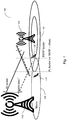
- FIGS 1 and 2 are schematic illustrations of an example communication network or system 100 that includes a small cell 102 with a low power access node 104 (e.g. a low power node) serving a user equipment (UE) 106.
- the communication network 100 also includes a macro cell 108 with an access node 110 (e.g. a base station) serving another UE 112.
- a small cell 102 with a low power access node 104 (e.g. a low power node) serving a user equipment (UE) 106.
- the communication network 100 also includes a macro cell 108 with an access node 110 (e.g. a base station) serving another UE 112.
- an access node 110 e.g. a base station
- Figure 1 illustrates the macro cell 108 and small cell 102 defining a path loss (PL) border and a Reference Signal Received Power (RSRP) border.
- the RSRP border for the small cell 102 is located where a UE 106 in the small cell 102 experiences the same received power for downlink signals from the access node 110 of the macro cell 108 and downlink signals from the access node 104 of the small cell 102.
- the PL border for the small cell 102 is located where the UE experiences the same path loss for the downlink signals of the macro cell 108 and small cell 102.
- the RSRP border results in a smaller coverage area for the small cell 102. This cross over may determine the small cell 102 uptake area, i.e. the area when macro cell UEs 112 move into the coverage of the small cell 102, and vice-versa for small cell UEs 106.
- a macro user using UE 112 close to or on the cell edge of the small cell 102 may cause interference with UE 106 in the small cell 102.
- the UE 112 has a lower path loss to the small cell 102, which means the UE 112 of the macro user can cause a lot of interference to the small cell 102 and also to each UE 106 within the small cell 102.
- SINR UE 1 P 1 G 11 /( P 2 G 21 + N 0 ), where P 1 is the uplink transmit power of UE 106 of the small cell 102, G 11 is the uplink path loss from UE 106 of the small cell 102 to the access node 104 of the small cell 102, P 2 is the uplink transmit power of UE 112 of the macro cell 108, G 21 is the uplink path loss from UE 112 of the macro cell 108 to the access node 104 of the small cell 102, and N 0 is the noise such as additive white Gaussian noise experienced by UE 106.
- a macro cell UE 112 on the edge of the macro cell 108 will experience a lower uplink path loss, G 21 , to the access node 104 of the small cell 102 compared with the uplink path loss, G 22 , to the access node 110 of the macro cell 108.
- This means that the macro cell UE 112 will cause a lot of interference to the small cell UE 106.
- One way to combat the increase in uplink interference is to increase the received/transmitted signal strength, e.g. received/transmitted signal strength target ( P 0) or the uplink power control target, on the uplink used by each UE 106 in the small cell 102 by a power offset (P offset ).
- P 0 is used to represent the received signal strength target for the uplink signal associated with UE 106 received by node 104 of small cell 102. It is to be appreciated, that P 0 could alternatively be an transmit signal strength target for the uplink signal associated with UE 106 transmitted by UE 106 to node 104 of small cell 102.
- FIG. 3 is an illustration of four scenarios 301, 302, 303 and 304 showing how the performance for a UE 106 in the small cell 102 (e.g. a pico cell) changes with different uplink power control settings in relation to a received signal strength target ( P 0) at the access node 104 of the small cell 102.
- Each scenario represents a graph of the user throughput (e.g. User Thput) in Megabits per second (Mbps) vs time in seconds.
- the throughput performance of the small cell UE 106 e.g. pico cell user
- the throughput performance of the macro cell UE 112 e.g. macro cell user
- the small cell UE 104 transmits for 5 seconds, after which the macro cell UE 112 beings to transmit and both the small cell UE 104 and macro cell UE 112 transmit for a further 18 seconds.
- the received signal strength power target ( P 0) for the small cell UE 104 and the macro cell UE 112 that is received at the access node 104 of the small cell 102 are set at -103dBm.
- the small cell UE 106 has excellent throughput performance of around 40Mbps, however, once the macro cell UE 112 begins transmitting the throughput performance of the small cell UE 106 drops significantly to around 1Mbps, while the macro cell UE 112 enjoys a throughput performance of around 35-38Mbps.
- the received signal strength power target ( P 0) for the small cell UE 104 is set to -100dBm and that of the macro cell UE 112 is set to -103.
- the small cell UE 106 has excellent throughput performance of around 40Mbps, however, once the macro cell UE 112 begins transmitting the throughput performance of the small cell UE 106 still drops significantly to around 2-3Mbps, while this is an improvement, it is evident that the macro cell UE 112 degrades further to around 31-33Mbps.
- the received signal strength power target ( P 0) for the small cell UE 104 is set to -97dBm and that of the macro cell UE 112 is set to -103.
- the small cell UE 106 has excellent throughput performance of around 40Mbps, however, once the macro cell UE 112 begins transmitting the throughput performance of the small cell UE 106 still drops significantly to around 5Mbps, while this is an improvement, it is evident that the macro cell UE 112 degrades further to around 30Mbps.
- the received signal strength power target ( P 0) for the small cell UE 104 is set to -87dBm and that of the macro cell UE 112 is set to -103.
- the small cell UE 106 has excellent throughput performance of around 40Mbps, however, once the macro cell UE 112 begins transmitting the throughput performance of the small cell UE 106 still drops to around 15-17Mbps, while this is an improvement, it is evident that the macro cell UE 112 significantly degrades further to around 11-12Mbps.
- US2012/028673A1 relates to a method for controlling uplink power by a mobile station in a wireless communication system and a system including an upper layer base station and a lower layer base station.
- WO2010/121635A1 relates to methods and apparatuses for providing power control in a mobile network wherein a base station calculates power control values for one or more terminals in the network.
- US2012/142334A1 relates to a radio communication system in which a radio terminal controls the transmission power of a radio signal to a base station based on a propagation loss between the terminal and base station.
- WO2011/055555A1 relates to a control unit in a network calculating a path loss and an offset and taking the power offset into consideration when calculating a target power.
- 3GPP Technical Specification Group Radio Access Network
- E-UTRA Evolved Universal Terrestrial Radio Access
- HeNB FDD Home eNode B
- RF Radio Frequency
- the invention is set out in the appended set of claims. It is an object of the present invention to provide methods and apparatus of providing an uplink power control scheme that can be used in a communication system, e.g. such as a Heterogeneous Network (HetNet) deployment, to control the uplink interference in both macro cells and small low power cells. It is proposed herein that the uplink power control scheme in the small cells uses an SINR based uplink power control that is controlled by the difference in downlink output power between a macro cell and a small low power cell.
- HetNet Heterogeneous Network
- a method for uplink power control in a communication network or system including a low power cell with a low power node serving a UE and a macro cell with a base station serving one or more other UE(s).
- the low power cell is a neighbour of the macro cell.
- the method, performed by the low power node includes determining a power offset between the macro cell and the low power cell and calculating a received power spectral density target for the UE based on the minimum of: a) a first signal strength target for the UE and an estimated noise and interference power; or b) a second signal strength target for the UE and the calculated power offset.
- the method further includes adjusting the uplink power control for the UE based on the received power spectral density target.
- the first signal strength target may be based on a signal-to-interference plus noise ratio (SINR) target for the UE.
- the method further includes determining the SINR target for the UE based on the noise and interference power to achieve a sufficient throughput performance for the UE while minimizing any impact on throughput performance for the one or more other UE(s) in the macro cell.
- the second signal strength target may be based on the signal strength derived from a signal strength target for the UE.
- the first and second signal strength targets are initially the same.
- the step of adjusting the uplink power control for the UE further includes determining an uplink power control adjustment based on the received power spectral density and transmitting the uplink power control adjustment to the UE.
- adjusting the uplink power control for the UE further includes performing closed loop uplink power control for the UE based on the received power spectral density.
- adjusting the uplink power control for the UE further includes performing uplink power control based on the uplink scheduling grant on a Physical Downlink Control Channel (PDCCH).
- PDCH Physical Downlink Control Channel
- adjusting the uplink power control for the UE further comprises determining an uplink power control target for the UE based on the received power spectral density target, and transmitting the uplink power control target to the UE for reconfiguring the transmit power of the UE.
- the uplink power control target for the UE may be transmitted to the UE using Radio Resource Control (RRC) signalling.
- RRC Radio Resource Control
- the method may include estimating the estimated noise and interference power by estimating an interference power corresponding to one or more of the other UE(s) in the macro cell.
- determining a power offset further includes calculating the power offset based on the downlink power difference between the macro cell and the low power cell.
- determining the power offset further includes receiving at the low power node a downlink transmit power level associated with the macro cell from the base station.
- determining the power offset may further include calculating the downlink transmit power difference based on the received macro cell downlink transmit power and the low power node downlink transmit power.
- determining the power offset further includes calculating the power offset based on a cell offset parameter.
- the low power cell overlaps with the macro cell.
- the communication system may further include one or more further macro cell(s) with one or more further base station(s), each further base station serving one or more further UE(s), and the lower power cell is a neighbour of each of the further macro cell(s), where calculating the power offset further includes taking into account the further macro cell(s).
- calculating the power offset further includes taking into account the downlink power difference between the neighbouring macro cell(s) and the low power cell.
- calculating the power offset further includes calculating the power offset after receiving the downlink output power levels from the neighbouring macro cells.
- calculating the power offset may be based on at least any one or more of the following: the average downlink output power levels received from the neighbouring macro cells; the maximum downlink output power level received from the neighbouring macro cells; the minimum downlink output power level received from the neighbouring macro cells; and/or the downlink output power level received from the neighbouring macro cell that is closest to the UE.
- estimating the interference power further includes estimating an interference power based on the further UE(s).
- an apparatus for uplink power control in a communication system including a low power cell with a low power node serving a UE and a macro cell with a base station serving one or more other UE(s), where the low power cell is a neighbour of the macro cell.
- the apparatus includes a processor, a receiver, a transmitter, and a memory, the processor connected to the receiver, the transmitter and the memory.
- the processor is configured to determine a power offset between the macro cell (108) and the low power cell (102), calculate a power spectral density target for the UE (106) based on the minimum of: a) a first signal strength target for the UE (106), an estimated noise power, and the estimated interference; or b) a second signal strength target for the UE (106) and the calculated power offset; and adjust the uplink power control for the UE (106) based on the received power spectral density target.
- the first signal strength target for the UE is based on a SINR target for the UE.
- the processor is further configured to determine the SINR target for the UE based on the noise and interference power to achieve a sufficient throughput performance for the UE while minimizing any impact on throughput performance for the one or more other UE(s) in the macro cell.
- the second signal strength target is based on a signal strength derived from a SNR target for the UE.
- the first and second signal strength targets are initially the same.
- the processor is further configured to adjust the uplink power control for the UE by determining an uplink power control adjustment based on the received power spectral density.
- the transmitter may be configured to transmit the uplink power control adjustment to the UE.
- the processor, receiver, and transmitter are further configured to adjust the uplink power control for the UE by performing closed loop uplink power control for the UE based on the received power spectral density.
- the processor and transmitter may be configured to adjust the uplink power control based on the uplink scheduling grant on a PDCCH.
- the processor may be further configured to adjust the uplink power control for the UE by determining a power control target for the UE based on the received power spectral density target.
- the transmitter may be further configured to transmit the power control target to the UE for reconfiguring the transmit power of the UE.
- the transmitter may be configured to transmit the uplink power control target for the UE using RRC signalling.
- the processor is configured to estimate the interference power corresponding to one or more of the other UE(s) in the macro cell.
- the processor may be configured to determine the power offset by calculating the power offset based on the downlink power difference between the macro cell and the low power cell.
- the receiver may be configured to receive a downlink transmit power level associated with the macro cell from the base station, and the processor may be configured to determine the power offset by calculating the downlink transmit power difference based on the received macro cell downlink transmit power and the low power node downlink transmit power.
- the processor may be configured to determine the power offset by further calculating the power offset based on a cell offset parameter.
- the low power cell overlaps with the macro cell.
- the communication system further includes one or more further macro cell(s) with one or more further base station(s), each further base station serving one or more further UE(s).
- the lower power cell is a neighbour of each of the further macro cell(s), where the processor is further configured to calculate the power offset taking into account the further macro cell(s).
- the processor is further configured to calculate the power offset by taking into account the downlink power difference between the neighbouring macro cell(s) and the low power cell. Additionally the processor may be further configured to calculate the power offset after receiving the downlink output power levels from the neighbouring macro cells.
- the processor may be further configured to calculate the power offset based on either or at least one or more of: the average downlink output power levels received from the neighbouring macro cells; the maximum downlink output power level received from the neighbouring macro cells; the minimum downlink output power level received from the neighbouring macro cells; and/or the downlink output power level received from the neighbouring macro cell that is closest to the UE.
- the processor may be further configured to estimate the interference power based on the further UE(s).
- the apparatus is implemented in the low power node.
- FIG. 1 may depict a computer program, comprising computer readable code means which, when run from a computer readable medium in the form of a memory in a processor of an apparatus, causes the apparatus to perform the method(s) as described.
- a computer program product may also be provided comprising said computer readable medium and said computer program, where the computer program is stored on the computer readable medium.
- the invention provides the advantage of an uplink power control scheme capable of coordinating the used uplink power within neighbouring macro and small low power cells.
- a further advantage is that the uplink power control scheme removes the need for manual tuning of the uplink power control settings for UEs in the small low power cells.
- another advantage is the ability to control the uplink interference level in the communication system further increasing total uplink system capacity and/or throughput.
- Another advantage is the reduction in battery consumption for UEs in small low power cells as the macro and small low power cells are able to coexist.
- an communications network e.g. an IP communications network
- an uplink power control scheme in the small low power cells (e.g. pico or micro cells) that uses an SINR based closed loop for uplink power control.
- the SINR based close loop is also controlled by the difference in downlink output power between the macro cell and the small cell.
- the SINR based closed loop lets the UE, in the small cell, to increase the output power when it is under strong interference from macro users and at the same time it is controlled so that UEs in the small cell do not cause too high interference levels to surrounding macro cells.
- Figure 4a is a diagram illustrating an example process for an uplink power control scheme for UE(s) in a low power cell.
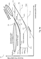
- Figure 4 illustrates a graph of received power spectral density (PSD) vs Interference (dBm/PRB) for a UE in a small low power cell.
- the received signal strength target, denoted P 0, for the uplink signal received from the UE at the node of the low power cell is represented by dashed line 401
- the noise level e.g. AWGN
- the received signal strengh target P 0 401 can be set by the node of the small low power cell to ensure the UE maintains a certain throughput, data rate, and/or quality of service, etc.
- the interference level (e.g. from UEs in a neighbouring macro cell or other communication/electronic/industrial interference) is represented by dashed line 403.
- the noise plus interference level is represented by the solid line 404.
- the noise level 402 and interference level 403 are represented as being linear, however, it is to be appreciated that the noise level 402 and/or interference level 403 may vary or may be represented as a non-linear function or non-linear lines.
- the UE is provided with an SNR target 405a above the noise level 402 to meet the received signal strength target P 0 401 when there is no interference level 403.
- the received PSD target is represented by the solid line 406, 406a and 406b.
- the received PSD target 406a is the same as the received signal strength target P 0 401.
- the noise-plus-interference level 404 is increased.
- the received PSD target takes into account the interference-plus noise and increases to allow the UE to maintain its level of service.
- the SNR target 405a now becomes an SINR target 405b that is set to be above the noise-plus-interference level.
- the interference level 403 may continue to increase, e.g. as more and more UEs use the macro cell and/or more UEs use the small cell, and in order for the UE to maintain the same SINR target above the noise-plus-interference level 405, this means the received PSD target 406 also increases.
- the received PSD target 406 is and the UE's transmission power are allowed to increase unchecked to to maintain the UE's level of service, then the UE will generate excessive interference to the UEs in the macro cell and/or other UEs in the small cell (e.g.
- the increase in output power for the UE's in the small cell could be even larger compared to the fixed P 0 adjustment.
- using only SINR based power control may solve the problem of excess interference when the interference level 403 is low but can instead cause excessive interference, to e.g. a macro cell, when the interference is high as illustrated by the received PSD target 406b. This can also lead to an increased drain of batteries in the UEs as they try and combat increasing interference level 403 with an increasing level of transmit power in the uplink.
- the uplink power control scheme described herein solves this problem of excessive interference when the received noise-plus-interference level 404 is high by introducing an upper limit for the received PSD target 406.
- the upper limit for the received PSD target 406 is illustrated by the solid line 407, 407a and 407b.
- this line 407 and 407a is similar to or identical to the SINR based power control or received PSD target 406 and 406a, but when the noise-plus-interference level 404 reaches a certain level the SINR based power control will require a received PSD target 407 that is considered to generate too much interference to neighbor (e.g. macro) cells.
- the uplink power control scheme limits the received PSD target 407 to P 0 + P offset in order to maintain a reasonable SINR in neighbor (macro) cells.
- the P 0 + P offset level is illustrated as the dotted line 408.
- the first signal strength target ( SINR target ) for a UE may be set to an SNR target called the signal-to-noise ratio target.
- P 0 is a second signal strength target (e.g. a power control target) sent to the UE (e.g. through RRC signaling or other side channel signaling), and P offset is a power offset for the low power cell used to limit the PSD rx,target .
- P 0 may be set so that the SINR target is reached at the cell edge in a low load scenario.
- the conventional 3GPP closed loop power control may be used. For example, this may be performed by transmitting a UE specific power adjustment included in the uplink scheduling grant on PDCCH and is updated fast enough to follow slow fading. Alternatively, changes to P 0 may be signaled to the UE, which may require RRC signaling.
- P dlPowerDifference the difference in downlink transmit/output power
- the downlink transmit/output powers may be received by the small cell over the X2 interface.
- the macro cell(s) having a neighbor relation to the small cell may be configured to send their downlink output power level to the small cell. This could be performed the first time the relation between the macro cells and small cell is determined and registered or added or at a change of downlink output power levels within the macro cell(s).
- the power control compensation factor ( P offset ) is then set by the difference in downlink output power ( P dlPowerDifference ) between the macro cell and the small cell.
- P dlPowerDifference the difference in downlink output power
- Other parameters or offsets may also be taken into account when calculating P offset .
- CO cell offset
- CSO cell selection offset
- P offset P dlPowerDifference - CSO [ dB ]
- P offset P dlPowerDifference - CO [ dB ].
- Other parameters that are used to extend or adjust the coverage of the small cell may also be used in calculating P offset .
- each UE will increase their output power when there are one or more UEs of macro users that are causing large uplink interference towards the small cell 102.
- the benefit with this solution when compared to fixed adjustment of the uplink power control target using only SINR closed loop power control, which can lead to excessive interference to the macro cell, is that the UEs in the small cell will only use higher output power when needed. This will create less interference towards neighbor cells and save battery in the UE when there is no heavy uplink interference from macro users.
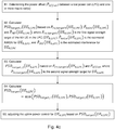
- FIG. 4b is a flow diagram illustrating another example process for uplink power control in a communication system 100.
- the communication system 100 includes a low power cell 102 with a low power node 104 serving at least one UE 106.
- the communication system 100 also includes a macro cell 108 with a base station 110 serving one or more other UE(s) 112.
- the low power cell 102 is a neighbour of the macro cell 108.
- the uplink power control scheme, performed by the low power node 104 may include the following steps:
- FIG. 4c is another flow diagram illustrating an example process for uplink power control in the communication system 100.
- the communication system 100 includes a low power cell 102 with a low power node 104, where the low power node 104 serves 0 ⁇ k ⁇ K UEs.
- the communication system 100 also includes one or more macro cell(s) 108 with a base station 110 serving one or more other UE(s) 112.
- the low power cell 102 is a neighbour of at least one of the macro cell(s) 108.
- the uplink power control scheme, performed by the low power node 104 for the k th UE 106 of the low power cell 102 denoted UE k,LPC may include the following steps:
- the first signal strength target, P rx,target 1 may be based on an SINR target for UE k , LPC 106 denoted P SINR , target ( UE k , LPC ).
- the process may also include a step for determining the SINR target for UE k , LPC 106 based on the noise and interference power (e.g.
- P ⁇ noise ( UE k , LPC ) and P ⁇ INT ( UE k , LPC )) to achieve a sufficient throughput performance for UE k , LPC 106 while minimizing any impact on throughput performance for the one or more other UE(s) 112 in the macro cell that neighbours the low power cell 102.
- P rx , target 1 ( UE k , LPC ) may be set as an SNR target for UE k , LPC 106.
- the second signal strength target, P rx,target 2 may be based on the signal strength derived from a signal strength target for the UE 106.
- P rx , target 2 ( UE k , LPC ) may be the received signal strength target (P0) for UE k , LPC 106 denoted P 0( UE k , LPC ).
- P rx , target 2 ( UE k , LPC ) P 0( UE k , LPC )
- PSD target ,2 ( UE k,LPC ) P rx , target 2 ( UE k , LPC ) + P offset .
- the first and second signal strength targets may initially be set to be the same e.g. when P ⁇ INT ( UE k , LPC ) is negligable, and then these targets may be based on an SNR target.
- adjusting the uplink power control for UE k , LPC 106 may further include the steps of determining an uplink power control adjustment based on PSD target ( UE k , LPC ) and transmitting the uplink power control adjustment to for UE k , LPC 106.
- adjusting the uplink power control for UE k , LPC 106 may further include performing closed loop uplink power control for UE k , LPC 106 based on the PSD target ( UE k , LPC ).
- the closed loop uplink power control may be an SINR based closed loop uplink power control.
- adjusting the uplink power control for UE k , LPC 106 may further include performing uplink power control based on the uplink scheduling grant on a PDCCH or similar control channel used for uplink power control.
- adjusting the uplink power control for UE k , LPC 106 may further include determining an uplink power control target for UE k , LPC 106 based on the PSD target ( UE k , LPC ), and transmitting the uplink power control target to UE k , LPC 106 for reconfiguring the transmit power of UE k , LPC 106.
- the uplink power control target for the UE (106) is transmitted to the UE (106) using Radio Resource Control, RRC, signalling or other similar signalling or signalling channel.
- the process may further include the step of estimating P ⁇ INT ( UE k , LPC ) based on one or more of the other UE(s) 112 in the macro cell 108 that may be interfering with UE k , LPC 106.
- Estimating P ⁇ INT ( UE k , LPC ) may further include estimating interference from other sources, e.g. other communication networks, that may be interfering with UE k , LPC 106.
- determining the power offset, ( P offset ), between the low power cell 102 and the macro cell 108 may further include calculating the P offset based on the downlink power difference between the macro cell and the low power cell. For example, determining the P offset may further include receiving at the low power node 102 a downlink transmit power level associated with the macro cell 108 from the base station 110. The downlink transmit power difference may be calculated based on the received macro cell downlink transmit power and the low power node downlink transmit power. Additionally, other parameters may be taken into account when calculating the P offset , for example, determining the P offset may further include calculating P offset based on a cell offset or cell selection offset, or other parameter used for calculating P offset .
- FIG 5a is a schematic illustration of the communication system 100 including a plurality of macro cells 108a-108c and a low power cell 102a and figure 5b is another flow diagram illustrating another example process for uplink power control in the communication system 100.
- the communication system 100 includes a low power cell 102a with a low power node 104, where the low power node 104 serves 0 ⁇ k ⁇ K UEs, in this case, there are two UEs, a k th UE 106a that is denoted UE k , LPC and another UE 106b.
- the communication system 100 also includes a plurality of macro cell(s) 108a-108c, in which each of the macro cells 108a-108c includes a base station 110a-110c serving one or more corresponding other UE(s) 112a-112c.
- the low power cell 102a is a neighbour of macro cell(s) 108a-108c.
- the coverage of the low power cell 102a may be extended such that the low power cell 102a overlaps with one or more of the macro cells 108a-108c as represented by the dashed line of low power cell 102b.
- the node 104 of low power cell 102a may use a cell selection offset, cell offset parameter or other type of parameter for extending coverage of the low power cell 102a to that of low power cell 102b.
- the process defining the uplink power control scheme may be performed by the low power node 104 for each UE 106a-106b in the low power cell 102a.
- the process performed by the low power node 104 for the k th UE 106a of the low power cell 102a may include the following steps:
- determining and/or calculating the P offset may include taking into account the further macro cell(s) 108a-108c. This may be performed by taking into account the downlink power difference between the neighbouring macro cell(s) 108a-108c and the low power cell 102.
- determining the power offset, ( P offset ), between the low power cell 102 and the macro cells 108a-108c may further include calculating the P offset based on the downlink power difference between each macro cell 108a-108c and the low power cell 102.
- determining the P offset may further include receiving at the low power node 102 a downlink transmit power level associated with each macro cell 108a-108c from the corresponding base stations 110a-110c.
- the downlink transmit power difference may be calculated based on the received macro cell downlink transmit powers and the low power node downlink transmit power.
- other parameters may be taken into account when calculating the P offset , for example, determining the P offset may further include calculating P offset based on a cell offset or cell selection offset, or other parameter used for calculating P offset .
- calculating the P offset may be based on either or at least one of: the average downlink output power levels received from the neighbouring macro cells 108a-108c; the maximum downlink output power level received from the neighbouring macro cells 108a-108c; the minimum downlink output power level received from the neighbouring macro cells 108a-108c; and/or the downlink output power level received from the neighbouring macro cell 108a-108c that is closest to UE k , LPC 106a.
- the P offset may be calculated after receiving the downlink output power levels from each of the neighbouring macro cells 108a-108c.
- the process may further include the step of estimating P ⁇ INT ( UE k , LPC ) based on one or more of the other UE(s) 112a-112c in the macro cells 108a-108c that may be interfering with UE k , LPC 106a.
- Estimating P ⁇ INT ( UE k , LPC ) may further include estimating interference from other sources, e.g. other communication networks, industrial sources, other devices in the vicinity of UE k , LPC 106a, that may be interfering with UE k , LPC 106a.
- P ⁇ noise ( P k , LPC ) and P ⁇ INT ( UE k , LPC )) to achieve a sufficient throughput performance for UE k , LPC 106a while minimizing any impact on throughput performance for the one or more other UE(s) 112 in the macro cell that neighbours the low power cell 102.
- P rx , target 1 ( UE k , LPC ) may be set as an SNR target for UE k , LPC 106a.
- the second signal strength target, P rx , target 2 may be based on the signal strength derived from a signal strength target for the UE 106a.
- P rx,target 2 ( UE k , LPC ) may be the received signal strength target (P0) for UE k , LPC 106a denoted P 0( UE k , LPC ).
- the first and second signal strength targets may initially be set to be the same e.g. when P ⁇ INT ( UE k , LPC ) is negligable, and then these targets may be based on an SNR target.
- adjusting the uplink power control for UE k , LPC 106a may further include the steps of determining an uplink power control adjustment based on PSD target ( UE k , LPC ) and transmitting the uplink power control adjustment to for UE k , LPC 106a.
- adjusting the uplink power control for UE k , LPC 106a may further include performing closed loop uplink power control for UE k , LPC 106a based on the PSD target ( UE k , LPC ) .
- the closed loop uplink power control may be an SINR bsaed closed loop uplink power control.
- adjusting the uplink power control for UE k , LPC 106a may further include performing uplink power control based on the uplink scheduling grant on a PDCCH or similar control channel used for uplink power control.
- adjusting the uplink power control for UE k , LPC 106a may further include determining an uplink power control target for UE k , LPC 106a based on the PSD target ( UE k , LPC ), and transmitting the uplink power control target to UE k , LPC 106a for reconfiguring the transmit power of UE k , LPC 106.
- the uplink power control target for UE k , LPC 106a is transmitted to UE k , LPC 106a using RRC signalling or other similar signalling or signalling channel.
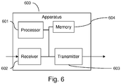
- FIG. 6 is a schematic illustration of an apparatus 600 for use in uplink power control in a communications network 100 (e.g. a HetNet).
- the communication system 100 may include a low power cell 102 with a low power node 104 serving a UE 106 and a macro cell 108 with a base station 110 serving one or more other UE(s) 112.
- the low power cell 102 is a neighbour of the macro cell 108 and low power cell 102 may overlap with the macro cell 108.
- the apparatus 600 includes a processor 601, receiver 602, transmitter 603, memory 604, and the processor 601 being coupled to the receiver 602, the transmitter 603, and the memory 604.
- the memory 604 may be a computer readable medium that may include computer program or instructions stored thereon, which when executed, may configure the processor 601, receiver 602, and transmitter 603 to implement the processes for performing uplink power control as described herein.
- the processor 601 may be is configured to determine a power offset between the macro cell 108 and the low power cell 102.
- the processor 601 may then be configured to calculate a power spectral density target for the UE 106 based on the minimum of: a) a first signal strength target for the UE 106, an estimated noise power, and the estimated interference; or b) a second signal strength target for the UE 106 and the calculated power offset.
- the processor 601 and the transmitter 603 may be further configured to adjust the uplink power control for the UE 106 based on the received power spectral density target.
- the first signal strength target for the UE 106 may be based on a SINR target for the UE 106.
- the processor may also be further configured to determine the SINR target for the UE 106 based on the noise and interference power to achieve a sufficient throughput performance for the UE 106 while minimizing any impact on throughput performance for the one or more other UE(s) 112 in the macro cell 108.
- the second signal strength target may be based on a signal strength derived from a received signal strength target for the UE 106. For example, a SNR target for the UE 106 when there is no interference or low interference condition exists in the low power cell 102.
- the processor may also be further configured to determine the received signal strength target for the UE 106 based on the noise and to achieve a sufficient throughput performance for the UE 106 in a low interference scenario. Initially, the first and second signal strength targets may be initially set to be the same.
- the processor 601 may be further configured to adjust the uplink power control for the UE 106 by determining an uplink power control adjustment based on the received power spectral density.
- the transmitter 603 is configured to transmit the uplink power control adjustment to the UE 106.
- the processor 601, receiver 602, and transmitter 603 may be further configured to adjust the uplink power control for the UE 106 by performing closed loop uplink power control for the UE 106 based on the calculated received power spectral density.
- the processor 601 and transmitter 603 may be configured to adjust the uplink power control based on the uplink scheduling grant on a PDCCH or any other similar control channel.
- the processor 601 may be further configured to adjust the uplink power control for the UE 106 by determining a power control target (or uplink power control target) for the UE (106) based on the received power spectral density target.
- the transmitter 603 is further configured to transmit the power control target to the UE 106 for reconfiguring the transmit power of the UE 106.
- the transmitter 603 may be configured to transmit the uplink power control target for the UE 106 using RRC signalling.
- the processor 601 and/or the receiver 602 may be configured to estimate the interference power corresponding to one or more of the other UE(s) 112 in the macro cell 108. Additionally or alternatively, the processor 601 and/or the receiver 602 may be further configured to estimate the interference power based on other interference sources such as other communication networks, industrial interference sources, or interference from other devices in the vicinity of UE 106.
- the processor 601 may be configured to determine the power offset by calculating the power offset based on the downlink power difference between the macro cell 108 and the low power cell 102.
- the receiver 602 may be configured to receive a downlink transmit power level associated with the macro cell 108 from the base station 110.
- the processor 601 may be configured to determine the power offset by calculating the downlink transmit power difference based on the received macro cell downlink transmit power and the low power node downlink transmit power. Additionally, the processor 601 may be configured to determine the power offset by further calculating the power offset based on a cell offset or cell selection offset or any other parameter or offset parameter.
- the processor 601 may be further configured to calculate the power offset taking into account the further macro cell(s) 108a-108c.
- the processor 601 may be further configured to calculate the power offset by taking into account the downlink power difference between the neighbouring macro cell(s) 108a-108c and the low power cell 102.
- the processor may be configured to calculate the power offset after receiving the downlink output power levels from the neighbouring macro cells 108a-108c.
- the processor 601 may be further configured to calculate the power offset based on either, or at least one or more of: the average downlink output power levels received from the neighbouring macro cells 108a-108c; the maximum downlink output power level received from the neighbouring macro cells 108a-108c; the minimum downlink output power level received from the neighbouring macro cells 108a-108c; and/or the downlink output power level received from the neighbouring macro cell 108a-108c that is closest to the UE 106a.
- the processor 601 is further configured to estimate the interference power based on the further UE(s) 112a-112c.
- the apparatus 600 may be implemented in the low power node 104 of the low power cell 102 for use in performing uplink power control in relation to the UE 106, 106a-106b being served by the low power node 104.
- the base stations, nodes, low power nodes, UEs, network entities, apparatus and computing systems as described herein each may perform the methods and processes as described herein.
- the processors of such systems are configured to execute computer program instructions based on the methods and processes described herein, such instructions being contained in a computer-readable medium or non-transitory computer readable medium, such as a memory.
- the computer program instructions may be read into memory from another computer-readable medium or from another device via a communication interface.
- the instructions contained in memory cause the processor of a base stations, nodes, low power nodes, UEs, network entities, or other such apparatus to perform the processes or methods as described herein.
- hardwired circuitry may be used in place of or in combination with the computer program instructions to implement processes and methods consistent with the present invention.
- hardware circuitry may include, but are not limited to, semiconductor chips, integrated circuits, field programmable gate arrays, application-specific integrated circuits, electronically programmable integrated circuits and the like.
- the present invention is not limited to any specific combination of hardware circuitry and/or software.
- a computer program comprising computer readable code means which, when run from a computer readable medium in the form of a memory 604 on a processor 601 of an apparatus 600, causes the apparatus to perform the methods or processes as described herein with reference to figures 1-6 .
- a computer program product comprising a computer readable medium 604 and the computer program, wherein the computer program is stored on the computer readable medium 604.
Landscapes
- Engineering & Computer Science (AREA)
- Computer Networks & Wireless Communication (AREA)
- Signal Processing (AREA)
- Quality & Reliability (AREA)
- Mobile Radio Communication Systems (AREA)
Claims (15)
- Verfahren zur Uplink-Leistungssteuerung in einem Kommunikationssystem (100), das eine leistungsarme Zelle (102) mit einem leistungsarmen Knoten (104), die ein Anwenderendgerät, AE, (106) bedienen, und eine Makrozelle (108) mit einer Basisstation (110) umfasst, die ein oder mehrere andere AEs (112) bedienen, wobei die leistungsarme Zelle (102) ein Nachbar der Makrozelle (108) ist, wobei das Verfahren, das vom leistungsarmen Knoten (104) durchgeführt wird, einschließt:Bestimmen (A1; B1) eines Leistungsversatzes zwischen der Makrozelle (108) und der leistungsarmen Zelle (102) basierend auf einer Downlink-Leistungsdifferenz zwischen der Makrozelle (108) und der leistungsarmen Zelle (102);Schätzen einer geschätzten Rausch- und Interferenzleistung durch Schätzen einer Interferenzleistung, die einem oder mehreren des einen oder mehrerer anderer AEs in der Makrozelle entspricht;Bestimmen (A2-A4; B2-B5) eines Empfangsleistungs-Spektraldichteziels für das AE (106) so, dass es das kleinere von zwei berechneten Leistungs-Spektraldichtezielen ist:a) einem Leistungs-Spektraldichteziel (406), das auf einem ersten Signalstärkeziel für Übertragung durch das AE (106) und der geschätzten Rausch- und Interferenzleistung basiert; undb) einem Leistungs-Spektraldichteziel (408), das auf einem zweiten Signalstärkeziel für Übertragung durch das AE (106) und dem berechneten Leistungsversatz basiert; undAnpassen (A5; B6) der Uplink-Leistungssteuerung für das AE (106) basierend auf dem Empfangsleistungs-Spektraldichteziel.
- Verfahren nach Anspruch 1, wobei das erste Signalstärkeziel auf einem Signal-zu-Interferenz-plus-Rauschverhältnis-, SINR, Ziel für das AE (106) basiert, und gegebenenfalls weiter das Bestimmen des SINR-Ziels für das AE (106) basierend auf der Rausch- und Interferenzleistung umfassend, wobei das SINR-Ziel für das AE (106) oberhalb der Rausch-plus-Interferenzleistung eingestellt wird, um eine ausreichende Durchsatz-Performance für das AE (106) zu erzielen, während das SINR-Ziel begrenzt wird, um jede Auswirkung der Übertragungsleistung des AE (106) auf Durchsatz-Performance für das eine oder mehrere andere AEs (112) in der Makrozelle zu minimieren.
- Verfahren nach einem vorstehenden Anspruch, wobei das zweite Signalstärkeziel auf der aus einem Signal-zu-Rauschverhältnis-Ziel für das AE (106) abgeleiteten Signalstärke basiert, und/oder wobei das erste und zweite Signalstärkeziel ursprünglich dieselben sind.
- Verfahren nach einem vorstehenden Anspruch, wobei das Anpassen der Uplink-Leistungssteuerung für das AE (106) weiter das Bestimmen einer Uplink-Leistungssteuerungsanpassung basierend auf der Empfangsleistungs-Spektraldichte, und Übertragen der Uplink-Leistungssteuerungsanpassung an das AE (106) umfasst, und/oder wobei das Anpassen der Uplink-Leistungssteuerung für das AE (106) weiter das Durchführen von Uplink-Leistungssteuerung für das AE (106) in einer geschlossenen Schleife basierend auf der Empfangsleistungs-Spektraldichte umfasst.
- Verfahren nach einem vorstehenden Anspruch, wobei das Anpassen der Uplink-Leistungssteuerung für das AE (106) weiter das Durchführen von Uplink-Leistungssteuerung basierend auf der Uplink-Planungsgewährung auf einem physikalischen Downlink-Steuerkanal, PDCCH, umfasst, und/oder wobei das Anpassen der Uplink-Leistungssteuerung für das AE (106) weiter das Bestimmen eines Uplink-Leistungssteuerungsziels für das AE (106) basierend auf dem Empfangsleistungs-Spektraldichteziel, und Übertragen des Uplink-Leistungssteuerungsziels an das AE (106) zum Neukonfigurieren der Übertragungsleistung des AE (106) umfasst, und gegebenenfalls wobei das Uplink-Leistungssteuerungsziel für das AE (106) unter Verwendung von Funkressourcensteuerungs-, RRC, Signalisierung an das AE (106) übertragen wird.
- Verfahren nach einem vorstehenden Anspruch, wobei die geschätzte Rausch- und Interferenzleistung das Schätzen einer Interferenzleistung umfasst, die einem oder mehreren der anderen AEs (112) in der Makrozelle (108) entspricht.
- Verfahren nach einem vorstehenden Anspruch, wobei das Bestimmen des Leistungsversatzes umfasst:Empfangen, am leistungsarmen Knoten (102) von der Basisstation (110), eines Downlink-Übertragungsleistungspegels, der mit der Makrozelle (108) assoziiert ist; undBerechnen der Downlink-Übertragungsleistungsdifferenz in übertragener Leistung basierend auf der empfangenen Downlink-Übertragungsleistung der Makrozelle und der Downlink-Übertragungsleistung des leistungsarmen Knotens.
- Verfahren nach einem vorstehenden Anspruch, wobei das Bestimmen des Leistungsversatzes weiter das Berechnen des Leistungsversatzes basierend auf einem Zellenversatz einschließt, und/oder wobei sich die leistungsarme Zelle (102) mit der Makrozelle (108) überlappt.
- Verfahren nach einem vorstehenden Anspruch, wobei das Kommunikationssystem (100) weiter eine oder mehrere weitere Makrozellen (108a-108c) mit einer oder mehreren weiteren Basisstation(en) (110a-110b) umfasst, wobei jede weitere Basisstation ein oder mehrere weitere AEs (112a-112c) bedient, und die leistungsarme Zelle (102) ein Nachbar von jeder der weiteren Makrozellen (108a-108c) ist, wobei das Berechnen des Leistungsversatzes weiter das Berücksichtigen der weiteren Makrozellen (108a-108c) einschließt, und gegebenenfalls wobei das Berechnen des Leistungsversatzes weiter das Berücksichtigen der Downlink-Leistungsdifferenz zwischen den benachbarten Makrozellen (108a-108c) und der leistungsarmen Zelle (102) einschließt, und gegebenenfalls wobei das Berechnen des Leistungsversatzes weiter das Berechnen des Leistungsversatzes nach Empfangen der Downlink-Ausgangsleistungspegel von den benachbarten Makrozellen (108a-108c) einschließt.
- Verfahren nach Anspruch 9, weiter das Berechnen des Leistungsversatzes umfassend basierend auf entweder:den durchschnittlichen Downlink-Ausgangsleistungspegeln, die von den benachbarten Makrozellen (108a-108c) empfangen werden;dem maximalen Downlink-Ausgangsleistungspegel, der von den benachbarten Makrozellen (108a-108c) empfangen wird;dem minimalen Downlink-Ausgangsleistungspegel, der von den benachbarten Makrozellen (108a-108c) empfangen wurd; oderdem Downlink-Ausgangsleistungspegel, der von der benachbarten Makrozelle (108a-108c) empfangen wied, die am nähesten zum AE (106a) liegt.
- Verfahren nach Anspruch 9 oder 10, weiter das Schätzen der Interferenzleistung umfassend, das weiter das Schätzen einer Interferenzleistung basierend auf den weiteren AEs (112a-112c) einschließt.
- Einrichtung (600) zur Uplink-Leistungssteuerung in einem Kommunikationssystem (100), wobei das Kommunikationssystem (100) eine leistungsarme Zelle (102) mit einem leistungsarmen Knoten (104), die ein Anwenderendgerät, AE, (106) bedienen, und eine Makrozelle (108) mit einer Basisstation (110) umfasst, die ein oder mehrere andere AEs (112) bedienen, wobei die leistungsarme Zelle (102) ein Nachbar der Makrozelle ist, wobei die Einrichtung umfasst:
einen Prozessor (601), einen Empfänger (602), einen Sender (603) und einen Speicher (604), wobei der Prozessor (601) mit dem Empfänger (602), dem Sender (603) und dem Speicher (604) verbunden ist, wobei:
der Prozessor (601) dazu konfiguriert ist:einen Leistungsversatz zwischen der Makrozelle (108) und der leistungsarmen Zelle (102) basierend auf einer Downlink-Leistungsdifferenz zwischen der Makrozelle (108) und der leistungsarmen Zelle (102) zu bestimmen;eine Interferenzleistung durch Schätzen einer Interferenzleistung zu schätzen, die einem oder mehreren des einen oder mehrerer anderer AEs in der Makrozelle entspricht;ein Leistungs-Spektraldichteziel für das AE (106) so zu bestimmen, dass es das kleinere von zwei berechneten Leistungs-Spektraldichtezielen ist:a) einem Leistungs-Spektraldichteziel (406), das auf einem ersten Signalstärkeziel für Übertragung durch das AE (106), einer geschätzten Rauschleistung, und der geschätzten Interferenzleistung basiert; undb) einem Leistungs-Spektraldichteziel (408), das auf einem zweiten Signalstärkeziel für Übertragung durch das AE (106) und dem berechneten Leistungsverssatz basiert; unddie Uplink-Leistungssteuerung für das AE (106) auf dem Empfangsleistungs-Spektraldichteziel basierend anzupassen. - Einrichtung nach Anspruch 12, wobei die Einrichtung im leistungsarmen Knoten implementiert ist.
- Computerprogramm, das computerlesbare Codemittel umfasst, das, wenn es von einem computerlesbaren Medium in der Form eines Speichers (604) in einem Prozessor (601) in einer Einrichtung (600) ausgeführt wird, die Einrichtung dazu bringt, das Verfahren nach einem der Ansprüche 1 bis 11 durchzuführen.
- Computerprogrammprodukt, das ein computerlesbares Medium (604) und ein Computerprogramm nach Anspruch 14 umfasst, wobei das Computerprogramm auf dem computerlesbaren Medium (604) gespeichert ist.
Applications Claiming Priority (1)
| Application Number | Priority Date | Filing Date | Title |
|---|---|---|---|
| PCT/EP2014/059264 WO2015169346A1 (en) | 2014-05-06 | 2014-05-06 | Uplink power control in heterogeneous networks |
Publications (2)
| Publication Number | Publication Date |
|---|---|
| EP3141048A1 EP3141048A1 (de) | 2017-03-15 |
| EP3141048B1 true EP3141048B1 (de) | 2018-08-01 |
Family
ID=50687472
Family Applications (1)
| Application Number | Title | Priority Date | Filing Date |
|---|---|---|---|
| EP14723046.0A Active EP3141048B1 (de) | 2014-05-06 | 2014-05-06 | Uplink-leistungssteuerung in heterogenen netzwerken |
Country Status (3)
| Country | Link |
|---|---|
| US (1) | US10327212B2 (de) |
| EP (1) | EP3141048B1 (de) |
| WO (1) | WO2015169346A1 (de) |
Families Citing this family (7)
| Publication number | Priority date | Publication date | Assignee | Title |
|---|---|---|---|---|
| US11032780B2 (en) * | 2015-09-03 | 2021-06-08 | Qualcomm Incorporated | Power control in wireless networks |
| US10085219B2 (en) * | 2015-11-16 | 2018-09-25 | Telefonaktiebolaget Lm Ericsson (Publ) | Power control in a wireless network |
| RU2741628C1 (ru) * | 2017-08-04 | 2021-01-28 | Гуандун Оппо Мобайл Телекоммьюникейшнз Корп., Лтд. | Способ беспроводной связи и терминальное устройство |
| US12004089B2 (en) * | 2021-03-17 | 2024-06-04 | Hughes Network Systems | Power spectral density limits for regions of a coverage area in a satellite communication system |
| FI130453B (en) | 2021-12-23 | 2023-09-06 | Elisa Oyj | Uplink power control |
| US12432661B2 (en) * | 2022-10-05 | 2025-09-30 | T-Mobile Innovations Llc | Dynamic closed loop power control using a nominal target value |
| CN117915369B (zh) * | 2024-01-19 | 2025-12-05 | 中国联合网络通信集团有限公司 | 一种底噪抑制方法、装置及计算机可读存储介质 |
Family Cites Families (23)
| Publication number | Priority date | Publication date | Assignee | Title |
|---|---|---|---|---|
| US8285216B2 (en) * | 2006-11-01 | 2012-10-09 | Qualcomm Incorporated | Inter-cell power control for interference management |
| JP2010251611A (ja) * | 2009-04-17 | 2010-11-04 | Fujifilm Corp | 太陽電池及びその製造方法 |
| WO2010121635A1 (en) | 2009-04-24 | 2010-10-28 | Nokia Siemens Networks Oy | Power control in femto cells |
| JP5555705B2 (ja) * | 2009-08-11 | 2014-07-23 | 京セラ株式会社 | 小セル基地局及び割り当て制御方法 |
| JP2011101313A (ja) * | 2009-11-09 | 2011-05-19 | Panasonic Corp | 小型基地局装置および送信電力制御方法 |
| CN102845088A (zh) * | 2010-04-16 | 2012-12-26 | 京瓷株式会社 | 无线通信系统、高功率基站、低功率基站及通信控制方法 |
| KR101702666B1 (ko) * | 2010-07-29 | 2017-02-06 | 삼성전자주식회사 | 무선 통신 시스템에서 상향링크 전력 제어 방법 및 장치 |
| US9019791B2 (en) * | 2010-11-03 | 2015-04-28 | Shine C. Chung | Low-pin-count non-volatile memory interface for 3D IC |
| US8526307B2 (en) * | 2011-03-04 | 2013-09-03 | Ntt Docomo, Inc. | Proportional-fair radio resource management |
| EP2719230B1 (de) * | 2011-06-13 | 2023-05-10 | InterDigital Patent Holdings, Inc. | Verfahren zum steuern der sendeleistung einer mobilstation |
| US8849339B2 (en) * | 2011-08-12 | 2014-09-30 | Telefonaktiebolaget L M Ericsson (Publ) | Closed loop power control in a heterogeneous network by selecting among sets of accumulative power step values |
| WO2013025058A2 (ko) * | 2011-08-17 | 2013-02-21 | 엘지전자 주식회사 | 기지국 협력 무선 통신 시스템에서 사운딩 참조 신호를 송신하는 방법 및 이를 위한 장치 |
| CN104067667A (zh) * | 2012-01-23 | 2014-09-24 | 英特尔公司 | 用于集成的多rat异类网络的网络辅助的用户关联和卸载技术 |
| WO2013137545A1 (en) * | 2012-03-13 | 2013-09-19 | Lg Electronics Inc. | Method of controlling transmit power of ue in wireless communication system and apparatus for the same |
| US8849203B2 (en) * | 2012-06-27 | 2014-09-30 | Alcatel Lucent | Discovering proximity devices in broadband networks |
| US9398480B2 (en) * | 2012-11-02 | 2016-07-19 | Telefonaktiebolaget L M Ericsson (Publ) | Methods of obtaining measurements in the presence of strong and/or highly varying interference |
| GB2509948B (en) * | 2013-01-18 | 2015-05-13 | Broadcom Corp | Measurement reporting |
| JP6491433B2 (ja) * | 2013-10-09 | 2019-03-27 | キヤノン株式会社 | 送電装置並びにその制御方法、及びプログラム |
| US9439153B1 (en) * | 2014-04-07 | 2016-09-06 | Sprint Spectrum L.P. | Systems and methods for determining a power option for an access node |
| US9769768B2 (en) * | 2014-04-30 | 2017-09-19 | Alcatel-Lucent Usa Inc. | Method and apparatus for reducing interference in a heterogeneous network |
| WO2015168930A1 (zh) * | 2014-05-09 | 2015-11-12 | 华为技术有限公司 | 控制载波信号的功率的方法、用户设备和基站 |
| US9420606B2 (en) * | 2014-06-25 | 2016-08-16 | Qualcomm Incorporated | Full duplex operation in a wireless communication network |
| US9794157B2 (en) * | 2015-07-30 | 2017-10-17 | Hughes Network Systems, Llc | Optimal open loop power control for random access channel |
-
2014
- 2014-05-06 EP EP14723046.0A patent/EP3141048B1/de active Active
- 2014-05-06 US US15/308,384 patent/US10327212B2/en active Active
- 2014-05-06 WO PCT/EP2014/059264 patent/WO2015169346A1/en not_active Ceased
Also Published As
| Publication number | Publication date |
|---|---|
| EP3141048A1 (de) | 2017-03-15 |
| US10327212B2 (en) | 2019-06-18 |
| US20170055229A1 (en) | 2017-02-23 |
| WO2015169346A1 (en) | 2015-11-12 |
Similar Documents
| Publication | Publication Date | Title |
|---|---|---|
| EP3141048B1 (de) | Uplink-leistungssteuerung in heterogenen netzwerken | |
| EP2974476B1 (de) | System und verfahren zur dynamischen leistungsregelung in kleinen zellen | |
| US8848560B2 (en) | Apparatus and method for adaptive transmission during almost blank subframes in a wireless communication network | |
| EP3399806B1 (de) | System und verfahren zur erleichterung der kleinzelligen uplink-leistungssteuerung in einer netzwerkumgebung | |
| CN102281571B (zh) | 一种功率控制的方法和设备 | |
| US20140200001A1 (en) | Method and apparatus for mobility enhancement | |
| EP2773143B1 (de) | Funkkommunikationssystem, funkbasisstation und kommunikationssteuerungsverfahren zum auswählen eines funkzugangspunkt | |
| US9532314B2 (en) | Method and apparatus for uplink transmission power control of multi-link connections | |
| EP3138324B1 (de) | Auswahl von sender-/empfängerknoten in einem mobiltelekommunikationsnetzwerk | |
| CN102918894B (zh) | 无线网络中用于确定上行链路接收功率目标值的方法和装置 | |
| Chang et al. | A fractional soft handover scheme for 3GPP LTE-advanced system | |
| WO2015011557A1 (en) | Method for determining uplink transmission power | |
| EP2915379B1 (de) | Netzwerkknoten, benutzervorrichtung, verfahren darin, computerprogrammprodukt und computerspeichermedium | |
| EP2823678B1 (de) | Funknetzsteuerung, versorgungsbasisstation, benutzervorrichtung und verfahren darin | |
| US20140206329A1 (en) | Methods, apparatus and computer programs for use in measurement reporting | |
| US10045307B2 (en) | Communication system for setting an uplink target received power for a home base station | |
| US9622185B2 (en) | Wireless communication method, wireless communication system, wireless station, and wireless terminal for adjusting transmission power | |
| US8861412B2 (en) | Interference avoidance in low power nodes | |
| CN104244353A (zh) | 通信方法、无线网络控制器和用户设备 | |
| CN105554862B (zh) | 一种用于异构网中微小区的增强型上行分数功率控制方法 | |
| CN105722148B (zh) | 在lte-a系统的异构网中用于避免无效的负载均衡的方法 | |
| JP5831590B2 (ja) | 通信制御方法、通信システム、および管理サーバ | |
| Wang et al. | On Delay Compensation for HSPA+ HetNet Decoupling |
Legal Events
| Date | Code | Title | Description |
|---|---|---|---|
| STAA | Information on the status of an ep patent application or granted ep patent |
Free format text: STATUS: THE INTERNATIONAL PUBLICATION HAS BEEN MADE |
|
| PUAI | Public reference made under article 153(3) epc to a published international application that has entered the european phase |
Free format text: ORIGINAL CODE: 0009012 |
|
| STAA | Information on the status of an ep patent application or granted ep patent |
Free format text: STATUS: REQUEST FOR EXAMINATION WAS MADE |
|
| 17P | Request for examination filed |
Effective date: 20161104 |
|
| AK | Designated contracting states |
Kind code of ref document: A1 Designated state(s): AL AT BE BG CH CY CZ DE DK EE ES FI FR GB GR HR HU IE IS IT LI LT LU LV MC MK MT NL NO PL PT RO RS SE SI SK SM TR |
|
| AX | Request for extension of the european patent |
Extension state: BA ME |
|
| DAX | Request for extension of the european patent (deleted) | ||
| STAA | Information on the status of an ep patent application or granted ep patent |
Free format text: STATUS: EXAMINATION IS IN PROGRESS |
|
| 17Q | First examination report despatched |
Effective date: 20170908 |
|
| GRAP | Despatch of communication of intention to grant a patent |
Free format text: ORIGINAL CODE: EPIDOSNIGR1 |
|
| STAA | Information on the status of an ep patent application or granted ep patent |
Free format text: STATUS: GRANT OF PATENT IS INTENDED |
|
| INTG | Intention to grant announced |
Effective date: 20180507 |
|
| GRAS | Grant fee paid |
Free format text: ORIGINAL CODE: EPIDOSNIGR3 |
|
| GRAA | (expected) grant |
Free format text: ORIGINAL CODE: 0009210 |
|
| STAA | Information on the status of an ep patent application or granted ep patent |
Free format text: STATUS: THE PATENT HAS BEEN GRANTED |
|
| AK | Designated contracting states |
Kind code of ref document: B1 Designated state(s): AL AT BE BG CH CY CZ DE DK EE ES FI FR GB GR HR HU IE IS IT LI LT LU LV MC MK MT NL NO PL PT RO RS SE SI SK SM TR |
|
| REG | Reference to a national code |
Ref country code: GB Ref legal event code: FG4D |
|
| REG | Reference to a national code |
Ref country code: CH Ref legal event code: EP Ref country code: AT Ref legal event code: REF Ref document number: 1025856 Country of ref document: AT Kind code of ref document: T Effective date: 20180815 |
|
| REG | Reference to a national code |
Ref country code: IE Ref legal event code: FG4D |
|
| REG | Reference to a national code |
Ref country code: DE Ref legal event code: R096 Ref document number: 602014029516 Country of ref document: DE |
|
| REG | Reference to a national code |
Ref country code: NL Ref legal event code: FP |
|
| REG | Reference to a national code |
Ref country code: LT Ref legal event code: MG4D |
|
| REG | Reference to a national code |
Ref country code: AT Ref legal event code: MK05 Ref document number: 1025856 Country of ref document: AT Kind code of ref document: T Effective date: 20180801 |
|
| PG25 | Lapsed in a contracting state [announced via postgrant information from national office to epo] |
Ref country code: LT Free format text: LAPSE BECAUSE OF FAILURE TO SUBMIT A TRANSLATION OF THE DESCRIPTION OR TO PAY THE FEE WITHIN THE PRESCRIBED TIME-LIMIT Effective date: 20180801 Ref country code: PL Free format text: LAPSE BECAUSE OF FAILURE TO SUBMIT A TRANSLATION OF THE DESCRIPTION OR TO PAY THE FEE WITHIN THE PRESCRIBED TIME-LIMIT Effective date: 20180801 Ref country code: RS Free format text: LAPSE BECAUSE OF FAILURE TO SUBMIT A TRANSLATION OF THE DESCRIPTION OR TO PAY THE FEE WITHIN THE PRESCRIBED TIME-LIMIT Effective date: 20180801 Ref country code: AT Free format text: LAPSE BECAUSE OF FAILURE TO SUBMIT A TRANSLATION OF THE DESCRIPTION OR TO PAY THE FEE WITHIN THE PRESCRIBED TIME-LIMIT Effective date: 20180801 Ref country code: IS Free format text: LAPSE BECAUSE OF FAILURE TO SUBMIT A TRANSLATION OF THE DESCRIPTION OR TO PAY THE FEE WITHIN THE PRESCRIBED TIME-LIMIT Effective date: 20181201 Ref country code: BG Free format text: LAPSE BECAUSE OF FAILURE TO SUBMIT A TRANSLATION OF THE DESCRIPTION OR TO PAY THE FEE WITHIN THE PRESCRIBED TIME-LIMIT Effective date: 20181101 Ref country code: NO Free format text: LAPSE BECAUSE OF FAILURE TO SUBMIT A TRANSLATION OF THE DESCRIPTION OR TO PAY THE FEE WITHIN THE PRESCRIBED TIME-LIMIT Effective date: 20181101 Ref country code: GR Free format text: LAPSE BECAUSE OF FAILURE TO SUBMIT A TRANSLATION OF THE DESCRIPTION OR TO PAY THE FEE WITHIN THE PRESCRIBED TIME-LIMIT Effective date: 20181102 Ref country code: FI Free format text: LAPSE BECAUSE OF FAILURE TO SUBMIT A TRANSLATION OF THE DESCRIPTION OR TO PAY THE FEE WITHIN THE PRESCRIBED TIME-LIMIT Effective date: 20180801 Ref country code: SE Free format text: LAPSE BECAUSE OF FAILURE TO SUBMIT A TRANSLATION OF THE DESCRIPTION OR TO PAY THE FEE WITHIN THE PRESCRIBED TIME-LIMIT Effective date: 20180801 |
|
| PG25 | Lapsed in a contracting state [announced via postgrant information from national office to epo] |
Ref country code: HR Free format text: LAPSE BECAUSE OF FAILURE TO SUBMIT A TRANSLATION OF THE DESCRIPTION OR TO PAY THE FEE WITHIN THE PRESCRIBED TIME-LIMIT Effective date: 20180801 Ref country code: AL Free format text: LAPSE BECAUSE OF FAILURE TO SUBMIT A TRANSLATION OF THE DESCRIPTION OR TO PAY THE FEE WITHIN THE PRESCRIBED TIME-LIMIT Effective date: 20180801 Ref country code: LV Free format text: LAPSE BECAUSE OF FAILURE TO SUBMIT A TRANSLATION OF THE DESCRIPTION OR TO PAY THE FEE WITHIN THE PRESCRIBED TIME-LIMIT Effective date: 20180801 |
|
| PG25 | Lapsed in a contracting state [announced via postgrant information from national office to epo] |
Ref country code: CZ Free format text: LAPSE BECAUSE OF FAILURE TO SUBMIT A TRANSLATION OF THE DESCRIPTION OR TO PAY THE FEE WITHIN THE PRESCRIBED TIME-LIMIT Effective date: 20180801 Ref country code: RO Free format text: LAPSE BECAUSE OF FAILURE TO SUBMIT A TRANSLATION OF THE DESCRIPTION OR TO PAY THE FEE WITHIN THE PRESCRIBED TIME-LIMIT Effective date: 20180801 Ref country code: IT Free format text: LAPSE BECAUSE OF FAILURE TO SUBMIT A TRANSLATION OF THE DESCRIPTION OR TO PAY THE FEE WITHIN THE PRESCRIBED TIME-LIMIT Effective date: 20180801 Ref country code: EE Free format text: LAPSE BECAUSE OF FAILURE TO SUBMIT A TRANSLATION OF THE DESCRIPTION OR TO PAY THE FEE WITHIN THE PRESCRIBED TIME-LIMIT Effective date: 20180801 Ref country code: ES Free format text: LAPSE BECAUSE OF FAILURE TO SUBMIT A TRANSLATION OF THE DESCRIPTION OR TO PAY THE FEE WITHIN THE PRESCRIBED TIME-LIMIT Effective date: 20180801 |
|
| REG | Reference to a national code |
Ref country code: DE Ref legal event code: R097 Ref document number: 602014029516 Country of ref document: DE |
|
| PG25 | Lapsed in a contracting state [announced via postgrant information from national office to epo] |
Ref country code: SM Free format text: LAPSE BECAUSE OF FAILURE TO SUBMIT A TRANSLATION OF THE DESCRIPTION OR TO PAY THE FEE WITHIN THE PRESCRIBED TIME-LIMIT Effective date: 20180801 Ref country code: DK Free format text: LAPSE BECAUSE OF FAILURE TO SUBMIT A TRANSLATION OF THE DESCRIPTION OR TO PAY THE FEE WITHIN THE PRESCRIBED TIME-LIMIT Effective date: 20180801 Ref country code: SK Free format text: LAPSE BECAUSE OF FAILURE TO SUBMIT A TRANSLATION OF THE DESCRIPTION OR TO PAY THE FEE WITHIN THE PRESCRIBED TIME-LIMIT Effective date: 20180801 |
|
| PLBE | No opposition filed within time limit |
Free format text: ORIGINAL CODE: 0009261 |
|
| STAA | Information on the status of an ep patent application or granted ep patent |
Free format text: STATUS: NO OPPOSITION FILED WITHIN TIME LIMIT |
|
| 26N | No opposition filed |
Effective date: 20190503 |
|
| PG25 | Lapsed in a contracting state [announced via postgrant information from national office to epo] |
Ref country code: SI Free format text: LAPSE BECAUSE OF FAILURE TO SUBMIT A TRANSLATION OF THE DESCRIPTION OR TO PAY THE FEE WITHIN THE PRESCRIBED TIME-LIMIT Effective date: 20180801 |
|
| REG | Reference to a national code |
Ref country code: CH Ref legal event code: PL |
|
| PG25 | Lapsed in a contracting state [announced via postgrant information from national office to epo] |
Ref country code: MC Free format text: LAPSE BECAUSE OF FAILURE TO SUBMIT A TRANSLATION OF THE DESCRIPTION OR TO PAY THE FEE WITHIN THE PRESCRIBED TIME-LIMIT Effective date: 20180801 Ref country code: LI Free format text: LAPSE BECAUSE OF NON-PAYMENT OF DUE FEES Effective date: 20190531 Ref country code: CH Free format text: LAPSE BECAUSE OF NON-PAYMENT OF DUE FEES Effective date: 20190531 |
|
| REG | Reference to a national code |
Ref country code: BE Ref legal event code: MM Effective date: 20190531 |
|
| PG25 | Lapsed in a contracting state [announced via postgrant information from national office to epo] |
Ref country code: LU Free format text: LAPSE BECAUSE OF NON-PAYMENT OF DUE FEES Effective date: 20190506 |
|
| PG25 | Lapsed in a contracting state [announced via postgrant information from national office to epo] |
Ref country code: TR Free format text: LAPSE BECAUSE OF FAILURE TO SUBMIT A TRANSLATION OF THE DESCRIPTION OR TO PAY THE FEE WITHIN THE PRESCRIBED TIME-LIMIT Effective date: 20180801 |
|
| PG25 | Lapsed in a contracting state [announced via postgrant information from national office to epo] |
Ref country code: IE Free format text: LAPSE BECAUSE OF NON-PAYMENT OF DUE FEES Effective date: 20190506 |
|
| PG25 | Lapsed in a contracting state [announced via postgrant information from national office to epo] |
Ref country code: BE Free format text: LAPSE BECAUSE OF NON-PAYMENT OF DUE FEES Effective date: 20190531 |
|
| PG25 | Lapsed in a contracting state [announced via postgrant information from national office to epo] |
Ref country code: PT Free format text: LAPSE BECAUSE OF FAILURE TO SUBMIT A TRANSLATION OF THE DESCRIPTION OR TO PAY THE FEE WITHIN THE PRESCRIBED TIME-LIMIT Effective date: 20181201 Ref country code: FR Free format text: LAPSE BECAUSE OF NON-PAYMENT OF DUE FEES Effective date: 20190531 |
|
| PG25 | Lapsed in a contracting state [announced via postgrant information from national office to epo] |
Ref country code: CY Free format text: LAPSE BECAUSE OF FAILURE TO SUBMIT A TRANSLATION OF THE DESCRIPTION OR TO PAY THE FEE WITHIN THE PRESCRIBED TIME-LIMIT Effective date: 20180801 |
|
| PG25 | Lapsed in a contracting state [announced via postgrant information from national office to epo] |
Ref country code: MT Free format text: LAPSE BECAUSE OF FAILURE TO SUBMIT A TRANSLATION OF THE DESCRIPTION OR TO PAY THE FEE WITHIN THE PRESCRIBED TIME-LIMIT Effective date: 20180801 Ref country code: HU Free format text: LAPSE BECAUSE OF FAILURE TO SUBMIT A TRANSLATION OF THE DESCRIPTION OR TO PAY THE FEE WITHIN THE PRESCRIBED TIME-LIMIT; INVALID AB INITIO Effective date: 20140506 |
|
| PG25 | Lapsed in a contracting state [announced via postgrant information from national office to epo] |
Ref country code: MK Free format text: LAPSE BECAUSE OF FAILURE TO SUBMIT A TRANSLATION OF THE DESCRIPTION OR TO PAY THE FEE WITHIN THE PRESCRIBED TIME-LIMIT Effective date: 20180801 |
|
| PGFP | Annual fee paid to national office [announced via postgrant information from national office to epo] |
Ref country code: DE Payment date: 20220527 Year of fee payment: 9 |
|
| REG | Reference to a national code |
Ref country code: DE Ref legal event code: R119 Ref document number: 602014029516 Country of ref document: DE |
|
| PG25 | Lapsed in a contracting state [announced via postgrant information from national office to epo] |
Ref country code: DE Free format text: LAPSE BECAUSE OF NON-PAYMENT OF DUE FEES Effective date: 20231201 |
|
| PGFP | Annual fee paid to national office [announced via postgrant information from national office to epo] |
Ref country code: NL Payment date: 20250526 Year of fee payment: 12 |
|
| PGFP | Annual fee paid to national office [announced via postgrant information from national office to epo] |
Ref country code: GB Payment date: 20250527 Year of fee payment: 12 |