EP3141121A1 - Four a etages dote d'un dispositif de chargement automatise - Google Patents
Four a etages dote d'un dispositif de chargement automatise Download PDFInfo
- Publication number
- EP3141121A1 EP3141121A1 EP16188086.9A EP16188086A EP3141121A1 EP 3141121 A1 EP3141121 A1 EP 3141121A1 EP 16188086 A EP16188086 A EP 16188086A EP 3141121 A1 EP3141121 A1 EP 3141121A1
- Authority
- EP
- European Patent Office
- Prior art keywords
- baking
- baking tray
- loading
- loader
- loading device
- Prior art date
- Legal status (The legal status is an assumption and is not a legal conclusion. Google has not performed a legal analysis and makes no representation as to the accuracy of the status listed.)
- Withdrawn
Links
- 238000003780 insertion Methods 0.000 claims abstract description 5
- 230000037431 insertion Effects 0.000 claims abstract description 5
- 230000008878 coupling Effects 0.000 claims description 45
- 238000010168 coupling process Methods 0.000 claims description 45
- 238000005859 coupling reaction Methods 0.000 claims description 45
- 230000001681 protective effect Effects 0.000 claims description 10
- 238000000034 method Methods 0.000 claims description 9
- 239000000969 carrier Substances 0.000 claims description 2
- 239000000284 extract Substances 0.000 claims description 2
- 230000009193 crawling Effects 0.000 claims 1
- 235000015173 baked goods and baking mixes Nutrition 0.000 description 8
- 230000008569 process Effects 0.000 description 7
- 238000013461 design Methods 0.000 description 3
- 238000010438 heat treatment Methods 0.000 description 3
- 230000008859 change Effects 0.000 description 2
- 238000004140 cleaning Methods 0.000 description 2
- 241000951498 Brachypteraciidae Species 0.000 description 1
- 230000008901 benefit Effects 0.000 description 1
- 230000001419 dependent effect Effects 0.000 description 1
- 238000011161 development Methods 0.000 description 1
- 230000018109 developmental process Effects 0.000 description 1
- 235000015927 pasta Nutrition 0.000 description 1
- 230000000284 resting effect Effects 0.000 description 1
- 239000004575 stone Substances 0.000 description 1
- 238000012546 transfer Methods 0.000 description 1
- 230000007704 transition Effects 0.000 description 1
Images





Classifications
-
- A—HUMAN NECESSITIES
- A21—BAKING; EDIBLE DOUGHS
- A21B—BAKERS' OVENS; MACHINES OR EQUIPMENT FOR BAKING
- A21B3/00—Parts or accessories of ovens
- A21B3/07—Charging or discharging ovens
-
- A—HUMAN NECESSITIES
- A21—BAKING; EDIBLE DOUGHS
- A21C—MACHINES OR EQUIPMENT FOR MAKING OR PROCESSING DOUGHS; HANDLING BAKED ARTICLES MADE FROM DOUGH
- A21C9/00—Other apparatus for handling dough or dough pieces
- A21C9/08—Depositing, arranging and conveying apparatus for handling pieces, e.g. sheets of dough
- A21C9/083—Manipulating tins, pans etc., e.g. charging or discharging conveyors, trolleys or ovens
Definitions
- the invention relates to a multi-level oven with automated feed.
- Stack ovens are the typical ovens used in the crafting of baked goods. They comprise several stacked, self-contained baking chambers, which are individually accessible through separate bakery doors.
- the loading and unloading of the individual baking chambers can be done manually.
- larger floor ovens with, for example, more than 5 floors, where the upper floors can not be manually loaded and unloaded, various design measures are known that allow a partially or fully automated loading of the individual baking chambers.
- a conveyor belt for receiving dough pieces.
- the conveyor belt can be moved in such a way that it projects into a baking chamber. If a corresponding conveying speed is selected when pulling out the conveyor belt from the baking chamber, the dough pieces located on the conveyor belt can be deposited on the baking surface of the baking chamber. Conversely, ready-baked baked goods can be crawled by the conveyor belt after unloading and unloaded from the baking chamber.
- a disadvantage of this prior art is that not all pasta for loading and unloading with conveyor belt are suitable. Furthermore, in cases where baked goods are not successfully crawled, there may be fires in a baking chamber.
- the invention has for its object to provide a multi-deck oven, in which the disadvantages known from the prior art no longer occur or only in a reduced extent.
- the invention relates to a multi-level oven comprising a plurality of superposed baking chambers each with a removable through a front oven opening baking tray for receiving dough pieces and arranged opposite the back space opening rear wall, and a drawer loader with a vertically movable loader table and a horizontal conveyor unit arranged thereon for complete withdrawal a Backgutmés through the back space opening of a baking chamber on the loader table and the complete insertion of a baking tray from the loader table through the oven opening into a baking chamber, the loader table for baking tray on the side facing away from the stack oven side is stop and a feeder with a baking tray support for at least partially receiving a Backgutlinis and arranged above the baking tray support loading device for loading a baking tray carrier located in the baking carrier with dough pieces is arranged such that a baking tray from the loading table on the attack-free side in a predetermined vertical position at least partially in the baking tray carrier receptacle of the feeder and out of this is movable.
- the final feeding of the individual baking chambers is carried out according to the principle known from the prior art, in which the entire baking tray with dough pieces or ready-baked baked goods located thereon is completely removed from or into the baking chamber.
- the invention enables an automatic loading of the baking trays with dough pieces which is unknown in the prior art from the prior art.
- the loader table for baking trays on the side facing away from the floor oven side is free of attack. Accordingly, a baking rack can not only be moved on the side of the stack oven onto the loading table and from there - as is absolutely necessary for the removal and insertion of the baking tray from or into a baking chamber. Rather, it is also possible that the baking tray on the opposite side partially or completely down from the loader table or moved up to this.
- the inventively further provided loading device is arranged so that a baking tray can be moved from the loader table on the described stop-free side of the loader table in the baking tray carrier receptacle of the feeder. For this it is only necessary that the loader table of the puller is moved to a predetermined vertical position.
- the baking tray holder can be designed, for example, as a roller conveyor or revolving conveyor belt.
- the loading device arranged above the baking tray carrier receptacle of the loading device is provided to load a baking tray carrier located in the baking tray carrier receptacle with dough pieces.
- the loading of dough pieces during the process of a baking tray carrier can take place in or out of the baking tray carrier receptacle.
- the multi-level oven according to the invention has the advantage that while the tray loader still provides a baking rack, the loading device can already be equipped with dough pieces. The actual loading of the baking tray carrier is then automated after its provision. While the loaded baking tray is inserted into a baking chamber and another baking rack is provided, the loading device can already be refilled with dough pieces.
- the loading of the multi-level oven according to the invention can thus be accelerated compared to a pull-out multi-deck oven according to the prior art, since in particular the waiting time for the provision of a Backgutlinis and the subsequent time for manual loading of the baking tray with dough pieces omitted or shortened.
- the multi-level oven according to the invention furthermore offers the fundamental possibility of manually loading a baking tray carrier located on the loading table, in particular from both sides, on which neither the tier oven itself nor the loading device is arranged.
- the multi-level oven according to the invention can also be used for baked goods whose dough pieces can not be loaded onto a baking tray carrier via the loading device.
- the loading table is free of access to at least one side of the multi-level oven for manual loading of a dough carrier on it with dough pieces.
- the horizontal conveyor unit provided on the loader table of the drawer loader preferably comprises a coupling element, which is designed for selective coupling with a baking tray carrier located in a baking chamber.
- the coupling element is thus designed such that it can protrude into a baking chamber to be selectively coupled to the baking tray located therein.
- “Optional” in this context means that the coupling between the coupling element and the baking tray carrier can be manufactured and released solely by the coupling element itself. The can be achieved, for example, by an actuator on the coupling element.
- the baking tray preferably has at least one coupling area for cooperation with the coupling element on the side remote from the rear wall of the baking space.
- the coupling element may be, for example, a hook element which is in a, optionally cooperate as a depression in the baking tray formed coupling region.
- the hook element preferably comprises an actuator with which the hook element can be inserted into or pulled out of the recess.
- this element must be at least designed such that the mobility of a baking tray on the distant side of the storey furnace side of the loading table is possible because otherwise the required stop freedom would no longer exist.
- the baking trays have at least one further coupling region on the side close to the rear wall of the baking chamber and / or between the side remote from the rear wall of the baking chamber and the side close to the rear wall of the baking chamber.
- the latter at least one further coupling region is preferably arranged centrally between said sides.
- the conveying path to be reached by the horizontal conveying unit is shorter, which is why the horizontal conveying unit can be made less expensive.
- the baking tray carrier can be arranged via the horizontal conveying unit Also at least partially be moved into the baking tray carrier receptacle of the feeder.
- the loading device comprises a circulating loading belt whose speed can be adapted to the speed of a baking carrier moved from the baking carrier receptacle.
- dough pieces located on it can be stored on the baking tray.
- the speed of the loader belt is adapted to that of the baking tray, a dough undergoes no change in speed during the transition from the loader belt to the baking tray.
- the loader belt can also be equipped with dough pieces at the times when there is no baking tray carrier in the baking tray carrier receptacle.
- a feeding device for feeding baked goods onto the loading device which preferably comprises a circulating conveyor belt for casserole baking products from a plate.
- the loading of the loading device can be simplified, for example.
- the feed device sheets or similar be fed with it on dough pieces, which are crawled from there and transferred to the loading device.
- no baking tray carrier must be located in the baking tray carrier receptacle. Rather, the assembly can also take place during the time in which a baking tray is provided.
- the baking tray carrier receptacle of the charging device can have a drive device for moving baking-product carriers located in it. But it is also possible that the baking tray carrier recording is drive-free. The latter applies in particular to the cases in which the horizontal conveying unit of the loading table is suitable to move a baking tray carrier sufficiently far into the baking tray carrier receptacle. On a drive of the baking tray support and the associated control can then be dispensed with.
- the charging device is preferably designed as a mobile unit. For this purpose, it may, for example, be equipped with floor rolls. Due to the configuration as a mobile unit, the charging device can be used at several deck ovens, each having a Auszuglader.
- the loading table and the loading device are substantially free of congruence in horizontal projection and / or the area below the loading table is substantially free to the ground. If the loader table and feeder are substantially "coincident-free" when projected onto a horizontal plane, there is no overlap of the loader table and feeder. As a result, the vertical mobility of the loader table is not restricted by the feeder. If the area beneath the loader table is essentially free to the ground, there is a passageway if the loader table is sufficiently high. Especially in times when the deck oven or at least the Auszuglader is not in operation, this passage can be used freely, which can be particularly advantageous in cramped bake houses.
- the area of the loading table and the loading device is surrounded by a protective grid, so that the loading device is accessible only on the side remote from the multi-level oven and / or in the area of the feeder. If, in particular, the area of the loading table is protected by a corresponding protective grid, the loading table can be moved vertically without increased safety concerns.
- the protective grille has two opposite doors in the region of the pull-out loader and a control unit is provided which determines the maximum speed of the vertical method of the loader table as a function of the position of the doors. If the two doors are closed, an increased speed is possible during vertical movement. If one of the two doors is opened, the vertical movement of the loader table is only carried out at reduced speed for safety reasons.
- the doors enable on the one hand the manual loading of a baking tray located on the loader table, on the other hand the creation of a passage in a sufficiently high-powered loading table.
- the reduced speed may be between 150 and 250 mm / s, preferably about 200 mm / s.
- the increased speed can be about three times the reduced speed.
- FIG. 1 a first embodiment of a multi-level oven 1 according to the invention is shown schematically in a plan view.
- FIG. 2 shows a schematic sectional view of the furnace 1.
- Each oven 2 has a closed rear wall 3 and arranged opposite the rear wall 3 front oven opening 4.
- the front oven opening 4 is closed by a baking chamber flap 5.
- Each baking chamber 2 can be heated individually by an unillustrated heating system, wherein the upper and lower heat for each baking chamber 2 is individually adjustable.
- the heating system may, for example, be a thermal oil heating system.
- each a baking tray 10 is provided for receiving dough pieces.
- the baking trays 10 can be completely pulled out of the respective baking chambers 2 through the baking chamber opening 4.
- a first coupling portion 11 is provided at the remote from the rear wall 3 of the baking chamber 2 side of each baking tray 10.
- the coupling portion 11 is designed as a depression on the underside of the baking tray 10.
- the baking tray 10 is formed on its designed to store dough pieces top of stone.
- a drawer loader 20 is provided which has a vertically movable loading table 21.
- a horizontal conveyor unit 22 is provided, which allows the complete removal of a baking tray 10 from a baking chamber 2 of the furnace 1 on the loading table 21.
- the horizontal conveyor unit 22 comprises on both sides of the loader table 21 in each case a conveyor chain 23 with a coupling element 24 attached thereto.
- the coupling element 24 is designed so that it protrudes so far in the corresponding process of the conveyor chain 23 in a baking chamber 2 of the furnace 1 that a the coupling element 24 arranged actuator 25 can selectively engage in the recess of the first coupling portion 11.
- the coupling element 24 can also be coupled to the further coupling region 12 in the case of a baking tray carrier 10 resting completely on the loading table 21. If a corresponding coupling has taken place, the baking tray carrier 10 can be conveyed by corresponding movement of the conveyor chain 23 beyond the side 26 of the loading table 21 facing away from the deck oven 1. The loader table 21 is stop-free on this very side 26.
- an unloading device 9 indicated above the Auszugladers 20 is in FIG. 2 an unloading device 9 indicated.
- Corresponding unloading devices 9 are known from the prior art, with which finished baked baked goods can be automatically unloaded from a baking tray carrier 10. For this purpose, loaded with baked goods baking tray carrier 10 by means of the loader table 21 vertically to the Unloading 9 approached, whereupon then the automated unloading process can begin.
- a charging device 30 is provided, which is designed and arranged such that it can be moved horizontally (cf. FIG. 1 ) is congruent with the loader table 21.
- the vertical movability of the loader table 21 is not restricted by the feeder 30.
- the loader table 21 can thus be made of the in FIG. 2 shown position on the feeder 30 are moved past that the baking tray 10 can be pulled out of the lowest baking chamber 2 of the furnace 1.
- FIG. 1 This can be seen from the fact that there is no overlap of loader table 21 and loading device 30 in this illustration.
- the charging device 30 is simultaneously arranged so that a baking tray carrier 10 can be pushed at least partially into a baking tray carrier receptacle 31 of the loading device 30 from the horizontal conveying unit 22 via the side 26 of the loading table 21 facing away from the deck oven 1.
- the baking rack holder 31 is configured as a roller conveyor without a drive.
- a loading device 32 is provided with a circulating loading belt 33.
- the loader belt 33 is designed such that dough pieces located thereon can be deposited on a baking tray carrier 10 moved under the loader belt 33 in the baking tray carrier receptacle 31.
- the feeding device 35 is designed to crawl dough pieces of pallets, plates or trays supplied by it and to transfer them to the loading belt 33 of the loading device.
- the multi-level oven 1 is completely surrounded by a protective grid 40. Only the feeder 35 is accessible from outside the protective grid 40 (see FIG. 2 ). Furthermore, the protective grid 40 has two sliding doors 41 in the region of the pull-out loader 20.
- the sliding doors 41 allow manual loading of a baking tray carrier 10 located on the loader table 21, for example with dough pieces which are not suitable for loading via the loading belt 33 of the loading device 32.
- the position of the sliding doors 41 is monitored via a (not shown) control unit.
- the control unit is designed to specify the maximum speed during vertical movement of the loading table 21 as a function of the position of the sliding doors 41. If both sliding doors 41 are closed, the maximum speed for the vertical movement of the loading table 21 in the illustrated embodiment is 600 mm / s. If one of the sliding doors 41 is opened, this maximum speed is set to 200 mm / s.
- the area below the loader table 21 with open sliding doors 41 can be used as a passage. This is particularly possible because in the illustrated embodiment, the area between the loading table 21 and ground is free.
- the charging device 30 is designed as a mobile unit and has this over ground rollers 36. This can the charging device 30 at a plurality of deck ovens 1, each having a Auszuglader 20, are used. In the case of a corresponding mobile use, however, as a rule no protective grid 40 is provided. In particular, in the illustrated embodiment, the mobile configuration of the feeder 30 enables easy cleaning of the area within the grate. For cleaning purposes, the feeder 30 can simply be moved aside.
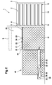
- FIGS. 3a-g The deck oven 1 according to FIGS. 1 and 2 will now be described with reference to a typical loading process with reference to the FIGS. 3a-g explained in more detail. It was for reasons of clarity in the FIGS. 3a-g dispensed with the representation of the protective grid 40 and the unloading device 9.
- FIG. 3a is the baking chamber flap 5 at the front baking chamber opening 4 of that baking chamber 2, which is to be loaded with the dough pieces 50, opened. Furthermore, the loader table 21 is moved to such a vertical height that the baking tray 10 can be pulled onto the loader table 21. For this purpose, the conveyor chain 23 of the horizontal conveyor unit 22 is moved so that the coupling element 24 can engage with its actuator 25 in the recess of the first coupling portion 11 of the baking tray 10.
- dough pieces 50 are already on the loading device 32 of the feeder 30 or are transferred from the feeder 35 to the loading device 32 by operating the conveyor belt of the feeder 35 and the loader belt 33 in parallel. Further dough pieces 50 are fed to the feeder 35 via a tray 51.
- the tray 51 with the other dough pieces 50 is inserted into the feeder 35.
- the dough pieces 50 are crawled up by the conveyor belt of the feeder 35.
- the loading table 21 is moved vertically such that the baking tray carrier 10 located thereon is aligned for insertion into the baking tray carrier receptacle 31 of the loading device 30.
- the conveyor chain 23 of the horizontal conveyor unit 22 is moved so that the coupling element 24 can engage with its actuator 25 in the recess of the further coupling portion 12 of the baking tray 10. Meanwhile, all the dough pieces 50 are crawled up from the tray 51 by the feeder 35.
- the baking tray 10 is inserted through the horizontal conveyor unit 22 in the baking stock carrier receptacle 31 of the feeder 30.
- the previously crawled dough pieces 50 are transferred from the feeding device 35 to the loader belt 33 of the loading device 32.
- the now empty tray 51 is removed.
- the baking tray carrier 10 is again pulled out of the baking tray carrier receptacle 31 onto the loading table 21 by the horizontal conveying unit 22.
- the loader belt 33 of the loading device 32 is moved at such a speed that the dough pieces 50 are transferred from the loader belt 33 to the baking tray 10 without the dough pieces thereby experiencing a speed change.
- the end of this loading process is in FIG. 3e shown. During the loading process - as well as in FIG. 3e to see - already more dough pieces 50 are abandoned on the feeder 35.
- the loader table 21 is moved with the thereon, now loaded with dough pieces baking tray carrier 10 back to the level of the baking chamber 2, from which the baking tray 10 was previously pulled out.
- the horizontal conveying unit 22 is again moved so that the actuator 25 engages in the recess of the first coupling portion 11 of the baking tray 10. The corresponding is in FIG. 3f shown.
- the baking tray 10 as in FIG. 3g shown, pushed back into the baking chamber 2.
- the baking chamber flap 5 is closed and the dough pieces 50 on the baking tray 10 are baked in the baking chamber 2.
Landscapes
- Life Sciences & Earth Sciences (AREA)
- Engineering & Computer Science (AREA)
- Food Science & Technology (AREA)
- Manufacturing And Processing Devices For Dough (AREA)
Applications Claiming Priority (1)
| Application Number | Priority Date | Filing Date | Title |
|---|---|---|---|
| DE102015217321.6A DE102015217321A1 (de) | 2015-09-10 | 2015-09-10 | Etagenofen mit automatisierter Beschickung |
Publications (1)
| Publication Number | Publication Date |
|---|---|
| EP3141121A1 true EP3141121A1 (fr) | 2017-03-15 |
Family
ID=56896410
Family Applications (1)
| Application Number | Title | Priority Date | Filing Date |
|---|---|---|---|
| EP16188086.9A Withdrawn EP3141121A1 (fr) | 2015-09-10 | 2016-09-09 | Four a etages dote d'un dispositif de chargement automatise |
Country Status (2)
| Country | Link |
|---|---|
| EP (1) | EP3141121A1 (fr) |
| DE (1) | DE102015217321A1 (fr) |
Cited By (2)
| Publication number | Priority date | Publication date | Assignee | Title |
|---|---|---|---|---|
| CN109008610A (zh) * | 2018-10-19 | 2018-12-18 | 环球炉业(惠州)有限公司 | 一种自动蒸炉系统 |
| EP3527894A1 (fr) * | 2018-02-20 | 2019-08-21 | Miele & Cie. KG | Procédé de fonctionnement d'un appareil de cuisson et appareil de cuisson |
Citations (3)
| Publication number | Priority date | Publication date | Assignee | Title |
|---|---|---|---|---|
| DE9419075U1 (de) * | 1994-07-15 | 1995-02-16 | Daub, Franz, 22523 Hamburg | Anordnung zum Umsetzen von Teigstücken von einem Gärwagen in einen Backofen |
| DE29718005U1 (de) * | 1997-10-10 | 1999-02-04 | Daub Hamburg GmbH, 22525 Hamburg | Anordnung zum Belegen des Ausziehherds eines Backofens |
| DE102007016931A1 (de) * | 2007-04-05 | 2008-10-09 | Miwe Michael Wenz Gmbh | Beschickungsanlage für Etagenbackofen |
Family Cites Families (1)
| Publication number | Priority date | Publication date | Assignee | Title |
|---|---|---|---|---|
| DE102012212855A1 (de) * | 2012-07-23 | 2014-01-23 | Daub Backtechnik Gmbh | Verfahren und Anlage zur zeitlich begrenzten Aufnahme von Backgutträgern |
-
2015
- 2015-09-10 DE DE102015217321.6A patent/DE102015217321A1/de not_active Withdrawn
-
2016
- 2016-09-09 EP EP16188086.9A patent/EP3141121A1/fr not_active Withdrawn
Patent Citations (3)
| Publication number | Priority date | Publication date | Assignee | Title |
|---|---|---|---|---|
| DE9419075U1 (de) * | 1994-07-15 | 1995-02-16 | Daub, Franz, 22523 Hamburg | Anordnung zum Umsetzen von Teigstücken von einem Gärwagen in einen Backofen |
| DE29718005U1 (de) * | 1997-10-10 | 1999-02-04 | Daub Hamburg GmbH, 22525 Hamburg | Anordnung zum Belegen des Ausziehherds eines Backofens |
| DE102007016931A1 (de) * | 2007-04-05 | 2008-10-09 | Miwe Michael Wenz Gmbh | Beschickungsanlage für Etagenbackofen |
Cited By (3)
| Publication number | Priority date | Publication date | Assignee | Title |
|---|---|---|---|---|
| EP3527894A1 (fr) * | 2018-02-20 | 2019-08-21 | Miele & Cie. KG | Procédé de fonctionnement d'un appareil de cuisson et appareil de cuisson |
| CN109008610A (zh) * | 2018-10-19 | 2018-12-18 | 环球炉业(惠州)有限公司 | 一种自动蒸炉系统 |
| CN109008610B (zh) * | 2018-10-19 | 2024-01-23 | 环球炉业(惠州)有限公司 | 一种自动蒸炉系统 |
Also Published As
| Publication number | Publication date |
|---|---|
| DE102015217321A1 (de) | 2017-03-16 |
Similar Documents
| Publication | Publication Date | Title |
|---|---|---|
| DE102008015278B4 (de) | Palettiervorrichtung | |
| DE102012205812A1 (de) | Warenlagersystem für ein Transportfahrzeug | |
| DE102012218394A1 (de) | Vorrichtung zum Lagern von Waren, insbesondere Arzneimitteln | |
| EP2141998A1 (fr) | Installation de chargement pour des fours de cuisson à étages | |
| DE102013014631A1 (de) | Tabletttransportvorrichtung und Verfahren zur kontinuierlichen Förderung mehrerer Tabletts unter Einsatz einer Tabletttransportvorrichtung | |
| EP0827692B1 (fr) | Dispositif et procédé pour transporter une pluralité de plateaux à travers une chambre de fermentation ou four | |
| EP3141121A1 (fr) | Four a etages dote d'un dispositif de chargement automatise | |
| EP2689664B1 (fr) | Procédé et installation pour la réception limitée dans le temps de supports de produits cuits | |
| EP3183070B1 (fr) | Procédé et installation pour trier des objets | |
| EP1820400A2 (fr) | Dispositif de chargement | |
| EP3141125A1 (fr) | Four a etages comprenant un chariot de chargement | |
| DE2459479A1 (de) | Baeckereibetriebsverfahren | |
| DE2016220C3 (de) | Bedienungseinrichtung für mehretagige Backöfen. Aiwi: Werner & Pfleiderer, 7000 Stuttgart | |
| EP0816260A1 (fr) | Magazin à rayonnage déplaçable | |
| DE2558340C2 (de) | Vorrichtung zum Stapeln von blockförmigen Gütern | |
| DE202005014103U1 (de) | Vorrichtung zum Handhaben von gefüllten Speisentabletts | |
| AT389983B (de) | Einschiesswagen | |
| DE102014205583A1 (de) | Regalbediengerät für ein Regallager, Regallager mit einem derartigen Regalbediengerät sowie Verfahren zum Ein-/Auslagern von Kleiderstangen in ein bzw. aus einem derartigen Regallager | |
| EP2308310A1 (fr) | Dispositif de chargement pour fours de cuisson | |
| DE102010040422B4 (de) | Lader für Wagenofen | |
| DE102004031857A1 (de) | Verfahren und Anlage zum Portionieren von Mahlzeiten auf Serviertabletts sowie Arbeitsstation hierfür | |
| DE19707716C2 (de) | Vorrichtung zur Bearbeitung von Lebensmitteln | |
| DE1556734C3 (de) | Einrichtung zum Be- und Entladen von Etagengestellen, insbesondere von Mehretagen-Käse norden | |
| DE2222599C3 (de) | Vorrichtung zum selbsttätigen Beladen eines Hordenwagens | |
| DE2725102C3 (de) | Vorrichtung zum Bestrahlen von Stuckgut |
Legal Events
| Date | Code | Title | Description |
|---|---|---|---|
| PUAI | Public reference made under article 153(3) epc to a published international application that has entered the european phase |
Free format text: ORIGINAL CODE: 0009012 |
|
| STAA | Information on the status of an ep patent application or granted ep patent |
Free format text: STATUS: THE APPLICATION HAS BEEN PUBLISHED |
|
| AK | Designated contracting states |
Kind code of ref document: A1 Designated state(s): AL AT BE BG CH CY CZ DE DK EE ES FI FR GB GR HR HU IE IS IT LI LT LU LV MC MK MT NL NO PL PT RO RS SE SI SK SM TR |
|
| AX | Request for extension of the european patent |
Extension state: BA ME |
|
| RIN1 | Information on inventor provided before grant (corrected) |
Inventor name: RANFT, ANDREAS Inventor name: FLISZAR, GUENTHER Inventor name: OTTENBERG, MARKUS |
|
| STAA | Information on the status of an ep patent application or granted ep patent |
Free format text: STATUS: REQUEST FOR EXAMINATION WAS MADE |
|
| 17P | Request for examination filed |
Effective date: 20170914 |
|
| RBV | Designated contracting states (corrected) |
Designated state(s): AL AT BE BG CH CY CZ DE DK EE ES FI FR GB GR HR HU IE IS IT LI LT LU LV MC MK MT NL NO PL PT RO RS SE SI SK SM TR |
|
| GRAP | Despatch of communication of intention to grant a patent |
Free format text: ORIGINAL CODE: EPIDOSNIGR1 |
|
| STAA | Information on the status of an ep patent application or granted ep patent |
Free format text: STATUS: GRANT OF PATENT IS INTENDED |
|
| INTG | Intention to grant announced |
Effective date: 20190522 |
|
| STAA | Information on the status of an ep patent application or granted ep patent |
Free format text: STATUS: THE APPLICATION HAS BEEN WITHDRAWN |
|
| 18W | Application withdrawn |
Effective date: 20190927 |