EP3141126A1 - Installation de traitement de pate - Google Patents
Installation de traitement de pate Download PDFInfo
- Publication number
- EP3141126A1 EP3141126A1 EP16186598.5A EP16186598A EP3141126A1 EP 3141126 A1 EP3141126 A1 EP 3141126A1 EP 16186598 A EP16186598 A EP 16186598A EP 3141126 A1 EP3141126 A1 EP 3141126A1
- Authority
- EP
- European Patent Office
- Prior art keywords
- dough
- processing
- conveying
- processing unit
- conveying direction
- Prior art date
- Legal status (The legal status is an assumption and is not a legal conclusion. Google has not performed a legal analysis and makes no representation as to the accuracy of the status listed.)
- Withdrawn
Links
- 238000012545 processing Methods 0.000 title claims abstract description 93
- 238000003754 machining Methods 0.000 claims description 8
- 238000005520 cutting process Methods 0.000 claims description 7
- 230000007246 mechanism Effects 0.000 claims description 4
- 238000004080 punching Methods 0.000 description 9
- 238000004898 kneading Methods 0.000 description 3
- 238000012546 transfer Methods 0.000 description 3
- 238000000034 method Methods 0.000 description 2
- 230000001360 synchronised effect Effects 0.000 description 2
- 230000003213 activating effect Effects 0.000 description 1
- 238000013459 approach Methods 0.000 description 1
- 230000005540 biological transmission Effects 0.000 description 1
- 239000000470 constituent Substances 0.000 description 1
- 235000013312 flour Nutrition 0.000 description 1
- 238000009940 knitting Methods 0.000 description 1
- 238000012544 monitoring process Methods 0.000 description 1
- 230000010355 oscillation Effects 0.000 description 1
- 238000002360 preparation method Methods 0.000 description 1
- 238000007493 shaping process Methods 0.000 description 1
Images


Classifications
-
- A—HUMAN NECESSITIES
- A21—BAKING; EDIBLE DOUGHS
- A21C—MACHINES OR EQUIPMENT FOR MAKING OR PROCESSING DOUGHS; HANDLING BAKED ARTICLES MADE FROM DOUGH
- A21C11/00—Other machines for forming the dough into its final shape before cooking or baking
- A21C11/02—Embossing machines
-
- A—HUMAN NECESSITIES
- A21—BAKING; EDIBLE DOUGHS
- A21C—MACHINES OR EQUIPMENT FOR MAKING OR PROCESSING DOUGHS; HANDLING BAKED ARTICLES MADE FROM DOUGH
- A21C11/00—Other machines for forming the dough into its final shape before cooking or baking
- A21C11/10—Other machines for forming the dough into its final shape before cooking or baking combined with cutting apparatus
Definitions
- the invention relates to a dough processing plant with a processing device for processing on a dough conveyor conveyed dough pieces with a processing unit.
- Such a dough processing plant is for example from the EP 1 600 058 A2 known.
- the EP 1 853 117 B1 discloses a method for making dough pieces from dough strands and a device therefor.
- the EP 1 296 137 A2 discloses a measuring method for determining and monitoring dough quality for automatic dough processing.
- a processing unit driven in the conveying direction during the stump processing with the dough piece to be processed ie a processing unit moving along with the dough piece during stump processing, makes it possible to produce a stump processing during a processing operation Extend the period.
- the Stüpfelvorgang itself can take place during this period without a relative movement of the dough piece to the stump processing unit takes place along the conveying direction.
- the relative movement between the dough piece and the stump processing unit can therefore take place exclusively along a punching direction, that is to say along a machining direction which can be perpendicular to the conveying direction. Even with a higher conveying speed, the same speed can always be achieved in the result, since the moving processing unit allows a longer stoppage period.
- a correspondingly extended period is available for a stump processing, in which the stump processing unit moves synchronously to the dough piece.
- the dough conveyor can promote the dough pieces to be processed in the conveyor with a predetermined, constant conveying speed. A timing of a dough processing such that the dough conveyor is temporarily stopped during a processing cycle can be avoided. This increases the throughput of the dough processing plant.
- the conveyor may be designed so that dough pieces are conveyed directly thereto. Alternatively, the conveyor can be designed so that over this dough pieces, such as dough dishes, are promoted.
- the conveyor may be configured to convey the dough pieces over a portion of their entire conveying path.
- the conveyor can be designed as an endless circulating conveyor.
- the conveyor can be designed as a conveyor belt.
- An embodiment according to claim 2 allows a high throughput of the dough processing plant.
- the dough processing plant can be made multi-row, for example, six-row, eight-row or ten-row.
- Two drives according to claim 3 have been found to be particularly suitable for specifying a trajectory of the moving processing unit.
- a machining depth and a machining time can be set independently of each other.
- the drives may have drive motors that are designed as servomotors.
- a crank mechanism according to claim 4 has been found to be particularly suitable for specifying drive movement components of the movement path of the processing unit. There may be several, for example, two crank mechanisms for driving the processing unit may be provided. At least one of the drives of the dough processing plant can alternatively or additionally be designed as a vibratory drive.
- a varying rotational speed according to claim 5 makes it possible to predetermine a time course of the movement path of the processing unit during the respective machining operation. This can be done in the form of an electronic curve. After processing can in this way the processing unit z. B. are transferred very quickly counter to the conveying direction in a starting position for processing the next dough.
- a cutting processing unit may be configured separately from the punch processing unit.
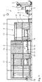
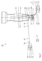
- the schematic structure of an in Fig. 1 illustrated embodiment of a dough processing plant 1 is basically from the EP 1 600 058 A2 known.
- the dough processing equipment 1 has a base frame 1a and comprises a kneader 2 for kneading dough.
- the kneading device 2 has a lifting and pivoting trough 3, which in Fig. 1 is shown in both a kneading and in a raised and pivoted delivery position. In the delivery position of the trough 3 is below this a feed hopper 4 a portioning and rotary device 5.
- the portioning and rotary device 5 comprises a round knitting station 6. This is by a multi-beam transfer conveyor belt 7 with a modular constructed fermenting and shaping device 8 connected.
- the hanger conveyor 10 comprises a plurality of hanger, not shown, for receiving dough, in particular dough pieces.
- the hangers are connected to a conveyor chain 11 which is guided endlessly circulating over a plurality of pulleys 12.
- conveying the conveyor chain 11 runs in sub-modules 13, 14, 15 in a substantially clockwise order.
- a stamping station 16 is provided in the sub-module 15.
- the submodule 15 forms a constituent part of a sprinkling and posthardening device 17.
- the dough pieces are transported along the conveying direction 9 by means of a section of a driven conveyor belt 18, which is preferably designed in multiple lanes.
- the conveyor belt 18 is an example of a dough conveyor for conveying the dough pieces in the conveying direction 9.
- the conveyor belt 18 conveys the dough pieces to be processed in the conveying direction 9 at a predetermined, constant conveying speed.
- the dough pieces are received in Teiglingschalen 18 a, which are taken from the conveyor belt 18 and move with this at the predetermined, constant conveying speed in the conveying direction 9.
- the dough pieces in the embodiment of the dough processing system 1 shown in the conveying direction 9 pass through a plurality of processing stations, to which a stamping station 19 belongs, which in the Fig. 1 is shown very schematically.
- the dough processing equipment 1 is designed to carry out at least sixty-five operations per minute and can be more than sixty-five operations per minute, more than seventy Perform machining operations per minute and also more than eighty machining operations per minute.
- one or more of the processing stations shown schematically may be omitted or replaced by a comparable station.
- the dough pieces arrive after the conveyor belt section 18 on a section of a further driven conveyor belt 20.
- the dough pieces During conveyance on the conveyor belt 20 in the conveying direction 9, the dough pieces pass through a flouring device 21 according to the invention, through which the dough pieces are selectively sprinkled with flour.
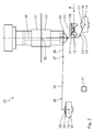
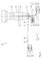
- the stub device 22 represents an example of a processing device of the dough processing plant 1 for processing the conveyed on the conveyor belt 18 dough pieces with a processing unit.
- a processing unit is used in the stub device 22 is a Stüpfelech 23
- the a stub tool 24 for staking the dough piece such as a Kaiserstüpfler, has at its lower end.
- the punching unit 23 is designed in such a way that during processing, that is to say during the stamping, with the dough piece to be processed relative to the base frame 1 a, which in the Fig. 2 is indicated by two frame strips shown broken, is driven driven in the conveying direction 9.
- the drive motors 27, 28 are designed as servomotors.
- the drive 25 is the actual Stüpfelantrieb the Stüpfel submitted 22 and provides a vertical movement component of the Stüpfeltician 23 relative to the Teiglingschale 18 a.
- the further drive 26 constitutes a ride-on drive, which drives the punching unit 23 in the conveying direction 9 synchronized with the dough-sheeting 18a during the stamping with a travel speed which corresponds to the conveying speed of the conveyor belt 18.
- the Stüpfelantrieb 25 is designed as a rocker, so as a vibratory drive.
- the Mitfahrantrieb 26 is designed as a crank mechanism.
- An amplitude of the oscillating drive 25 can be preset. About the oscillation amplitude can specify a processing depth and in particular a Stüpfelianae.
- the processing depth on the one hand and the processing time on the other hand can be set independently.
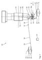
- a crank 29 of the stump drive 25 is rotatably connected to a drive shaft 30 of the drive motor 27.
- the crank 29 is pivotally connected to a transmission lever 31, which in turn is connected via a pivot joint 32 with a base body 33 of the Stüpfelech 23.
- the drive shaft 30 extends parallel to the hinge axes of the linkages between the levers 29 and 31 on the one hand and to a pivot axis of the pivot joint 32 on the other.
- a drive shaft 34 of the drive motor 28 is rotatably connected to a crank 35 of the ride-driving 26.
- the crank 35 is pivotally connected to a ride-transfer lever 36, which in turn is connected via a ride-on swivel joint 37 with a fixedly mounted on the base 33 boom 38 of the punch unit 23.
- the drive shaft 34 extends parallel to the hinge axes of the linkages between the levers 35, 36 on the one hand and to a pivot axis of the pivot joint 37 on the other.
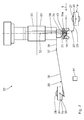
- the Fig. 2 and 3 show a preparation period of the staking, in which the punch tool 24 approaches in the vertical direction of the dough dish 18a. From the momentary position to Fig. 4 A central longitudinal axis 39 of the punch tool 24 is aligned with a central longitudinal axis 40 of the dough sheet shell 18a. Between the current positions after the Fig. 4 and the Fig. 8 the stubbing takes place. During this period of processing, the punching unit 23 moves along with the dough sheet tray 18a in the conveying direction 9 at the predetermined conveying speed of the conveyor belt 18. This ride-on movement with the conveying speed of the conveyor belt 18 is predetermined via the ride-on drive 26.
- the punching tool 24 As soon as after stubbing, driven by the stump drive 25, the punching tool 24 has a sufficiently large vertical distance to the dough dish 18a and thus to the diced dough piece, the punching tool is no longer driven along with the dough dish 18a, but very quickly counter to the conveying direction 9 towards the starting position Beginning of the stubbing in cooperation with the next dough bowl 18a spent. This movement counter to the conveying direction 9 occurs at a significantly higher speed than the absolute amount of the conveying speed of the conveyor belt 18. The processing sequence according to the Fig. 2 to 9 is then repeated for the processing of the dough in the next Teiglingschale 18 a.
- the drive shaft 30 reverses its direction of rotation during processing, depending on whether the punch tool 24 is lowered in the direction of the dough dish 18a or lifted in the opposite direction thereof.
- the movement path of the punching tool 24 is brought about relative to the dough dish 18a in the form of an electronic curve.
- a traveling cutting device as a further possible processing device with corresponding drives.
- the Mitfahrantrieb such a cutting device can be carried out the same as the Mitfahrantrieb 26.
- a cutting drive of such a cutting device can be performed according to the Stüpfelantrieb the Stüpfel worn 22.
- a drive of the conveyor belts 18 and 20 and the Stüpfelantrieb 25 and the ride-driving 26 are controlled by a common control device 41 of the dough processing plant 1, which is shown schematically in the drawing. Details of a synchronization of the respective processing unit for dough conveying can be specified via the control device 41, in particular the number of processing operations per minute or a ride-in period during which the processing unit moves synchronized with the dough piece in the conveying speed.
Landscapes
- Life Sciences & Earth Sciences (AREA)
- Engineering & Computer Science (AREA)
- Food Science & Technology (AREA)
- Manufacturing And Processing Devices For Dough (AREA)
Applications Claiming Priority (1)
| Application Number | Priority Date | Filing Date | Title |
|---|---|---|---|
| DE102015217192.2A DE102015217192A1 (de) | 2015-09-09 | 2015-09-09 | Teigbearbeitungsanlage |
Publications (1)
| Publication Number | Publication Date |
|---|---|
| EP3141126A1 true EP3141126A1 (fr) | 2017-03-15 |
Family
ID=56853478
Family Applications (1)
| Application Number | Title | Priority Date | Filing Date |
|---|---|---|---|
| EP16186598.5A Withdrawn EP3141126A1 (fr) | 2015-09-09 | 2016-08-31 | Installation de traitement de pate |
Country Status (2)
| Country | Link |
|---|---|
| EP (1) | EP3141126A1 (fr) |
| DE (1) | DE102015217192A1 (fr) |
Cited By (1)
| Publication number | Priority date | Publication date | Assignee | Title |
|---|---|---|---|---|
| DE102023105536A1 (de) * | 2023-03-07 | 2024-09-12 | Fritsch Bakery Technologies GmbH & Co. KG | Teigverarbeitungsanlage mit Produktprogrammweiterleitung |
Citations (6)
| Publication number | Priority date | Publication date | Assignee | Title |
|---|---|---|---|---|
| US5006358A (en) * | 1988-05-09 | 1991-04-09 | Ribio Manuel J | Method of making tortillas |
| WO1998023168A1 (fr) * | 1996-11-27 | 1998-06-04 | Mars, Incorporated | Formage par ultrasons de confiseries |
| EP1296137A2 (fr) | 2001-09-25 | 2003-03-26 | A. FRITSCH GMBH & CO. KG | La mesure de pâte pour surveiller et régler la qualité de pâte dans le traitement automatique de pâte |
| US20040191378A1 (en) * | 2003-03-25 | 2004-09-30 | Golby Adrian Barry | System and method for processing tortillas |
| EP1600058A2 (fr) | 2004-05-29 | 2005-11-30 | Neuenkirchener Maschinenfabrik Emil Kemper GmbH | Procédé et dispositif pour former un anneau de pâte prêt à cuire et sans connexion, et procédé de fabrication d'un produit de pâtisserie en forme d'anneau à partir d'un anneau de pâte ainsi préformé |
| EP1853117B1 (fr) | 2005-02-25 | 2011-03-23 | Fritsch GmbH | Procede pour produire des ebauches de pates enroulees a partir de bandes de pates et dispositif destine a produire mecaniquement les produits en pate enroulee |
-
2015
- 2015-09-09 DE DE102015217192.2A patent/DE102015217192A1/de not_active Ceased
-
2016
- 2016-08-31 EP EP16186598.5A patent/EP3141126A1/fr not_active Withdrawn
Patent Citations (6)
| Publication number | Priority date | Publication date | Assignee | Title |
|---|---|---|---|---|
| US5006358A (en) * | 1988-05-09 | 1991-04-09 | Ribio Manuel J | Method of making tortillas |
| WO1998023168A1 (fr) * | 1996-11-27 | 1998-06-04 | Mars, Incorporated | Formage par ultrasons de confiseries |
| EP1296137A2 (fr) | 2001-09-25 | 2003-03-26 | A. FRITSCH GMBH & CO. KG | La mesure de pâte pour surveiller et régler la qualité de pâte dans le traitement automatique de pâte |
| US20040191378A1 (en) * | 2003-03-25 | 2004-09-30 | Golby Adrian Barry | System and method for processing tortillas |
| EP1600058A2 (fr) | 2004-05-29 | 2005-11-30 | Neuenkirchener Maschinenfabrik Emil Kemper GmbH | Procédé et dispositif pour former un anneau de pâte prêt à cuire et sans connexion, et procédé de fabrication d'un produit de pâtisserie en forme d'anneau à partir d'un anneau de pâte ainsi préformé |
| EP1853117B1 (fr) | 2005-02-25 | 2011-03-23 | Fritsch GmbH | Procede pour produire des ebauches de pates enroulees a partir de bandes de pates et dispositif destine a produire mecaniquement les produits en pate enroulee |
Cited By (1)
| Publication number | Priority date | Publication date | Assignee | Title |
|---|---|---|---|---|
| DE102023105536A1 (de) * | 2023-03-07 | 2024-09-12 | Fritsch Bakery Technologies GmbH & Co. KG | Teigverarbeitungsanlage mit Produktprogrammweiterleitung |
Also Published As
| Publication number | Publication date |
|---|---|
| DE102015217192A1 (de) | 2017-03-09 |
Similar Documents
| Publication | Publication Date | Title |
|---|---|---|
| EP0635340B1 (fr) | Dispositif automatique de coupe | |
| EP2226170B1 (fr) | Cadres de chaînes de guidage pour trancheuse d'aliments automatique | |
| EP0226925B1 (fr) | Dispositif pour couper des portions | |
| DE1964331B2 (de) | Vorrichtung zum Herstellen von Handschuhen aus Latex | |
| DE2116632A1 (de) | Vorrichtung zum aufeinanderfolgenden Fördern von kleinen, länglichen Gegenständen bzw. Werkstücken | |
| EP3670400A1 (fr) | Installation de mise en uvre et procédé de mise en uvre | |
| EP3141126A1 (fr) | Installation de traitement de pate | |
| DE3900414C2 (fr) | ||
| EP3649863B1 (fr) | Benne élévatrice avec dispositif de sortie pour masses d'aliments compacts, en particulier de masses pour barres ou pâtes à biscuits | |
| DE1215073B (de) | Selbsttaetig arbeitende Baeckereianlage zur Herstellung von Backwaren, insbesondere von Broten und Broetchen | |
| DE3700091C1 (en) | Dough-plaiting apparatus | |
| EP0899197A2 (fr) | Procédé et dispositif de répartition d'un flot de produits | |
| EP1372400A2 (fr) | Dispositif pour former une bande de pate | |
| DE19831253A1 (de) | Verfahren und Vorrichtung zur maschinellen Herstellung von Manti-Teigwaren | |
| EP2298078A2 (fr) | Dispositif pour le pétrissage de portions de pâte | |
| DE2249383C3 (de) | Teigbearbeitungsanlage | |
| DE2136053B2 (de) | Maschine zum Herstellen von Schichtkeksen | |
| EP2193725B1 (fr) | Unité de transport et dispositif d'épluchage pour produit à éplucher étendu en longueur | |
| DE202009012319U1 (de) | Vorrichtung zum Belegen zumindest eines Abschnitts eines Lebensmittels | |
| EP1767475B1 (fr) | Dispositif pour pousser des articles d'un convoyeur à bande à un autre | |
| EP3078270A1 (fr) | Dispositif de depot continu de pate repliee sur un moyen de transport | |
| EP2225946A2 (fr) | Dispositif de traitement de produits alimentaires | |
| DE1258362B (de) | Vorrichtung zum UEbergeben von auf Gaerdielen herangefuehrten Wirklingen auf ein nachgeschaltetes Backband eines Backofens | |
| CH670933A5 (fr) | ||
| DE2315770C3 (de) | Vorrichtung zum Fördern und Ausrichten von Eiern sowie zum Überführen der Eier in Greiferaggregate einer Eierknickmaschine |
Legal Events
| Date | Code | Title | Description |
|---|---|---|---|
| PUAI | Public reference made under article 153(3) epc to a published international application that has entered the european phase |
Free format text: ORIGINAL CODE: 0009012 |
|
| AK | Designated contracting states |
Kind code of ref document: A1 Designated state(s): AL AT BE BG CH CY CZ DE DK EE ES FI FR GB GR HR HU IE IS IT LI LT LU LV MC MK MT NL NO PL PT RO RS SE SI SK SM TR |
|
| AX | Request for extension of the european patent |
Extension state: BA ME |
|
| 17P | Request for examination filed |
Effective date: 20170914 |
|
| RBV | Designated contracting states (corrected) |
Designated state(s): AL AT BE BG CH CY CZ DE DK EE ES FI FR GB GR HR HU IE IS IT LI LT LU LV MC MK MT NL NO PL PT RO RS SE SI SK SM TR |
|
| 17Q | First examination report despatched |
Effective date: 20190123 |
|
| STAA | Information on the status of an ep patent application or granted ep patent |
Free format text: STATUS: THE APPLICATION HAS BEEN WITHDRAWN |
|
| 18W | Application withdrawn |
Effective date: 20190624 |