EP3141165B1 - Packungszuführ-/-ablösemechanismus für getränkebrauvorrichtung - Google Patents
Packungszuführ-/-ablösemechanismus für getränkebrauvorrichtung Download PDFInfo
- Publication number
- EP3141165B1 EP3141165B1 EP14891489.8A EP14891489A EP3141165B1 EP 3141165 B1 EP3141165 B1 EP 3141165B1 EP 14891489 A EP14891489 A EP 14891489A EP 3141165 B1 EP3141165 B1 EP 3141165B1
- Authority
- EP
- European Patent Office
- Prior art keywords
- frame
- capsule
- guiding
- guiding blocks
- jaw
- Prior art date
- Legal status (The legal status is an assumption and is not a legal conclusion. Google has not performed a legal analysis and makes no representation as to the accuracy of the status listed.)
- Active
Links
Images


Classifications
-
- A—HUMAN NECESSITIES
- A47—FURNITURE; DOMESTIC ARTICLES OR APPLIANCES; COFFEE MILLS; SPICE MILLS; SUCTION CLEANERS IN GENERAL
- A47J—KITCHEN EQUIPMENT; COFFEE MILLS; SPICE MILLS; APPARATUS FOR MAKING BEVERAGES
- A47J31/00—Apparatus for making beverages
- A47J31/24—Coffee-making apparatus in which hot water is passed through the filter under pressure, i.e. in which the coffee grounds are extracted under pressure
- A47J31/34—Coffee-making apparatus in which hot water is passed through the filter under pressure, i.e. in which the coffee grounds are extracted under pressure with hot water under liquid pressure
- A47J31/36—Coffee-making apparatus in which hot water is passed through the filter under pressure, i.e. in which the coffee grounds are extracted under pressure with hot water under liquid pressure with mechanical pressure-producing means
- A47J31/3604—Coffee-making apparatus in which hot water is passed through the filter under pressure, i.e. in which the coffee grounds are extracted under pressure with hot water under liquid pressure with mechanical pressure-producing means with a mechanism arranged to move the brewing chamber between loading, infusing and ejecting stations
- A47J31/3623—Cartridges being employed
- A47J31/3638—Means to eject the cartridge after brewing
-
- A—HUMAN NECESSITIES
- A47—FURNITURE; DOMESTIC ARTICLES OR APPLIANCES; COFFEE MILLS; SPICE MILLS; SUCTION CLEANERS IN GENERAL
- A47J—KITCHEN EQUIPMENT; COFFEE MILLS; SPICE MILLS; APPARATUS FOR MAKING BEVERAGES
- A47J31/00—Apparatus for making beverages
- A47J31/24—Coffee-making apparatus in which hot water is passed through the filter under pressure, i.e. in which the coffee grounds are extracted under pressure
- A47J31/34—Coffee-making apparatus in which hot water is passed through the filter under pressure, i.e. in which the coffee grounds are extracted under pressure with hot water under liquid pressure
- A47J31/36—Coffee-making apparatus in which hot water is passed through the filter under pressure, i.e. in which the coffee grounds are extracted under pressure with hot water under liquid pressure with mechanical pressure-producing means
- A47J31/3604—Coffee-making apparatus in which hot water is passed through the filter under pressure, i.e. in which the coffee grounds are extracted under pressure with hot water under liquid pressure with mechanical pressure-producing means with a mechanism arranged to move the brewing chamber between loading, infusing and ejecting stations
- A47J31/3623—Cartridges being employed
- A47J31/3633—Means to perform transfer from a loading position to an infusing position
Definitions
- the present invention relates to a capsules delivery and rejection mechanism in a beverage extraction device, and the beverage extraction device mainly refers to a coffeemaker.
- the existing coffeemaker generally has a function of automatic capsule rejection for ease of operation.
- a Chinese Utility Model Patent CN201044719Y Patent No.: 200720110811.2
- titled “Capsule Automatically Rejecting Mechanism of Coffeemaker” disclosed a coffeemaker which has a simple and rational structure, is stable and convenient in operation and feels good in touching is invented.
- a spring is provided inside the chamber of the first frame. The forgoing coffeemaker structure is somewhat improved.
- a capsule dropping mechanism comprising: a housing; a first frame having a chamber for holding a capsule with a circular edge; a second frame; two jaws, characterized in that notches for receiving clamp portions are formed on left and right sides of a rear end surface of the first frame; two groups of guiding grooves for guiding a front shaft and a rear shaft of the jaws are provided on the housing; in a state in which the first frame and the second frame are totally closed, the clamp portions on the two jaws are located within the notch of the first frame; and in a state in which the second frame moves backward, the limiting portions on the two jaws move backward along with the second frame and come into contact with the circular edge of the capsule to drive the capsule to move backward and out of the chamber.
- the driving of the clamp portions can push the capsule from the chamber of the
- two groups guiding grooves for guiding the front shaft and the rear shaft of the jaws are provided on the housing, the jaws move forward along with the second frame during the whole capsule delivery process, and there is no idle stroke between the jaws and the second frame. Therefore, in order to completely deliver a capsule into the chamber and the guiding grooves can guide the jaws to open and close according to the requirement of capsule dropping, it is necessary to provide a large overall length for the guiding grooves.
- the guiding grooves include a straight rear groove, a straight front groove, a curved middle groove and a curved front groove, the straight front groove is in front of the straight rear groove and inclined outward, the curved middle groove is on the outer side of the straight rear groove, and the curved front groove and the straight front groove are separated by a second barrier. Accordingly, in the foregoing two patents, the overall length of the guiding grooves is large, and the working process of the coffeemaker is completed. Consequently, the length of the whole housing cannot be made small and the coffeemaker cannot be miniaturized.
- a technical problem to be solved by the present invention is to provide a novel capsule delivery and rejection mechanism for a beverage brewing device, which has a simpler and more rational structure and allows for reliable capsule delivery and rejection.
- the mechanism has a smaller overall size and is low in cost and easy to assemble.
- a capsule delivery and rejection mechanism in a beverage brewing device as defined in claim 1.
- Each guiding block may be arranged so that it is able to be deflected.
- an elastic mechanism for enabling the jaws to keep an inward clamping trend is provided on the second frame.
- the elastic mechanism enables the jaws to keep a clamping trend so as to make the jaws clamp the beverage capsule better, or to make the jaws to return to the original positions during the backward movement process so as to drive the beverage capsule.
- the functions of the elastic mechanism can be realized by a similar guide structure.
- the elastic mechanism is a torsion spring provided on a spindle at the rear end of the jaws.
- the torsion spring is easy to assemble.
- other elastic members such as a spring, can also be used.
- the capsule delivery and rejection mechanism characterized in that, a recess for receiving each jaw is respectively provided on the left and right sidewalls of the second frame, and the rear end of each jaw is located inside the recess; a first end of the torsion spring is hooked through a small hole formed on one jaw, while a second end of the torsion spring resists against the inner wall of the recess of the jaw.
- the recess restrains the deflection of each jaw, and ensures that each jaw is deflected within a rational range.
- slots are provided at the front ends of the jaws; the guiding blocks are inserted into the slots and rotatably connected into the slots.
- Upper and lower walls of the slots restrain the guiding blocks in the up-down direction, so that the deflection stability of the guiding blocks is ensured; when in the original positions, the rear end surfaces of the guiding blocks are in contact with the bottom surfaces of the slots.
- the contact of the guiding blocks with the bottom surfaces of the slots ensures that the guiding surfaces of the guiding blocks are deflected in an opposite direction under the squeezing of the sidewalls of the first frame, so that the guiding blocks can drive the jaws more stably to expand outward.
- a shaft is provided protruding on the upper and lower surfaces of each guiding block, and each jaw has two through holes respectively locating at the upper and lower sides of each slot for two ends of each shaft to pass through; the upper and lower end surfaces of the shafts are slopes, and the upper and lower inner walls of each slot are also slopes.
- Such a structure is convenient to mount the guiding blocks into the slots.
- the resetting mechanism is a stopping part which is provided on a housing sidewall and in stopping fit to the sidewalls of the guiding blocks in the state where the guiding blocks are turned over, the sidewall of the second frame moved backward to the guiding blocks comes into contact with the stopping part and continues to move backward, and the stopping part exerts a forward thrust onto the sidewalls of the guiding blocks to impel the guiding blocks to reset.
- This resetting mechanism completes the interference to the sidewalls of the guiding blocks through the stopping part.
- the resetting mechanism can also be a torsion spring mechanism.
- each guiding surface is a slope.
- the slopes can decompose a force acting on the guiding blocks into a larger and positive thrust acting on the guiding blocks.
- the larger thrust allows for the better deflection of the guiding blocks, and the deflected torsion and the arrangement of the slopes can reduce the friction between the guiding blocks and the sidewalls of the second frame, so that it is easier to push the second frame.
- an opening which runs through in an axial direction and allows the circular edge of the capsule to insert therein is formed at an inner end of the clamp portion, and the bottom surface of this opening is a cambered surface which is bent inward.
- This opening restrains the circular edge of the beverage capsule, and the inward bent bottom surface of the opening supports the circular edge of the capsule.
- the present invention has the following advantages: in a state where the first frame and the second frame are completely opened, the elastic mechanisms of the two jaws can hold a capsule when they are closed; in a state where the second frame is moved forward so that the capsule is partially located inside the chamber, the guiding surfaces of the guiding blocks come into contact with the sidewalls of the first frame and then continues to move forward, and each sidewall of the first frame has an outward force onto each guiding surface so as to make the two guiding blocks to be opened, so that the capsule is further pushed into the chamber; the second frame is further moved forward, so the first frame and the second frame are completely closed to form an extraction chamber, and the circular edge of the capsule is externally exposed out from the periphery of the front end surface of the second frame, so that the capsule loading is completed, and the rear end surface of the guiding blocks are located in the rear of the stepped surface on the first frame; subsequently, the second frame is moved backward, the stepped surface exerts a forward thrust to the rear end surfaces of
- the capsule delivery and rejection mechanism realizes the capsule delivery and rejection mainly by the mutual cooperation between the jaws, the guiding blocks and the first frame.
- the capsule delivery and rejection design is very skillful, and the primary complicated shaft-groove fitting structure is omitted in the whole structure, leading to simpler overall structure and manufacture process and low cost.
- Fig. 10 - Fig. 11 show a preferred embodiment of a capsule delivery and rejection mechanism for a beverage brewing device.
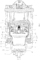
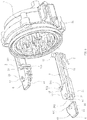
- the capsule delivery and rejection mechanism for a beverage brewing device comprises a housing 1 having a front portion, a back portion, a loading port 11, and a dropping port 12; a first frame 2 positioned inside the front portion of the housing 1, the first frame 2 having a left side, a right side, a chamber 21 for holding a capsule 4 with a circular edge 41, the first frame 2 further having a liquid discharge passage, the first frame 2 being integrated with the housing 1; a second frame 3 having a left side and a right side, disposed inside the back portion of the housing 1 and being movable forward and backward relative to the first frame 2 under the driving of a driving structure, the second frame 3 having a liquid intake passage; two jaws 5, each jaw 5 having a front end and a rear end, the rear end of each jaw respectively rotatably connected to the left and right sides of the second frame 3; two guiding blocks 6, sheet-shaped, each guiding block 6 being rotatably arranged at front of each jaw 5; and a resetting mechanism for resetting the
- a recess 31 for receiving each jaw 5 is respectively provided on the left and right sidewalls of the second frame 3, and the rear end of each jaw 5 is located inside the recess 31 and rotatably arranged at a rotating shaft 52 inside the recess 31, and an elastic mechanism for allowing the jaws 52 to keep an inward clamping trend is provided on the second frame 3.
- the elastic mechanism in this embodiment is a torsion spring 7 provided on the spindles 52 at the rear end of the jaws 5; a first end of the torsion spring 7 is hooked through a small hole 53 formed on one jaw 5, while a second end of the torsion spring 7 resists against the inner wall of the recess 31 of the jaw 5.
- each jaw 5 is a clamp portion 51 extending to the front of the second frame 3, the clamp portion 51 has a clamping opening capable of clamping the circular edge 41 of the capsule 4; an opening 512 which runs through in an axial direction and allows the circular edge 41 of the capsule 4 to insert therein is formed at an inner end of the clamp portion 51, and the bottom surface 513 of this opening 512 is a cambered surface which is bent inward.
- Each guiding block 6 has a rear end surface 62 and a guiding surface 61 at the inner side of each guiding block 6 which can be guided to open when the guiding surface 61 touching the sidewalls 22 of the first frame 2; each guiding surface 61 is a slope; the guiding blocks 6 can move forward with the jaws 5 from their original positions and touch the sidewalls 22 of the first frame 2, and then continue to move forward, at this time, each sidewall 22 of the first frame 2 has an outward force onto each guiding surface 61 so as to make the two guiding blocks 6 to be opened.
- Slots 54 are provided at the front ends of the jaws 5, the guiding blocks 6 are inserted into the slots 54 and rotatably connected into the slots 54; when in the original positions, the rear end faces of the guiding blocks 6 are in contact with the bottom surfaces of the slots 54.
- a shaft 63 is provided protruding on the upper and lower surfaces of each guiding block 6, and each jaw 5 has two through holes 55 respectively locating at the upper and lower sides of each slot 54 for two ends of each shaft 63 to pass through; the upper and lower end surfaces 631 of the shafts 63 are slopes, and the upper and lower inner walls 541 of each slot 54 are also slopes.
- An annual stepped surface 23 is provided on the periphery of the first frame 2, when the second frame 3 is closed with the first frame 2 and then move backward, the stepped surface 23 has a forward force onto the rear end surface 62 of each guiding block 6 to force each guiding block 6 to rotate outward.
- a stepped surface 23 is provided on an outer side of the first frame 2. In a state where the second frame 3 is closed and then moved backward, the stepped surface 23 exerts a forward thrust onto the rear end surfaces 62 of the guiding blocks 6 to force the guiding blocks 6 to rotate outward.
- each clamp portion 51 can touch with the circular edge 41 of the capsule 4, when each clamp portion 51 continues to move backward after touching with the circular edge 41 of the capsule; the rear end surface 511 of each clamp portion 51 will pull the circular edge 41 to carry the capsule 4 out from the chamber 21.
- the resetting mechanism is a stopping part 13 which is provided on a housing 1 sidewall and in stopping fit to the sidewalls 64 of the guiding blocks 6; in the state where the guiding blocks 6 are turned over, the sidewall 64 of the second frame 3 moved backward to the guiding blocks 6 comes into contact with the stopping part 13 and continues to move backward, and the stopping part 13 exerts a forward thrust onto the sidewalls 64 of the guiding blocks 6 to impel the guiding blocks 6 to reset.
- the operating process of the capsule delivery and rejection mechanism is as follows.
- Capsule loading As shown in Fig. 2 , the driving structure drives the second frame 3 to move backward to open, the two jaws 5 are closed and thus can hold the capsule 4, and the capsule 4 is loaded from the loading port 11 and placed between the two clamp portions, with the circular edge 41 of the capsule 4 being inserted from the slot 131 and supported on the bottom surface 132 of the slot 131.
- Capsule delivery As shown in Fig. 3 - Fig. 5 , the second frame 3 is moved forward, and since the capsule 4 is restrained between the clamp portions 51 at the front ends of the two jaws, the forward movement of the second frame 3 can drive the capsule and the jaws to move forward together; and in a state where the second frame 3 is moved forward so that the capsule 4 is partially located inside the chamber 21, the guiding surfaces 61 of the guiding blocks 6 come into contact with the sidewalls 22 of the first frame 2 and then continue to move forward, each sidewall 22 of the first frame 2 has an outward force onto each guiding surface 61 so as to make the two guiding blocks 6 to be opened, in order to ensure that the capsule 4 is further pushed into the chamber 21.
- the second frame 3 is further moved forward, the first frame 2 and the second frame 3 are completely closed to form an extraction chamber, and the circular edge 41 of the capsule 4 is externally exposed from the periphery of the front end surface of the second frame 3 to complete the capsule loading. Meanwhile, the rear end surfaces 62 of the guiding blocks 6 are located at the rear portion of the stepped surface 23 on the first frame 2 to complete the capsule loading. Then, extraction can be started.
- Capsule rejection As shown in Fig. 6 - Fig. 8 , at the end of extraction, the second frame 3 is moved backward, the stepped surface 23 exerts a forward thrust onto the rear end surfaces 62 of the guiding blocks 6 to impel the guiding blocks 6 to turn outward, and the clamp portions 51 slide along the outer wall of the first frame 2 until the rear end surfaces 511 of the clamp portions 51 come into contact with the circular edge 41 of the capsule 4.
- the second frame 3 drives the jaws 5 to continue to move backward, and the rear end surfaces 511 of the clamp portions 51 push the circular edge 41 and then carry the capsule 4 out from the chamber 21.
- the capsule 4 When the capsule 4 is substantially removed from the chamber 21, the capsule 4 drops from the dropping port 12 due to its gravity, and the guiding blocks 6 are restored to the original positions under the action of the resetting mechanism.
- the stopping part 13 exerts a forward thrust onto the sidewalls 64 of the guiding blocks 6 to impel the guiding blocks 6 to restore to wait for the next capsule delivery.
Landscapes
- Engineering & Computer Science (AREA)
- Mechanical Engineering (AREA)
- Food Science & Technology (AREA)
- Apparatus For Making Beverages (AREA)
Claims (9)
- Ein Kapselzuführ- und Auswurfmechanismus für eine Getränkebrühvorrichtung, aufweisend:ein Gehäuse (1) mit einem vorderen Abschnitt, einem hinteren Abschnitt, einer Ladeöffnung (11), und einer Abwurföffnung (12);einen innerhalb des vorderen Abschnitts des Gehäuses (1) angeordneten ersten Rahmen (2), wobei der erste Rahmen (2) eine linke Seite, eine rechte Seite, und eine Kammer (21) zum Halten einer Kapsel (4) mit einer kreisförmigen Kante (41) aufweist;einen innerhalb des hinteren Abschnitts des Gehäuses (1) angeordneten und hinsichtlich des ersten Rahmens (2) vorwärts und rückwärts bewegbaren zweiten Rahmen (3), der eine linke Seite und eine rechte Seite aufweist;wobei der Kapselzuführ- und Auswurfmechanismus ferner aufweist:zwei Backen (5), wobei jede Backe (5) ein vorderes Ende und ein hinteres Ende aufweist, wobei das hintere Ende jeder Backe jeweils drehbar mit der linken und rechten Seite des zweiten Rahmens (3) verbunden ist, wobei das vordere Ende jeder Backe (5) ein Klemmabschnitt (51) ist, der sich zu der Vorderseite des zweiten Rahmens (3) hin erstreckt, wobei der Klemmabschnitt (51) eine Klemmöffnung aufweist, die dazu geeignet ist, die kreisförmige Kante (41) der Kapsel (4) zu verklemmen;zwei Führungsblöcke (6), wobei jeder Führungsblock (6) an der Vorderseite jeder Backe (5) angeordnet ist, wobei jeder Führungsblock (6) auf der Innenseite jedes Führungsblocks (6) eine Führungsfläche (61) aufweist, die zum Öffnen geführt werden kann, wenn die Führungsfläche (61) die Seitenwände (22) des ersten Rahmens (2) berührt, wobei sich die Führungsblöcke (6) mit den Backen (5) von ihren Ursprungspositionen nach vorne bewegen und die Seitenwände (22) des ersten Rahmens (2) berühren können, und sich dann weiter nach vorne bewegen können, wobei zu dieser Zeit jede Seitenwand (22) des ersten Rahmens eine nach außen gerichtete Kraft auf jede Führungsfläche (61) aufweist, sodass die beiden Führungsblöcke (6) geöffnet werden;einen Rückstellmechanismus zum Zurückstellen der Führungsblöcke (6), wobei der Rückstellmechanismus dazu geeignet ist, die Führungsblöcke (6) in die Ursprungspositionen zurückzustellen, nachdem der zweite Rahmen (3) rückwärts bewegt wurde, um die Kapsel (4) aus der Kammer (21) zu fördern;wobei die hintere Stirnfläche (511)jedes Klemmabschnitts (51) in Berührung mit der kreisförmigen Kante (41) der Kapsel (4) kommen kann, wenn jeder Klemmabschnitt (51) sich nach Berühren der kreisförmigen Kante (41) der Kapsel (4) weiter rückwärts bewegt; wobei die hintere Stirnfläche (511)jedes Klemmabschnitts (51) an der kreisförmigen Kante (41) zieht, um die Kapsel (4) aus der Kammer (21) zu befördern;dadurch gekennzeichnet, dassdie Führungsblöcke (6) an der Vorderseite jeder Backe (5) drehbar angeordnet sind, wobei jeder Führungsblock eine hintere Stirnfläche (62) aufweist, wobei eine ringförmig gestufte Fläche (23) im Außenbereich des ersten Rahmens (2) bereitgestellt wird, wobei, wenn der zweite Rahmen (3) mit dem ersten Rahmen (2) verschlossen ist und sich dann rückwärts bewegt, die gestufte Fläche (223) eine Vorwärtskraft auf die hintere Stirnfläche (62) jedes Führungsblocks (6) aufweist, um jeden Führungsblock (6) dazu zu treiben, sich nach außen zu drehen.
- Der Kapselzuführ- und Auswurfmechanismus nach Anspruch 1, wobei am zweiten Rahmen (3) ein elastischer Mechanismus zum Aufrechterhalten einer nach innen gerichteten Klemmtendenz durch die Backen (5) bereitgestellt wird.
- Der Kapselzuführ- und Auswurfmechanismus nach Anspruch 2, wobei der elastische Mechanismus eine Drehfeder (7) ist, die auf einer Spindel (52) am rückseitigen Ende der Backen (5) bereitgestellt wird.
- Der Kapselzuführ- und Auswurfmechanismus nach Anspruch 3, wobei eine Aussparung (31) zum Entgegennehmen jeder Backe (5)jeweils an der linken und rechten Seitenwand des zweiten Rahmens (3) bereitgestellt wird, und wobei das rückseitige Ende jeder Backe (5) innerhalb der Aussparung (31) angeordnet ist; wobei ein erstes Ende der Drehfeder (7) durch ein kleines Loch (53) gehakt ist, das auf einer Backe (5) ausgebildet ist, während ein zweites Ende der Drehfeder (7) der Innenwand der Aussparung (31) der Backe (5) widersteht.
- Der Kapselzuführ- und Auswurfmechanismus nach Anspruch 1, wobei an den vorderen Enden der Backen (5) Schlitze (54) bereitgestellt werden; wobei die Führungsblöcke (6) in die Schlitze (54) eingesetzt und drehbar in den Schlitzen (54) verbunden sind; wenn in den Ursprungspositionen die hinteren Stirnflächen der Führungsblöcke (6) in Kontakt mit den Bodenflächen der Schlitze (54) sind.
- Der Kapselzuführ- und Auswurfmechanismus nach Anspruch 5, wobei ein Schaft (63) bereitgestellt wird, der von den oberen und unteren Flächen jedes Führungsblocks (6) hervorspringt, und wobei jede Backe (5) zwei Durchgangslöcher (55) aufweist, die zum Hindurchgehen zweier Enden jedes Schafts (63) jeweils auf den oberen und unteren Seiten jedes Schlitzes (54) angeordnet sind; wobei die oberen und unteren Endflächen (631) des Schafts (63) geneigt sind und wobei die oberen und unteren Innenwände (541) jedes Schlitzes (54) ebenfalls geneigt sind.
- Der Kapselzuführ- und Auswurfmechanismus nach Anspruch 1, wobei der Rückstellmechanismus ein Anschlagteil (13) ist, welches an einer Seitenwand des Gehäuses (1) bereitgestellt wird und in Anschlagpassung zu den Seitenwänden (64) der Führungsblöcke (6) ist; wobei in dem Zustand, in welchem die Führungsblöcke (6) umgedreht werden, die Seitenwand (64) des zweiten Rahmens (3), die sich rückwärts zu den Führungsblöcken (6) bewegt hat, in Kontakt mit dem Anschlagteil (13) kommt, und sich weiter rückwärts bewegt, und das Anschlagteil (13) einen Vorwärtsschub auf die Seitenwände (64) der Führungsblöcke (6) ausübt, um die Führungsblöcke (6) zum Zurückstellen zu bewegen.
- Der Kapselzuführ- und Auswurfmechanismus nach Anspruch 1, wobei jede Führungsfläche (61) geneigt ist.
- Der Kapselzuführ- und Auswurfmechanismus nach Anspruch 1, wobei eine Öffnung (512), welche in einer axialen Richtung hindurch läuft und der kreisförmigen Kante (41) der Kapsel (4) erlaubt, darin eingesetzt zu werden, an einem Innenende des Klemmabschnitts (51) ausgebildet ist, und wobei die Bodenfläche (513) dieser Öffnung (512) eine nach innen gebogene gekrümmte Fläche ist.
Applications Claiming Priority (2)
| Application Number | Priority Date | Filing Date | Title |
|---|---|---|---|
| CN201410195743.9A CN103989407B (zh) | 2014-05-09 | 2014-05-09 | 饮料酿造装置的送包脱包机构 |
| PCT/CN2014/000828 WO2015168824A1 (zh) | 2014-05-09 | 2014-09-04 | 饮料酿造装置的送包脱包机构 |
Publications (3)
| Publication Number | Publication Date |
|---|---|
| EP3141165A1 EP3141165A1 (de) | 2017-03-15 |
| EP3141165A4 EP3141165A4 (de) | 2017-07-19 |
| EP3141165B1 true EP3141165B1 (de) | 2018-10-31 |
Family
ID=51303939
Family Applications (1)
| Application Number | Title | Priority Date | Filing Date |
|---|---|---|---|
| EP14891489.8A Active EP3141165B1 (de) | 2014-05-09 | 2014-09-04 | Packungszuführ-/-ablösemechanismus für getränkebrauvorrichtung |
Country Status (3)
| Country | Link |
|---|---|
| EP (1) | EP3141165B1 (de) |
| CN (1) | CN103989407B (de) |
| WO (1) | WO2015168824A1 (de) |
Families Citing this family (11)
| Publication number | Priority date | Publication date | Assignee | Title |
|---|---|---|---|---|
| CN103989407B (zh) * | 2014-05-09 | 2016-05-11 | 宁波全景电器技术有限公司 | 饮料酿造装置的送包脱包机构 |
| EP2989943B1 (de) * | 2014-09-01 | 2020-07-08 | Eugster/Frismag AG | Brühvorrichtung zum extrahieren einer portionskapsel |
| PT3143910T (pt) * | 2015-09-17 | 2018-11-05 | Mocoffee Europe Unipessoal Lda | Aparelho para produzir uma bebida a partir de uma cápsula |
| EP3143911A1 (de) * | 2015-09-17 | 2017-03-22 | Mocoffee AG | Vorrichtung zur herstellung eines getränks aus einer kapsel |
| CN106136915B (zh) * | 2016-08-19 | 2018-11-13 | 宁波全景电器技术有限公司 | 结构改进的饮料萃取装置用送脱包机构 |
| CN106264156B (zh) * | 2016-09-13 | 2018-09-25 | 宁波全景电器技术有限公司 | 饮料萃取装置用送脱包机构 |
| CN106618217B (zh) * | 2016-11-23 | 2022-11-25 | 宁波亚特电器有限公司 | 一种酿造组内的送包与脱包机构 |
| US10961242B2 (en) | 2017-05-17 | 2021-03-30 | Legochem Biosciences, Inc. | Compounds as autotaxin inhibitors and pharmaceutical compositions comprising the same |
| KR101798840B1 (ko) | 2017-05-17 | 2017-11-17 | 주식회사 레고켐 바이오사이언스 | 신규 오토탁신 저해 화합물 및 이를 함유하는 약제학적 조성물 |
| CN108078390B (zh) * | 2018-01-19 | 2023-07-21 | 宁波锦宇电器有限公司 | 一种胶囊咖啡机 |
| WO2020132864A1 (zh) * | 2018-12-25 | 2020-07-02 | 深圳市西啡科技有限公司 | 饮料制备装置及饮料制备设备 |
Family Cites Families (13)
| Publication number | Priority date | Publication date | Assignee | Title |
|---|---|---|---|---|
| ITMI20050854A1 (it) * | 2005-05-12 | 2006-11-13 | Perfect Steam Appliances Ltd | Gruppo di infusione per macchine per la preparazione di bevande |
| ITFI20060194A1 (it) * | 2006-08-04 | 2008-02-05 | Saeco Ipr Ltd | Dispositivo di infusione per la preparazione di bevande da capsule monodose |
| ITFI20070028A1 (it) * | 2007-02-07 | 2008-08-08 | Saeco Ipr Ltd | Dispositivo di infusione per la preparazione di bevande da capsule monodose con un dispositivo di centraggio delle capsule. |
| ITFI20070120A1 (it) * | 2007-05-23 | 2008-11-24 | Mac Design S A S Di R Maccioni | Gruppo di posizionamento ed estrazione di cialde monouso per macchine da caffe' |
| CN101791196B (zh) * | 2010-02-09 | 2011-07-27 | 宁波三A集团电器有限公司 | 一种饮料酿造装置的送包脱包结构 |
| CN201822642U (zh) * | 2010-09-20 | 2011-05-11 | 宁波贝仕迪电器有限公司 | 一种胶囊式咖啡机 |
| CN201987327U (zh) * | 2010-12-27 | 2011-09-28 | 苏州工业园区咖乐美电器有限公司 | 手动胶囊咖啡机 |
| CN202426301U (zh) * | 2011-12-13 | 2012-09-12 | 宁波三A集团电器有限公司 | 饮料冲煮装置的送包脱包结构 |
| CN102429584B (zh) * | 2011-12-13 | 2013-09-25 | 宁波三A集团电器有限公司 | 饮料冲煮装置的送包脱包结构 |
| EP2658421B1 (de) * | 2012-02-28 | 2016-05-11 | Nestec S.A. | Kapselgesteuerte, motorisierte brüheinheit |
| CN103519693A (zh) * | 2013-08-01 | 2014-01-22 | 广东顺德高达科菲电器制造有限公司 | 饮料酿造机的饮料包自动脱落机构 |
| CN203861028U (zh) * | 2014-05-09 | 2014-10-08 | 宁波全景电器技术有限公司 | 饮料酿造装置的送包脱包机构 |
| CN103989407B (zh) * | 2014-05-09 | 2016-05-11 | 宁波全景电器技术有限公司 | 饮料酿造装置的送包脱包机构 |
-
2014
- 2014-05-09 CN CN201410195743.9A patent/CN103989407B/zh active Active
- 2014-09-04 WO PCT/CN2014/000828 patent/WO2015168824A1/zh not_active Ceased
- 2014-09-04 EP EP14891489.8A patent/EP3141165B1/de active Active
Non-Patent Citations (1)
| Title |
|---|
| None * |
Also Published As
| Publication number | Publication date |
|---|---|
| EP3141165A4 (de) | 2017-07-19 |
| WO2015168824A1 (zh) | 2015-11-12 |
| CN103989407A (zh) | 2014-08-20 |
| CN103989407B (zh) | 2016-05-11 |
| EP3141165A1 (de) | 2017-03-15 |
Similar Documents
| Publication | Publication Date | Title |
|---|---|---|
| EP3141165B1 (de) | Packungszuführ-/-ablösemechanismus für getränkebrauvorrichtung | |
| US9259118B2 (en) | Beverage extraction device convenient for package removal | |
| JP5087734B2 (ja) | コーヒーメーカーにおけるコーヒードリップバッグの自動脱落機構 | |
| EP3111811A1 (de) | Beutelzuführungs- und freigabemechanismus einer getränkeextraktionsvorrichtung | |
| JP6671295B2 (ja) | 特にカプセルから飲料を調製するためのマシン用の飲料淹出ユニット | |
| EP1859714B1 (de) | Brühvorrichtung und Kapselsystem mit einem Kapselhalter zur vereinfachten Einführung und Entfernung der Kapsel | |
| EP2803301B1 (de) | Struktur zum abwerfen von getränkeverpackungen in einer getränkeextraktionsvorrichtung | |
| EP3501348B1 (de) | Strukturverbesserter verpackungszuführ- und -entfernungsmechanismus für getränkeextraktionsvorrichtung | |
| US20120000371A1 (en) | Machine for the preparation of beverages by infusion using cartridges | |
| CN103987302B (zh) | 用于使用如胶囊或囊的料包制作饮料的冲泡装置 | |
| EP3141166B1 (de) | Getränkebrauvorrichtung mit leicht zu entfernender getränkekapsel | |
| CN101134534A (zh) | 卡片送出装置 | |
| WO2013166853A1 (zh) | 饮料制备装置的自动掉包机构 | |
| EP2915465A1 (de) | Getränkeherstellungsvorrichtung zur Aufnahme einer Kapsel zur Herstellung eines Getränks | |
| CN106264156A (zh) | 饮料萃取装置用送脱包机构 | |
| CN105919435B (zh) | 一种咖啡胶囊机用咖啡胶囊锁合装置 | |
| CN203314758U (zh) | 咖啡机的送包挡包结构 | |
| CN203861028U (zh) | 饮料酿造装置的送包脱包机构 | |
| CN206612612U (zh) | 一种易理包咖啡酿造装置 | |
| US10524607B2 (en) | Coffee brewer | |
| CN106724817B (zh) | 一种易理包咖啡酿造装置 | |
| ITBS20100198A1 (it) | Gruppo di infusione con paletta di estrazione cialda | |
| KR20180000497A (ko) | 캡슐 커피 머신의 캡슐 리셉터클 회동 장치 | |
| ITBG20110013A1 (it) | Macchina per la preparazione di bevande di caffe' o di altro tipo mediante infusione di cialde |
Legal Events
| Date | Code | Title | Description |
|---|---|---|---|
| STAA | Information on the status of an ep patent application or granted ep patent |
Free format text: STATUS: THE INTERNATIONAL PUBLICATION HAS BEEN MADE |
|
| PUAI | Public reference made under article 153(3) epc to a published international application that has entered the european phase |
Free format text: ORIGINAL CODE: 0009012 |
|
| STAA | Information on the status of an ep patent application or granted ep patent |
Free format text: STATUS: REQUEST FOR EXAMINATION WAS MADE |
|
| 17P | Request for examination filed |
Effective date: 20161122 |
|
| AK | Designated contracting states |
Kind code of ref document: A1 Designated state(s): AL AT BE BG CH CY CZ DE DK EE ES FI FR GB GR HR HU IE IS IT LI LT LU LV MC MK MT NL NO PL PT RO RS SE SI SK SM TR |
|
| AX | Request for extension of the european patent |
Extension state: BA ME |
|
| A4 | Supplementary search report drawn up and despatched |
Effective date: 20170620 |
|
| RIC1 | Information provided on ipc code assigned before grant |
Ipc: A47J 31/36 20060101ALI20170613BHEP Ipc: A47J 31/44 20060101AFI20170613BHEP Ipc: A47J 31/40 20060101ALI20170613BHEP |
|
| DAX | Request for extension of the european patent (deleted) | ||
| GRAP | Despatch of communication of intention to grant a patent |
Free format text: ORIGINAL CODE: EPIDOSNIGR1 |
|
| STAA | Information on the status of an ep patent application or granted ep patent |
Free format text: STATUS: GRANT OF PATENT IS INTENDED |
|
| INTG | Intention to grant announced |
Effective date: 20180716 |
|
| GRAS | Grant fee paid |
Free format text: ORIGINAL CODE: EPIDOSNIGR3 |
|
| GRAA | (expected) grant |
Free format text: ORIGINAL CODE: 0009210 |
|
| STAA | Information on the status of an ep patent application or granted ep patent |
Free format text: STATUS: THE PATENT HAS BEEN GRANTED |
|
| AK | Designated contracting states |
Kind code of ref document: B1 Designated state(s): AL AT BE BG CH CY CZ DE DK EE ES FI FR GB GR HR HU IE IS IT LI LT LU LV MC MK MT NL NO PL PT RO RS SE SI SK SM TR |
|
| REG | Reference to a national code |
Ref country code: CH Ref legal event code: EP Ref country code: GB Ref legal event code: FG4D |
|
| REG | Reference to a national code |
Ref country code: AT Ref legal event code: REF Ref document number: 1058363 Country of ref document: AT Kind code of ref document: T Effective date: 20181115 |
|
| REG | Reference to a national code |
Ref country code: IE Ref legal event code: FG4D |
|
| REG | Reference to a national code |
Ref country code: DE Ref legal event code: R096 Ref document number: 602014035393 Country of ref document: DE |
|
| REG | Reference to a national code |
Ref country code: NL Ref legal event code: MP Effective date: 20181031 |
|
| REG | Reference to a national code |
Ref country code: LT Ref legal event code: MG4D |
|
| REG | Reference to a national code |
Ref country code: AT Ref legal event code: MK05 Ref document number: 1058363 Country of ref document: AT Kind code of ref document: T Effective date: 20181031 |
|
| PG25 | Lapsed in a contracting state [announced via postgrant information from national office to epo] |
Ref country code: LV Free format text: LAPSE BECAUSE OF FAILURE TO SUBMIT A TRANSLATION OF THE DESCRIPTION OR TO PAY THE FEE WITHIN THE PRESCRIBED TIME-LIMIT Effective date: 20181031 Ref country code: AT Free format text: LAPSE BECAUSE OF FAILURE TO SUBMIT A TRANSLATION OF THE DESCRIPTION OR TO PAY THE FEE WITHIN THE PRESCRIBED TIME-LIMIT Effective date: 20181031 Ref country code: IS Free format text: LAPSE BECAUSE OF FAILURE TO SUBMIT A TRANSLATION OF THE DESCRIPTION OR TO PAY THE FEE WITHIN THE PRESCRIBED TIME-LIMIT Effective date: 20190228 Ref country code: FI Free format text: LAPSE BECAUSE OF FAILURE TO SUBMIT A TRANSLATION OF THE DESCRIPTION OR TO PAY THE FEE WITHIN THE PRESCRIBED TIME-LIMIT Effective date: 20181031 Ref country code: BG Free format text: LAPSE BECAUSE OF FAILURE TO SUBMIT A TRANSLATION OF THE DESCRIPTION OR TO PAY THE FEE WITHIN THE PRESCRIBED TIME-LIMIT Effective date: 20190131 Ref country code: NO Free format text: LAPSE BECAUSE OF FAILURE TO SUBMIT A TRANSLATION OF THE DESCRIPTION OR TO PAY THE FEE WITHIN THE PRESCRIBED TIME-LIMIT Effective date: 20190131 Ref country code: HR Free format text: LAPSE BECAUSE OF FAILURE TO SUBMIT A TRANSLATION OF THE DESCRIPTION OR TO PAY THE FEE WITHIN THE PRESCRIBED TIME-LIMIT Effective date: 20181031 Ref country code: PL Free format text: LAPSE BECAUSE OF FAILURE TO SUBMIT A TRANSLATION OF THE DESCRIPTION OR TO PAY THE FEE WITHIN THE PRESCRIBED TIME-LIMIT Effective date: 20181031 Ref country code: ES Free format text: LAPSE BECAUSE OF FAILURE TO SUBMIT A TRANSLATION OF THE DESCRIPTION OR TO PAY THE FEE WITHIN THE PRESCRIBED TIME-LIMIT Effective date: 20181031 Ref country code: LT Free format text: LAPSE BECAUSE OF FAILURE TO SUBMIT A TRANSLATION OF THE DESCRIPTION OR TO PAY THE FEE WITHIN THE PRESCRIBED TIME-LIMIT Effective date: 20181031 |
|
| PG25 | Lapsed in a contracting state [announced via postgrant information from national office to epo] |
Ref country code: SE Free format text: LAPSE BECAUSE OF FAILURE TO SUBMIT A TRANSLATION OF THE DESCRIPTION OR TO PAY THE FEE WITHIN THE PRESCRIBED TIME-LIMIT Effective date: 20181031 Ref country code: GR Free format text: LAPSE BECAUSE OF FAILURE TO SUBMIT A TRANSLATION OF THE DESCRIPTION OR TO PAY THE FEE WITHIN THE PRESCRIBED TIME-LIMIT Effective date: 20190201 Ref country code: NL Free format text: LAPSE BECAUSE OF FAILURE TO SUBMIT A TRANSLATION OF THE DESCRIPTION OR TO PAY THE FEE WITHIN THE PRESCRIBED TIME-LIMIT Effective date: 20181031 Ref country code: PT Free format text: LAPSE BECAUSE OF FAILURE TO SUBMIT A TRANSLATION OF THE DESCRIPTION OR TO PAY THE FEE WITHIN THE PRESCRIBED TIME-LIMIT Effective date: 20190301 Ref country code: AL Free format text: LAPSE BECAUSE OF FAILURE TO SUBMIT A TRANSLATION OF THE DESCRIPTION OR TO PAY THE FEE WITHIN THE PRESCRIBED TIME-LIMIT Effective date: 20181031 Ref country code: RS Free format text: LAPSE BECAUSE OF FAILURE TO SUBMIT A TRANSLATION OF THE DESCRIPTION OR TO PAY THE FEE WITHIN THE PRESCRIBED TIME-LIMIT Effective date: 20181031 |
|
| PG25 | Lapsed in a contracting state [announced via postgrant information from national office to epo] |
Ref country code: CZ Free format text: LAPSE BECAUSE OF FAILURE TO SUBMIT A TRANSLATION OF THE DESCRIPTION OR TO PAY THE FEE WITHIN THE PRESCRIBED TIME-LIMIT Effective date: 20181031 Ref country code: DK Free format text: LAPSE BECAUSE OF FAILURE TO SUBMIT A TRANSLATION OF THE DESCRIPTION OR TO PAY THE FEE WITHIN THE PRESCRIBED TIME-LIMIT Effective date: 20181031 Ref country code: IT Free format text: LAPSE BECAUSE OF FAILURE TO SUBMIT A TRANSLATION OF THE DESCRIPTION OR TO PAY THE FEE WITHIN THE PRESCRIBED TIME-LIMIT Effective date: 20181031 |
|
| REG | Reference to a national code |
Ref country code: DE Ref legal event code: R097 Ref document number: 602014035393 Country of ref document: DE |
|
| PG25 | Lapsed in a contracting state [announced via postgrant information from national office to epo] |
Ref country code: RO Free format text: LAPSE BECAUSE OF FAILURE TO SUBMIT A TRANSLATION OF THE DESCRIPTION OR TO PAY THE FEE WITHIN THE PRESCRIBED TIME-LIMIT Effective date: 20181031 Ref country code: SK Free format text: LAPSE BECAUSE OF FAILURE TO SUBMIT A TRANSLATION OF THE DESCRIPTION OR TO PAY THE FEE WITHIN THE PRESCRIBED TIME-LIMIT Effective date: 20181031 Ref country code: EE Free format text: LAPSE BECAUSE OF FAILURE TO SUBMIT A TRANSLATION OF THE DESCRIPTION OR TO PAY THE FEE WITHIN THE PRESCRIBED TIME-LIMIT Effective date: 20181031 Ref country code: SM Free format text: LAPSE BECAUSE OF FAILURE TO SUBMIT A TRANSLATION OF THE DESCRIPTION OR TO PAY THE FEE WITHIN THE PRESCRIBED TIME-LIMIT Effective date: 20181031 |
|
| PLBE | No opposition filed within time limit |
Free format text: ORIGINAL CODE: 0009261 |
|
| STAA | Information on the status of an ep patent application or granted ep patent |
Free format text: STATUS: NO OPPOSITION FILED WITHIN TIME LIMIT |
|
| 26N | No opposition filed |
Effective date: 20190801 |
|
| PG25 | Lapsed in a contracting state [announced via postgrant information from national office to epo] |
Ref country code: SI Free format text: LAPSE BECAUSE OF FAILURE TO SUBMIT A TRANSLATION OF THE DESCRIPTION OR TO PAY THE FEE WITHIN THE PRESCRIBED TIME-LIMIT Effective date: 20181031 |
|
| PG25 | Lapsed in a contracting state [announced via postgrant information from national office to epo] |
Ref country code: TR Free format text: LAPSE BECAUSE OF FAILURE TO SUBMIT A TRANSLATION OF THE DESCRIPTION OR TO PAY THE FEE WITHIN THE PRESCRIBED TIME-LIMIT Effective date: 20181031 |
|
| PG25 | Lapsed in a contracting state [announced via postgrant information from national office to epo] |
Ref country code: MC Free format text: LAPSE BECAUSE OF FAILURE TO SUBMIT A TRANSLATION OF THE DESCRIPTION OR TO PAY THE FEE WITHIN THE PRESCRIBED TIME-LIMIT Effective date: 20181031 |
|
| REG | Reference to a national code |
Ref country code: CH Ref legal event code: PL |
|
| PG25 | Lapsed in a contracting state [announced via postgrant information from national office to epo] |
Ref country code: LI Free format text: LAPSE BECAUSE OF NON-PAYMENT OF DUE FEES Effective date: 20190930 Ref country code: CH Free format text: LAPSE BECAUSE OF NON-PAYMENT OF DUE FEES Effective date: 20190930 Ref country code: LU Free format text: LAPSE BECAUSE OF NON-PAYMENT OF DUE FEES Effective date: 20190904 Ref country code: IE Free format text: LAPSE BECAUSE OF NON-PAYMENT OF DUE FEES Effective date: 20190904 |
|
| REG | Reference to a national code |
Ref country code: BE Ref legal event code: MM Effective date: 20190930 |
|
| PG25 | Lapsed in a contracting state [announced via postgrant information from national office to epo] |
Ref country code: BE Free format text: LAPSE BECAUSE OF NON-PAYMENT OF DUE FEES Effective date: 20190930 |
|
| GBPC | Gb: european patent ceased through non-payment of renewal fee |
Effective date: 20190904 |
|
| PG25 | Lapsed in a contracting state [announced via postgrant information from national office to epo] |
Ref country code: FR Free format text: LAPSE BECAUSE OF NON-PAYMENT OF DUE FEES Effective date: 20190930 Ref country code: GB Free format text: LAPSE BECAUSE OF NON-PAYMENT OF DUE FEES Effective date: 20190904 |
|
| PG25 | Lapsed in a contracting state [announced via postgrant information from national office to epo] |
Ref country code: CY Free format text: LAPSE BECAUSE OF FAILURE TO SUBMIT A TRANSLATION OF THE DESCRIPTION OR TO PAY THE FEE WITHIN THE PRESCRIBED TIME-LIMIT Effective date: 20181031 |
|
| PG25 | Lapsed in a contracting state [announced via postgrant information from national office to epo] |
Ref country code: MT Free format text: LAPSE BECAUSE OF FAILURE TO SUBMIT A TRANSLATION OF THE DESCRIPTION OR TO PAY THE FEE WITHIN THE PRESCRIBED TIME-LIMIT Effective date: 20181031 Ref country code: HU Free format text: LAPSE BECAUSE OF FAILURE TO SUBMIT A TRANSLATION OF THE DESCRIPTION OR TO PAY THE FEE WITHIN THE PRESCRIBED TIME-LIMIT; INVALID AB INITIO Effective date: 20140904 |
|
| PG25 | Lapsed in a contracting state [announced via postgrant information from national office to epo] |
Ref country code: MK Free format text: LAPSE BECAUSE OF FAILURE TO SUBMIT A TRANSLATION OF THE DESCRIPTION OR TO PAY THE FEE WITHIN THE PRESCRIBED TIME-LIMIT Effective date: 20181031 |
|
| REG | Reference to a national code |
Ref country code: DE Ref legal event code: R081 Ref document number: 602014035393 Country of ref document: DE Owner name: NINGBO AAA GROUP ELECTRIC APPLIANCE CO., LTD.,, CN Free format text: FORMER OWNER: NINGBO QUANJING ELECTRIC TECHNOLOGY CO. LTD., ZHOUXIANG TOWN CIXI, ZHEJIANG, CN |
|
| PGFP | Annual fee paid to national office [announced via postgrant information from national office to epo] |
Ref country code: DE Payment date: 20250929 Year of fee payment: 12 |