EP3141173B1 - Poignee pivotante pour un dispositif de nettoyage de surface - Google Patents
Poignee pivotante pour un dispositif de nettoyage de surface Download PDFInfo
- Publication number
- EP3141173B1 EP3141173B1 EP16182253.1A EP16182253A EP3141173B1 EP 3141173 B1 EP3141173 B1 EP 3141173B1 EP 16182253 A EP16182253 A EP 16182253A EP 3141173 B1 EP3141173 B1 EP 3141173B1
- Authority
- EP
- European Patent Office
- Prior art keywords
- handle
- cleaning device
- surface cleaning
- cleaner housing
- longitudinal axis
- Prior art date
- Legal status (The legal status is an assumption and is not a legal conclusion. Google has not performed a legal analysis and makes no representation as to the accuracy of the status listed.)
- Active
Links
- 238000004140 cleaning Methods 0.000 title claims description 21
- 230000007246 mechanism Effects 0.000 claims description 6
- 239000007788 liquid Substances 0.000 description 5
- 241001417527 Pempheridae Species 0.000 description 2
- 230000001154 acute effect Effects 0.000 description 1
- 238000010276 construction Methods 0.000 description 1
- 239000004744 fabric Substances 0.000 description 1
- 239000003292 glue Substances 0.000 description 1
- 239000011121 hardwood Substances 0.000 description 1
Images



Classifications
-
- A—HUMAN NECESSITIES
- A47—FURNITURE; DOMESTIC ARTICLES OR APPLIANCES; COFFEE MILLS; SPICE MILLS; SUCTION CLEANERS IN GENERAL
- A47L—DOMESTIC WASHING OR CLEANING; SUCTION CLEANERS IN GENERAL
- A47L9/00—Details or accessories of suction cleaners, e.g. mechanical means for controlling the suction or for effecting pulsating action; Storing devices specially adapted to suction cleaners or parts thereof; Carrying-vehicles specially adapted for suction cleaners
- A47L9/32—Handles
- A47L9/325—Handles for wheeled suction cleaners with steering handle
-
- A—HUMAN NECESSITIES
- A47—FURNITURE; DOMESTIC ARTICLES OR APPLIANCES; COFFEE MILLS; SPICE MILLS; SUCTION CLEANERS IN GENERAL
- A47L—DOMESTIC WASHING OR CLEANING; SUCTION CLEANERS IN GENERAL
- A47L9/00—Details or accessories of suction cleaners, e.g. mechanical means for controlling the suction or for effecting pulsating action; Storing devices specially adapted to suction cleaners or parts thereof; Carrying-vehicles specially adapted for suction cleaners
- A47L9/0009—Storing devices ; Supports, stands or holders
- A47L9/0018—Storing devices ; Supports, stands or holders integrated in or removably mounted upon the suction cleaner for storing parts of said suction cleaner
Definitions
- Vacuum cleaners typically include a suction nozzle, a cleaner housing connected to the suction nozzle, a suction generator in the cleaner housing, and a dirt collection vessel in the cleaner housing.
- an elongate handle is coupled to the cleaner housing. The handle may be pivotable, so that the handle extends vertically for operating the vacuum and is rotated downwardly for storing or stowing.
- Surface cleaning devices according to the preamble of claim 1 are known, see for instance document US 6 768 073 B1 . The present invention aims at making such devices occupy a more compact footprint when stored.
- FIG. 1 is an enlarged partial perspective view of a conventional handle 10 for a cleaning device or upright-type vacuum cleaner 20.
- the handle 10 is coupled to the cleaner housing 30 at a pivot joint 40.
- a "handle" as used herein includes definitions that are generally known in the mechanical art, and may include a handgrip.
- the handle 10 includes any structure that extends generally upwardly from the cleaner housing 30 that transfers forces caused by the operator to the cleaning device 20 to move the cleaning device 20 over a surface to be cleaned.
- the cleaner housing 30 defines a centerline 50.
- the pivot joint 40 is configured to rotate the handle 10 about a pivot axis 60 that is perpendicular to the centerline 50. In both the operating (see FIG.
- the handle 10 extends substantially parallel to the centerline 50.
- the handle 10 is rotated upwardly about the pivot axis 60 so that the handle 10 extends upwardly and away from the cleaner housing 30.
- the terms “top,” “bottom,” “front,” “rear,” “side,” “upwardly,” “downwardly,” and other directional terms are not intended to require any particular orientation, but are instead used for purposes of description only.
- the handle 10 is rotated downwardly. In this configuration, when viewed from a direction perpendicular to the centerline 50 (see FIG. 2 ), the handle 10 protrudes from the outer profile of the cleaner housing 30, thereby requiring additional space for storing the vacuum cleaner 20.
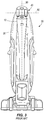
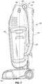
- FIG. 4 illustrates a vacuum cleaner 100 with an elongate handle 110.
- the vacuum cleaner 100 includes a suction nozzle 120, a cleaner housing or body 130 connected to the suction nozzle 120, a suction generator (not shown) in the cleaner housing 130, and a dirt collection vessel (not shown) in the cleaner housing 130.
- the handle 110 is coupled to the cleaner housing 130 at a pivot or hinge joint 140.
- the cleaner housing 130 defines a central longitudinal axis or centerline 150.
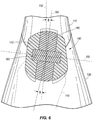
- the pivot joint 140 is configured to rotate the handle 110 about a pivot axis 160 that is non-perpendicular to the longitudinal axis 150.
- the handle 110 extends non-perpendicular to the pivot axis 160.
- the handle 110 is offset from an orientation 164 perpendicular to the pivot axis 160 at an acute angle ⁇ . As such, when the handle 110 is folded downwardly, the handle 110 is rotated substantially conically about the pivot axis 160.
- the pivot axis 160 is offset from an orientation perpendicular to the longitudinal axis 150 by approximately 5° to approximately 7°. In other embodiments, however, the pivot axis 160 may extend at other angles that are non-perpendicular to the longitudinal axis 150.
- the handle 110 when the handle 110 is rotated or folded downwardly for storing or shipping, the handle 110 moves to a position adjacent to and offset from the cleaner housing 130 of the vacuum cleaner 100.
- the handle 110 does not substantially protrude from the outer profile or contour of the cleaner housing 130 when the handle 110 is rotated downwardly.
- the vacuum cleaner 100 can be shipped or stored with the handle 110 in the folded position in a compact package without substantially increasing the footprint of the product compared to prior art configurations.
- the pivot joint 140 includes a female member 170 coupled to the cleaner housing 130 and a male member 180 coupled to the handle 110.
- the female member 170 can be coupled to the handle 110 and the male member 180 can be coupled to the cleaner housing 130.
- the male member 180 is positioned proximate the female member 170, and a pin 190 is insertable through the female and male members 170, 180 to couple the cleaner housing 130 and the handle 110 together.
- the female and male members 170, 180 are so dimensioned as to give a smooth substantially bulbous appearance when the pin 190 is inserted through the female and male members 170, 180.
- the handle 110 may include one or more male members 180, one or more female members 170, or a combination thereof.
- the cleaner housing 130 may also include one or more female members 170, one or more male members 180, or a combination thereof.
- the pivot joint 140 thus suitably includes one or more female and male members 170, 180.
- FIGS. 4-6 illustrate the female and male members 170, 180 as integrally formed with the cleaner housing 130 and handle 110, respectively, in other embodiments the female and male members 170, 180 may be separately formed and attached to a respective one of the cleaner housing 130 and handle 110 via glue or fasteners.
- the vacuum cleaner 100 includes a locking unit 200, which includes a detent 204 and a corresponding catch mechanism 208 (not shown in FIGS. 4-7 ; see, e.g., FIG. 11 ) between the cleaner housing 130 and the handle 110, and a release member 210 connected to the detent 204.
- the locking unit 200 is configured to releasably lock the handle 110 solely in a position substantially parallel to the longitudinal axis 150, i.e., the operating position.
- the release member 210 may be spring-loaded or biased by any other suitable mechanisms.
- the detent is selectively movable between a locked position where the detent 204 contacts the corresponding catch mechanism 208, and an unlocked position where the detent 204 is released out of the locking position.
- the detent 204 contacts the catch mechanisms 208 and locks the handle 110 so that the handle 110 fixedly extends upwardly and away from the cleaner housing 130.
- the detent 204 is released out of the locking position, thereby enabling the handle 110 to rotate or fold downwardly toward the storage position.
- the surface cleaning device 100 is a vacuum cleaner adapted to clean a variety of surfaces, such as carpets, hardwood floors, tiles, or the like. More specifically, the illustrated surface cleaning device 100 is an upright wet vacuum cleaner capable of drawing in air and dirt such as liquid and debris. In alternative embodiments, the surface cleaning device 100 may not be a wet vacuum cleaner. Rather, the surface cleaning device 100 may be a dry vacuum cleaner capable of drawing in air and dirt such as dry debris. Alternatively, the surface cleaning device 100 may be an extractor capable of both dispensing liquid and drawing in air and dirt such as liquid and debris. In yet other embodiments, the surface cleaning device 100 may be a steam cleaner that dispenses liquid or steam but does not include a suction source.
- the surface cleaning device 100 may be a stick vacuum that does not include the brush rolls of other traditional upright cleaners.
- surface cleaning device 100 may be a sweeper that includes a handle and a pivoting base that supports a wet or dry cloth that is positioned below the base. These sweepers do not dispense liquid and do not include a suction source.
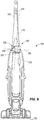
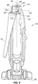
- FIGS. 8-11 illustrate the vacuum cleaner 100 including a pivot joint 140 according to another embodiment of the invention.
- the pivot joint 140 in this embodiment is configured to rotate the handle 110 about the pivot axis 160, and also to translate the handle 110 along the pivot axis 160.
- the pivot axis 160 is non-perpendicular to the longitudinal axis 150 so as to store or stow the handle 110 at an orientation offset from the longitudinal axis 150.
- the pivot axis 160 can be perpendicular to the longitudinal axis 150.
- the handle 110 can be stored or stowed at a position that is linearly, but not angularly, offset from the longitudinal axis 150.
- the pivot joint 140 includes a female member 220 coupled to the handle 110 and a male member 230 coupled to the cleaner housing 130.
- the male member 230 is received into the female member 220 to couple the cleaner housing 130 and the handle 110 together.
- the male member 230 includes a projection or thread 240
- the female member 220 includes a groove 250 that corresponds to the projection 240.
- the projection 240 extends helically about the pivot axis 160. The projection 240 and the groove cooperate together to translate the handle 110 along the pivot axis 160.
- the handle 110 when viewed from the rear in a direction substantially perpendicular to the longitudinal axis 150, the handle 110 is translated generally from right to left along the pivot axis 160 as the handle 110 is rotated from the operating position (see FIGS. 8 and 10 ) to the storage position (see FIGS. 9 and 11 ).
- the male member 230 may include the groove 250 and the female member 220 may include the projection 240.
- the female member 220 may be coupled to the cleaner housing 130 and the male member 230 may be coupled to the handle 110.
Landscapes
- Engineering & Computer Science (AREA)
- Mechanical Engineering (AREA)
- Electric Vacuum Cleaner (AREA)
- Cleaning By Liquid Or Steam (AREA)
Claims (7)
- Dispositif de nettoyage de surface (100) comprenant :une base ;un boîtier de nettoyage (130) couplé de manière pivotante à la base, le boîtier de nettoyage (130) définissant un axe longitudinal central (150) ;un plan défini par l'axe longitudinal central (150) et la direction en avant/en arrière du boîtier de nettoyage (130) ; etune poignée (110) couplée au boîtier de nettoyage (130) au niveau d'une articulation pivotante (140) de telle sorte que la poignée (110) peut être déplacée par rapport au boîtier de nettoyage (130) d'une position de fonctionnement vers le bas à une position de rangement,dans lequel la poignée (110) est sensiblement centrée sur l'axe longitudinal central (150) quand la poignée (110) est en position de fonctionnement, etcaractérisé en ce que, à mesure que la poignée (110) se déplace de la position de fonctionnement à la position de rangement, l'articulation pivotante (140) est configurée pour ranger de manière rotative la poignée (110) à une position décalée par rapport au plan.
- Dispositif de nettoyage de surface (100) selon la revendication 1, dans lequel la poignée (110) pivote par rapport au boîtier de nettoyage (130) autour d'un axe de pivotement (160) défini par l'articulation pivotante (140).
- Dispositif de nettoyage de surface (100) selon la revendication 2, dans lequel l'axe de pivotement (160) n'est pas perpendiculaire à l'axe longitudinal central (150).
- Dispositif de nettoyage de surface (100) selon la revendication 2, dans lequel la poignée (110) translate dans une direction le long de l'axe de pivotement (160) à mesure que la poignée (110) se déplace de la position de fonctionnement à la position de rangement.
- Dispositif de nettoyage de surface (100) selon la revendication 4, dans lequel la poignée (110) est sensiblement parallèle à l'axe longitudinal central (150) quand la poignée (110) est en position de rangement.
- Dispositif de nettoyage de surface (100) selon la revendication 4, dans lequel l'axe de pivotement (160) n'est pas perpendiculaire à l'axe longitudinal central (150).
- Dispositif de nettoyage de surface (100) selon la revendication 1, comprenant en outre un mécanisme de verrouillage (200) pour verrouiller la poignée (110) de manière sélective en position de fonctionnement.
Priority Applications (1)
| Application Number | Priority Date | Filing Date | Title |
|---|---|---|---|
| EP16182253.1A EP3141173B1 (fr) | 2013-11-15 | 2013-11-15 | Poignee pivotante pour un dispositif de nettoyage de surface |
Applications Claiming Priority (2)
| Application Number | Priority Date | Filing Date | Title |
|---|---|---|---|
| EP16182253.1A EP3141173B1 (fr) | 2013-11-15 | 2013-11-15 | Poignee pivotante pour un dispositif de nettoyage de surface |
| EP13193051.3A EP2873358B1 (fr) | 2013-11-15 | 2013-11-15 | Poignée pivotante pour un dispositif de nettoyage de surface |
Related Parent Applications (2)
| Application Number | Title | Priority Date | Filing Date |
|---|---|---|---|
| EP13193051.3A Division-Into EP2873358B1 (fr) | 2013-11-15 | 2013-11-15 | Poignée pivotante pour un dispositif de nettoyage de surface |
| EP13193051.3A Division EP2873358B1 (fr) | 2013-11-15 | 2013-11-15 | Poignée pivotante pour un dispositif de nettoyage de surface |
Publications (3)
| Publication Number | Publication Date |
|---|---|
| EP3141173A2 EP3141173A2 (fr) | 2017-03-15 |
| EP3141173A3 EP3141173A3 (fr) | 2017-04-12 |
| EP3141173B1 true EP3141173B1 (fr) | 2020-01-15 |
Family
ID=49639719
Family Applications (2)
| Application Number | Title | Priority Date | Filing Date |
|---|---|---|---|
| EP16182253.1A Active EP3141173B1 (fr) | 2013-11-15 | 2013-11-15 | Poignee pivotante pour un dispositif de nettoyage de surface |
| EP13193051.3A Not-in-force EP2873358B1 (fr) | 2013-11-15 | 2013-11-15 | Poignée pivotante pour un dispositif de nettoyage de surface |
Family Applications After (1)
| Application Number | Title | Priority Date | Filing Date |
|---|---|---|---|
| EP13193051.3A Not-in-force EP2873358B1 (fr) | 2013-11-15 | 2013-11-15 | Poignée pivotante pour un dispositif de nettoyage de surface |
Country Status (1)
| Country | Link |
|---|---|
| EP (2) | EP3141173B1 (fr) |
Families Citing this family (1)
| Publication number | Priority date | Publication date | Assignee | Title |
|---|---|---|---|---|
| WO2018231831A1 (fr) * | 2017-06-12 | 2018-12-20 | Sharkninja Operating Llc | Dispositif de nettoyage de surface à configuration de stockage compacte |
Family Cites Families (16)
| Publication number | Priority date | Publication date | Assignee | Title |
|---|---|---|---|---|
| GB729807A (en) * | 1952-06-02 | 1955-05-11 | Hoover Ltd | Improvements relating to suction cleaners |
| GB771323A (en) * | 1954-07-28 | 1957-03-27 | Neptric Ltd | Improvements in vacuum cleaners |
| US3758914A (en) * | 1971-10-06 | 1973-09-18 | Whirlpool Co | Vacuum cleaner with movable handle structure |
| DE3435878A1 (de) * | 1984-09-29 | 1986-04-10 | Licentia Patent-Verwaltungs-Gmbh, 6000 Frankfurt | Staubsauger mit einer schwenkbaren handhabe |
| JPS6432829A (en) * | 1987-07-29 | 1989-02-02 | Tokyo Electric Co Ltd | Electric cleaner |
| JP3460328B2 (ja) * | 1994-09-20 | 2003-10-27 | 松下電器産業株式会社 | 縦型電気掃除機 |
| GB2318279A (en) * | 1996-10-16 | 1998-04-22 | Electrolux Ltd | Suction cleaner handle |
| US6101672A (en) * | 1999-07-27 | 2000-08-15 | Fantom Technologies Inc. | Rotatable handle for a vacuum cleaner |
| JP2001218717A (ja) * | 2000-02-08 | 2001-08-14 | Hitachi Ltd | 電気掃除機 |
| JP2001340278A (ja) * | 2000-06-02 | 2001-12-11 | Hitachi Ltd | 電気掃除機 |
| US6768073B1 (en) * | 2003-07-03 | 2004-07-27 | The Hoover Company | Pivoting handle and control arrangement for a floor care appliance |
| KR20050058163A (ko) * | 2003-12-11 | 2005-06-16 | 엘지전자 주식회사 | 업라이트형 진공청소기 |
| GB2433022A (en) * | 2005-12-08 | 2007-06-13 | Hoover Ltd | Vacuum cleaner with folding handle |
| US9675227B2 (en) * | 2006-07-25 | 2017-06-13 | Andrew John Potoroka | Vacuum cleaner with swivel and swing handle |
| US7584522B1 (en) * | 2007-02-14 | 2009-09-08 | F.V.S., Inc. | Vertical cyclonic vacuum assembly |
| CN201271204Y (zh) * | 2008-09-23 | 2009-07-15 | 美的集团有限公司 | 一种立式吸尘器 |
-
2013
- 2013-11-15 EP EP16182253.1A patent/EP3141173B1/fr active Active
- 2013-11-15 EP EP13193051.3A patent/EP2873358B1/fr not_active Not-in-force
Non-Patent Citations (1)
| Title |
|---|
| None * |
Also Published As
| Publication number | Publication date |
|---|---|
| EP2873358A1 (fr) | 2015-05-20 |
| EP2873358B1 (fr) | 2016-09-28 |
| EP3141173A2 (fr) | 2017-03-15 |
| EP3141173A3 (fr) | 2017-04-12 |
Similar Documents
| Publication | Publication Date | Title |
|---|---|---|
| US9480378B2 (en) | Pivoting handle for a surface cleaning device | |
| CN104644060B (zh) | 用于表面清洁装置的枢转手柄 | |
| US12539006B2 (en) | Vacuum cleaning device with foldable wand to provide storage configuration | |
| CN100593387C (zh) | 真空吸尘器 | |
| JP7625728B2 (ja) | 真空クリーナー用のワンド | |
| KR100429113B1 (ko) | 전기 진공 청소기 | |
| US7356874B2 (en) | Vacuum cleaner | |
| CN109715018B (zh) | 用于真空吸尘器的清洁头 | |
| KR20210057810A (ko) | 하나 이상의 스태빌라이저를 갖는 표면 처리 장치용 청소 헤드 및 이를 갖는 표면 처리 장치 | |
| JP4692590B2 (ja) | 掃除機用取っ手組立体 | |
| US20080263814A1 (en) | Upright Vacuum Cleaner | |
| PL188743B1 (pl) | Rura węża ssącego odkurzacza | |
| KR20220012727A (ko) | 진공청소기 | |
| US8914937B2 (en) | Hinge assembly for steam cleaner | |
| EP3141173B1 (fr) | Poignee pivotante pour un dispositif de nettoyage de surface | |
| US7386917B2 (en) | Vacuum cleaner with quick release wand | |
| JP2010022855A (ja) | 電気掃除機用吸込具 | |
| JP4228227B2 (ja) | 電気掃除機 | |
| CN116158686A (zh) | 配有能在缩回位置和展开位置之间移动的吸头的吸尘器 | |
| KR20240085006A (ko) | 청소기 | |
| CN116158687A (zh) | 配有副吸头的吸尘器 | |
| JP2006325979A (ja) | 電気掃除機用吸込具 | |
| CN120203438A (zh) | 罐式吸尘器的附件 | |
| CN101843462A (zh) | 装备具有弯折防护功能的闩销组件的地面护理装置 | |
| GB2413063A (en) | Vacuum cleaner having suction handle |
Legal Events
| Date | Code | Title | Description |
|---|---|---|---|
| PUAI | Public reference made under article 153(3) epc to a published international application that has entered the european phase |
Free format text: ORIGINAL CODE: 0009012 |
|
| STAA | Information on the status of an ep patent application or granted ep patent |
Free format text: STATUS: THE APPLICATION HAS BEEN PUBLISHED |
|
| PUAL | Search report despatched |
Free format text: ORIGINAL CODE: 0009013 |
|
| AC | Divisional application: reference to earlier application |
Ref document number: 2873358 Country of ref document: EP Kind code of ref document: P |
|
| AK | Designated contracting states |
Kind code of ref document: A2 Designated state(s): AL AT BE BG CH CY CZ DE DK EE ES FI FR GB GR HR HU IE IS IT LI LT LU LV MC MK MT NL NO PL PT RO RS SE SI SK SM TR |
|
| AK | Designated contracting states |
Kind code of ref document: A3 Designated state(s): AL AT BE BG CH CY CZ DE DK EE ES FI FR GB GR HR HU IE IS IT LI LT LU LV MC MK MT NL NO PL PT RO RS SE SI SK SM TR |
|
| RIC1 | Information provided on ipc code assigned before grant |
Ipc: A47L 9/00 20060101ALI20170306BHEP Ipc: A47L 9/32 20060101AFI20170306BHEP |
|
| STAA | Information on the status of an ep patent application or granted ep patent |
Free format text: STATUS: REQUEST FOR EXAMINATION WAS MADE |
|
| 17P | Request for examination filed |
Effective date: 20171011 |
|
| RBV | Designated contracting states (corrected) |
Designated state(s): AL AT BE BG CH CY CZ DE DK EE ES FI FR GB GR HR HU IE IS IT LI LT LU LV MC MK MT NL NO PL PT RO RS SE SI SK SM TR |
|
| STAA | Information on the status of an ep patent application or granted ep patent |
Free format text: STATUS: EXAMINATION IS IN PROGRESS |
|
| 17Q | First examination report despatched |
Effective date: 20181126 |
|
| GRAP | Despatch of communication of intention to grant a patent |
Free format text: ORIGINAL CODE: EPIDOSNIGR1 |
|
| STAA | Information on the status of an ep patent application or granted ep patent |
Free format text: STATUS: GRANT OF PATENT IS INTENDED |
|
| INTG | Intention to grant announced |
Effective date: 20190805 |
|
| GRAS | Grant fee paid |
Free format text: ORIGINAL CODE: EPIDOSNIGR3 |
|
| GRAA | (expected) grant |
Free format text: ORIGINAL CODE: 0009210 |
|
| STAA | Information on the status of an ep patent application or granted ep patent |
Free format text: STATUS: THE PATENT HAS BEEN GRANTED |
|
| AC | Divisional application: reference to earlier application |
Ref document number: 2873358 Country of ref document: EP Kind code of ref document: P |
|
| AK | Designated contracting states |
Kind code of ref document: B1 Designated state(s): AL AT BE BG CH CY CZ DE DK EE ES FI FR GB GR HR HU IE IS IT LI LT LU LV MC MK MT NL NO PL PT RO RS SE SI SK SM TR |
|
| REG | Reference to a national code |
Ref country code: CH Ref legal event code: EP Ref country code: GB Ref legal event code: FG4D |
|
| REG | Reference to a national code |
Ref country code: IE Ref legal event code: FG4D |
|
| REG | Reference to a national code |
Ref country code: DE Ref legal event code: R096 Ref document number: 602013065230 Country of ref document: DE |
|
| REG | Reference to a national code |
Ref country code: AT Ref legal event code: REF Ref document number: 1224422 Country of ref document: AT Kind code of ref document: T Effective date: 20200215 |
|
| REG | Reference to a national code |
Ref country code: NL Ref legal event code: MP Effective date: 20200115 |
|
| REG | Reference to a national code |
Ref country code: LT Ref legal event code: MG4D |
|
| PG25 | Lapsed in a contracting state [announced via postgrant information from national office to epo] |
Ref country code: RS Free format text: LAPSE BECAUSE OF FAILURE TO SUBMIT A TRANSLATION OF THE DESCRIPTION OR TO PAY THE FEE WITHIN THE PRESCRIBED TIME-LIMIT Effective date: 20200115 Ref country code: NL Free format text: LAPSE BECAUSE OF FAILURE TO SUBMIT A TRANSLATION OF THE DESCRIPTION OR TO PAY THE FEE WITHIN THE PRESCRIBED TIME-LIMIT Effective date: 20200115 Ref country code: PT Free format text: LAPSE BECAUSE OF FAILURE TO SUBMIT A TRANSLATION OF THE DESCRIPTION OR TO PAY THE FEE WITHIN THE PRESCRIBED TIME-LIMIT Effective date: 20200607 Ref country code: FI Free format text: LAPSE BECAUSE OF FAILURE TO SUBMIT A TRANSLATION OF THE DESCRIPTION OR TO PAY THE FEE WITHIN THE PRESCRIBED TIME-LIMIT Effective date: 20200115 Ref country code: NO Free format text: LAPSE BECAUSE OF FAILURE TO SUBMIT A TRANSLATION OF THE DESCRIPTION OR TO PAY THE FEE WITHIN THE PRESCRIBED TIME-LIMIT Effective date: 20200415 |
|
| PG25 | Lapsed in a contracting state [announced via postgrant information from national office to epo] |
Ref country code: HR Free format text: LAPSE BECAUSE OF FAILURE TO SUBMIT A TRANSLATION OF THE DESCRIPTION OR TO PAY THE FEE WITHIN THE PRESCRIBED TIME-LIMIT Effective date: 20200115 Ref country code: BG Free format text: LAPSE BECAUSE OF FAILURE TO SUBMIT A TRANSLATION OF THE DESCRIPTION OR TO PAY THE FEE WITHIN THE PRESCRIBED TIME-LIMIT Effective date: 20200415 Ref country code: GR Free format text: LAPSE BECAUSE OF FAILURE TO SUBMIT A TRANSLATION OF THE DESCRIPTION OR TO PAY THE FEE WITHIN THE PRESCRIBED TIME-LIMIT Effective date: 20200416 Ref country code: IS Free format text: LAPSE BECAUSE OF FAILURE TO SUBMIT A TRANSLATION OF THE DESCRIPTION OR TO PAY THE FEE WITHIN THE PRESCRIBED TIME-LIMIT Effective date: 20200515 Ref country code: LV Free format text: LAPSE BECAUSE OF FAILURE TO SUBMIT A TRANSLATION OF THE DESCRIPTION OR TO PAY THE FEE WITHIN THE PRESCRIBED TIME-LIMIT Effective date: 20200115 Ref country code: SE Free format text: LAPSE BECAUSE OF FAILURE TO SUBMIT A TRANSLATION OF THE DESCRIPTION OR TO PAY THE FEE WITHIN THE PRESCRIBED TIME-LIMIT Effective date: 20200115 |
|
| REG | Reference to a national code |
Ref country code: DE Ref legal event code: R097 Ref document number: 602013065230 Country of ref document: DE |
|
| PG25 | Lapsed in a contracting state [announced via postgrant information from national office to epo] |
Ref country code: CZ Free format text: LAPSE BECAUSE OF FAILURE TO SUBMIT A TRANSLATION OF THE DESCRIPTION OR TO PAY THE FEE WITHIN THE PRESCRIBED TIME-LIMIT Effective date: 20200115 Ref country code: SK Free format text: LAPSE BECAUSE OF FAILURE TO SUBMIT A TRANSLATION OF THE DESCRIPTION OR TO PAY THE FEE WITHIN THE PRESCRIBED TIME-LIMIT Effective date: 20200115 Ref country code: RO Free format text: LAPSE BECAUSE OF FAILURE TO SUBMIT A TRANSLATION OF THE DESCRIPTION OR TO PAY THE FEE WITHIN THE PRESCRIBED TIME-LIMIT Effective date: 20200115 Ref country code: EE Free format text: LAPSE BECAUSE OF FAILURE TO SUBMIT A TRANSLATION OF THE DESCRIPTION OR TO PAY THE FEE WITHIN THE PRESCRIBED TIME-LIMIT Effective date: 20200115 Ref country code: SM Free format text: LAPSE BECAUSE OF FAILURE TO SUBMIT A TRANSLATION OF THE DESCRIPTION OR TO PAY THE FEE WITHIN THE PRESCRIBED TIME-LIMIT Effective date: 20200115 Ref country code: DK Free format text: LAPSE BECAUSE OF FAILURE TO SUBMIT A TRANSLATION OF THE DESCRIPTION OR TO PAY THE FEE WITHIN THE PRESCRIBED TIME-LIMIT Effective date: 20200115 Ref country code: LT Free format text: LAPSE BECAUSE OF FAILURE TO SUBMIT A TRANSLATION OF THE DESCRIPTION OR TO PAY THE FEE WITHIN THE PRESCRIBED TIME-LIMIT Effective date: 20200115 Ref country code: ES Free format text: LAPSE BECAUSE OF FAILURE TO SUBMIT A TRANSLATION OF THE DESCRIPTION OR TO PAY THE FEE WITHIN THE PRESCRIBED TIME-LIMIT Effective date: 20200115 |
|
| REG | Reference to a national code |
Ref country code: AT Ref legal event code: MK05 Ref document number: 1224422 Country of ref document: AT Kind code of ref document: T Effective date: 20200115 |
|
| PLBE | No opposition filed within time limit |
Free format text: ORIGINAL CODE: 0009261 |
|
| STAA | Information on the status of an ep patent application or granted ep patent |
Free format text: STATUS: NO OPPOSITION FILED WITHIN TIME LIMIT |
|
| 26N | No opposition filed |
Effective date: 20201016 |
|
| PG25 | Lapsed in a contracting state [announced via postgrant information from national office to epo] |
Ref country code: IT Free format text: LAPSE BECAUSE OF FAILURE TO SUBMIT A TRANSLATION OF THE DESCRIPTION OR TO PAY THE FEE WITHIN THE PRESCRIBED TIME-LIMIT Effective date: 20200115 Ref country code: AT Free format text: LAPSE BECAUSE OF FAILURE TO SUBMIT A TRANSLATION OF THE DESCRIPTION OR TO PAY THE FEE WITHIN THE PRESCRIBED TIME-LIMIT Effective date: 20200115 |
|
| PG25 | Lapsed in a contracting state [announced via postgrant information from national office to epo] |
Ref country code: PL Free format text: LAPSE BECAUSE OF FAILURE TO SUBMIT A TRANSLATION OF THE DESCRIPTION OR TO PAY THE FEE WITHIN THE PRESCRIBED TIME-LIMIT Effective date: 20200115 Ref country code: SI Free format text: LAPSE BECAUSE OF FAILURE TO SUBMIT A TRANSLATION OF THE DESCRIPTION OR TO PAY THE FEE WITHIN THE PRESCRIBED TIME-LIMIT Effective date: 20200115 |
|
| PG25 | Lapsed in a contracting state [announced via postgrant information from national office to epo] |
Ref country code: MC Free format text: LAPSE BECAUSE OF FAILURE TO SUBMIT A TRANSLATION OF THE DESCRIPTION OR TO PAY THE FEE WITHIN THE PRESCRIBED TIME-LIMIT Effective date: 20200115 |
|
| REG | Reference to a national code |
Ref country code: CH Ref legal event code: PL |
|
| PG25 | Lapsed in a contracting state [announced via postgrant information from national office to epo] |
Ref country code: LU Free format text: LAPSE BECAUSE OF NON-PAYMENT OF DUE FEES Effective date: 20201115 |
|
| REG | Reference to a national code |
Ref country code: BE Ref legal event code: MM Effective date: 20201130 |
|
| PG25 | Lapsed in a contracting state [announced via postgrant information from national office to epo] |
Ref country code: LI Free format text: LAPSE BECAUSE OF NON-PAYMENT OF DUE FEES Effective date: 20201130 Ref country code: CH Free format text: LAPSE BECAUSE OF NON-PAYMENT OF DUE FEES Effective date: 20201130 |
|
| PG25 | Lapsed in a contracting state [announced via postgrant information from national office to epo] |
Ref country code: IE Free format text: LAPSE BECAUSE OF NON-PAYMENT OF DUE FEES Effective date: 20201115 |
|
| PG25 | Lapsed in a contracting state [announced via postgrant information from national office to epo] |
Ref country code: TR Free format text: LAPSE BECAUSE OF FAILURE TO SUBMIT A TRANSLATION OF THE DESCRIPTION OR TO PAY THE FEE WITHIN THE PRESCRIBED TIME-LIMIT Effective date: 20200115 Ref country code: MT Free format text: LAPSE BECAUSE OF FAILURE TO SUBMIT A TRANSLATION OF THE DESCRIPTION OR TO PAY THE FEE WITHIN THE PRESCRIBED TIME-LIMIT Effective date: 20200115 Ref country code: CY Free format text: LAPSE BECAUSE OF FAILURE TO SUBMIT A TRANSLATION OF THE DESCRIPTION OR TO PAY THE FEE WITHIN THE PRESCRIBED TIME-LIMIT Effective date: 20200115 |
|
| PG25 | Lapsed in a contracting state [announced via postgrant information from national office to epo] |
Ref country code: MK Free format text: LAPSE BECAUSE OF FAILURE TO SUBMIT A TRANSLATION OF THE DESCRIPTION OR TO PAY THE FEE WITHIN THE PRESCRIBED TIME-LIMIT Effective date: 20200115 Ref country code: AL Free format text: LAPSE BECAUSE OF FAILURE TO SUBMIT A TRANSLATION OF THE DESCRIPTION OR TO PAY THE FEE WITHIN THE PRESCRIBED TIME-LIMIT Effective date: 20200115 |
|
| PG25 | Lapsed in a contracting state [announced via postgrant information from national office to epo] |
Ref country code: BE Free format text: LAPSE BECAUSE OF NON-PAYMENT OF DUE FEES Effective date: 20201130 |
|
| PGFP | Annual fee paid to national office [announced via postgrant information from national office to epo] |
Ref country code: GB Payment date: 20221128 Year of fee payment: 10 Ref country code: FR Payment date: 20221123 Year of fee payment: 10 Ref country code: DE Payment date: 20221125 Year of fee payment: 10 |
|
| REG | Reference to a national code |
Ref country code: DE Ref legal event code: R119 Ref document number: 602013065230 Country of ref document: DE |
|
| GBPC | Gb: european patent ceased through non-payment of renewal fee |
Effective date: 20231115 |
|
| PG25 | Lapsed in a contracting state [announced via postgrant information from national office to epo] |
Ref country code: DE Free format text: LAPSE BECAUSE OF NON-PAYMENT OF DUE FEES Effective date: 20240601 |
|
| PG25 | Lapsed in a contracting state [announced via postgrant information from national office to epo] |
Ref country code: GB Free format text: LAPSE BECAUSE OF NON-PAYMENT OF DUE FEES Effective date: 20231115 |
|
| PG25 | Lapsed in a contracting state [announced via postgrant information from national office to epo] |
Ref country code: FR Free format text: LAPSE BECAUSE OF NON-PAYMENT OF DUE FEES Effective date: 20231130 |
|
| PG25 | Lapsed in a contracting state [announced via postgrant information from national office to epo] |
Ref country code: GB Free format text: LAPSE BECAUSE OF NON-PAYMENT OF DUE FEES Effective date: 20231115 Ref country code: FR Free format text: LAPSE BECAUSE OF NON-PAYMENT OF DUE FEES Effective date: 20231130 Ref country code: DE Free format text: LAPSE BECAUSE OF NON-PAYMENT OF DUE FEES Effective date: 20240601 |