EP3141175B1 - Dispositif de serpillière avec vessie pour stockage de fluide - Google Patents
Dispositif de serpillière avec vessie pour stockage de fluide Download PDFInfo
- Publication number
- EP3141175B1 EP3141175B1 EP16182650.8A EP16182650A EP3141175B1 EP 3141175 B1 EP3141175 B1 EP 3141175B1 EP 16182650 A EP16182650 A EP 16182650A EP 3141175 B1 EP3141175 B1 EP 3141175B1
- Authority
- EP
- European Patent Office
- Prior art keywords
- reservoir
- fluid
- bladder
- mopping
- mopping device
- Prior art date
- Legal status (The legal status is an assumption and is not a legal conclusion. Google has not performed a legal analysis and makes no representation as to the accuracy of the status listed.)
- Active
Links
Images






Classifications
-
- A—HUMAN NECESSITIES
- A47—FURNITURE; DOMESTIC ARTICLES OR APPLIANCES; COFFEE MILLS; SPICE MILLS; SUCTION CLEANERS IN GENERAL
- A47L—DOMESTIC WASHING OR CLEANING; SUCTION CLEANERS IN GENERAL
- A47L13/00—Implements for cleaning floors, carpets, furniture, walls, or wall coverings
- A47L13/10—Scrubbing; Scouring; Cleaning; Polishing
- A47L13/20—Mops
- A47L13/22—Mops with liquid-feeding devices
Definitions
- the present invention relates generally to a mopping device. More particularly, the present invention relates to a mopping device that releases fluid from a fluid reservoir onto a surface to be mopped.
- Mopping systems incorporating fluid dispensing devices often have a fluid reservoir on the handle or stick of the mop and some means to dispense cleaning or finishing fluid (typically a liquid) onto a floor surface or the mop, in a manner controlled by the user. These mopping systems may hold the fluid inside the handle or in a tank attached to the handle.
- cleaning or finishing fluid typically a liquid
- a rigid reservoir can require a vent, which can allow leakage of the cleaning or finishing fluid. Because the reservoir is rigid, its inner volume typically will be filled by a combination of air and cleaning or finishing fluid. Consequently, refilling the reservoir requires a vent that will allow the air to leave the reservoir as it is replaced by cleaning or finishing fluid. The vent also is needed to allow air to return to the reservoir as cleaning or finishing fluid is dispensed. The vent can allow fluid to leak from the reservoir. For example, a leak can occur when the mopping system is laid down or inverted.
- Some existing mopping systems have inconvenient ergonomics.
- the mechanism with which the user releases the fluid is often awkward to use, or is designed for use in a single orientation.
- Some existing mopping systems can be difficult to fill.
- the reservoir that holds the fluid may be located in an undesirable location. Additionally, the openings can be too small to accommodate the fluids, thereby raising the potential for spillage. In some instances, the fluid-fill level can be difficult to determine, which can lead to under-filling and thus inefficient usage, or over-filling and spillage.
- WO2004/064590 discloses a mop having a mop handle with a mop head at one end and a handle grip at the other end. Intermediate the mop head and the handle grip is a container holder and a container. The container is held in the container holder with the dispensing end of the container facing downward to the floor. Depending on the orientation of the container holder on the mop handle the liquid in the container can be dispensed "fore" or "aft" of the mop head. Further, the container can be removed from the mop handle and the liquid dispensed onto the floor. The liquid is dispensed from the container by squeezing the container.
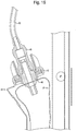
- FIGS. 1 to 15 show a mopping device 10 according to an exemplary embodiment.
- FIG. 12 shows the mopping device 10 connected to a refill reservoir, to form a mopping system according to an exemplary embodiment.
- the preferred mopping device 10 includes a mopping portion, a fluid release device for releasing fluid, a handle, and a reservoir for storing fluid that is intended to be released by the fluid release device.
- the fluid release device 16 releases fluid for mopping.
- the fluid can be released onto the surface to be mopped.
- the fluid release device 16 can be configured to allow the user to dispense liquid onto the surface in front of or behind the mopping portion 12, as required. Less preferably (and not shown), the fluid can be released onto the mopping material itself.
- Fluid release device 16 preferably includes a user interface in the form of a trigger button 26 located on a hand grip 28 positioned at the top of the handle 18. Pressing the trigger button 26 causes fluid to be dispensed from a sprayer 38, preferably in a variable and controlled manner.
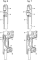
- the upward pulling of cable 32 opens a dispensing valve 34 (from the position shown in FIG. 7 to the position shown in FIG. 6 ).
- the dispensing valve 34 can be constructed, as shown for example in FIGS 6 and 7 , to include a plunger 36 having o-rings that seat in a portion of a fluid passage to prevent fluid flow and that can be pulled from the seated position to permit such flow.
- the upward pulling of cable 32 lifts the plunger 36 in the valve 34, which allows fluid to flow from a tube 27 extending from the reservoir 20 and to a dispensing tube 40.
- the fluid from the dispensing tube 40 is preferably sprayed by a conventional sprayer 38 disposed at the end of the tube 40.
- the sprayer 38 can be selected to provide a desired spray pattern.
- the sprayer 38 preferably is disposed on the lower region of handle 18 at any point beyond the dispensing valve 34, thus allowing the sprayer 38 to be changed without emptying bladder 21.
- the mopping device 10 can be positioned by the user in a variety of orientations. These orientations will change the location at which fluid is sprayed.
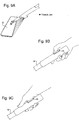
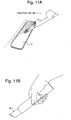
- the location of the trigger button 26 allows it to be pressed with the users fingers, thumb, or palm depending on user preference and the orientation of mopping device 10.
- trigger button 26 can be pressed with a finger or fingers allowing liquid to be dispensed behind mopping portion 12.
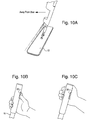
- FIGS. 9A to 9C where handle 18 of the mopping device 10 is shown in a lower position, the trigger button 26 can be pressed with the thumb or palm, again allowing liquid to be dispensed behind mopping portion 12.
- the handle 18 enables a user to control mopping portion 12.
- the handle 18 can be generally conventional mop handle or stick.
- Preferably the handle 18 is connected to the support 13 of the mopping portion 12 by a conventional hinge structure.
- the reservoir 20 stores, on the mopping device 10, the fluid to be dispensed.
- the reservoir 20 can include an expandable bladder 21 for storing fluid and a reservoir housing 23 that is connected to handle 18 and holds the bladder 21.
- the reservoir housing 23 preferably is located within a top 80% of the length of the handle 18 and, more preferably, within a top 30% of the length of the handle 18.
- bladder 21 can be a transparent and flexible material that is configured to hold a fluid. Conventional plastic materials could be used to form the bladder 21.
- the bladder 21 preferably has a volume when filled of about 15 to 30 ounccs, and more preferably, 21 ounces.
- the bladder 21 has an opening at its top, which allows fluid to be filled into the bladder 21, and has an opening at its bottom, which allows fluid to flow into the tube 27 for dispensing.
- the reservoir housing 23 can be a generally hollow structure made, for example, of conventional plastic material. As shown in FIG. 5 , reservoir housing 23 can be structurally rigid and form a container and a protective shield for bladder 21, e.g., to prevent puncturing of bladder 21 should the mopping device 10 be struck or dropped. Reservoir housing 23 also includes open area(s) or window(s) 24 which allow a user to observe the level of the liquid in the enclosed bladder 21. Window 24 can extend substantially the entire length of reservoir housing 23. The user is thereby allowed to see how much liquid remains in bladder 21 at all times and can therefore determine when the reservoir 20 requires filling. The window 24 also assists the user when filling bladder 21. The user can determine the fullness of the bladder 21 to prevent spillage during the fill process.
- the mopping device 10 is preferably part of a mopping system that includes a refill reservoir 80 that can be used to refill the reservoir 20.
- the refill reservoir 80 preferably is a plastic container 82 having a screw-top lid 83.
- the plastic container 82 preferably has a volume of about 1 to 4 gallons.
- a flexible hose 50 can be connected to the plastic container 82 to permit fluid to flow out of the plastic container 82.
- a connector 48 is preferably affixed to the end of flexible hose 50.
- the connector 48 is designed to mate with a fitting (described below) on the reservoir 20.
- the connector 48 preferably is configured to permit fluid to flow from the hose 50 into the reservoir 20 when the connector is mated to the fitting, and to prevent fluid flow from the hose 50 when the connector 48 is not connected to the fitting.
- the connector 48 can be, for example, part. no. NS4D17006, made by Colder Products.
- a preferred fitting 46 for the reservoir 20 is shown in FIGS. 13 to 15 .
- the fitting 46 can be disposed in a fill cap 42 that screws onto conventional threads on the reservoir housing 23.
- the fitting 46 has the capabilities of auto shut-off, limited spill, quick-connect or any combination thereof.
- the fitting 46 preferably provides a valve that permits fluid flow into the reservoir 20 during filling but does not permit fluid flow out of the reservoir.
- the fitting 46 can be, for example, part. no. NS4D42006, made by Colder Products.
- the connector 48 and the fitting 46 are configured to provide a dripless connection.
- the connector 48 of the refill reservoir 80 is connected to the fitting 46 of the reservoir 20. Fluid then flows from the refill reservoir 80 into the bladder 21 of the reservoir 20 under the force of gravity or, alternatively, under the force of additional pressure.
- the fill level of the bladder 21 can be monitored by looking through windows 24 on the reservoir housing 23.
- the connector 48 can be removed from the fitting 46, and the mopping device 10 is ready for use. Due to the configuration of the fitting 46, fluid will not flow back out through that fitting after the connector 48 is removed.
- the mopping device 10 can be easily and quickly refilled, which reduces the need to hold a large volume of liquid. This advantageously allows for a reduction in the size and weight of the reservoir 20, which provides a more user friendly device. With its slim form, the mopping device 10 is also easy to use in confined spaces and can have convenient ergonomics.
- Coupled means the joining of two components (electrical or mechanical) directly or indirectly to one another. Such joining may be stationary in nature or movable in nature. Such joining can be achieved with the two components (electrical and mechanical) and any additional intermediate members being integrally formed a s a single unitary body with one another or with the two components or the two components and any additional member being attached to one another. Such joining can be permanent in nature or alternatively may be removable or releasable in nature.
Landscapes
- Cleaning Implements For Floors, Carpets, Furniture, Walls, And The Like (AREA)
Claims (12)
- Dispositif de nettoyage de sol, comprenant :une partie de nettoyage de sol (12) ;un dispositif de libération de fluide (16) pour libérer un fluide sur une surface destinée à être nettoyée ;un manche (18) configuré pour être saisi par un utilisateur pour commander la partie de nettoyage de sol ;un réservoir (20) pour stocker un fluide, dans lequel le réservoir inclut une vessie aplatissable re-remplissable (21) ;un logement de réservoir (23) raccordé au manche et ayant une surface d'extrémité faisant face à la partie de nettoyage de sol, la vessie aplatissable (21) étant située à l'intérieur du logement de réservoir ; etun pulvérisateur (38) configuré pour distribuer un fluide en une pluralité de courants derrière ou devant la partie de nettoyage de sol, le pulvérisateur étant monté sur la surface d'extrémité du logement de réservoir de telle sorte que la distribution de fluide à partir du pulvérisateur se produise au niveau de la surface d'extrémité du logement de réservoir,dans lequel la vessie (21) a une première ouverture en haut de la vessie et une seconde ouverture en bas de la vessie, la première ouverture étant configurée pour permettre au fluide de remplir la vessie jusqu'à un état agrandi depuis un état aplati et la seconde ouverture étant configurée pour permettre au fluide de s'écouler dans le pulvérisateur de telle sorte que la vessie s'aplatisse pour retourner à l'état aplati lorsqu'elle est vidée de fluide.
- Dispositif de nettoyage de sol selon la revendication 1, dans lequel la vessie est sensiblement sans air, et optionnellement ou de préférence, dans lequel la vessie n'inclut pas d'évent.
- Dispositif de nettoyage de sol selon la revendication 1, comprenant en outre une valve de distribution (34) ouvrable dans une position de distribution dans laquelle un fluide provenant du réservoir est capable de s'écouler dans le pulvérisateur ; dans lequel le pulvérisateur est positionné en aval de la valve de distribution.
- Dispositif de nettoyage de sol selon la revendication 1, dans lequel la vessie n'inclut pas d'évent, autre que les premier et seconde ouvertures.
- Dispositif de nettoyage de sol selon une quelconque revendication précédente, dans lequel la vessie est configurée pour être remplie et vidée de fluide seulement en raison de la gravité.
- Dispositif de nettoyage de sol selon l'une quelconque des revendications 1 à 4, dans lequel la vessie est sensiblement sans air ; et optionnellement ou de préférence, dans lequel la vessie est configurée pour être remplie et vidée de fluide sous la force d'une pression supplémentaire.
- Dispositif de nettoyage de sol selon l'une quelconque des revendications précédentes, comprenant en outre :un bouchon de remplissage (42) configuré pour être vissé sur le logement de réservoir ; etun accessoire à raccordement rapide (46) disposé dans le bouchon de remplissage, dans lequel l'accessoire fournit une valve pour permettre un écoulement de fluide dans le réservoir pour remplir le réservoir et ne pas permettre d'écoulement de fluide hors du réservoir.
- Dispositif de nettoyage de sol selon la revendication 7, comprenant en outre un réservoir de re-remplissage (80) incluant un raccord de re-remplissage (48) pour mécaniquement s'attacher à l'accessoire à raccordement rapide pour permettre un écoulement de fluide depuis le réservoir de re-remplissage jusqu'au réservoir ; et optionnellement ou de préférence, dans lequel le réservoir de re-remplissage comprend une partie de réservoir principale et un tube (50) s'étendant depuis la partie de réservoir principale jusqu'au raccord de re-remplissage.
- Dispositif de nettoyage de sol selon la revendication 8, dans lequel le raccord de re-remplissage et l'accessoire à raccordement rapide sont configurés pour fournir un raccordement anti-goutte.
- Dispositif de nettoyage de sol selon la revendication 8 ou 9, configuré de telle sorte que le fluide s'écoule depuis le réservoir de re-remplissage dans le réservoir sous la force de gravité ; ou sous la force de pression supplémentaire.
- Dispositif de nettoyage de sol selon une quelconque revendication précédente, dans lequel le logement de réservoir est situé au sein des 80 % supérieurs du manche et, optionnellement ou de préférence, dans lequel le logement de réservoir est situé au sein des 30 % inférieurs du manche ; et optionnellement ou de préférence, dans lequel le logement de réservoir comprend une fenêtre (24) pour surveiller le niveau de fluide dans le réservoir.
- Dispositif de nettoyage de sol selon une quelconque revendication précédente, dans lequel la partie de nettoyage de sol inclut un patin microfibres (14).
Applications Claiming Priority (6)
| Application Number | Priority Date | Filing Date | Title |
|---|---|---|---|
| US85344606P | 2006-10-23 | 2006-10-23 | |
| US89535107P | 2007-03-16 | 2007-03-16 | |
| US94289107P | 2007-06-08 | 2007-06-08 | |
| US95211707P | 2007-07-26 | 2007-07-26 | |
| PCT/US2007/082240 WO2008051975A2 (fr) | 2006-10-23 | 2007-10-23 | Dispositif de nettoyage |
| EP07844532.7A EP2076160B1 (fr) | 2006-10-23 | 2007-10-23 | Dispositif de nettoyage |
Related Parent Applications (2)
| Application Number | Title | Priority Date | Filing Date |
|---|---|---|---|
| EP07844532.7A Division EP2076160B1 (fr) | 2006-10-23 | 2007-10-23 | Dispositif de nettoyage |
| EP07844532.7A Division-Into EP2076160B1 (fr) | 2006-10-23 | 2007-10-23 | Dispositif de nettoyage |
Publications (3)
| Publication Number | Publication Date |
|---|---|
| EP3141175A2 EP3141175A2 (fr) | 2017-03-15 |
| EP3141175A3 EP3141175A3 (fr) | 2017-07-12 |
| EP3141175B1 true EP3141175B1 (fr) | 2021-04-14 |
Family
ID=38980941
Family Applications (2)
| Application Number | Title | Priority Date | Filing Date |
|---|---|---|---|
| EP07844532.7A Active EP2076160B1 (fr) | 2006-10-23 | 2007-10-23 | Dispositif de nettoyage |
| EP16182650.8A Active EP3141175B1 (fr) | 2006-10-23 | 2007-10-23 | Dispositif de serpillière avec vessie pour stockage de fluide |
Family Applications Before (1)
| Application Number | Title | Priority Date | Filing Date |
|---|---|---|---|
| EP07844532.7A Active EP2076160B1 (fr) | 2006-10-23 | 2007-10-23 | Dispositif de nettoyage |
Country Status (6)
| Country | Link |
|---|---|
| US (2) | US8807858B2 (fr) |
| EP (2) | EP2076160B1 (fr) |
| CA (1) | CA2667202C (fr) |
| ES (1) | ES2882083T3 (fr) |
| MX (1) | MX2009003499A (fr) |
| WO (1) | WO2008051975A2 (fr) |
Families Citing this family (33)
| Publication number | Priority date | Publication date | Assignee | Title |
|---|---|---|---|---|
| WO2007137354A1 (fr) * | 2006-06-01 | 2007-12-06 | The Decor Corporation Pty Ltd | Brosse, balai-éponge ou outil du même type |
| MX2009003499A (es) * | 2006-10-23 | 2009-04-16 | Rubbermaid Commercial Products | Dispositivo de limpieza. |
| US20110158740A1 (en) * | 2009-08-27 | 2011-06-30 | Freudenberg Household Products Lp | Spray mop |
| US8834053B2 (en) * | 2009-09-17 | 2014-09-16 | Rubbermaid Commercial Products, Llc | Mop handle grip and thumb trigger mechanism |
| USD661442S1 (en) | 2011-03-04 | 2012-06-05 | Freudenberg Household Products Lp | Spray mop head |
| AU2013201282B2 (en) * | 2012-03-09 | 2014-06-19 | Bissell Inc. | Surface cleaning apparatus |
| WO2013133869A1 (fr) * | 2012-03-09 | 2013-09-12 | The Libman Company | Contenant pour solution de nettoyage |
| US9320406B2 (en) * | 2012-04-05 | 2016-04-26 | Impact Products, Llc | Bucketless handle |
| USD756581S1 (en) | 2013-12-13 | 2016-05-17 | The Libman Company | Mop head |
| US20150359402A1 (en) | 2014-06-17 | 2015-12-17 | Bona AB | Floor mop |
| US20170215686A1 (en) | 2014-06-17 | 2017-08-03 | Bona AB | Mop head |
| US10070766B2 (en) | 2016-09-14 | 2018-09-11 | Unger Marketing International, Llc | Hard surface cleaning devices |
| US9877631B2 (en) | 2015-06-26 | 2018-01-30 | Unger Marketing International, Llc | Hard surface cleaning devices |
| US10973387B2 (en) | 2015-06-26 | 2021-04-13 | Unger Marketing International, Llc | Multi-orientation cleaning device |
| US20190001480A1 (en) | 2015-08-17 | 2019-01-03 | Unger Marketing International, Llc | Tool handles having stationary and rotational portions |
| EP3949804B1 (fr) * | 2015-08-17 | 2023-06-21 | Unger Marketing International, LLC | Ensembles de nettoyage et d'entretien de surfaces dures |
| USD769129S1 (en) | 2015-09-21 | 2016-10-18 | Unger Marketing International, Llc | Flexible pouch |
| USD864511S1 (en) | 2016-08-16 | 2019-10-22 | Unger Marketing International, Llc | Pole grip |
| USD852444S1 (en) | 2016-08-16 | 2019-06-25 | Unger Marketing International, Llc | Bottle |
| USD840626S1 (en) | 2016-09-14 | 2019-02-12 | Unger Marketing International, Llc | Hard surface cleaning device |
| USD840625S1 (en) | 2016-09-14 | 2019-02-12 | Unger Marketing International, Llc | Hard surface cleaning device |
| USD850883S1 (en) | 2016-10-17 | 2019-06-11 | Unger Marketing International, Llc | Tool handle |
| USD848093S1 (en) | 2016-10-17 | 2019-05-07 | Unger Marketing International, Llc | Hard surface cleaning device |
| USD881494S1 (en) | 2017-09-11 | 2020-04-14 | Unger Marketing International, Llc | Tool grip |
| USD866899S1 (en) | 2017-09-11 | 2019-11-12 | Unger Marketing International, Llc | Tool grip |
| USD867705S1 (en) | 2017-09-11 | 2019-11-19 | Unger Marketing International, Llc | Bottle |
| USD904704S1 (en) | 2018-03-14 | 2020-12-08 | Unger Marketing International, Llc | Hard surface cleaning device |
| USD911844S1 (en) | 2019-01-18 | 2021-03-02 | Unger Marketing International, Llc | Bottle for a cleaning device |
| USD869808S1 (en) | 2019-03-01 | 2019-12-10 | Davinci Ii Csj, Llc | Glass cleaning device |
| US10455996B1 (en) | 2019-03-04 | 2019-10-29 | Davinci Ii Csj, Llc | Glass cleaning device |
| CN112590192A (zh) * | 2020-12-01 | 2021-04-02 | 程英奇 | 一种木质拖把杆生产塑封组装装置 |
| US12383106B2 (en) | 2021-12-03 | 2025-08-12 | Sharkninja Operating Llc | Wet dry appliance |
| US11484172B1 (en) | 2021-12-03 | 2022-11-01 | Sharkninja Operating Llc | Wet dry appliance |
Family Cites Families (26)
| Publication number | Priority date | Publication date | Assignee | Title |
|---|---|---|---|---|
| US2000167A (en) * | 1934-02-13 | 1935-05-07 | Florence B Bohack | Liquid dispenser |
| US2768401A (en) * | 1953-05-18 | 1956-10-30 | Joseph A Becker | Liquid wax dispenser |
| US4806037A (en) * | 1986-01-07 | 1989-02-21 | Berglund Joseph A | Liquid wax applicator |
| DE3718141A1 (de) | 1987-05-29 | 1988-12-08 | Henkel Kgaa | Vorrichtung zum auftragen von fussbodenreinigungs- und -pflegemitteln |
| JPH0753258B2 (ja) * | 1990-06-15 | 1995-06-07 | 株式会社ホーキイ | 液体塗布器およびその保湿用トレイならびに液体塗布器用クロス |
| FR2694743A1 (fr) * | 1992-08-11 | 1994-02-18 | Schultz Jon Kare | Dispositif de distribution d'une matière liquide ou pâteuse. |
| US5865551A (en) | 1996-06-10 | 1999-02-02 | New Knight Inc. | Cleaning device with replaceable cleaning fluid reservoir |
| US5769324A (en) * | 1996-11-04 | 1998-06-23 | Lenhart; David A. | Portable washing device |
| US5937628A (en) * | 1997-09-19 | 1999-08-17 | Matechuk; William | Manually operable spreading apparatus for flowable materials |
| DE29814681U1 (de) | 1998-08-17 | 1999-01-07 | Bauer, Walter, 82396 Pähl | Bodenwischgerät |
| US6206058B1 (en) * | 1998-11-09 | 2001-03-27 | The Procter & Gamble Company | Integrated vent and fluid transfer fitment |
| DE29903868U1 (de) | 1999-03-03 | 2000-05-25 | Bauer, Walter, 82396 Pähl | Ortsveränderliches Reinigungssystem |
| JP2001238841A (ja) | 2000-02-25 | 2001-09-04 | Manryu:Kk | 清掃作業用器具 |
| US6540424B1 (en) * | 2000-03-24 | 2003-04-01 | The Clorox Company | Advanced cleaning system |
| US6325563B1 (en) * | 2000-05-01 | 2001-12-04 | William Matechuk | Manually operable spreading apparatus for flowable materials |
| US6695516B2 (en) | 2001-11-14 | 2004-02-24 | Ecolab Inc. | Floor finish application system using applicator pad and matched floor finish composition |
| US6497525B1 (en) * | 2002-04-05 | 2002-12-24 | Chiu-Yun Huang | Mop with a liquid spraying device |
| US6659366B1 (en) * | 2002-06-04 | 2003-12-09 | Philip Todd Walters | Hand held water misting apparatus |
| DE20220109U1 (de) | 2002-12-31 | 2004-04-08 | Gallien, Arnold, Dipl.-Ing. (TH) | Schlauchbeutel o.dgl. für fliessfähige Medien sowie Vorrichtung zur Handhabung des Schlauchbeutels |
| WO2004064590A2 (fr) * | 2003-01-23 | 2004-08-05 | Colgate-Palmolive Company | Vadrouille |
| DE20308477U1 (de) * | 2003-05-30 | 2003-08-14 | AVET AG, Rüti | Reinigungsgerät |
| US6854912B2 (en) | 2003-06-04 | 2005-02-15 | 3M Innovative Properties Company | Mop assembly and cart |
| EP1740458A1 (fr) * | 2004-04-29 | 2007-01-10 | 3M Innovative Properties Company | Appareil de remplissage repete d'un recipient souple |
| JP4098749B2 (ja) * | 2004-06-03 | 2008-06-11 | ユニ・チャーム株式会社 | 噴液装置を備えた清掃具 |
| EP1945088B1 (fr) * | 2005-10-27 | 2012-11-28 | Ecolab Inc. | Manche de balai a franges avec reservoir integre et poste de remplissage |
| MX2009003499A (es) * | 2006-10-23 | 2009-04-16 | Rubbermaid Commercial Products | Dispositivo de limpieza. |
-
2007
- 2007-10-23 MX MX2009003499A patent/MX2009003499A/es not_active Application Discontinuation
- 2007-10-23 EP EP07844532.7A patent/EP2076160B1/fr active Active
- 2007-10-23 US US11/877,292 patent/US8807858B2/en active Active
- 2007-10-23 EP EP16182650.8A patent/EP3141175B1/fr active Active
- 2007-10-23 WO PCT/US2007/082240 patent/WO2008051975A2/fr not_active Ceased
- 2007-10-23 ES ES16182650T patent/ES2882083T3/es active Active
- 2007-10-23 CA CA2667202A patent/CA2667202C/fr not_active Expired - Fee Related
-
2014
- 2014-07-07 US US14/324,669 patent/US9408517B2/en active Active
Non-Patent Citations (1)
| Title |
|---|
| None * |
Also Published As
| Publication number | Publication date |
|---|---|
| US20140317868A1 (en) | 2014-10-30 |
| WO2008051975A2 (fr) | 2008-05-02 |
| EP3141175A2 (fr) | 2017-03-15 |
| US9408517B2 (en) | 2016-08-09 |
| EP3141175A3 (fr) | 2017-07-12 |
| US8807858B2 (en) | 2014-08-19 |
| US20080107471A1 (en) | 2008-05-08 |
| ES2882083T3 (es) | 2021-12-01 |
| CA2667202A1 (fr) | 2008-05-02 |
| MX2009003499A (es) | 2009-04-16 |
| CA2667202C (fr) | 2013-12-10 |
| EP2076160B1 (fr) | 2016-10-12 |
| WO2008051975A3 (fr) | 2008-06-12 |
| EP2076160A2 (fr) | 2009-07-08 |
Similar Documents
| Publication | Publication Date | Title |
|---|---|---|
| EP3141175B1 (fr) | Dispositif de serpillière avec vessie pour stockage de fluide | |
| KR100758521B1 (ko) | 유체 전달 장치 | |
| US8109685B1 (en) | Liquid dispenser with interchangeable head and remote operating mechanism | |
| US5464125A (en) | Dispensing apparatus having a pump tube | |
| US20130340798A1 (en) | Integrated cleaning implements and dispensation devices | |
| WO2006109388A1 (fr) | Outil de nettoyage | |
| US7491005B2 (en) | Mop/cleaner handle | |
| KR20080016902A (ko) | 액체 분배식 바닥용 자루걸레 | |
| US20100086342A1 (en) | Cleaning Device Handle | |
| US10925458B2 (en) | Floor cleaning device | |
| US20050173560A1 (en) | Trigger sprayer with ergonomic trigger | |
| CN101511249A (zh) | 用于硬地面的地板吸嘴 | |
| JP4959563B2 (ja) | ディスペンサー、特に計量供給ディスペンサー | |
| WO2025071720A1 (fr) | Balai à franges à réservoir réglable | |
| CN100556627C (zh) | 电动毛发移除设备、用于它的充填站及其系统 | |
| JP2004122123A (ja) | ポンプディスペンサー用補助カバー及びポンプディスペンサー付き容器 | |
| EP3718642B1 (fr) | Pulvérisateur à gâchette portable réversible | |
| JP5728133B2 (ja) | 液体供給器 | |
| WO2016133634A1 (fr) | Système de nettoyage distributeur de liquide et procédés d'utilisation associés | |
| EP4106594B1 (fr) | Dispositif de nettoyage de sol | |
| EP1945088B1 (fr) | Manche de balai a franges avec reservoir integre et poste de remplissage | |
| JP7488146B2 (ja) | 掃除具 |
Legal Events
| Date | Code | Title | Description |
|---|---|---|---|
| PUAI | Public reference made under article 153(3) epc to a published international application that has entered the european phase |
Free format text: ORIGINAL CODE: 0009012 |
|
| STAA | Information on the status of an ep patent application or granted ep patent |
Free format text: STATUS: THE APPLICATION HAS BEEN PUBLISHED |
|
| AC | Divisional application: reference to earlier application |
Ref document number: 2076160 Country of ref document: EP Kind code of ref document: P |
|
| AK | Designated contracting states |
Kind code of ref document: A2 Designated state(s): AT BE BG CH CY CZ DE DK EE ES FI FR GB GR HU IE IS IT LI LT LU LV MC MT NL PL PT RO SE SI SK TR |
|
| PUAL | Search report despatched |
Free format text: ORIGINAL CODE: 0009013 |
|
| AK | Designated contracting states |
Kind code of ref document: A3 Designated state(s): AT BE BG CH CY CZ DE DK EE ES FI FR GB GR HU IE IS IT LI LT LU LV MC MT NL PL PT RO SE SI SK TR |
|
| RIC1 | Information provided on ipc code assigned before grant |
Ipc: A47L 13/22 20060101AFI20170602BHEP |
|
| STAA | Information on the status of an ep patent application or granted ep patent |
Free format text: STATUS: REQUEST FOR EXAMINATION WAS MADE |
|
| 17P | Request for examination filed |
Effective date: 20180112 |
|
| RBV | Designated contracting states (corrected) |
Designated state(s): AT BE BG CH CY CZ DE DK EE ES FI FR GB GR HU IE IS IT LI LT LU LV MC MT NL PL PT RO SE SI SK TR |
|
| GRAP | Despatch of communication of intention to grant a patent |
Free format text: ORIGINAL CODE: EPIDOSNIGR1 |
|
| STAA | Information on the status of an ep patent application or granted ep patent |
Free format text: STATUS: GRANT OF PATENT IS INTENDED |
|
| INTG | Intention to grant announced |
Effective date: 20201030 |
|
| GRAS | Grant fee paid |
Free format text: ORIGINAL CODE: EPIDOSNIGR3 |
|
| GRAA | (expected) grant |
Free format text: ORIGINAL CODE: 0009210 |
|
| STAA | Information on the status of an ep patent application or granted ep patent |
Free format text: STATUS: THE PATENT HAS BEEN GRANTED |
|
| AC | Divisional application: reference to earlier application |
Ref document number: 2076160 Country of ref document: EP Kind code of ref document: P |
|
| AK | Designated contracting states |
Kind code of ref document: B1 Designated state(s): AT BE BG CH CY CZ DE DK EE ES FI FR GB GR HU IE IS IT LI LT LU LV MC MT NL PL PT RO SE SI SK TR |
|
| REG | Reference to a national code |
Ref country code: GB Ref legal event code: FG4D |
|
| REG | Reference to a national code |
Ref country code: CH Ref legal event code: EP |
|
| REG | Reference to a national code |
Ref country code: DE Ref legal event code: R096 Ref document number: 602007061065 Country of ref document: DE |
|
| REG | Reference to a national code |
Ref country code: IE Ref legal event code: FG4D |
|
| REG | Reference to a national code |
Ref country code: AT Ref legal event code: REF Ref document number: 1381517 Country of ref document: AT Kind code of ref document: T Effective date: 20210515 |
|
| REG | Reference to a national code |
Ref country code: LT Ref legal event code: MG9D |
|
| REG | Reference to a national code |
Ref country code: AT Ref legal event code: MK05 Ref document number: 1381517 Country of ref document: AT Kind code of ref document: T Effective date: 20210414 |
|
| REG | Reference to a national code |
Ref country code: NL Ref legal event code: MP Effective date: 20210414 |
|
| PG25 | Lapsed in a contracting state [announced via postgrant information from national office to epo] |
Ref country code: LT Free format text: LAPSE BECAUSE OF FAILURE TO SUBMIT A TRANSLATION OF THE DESCRIPTION OR TO PAY THE FEE WITHIN THE PRESCRIBED TIME-LIMIT Effective date: 20210414 Ref country code: NL Free format text: LAPSE BECAUSE OF FAILURE TO SUBMIT A TRANSLATION OF THE DESCRIPTION OR TO PAY THE FEE WITHIN THE PRESCRIBED TIME-LIMIT Effective date: 20210414 Ref country code: FI Free format text: LAPSE BECAUSE OF FAILURE TO SUBMIT A TRANSLATION OF THE DESCRIPTION OR TO PAY THE FEE WITHIN THE PRESCRIBED TIME-LIMIT Effective date: 20210414 Ref country code: BG Free format text: LAPSE BECAUSE OF FAILURE TO SUBMIT A TRANSLATION OF THE DESCRIPTION OR TO PAY THE FEE WITHIN THE PRESCRIBED TIME-LIMIT Effective date: 20210714 Ref country code: AT Free format text: LAPSE BECAUSE OF FAILURE TO SUBMIT A TRANSLATION OF THE DESCRIPTION OR TO PAY THE FEE WITHIN THE PRESCRIBED TIME-LIMIT Effective date: 20210414 |
|
| PG25 | Lapsed in a contracting state [announced via postgrant information from national office to epo] |
Ref country code: SE Free format text: LAPSE BECAUSE OF FAILURE TO SUBMIT A TRANSLATION OF THE DESCRIPTION OR TO PAY THE FEE WITHIN THE PRESCRIBED TIME-LIMIT Effective date: 20210414 Ref country code: PL Free format text: LAPSE BECAUSE OF FAILURE TO SUBMIT A TRANSLATION OF THE DESCRIPTION OR TO PAY THE FEE WITHIN THE PRESCRIBED TIME-LIMIT Effective date: 20210414 Ref country code: PT Free format text: LAPSE BECAUSE OF FAILURE TO SUBMIT A TRANSLATION OF THE DESCRIPTION OR TO PAY THE FEE WITHIN THE PRESCRIBED TIME-LIMIT Effective date: 20210816 Ref country code: IS Free format text: LAPSE BECAUSE OF FAILURE TO SUBMIT A TRANSLATION OF THE DESCRIPTION OR TO PAY THE FEE WITHIN THE PRESCRIBED TIME-LIMIT Effective date: 20210814 Ref country code: LV Free format text: LAPSE BECAUSE OF FAILURE TO SUBMIT A TRANSLATION OF THE DESCRIPTION OR TO PAY THE FEE WITHIN THE PRESCRIBED TIME-LIMIT Effective date: 20210414 Ref country code: GR Free format text: LAPSE BECAUSE OF FAILURE TO SUBMIT A TRANSLATION OF THE DESCRIPTION OR TO PAY THE FEE WITHIN THE PRESCRIBED TIME-LIMIT Effective date: 20210715 |
|
| REG | Reference to a national code |
Ref country code: ES Ref legal event code: FG2A Ref document number: 2882083 Country of ref document: ES Kind code of ref document: T3 Effective date: 20211201 |
|
| REG | Reference to a national code |
Ref country code: DE Ref legal event code: R097 Ref document number: 602007061065 Country of ref document: DE |
|
| PG25 | Lapsed in a contracting state [announced via postgrant information from national office to epo] |
Ref country code: CZ Free format text: LAPSE BECAUSE OF FAILURE TO SUBMIT A TRANSLATION OF THE DESCRIPTION OR TO PAY THE FEE WITHIN THE PRESCRIBED TIME-LIMIT Effective date: 20210414 Ref country code: EE Free format text: LAPSE BECAUSE OF FAILURE TO SUBMIT A TRANSLATION OF THE DESCRIPTION OR TO PAY THE FEE WITHIN THE PRESCRIBED TIME-LIMIT Effective date: 20210414 Ref country code: DK Free format text: LAPSE BECAUSE OF FAILURE TO SUBMIT A TRANSLATION OF THE DESCRIPTION OR TO PAY THE FEE WITHIN THE PRESCRIBED TIME-LIMIT Effective date: 20210414 Ref country code: SK Free format text: LAPSE BECAUSE OF FAILURE TO SUBMIT A TRANSLATION OF THE DESCRIPTION OR TO PAY THE FEE WITHIN THE PRESCRIBED TIME-LIMIT Effective date: 20210414 Ref country code: RO Free format text: LAPSE BECAUSE OF FAILURE TO SUBMIT A TRANSLATION OF THE DESCRIPTION OR TO PAY THE FEE WITHIN THE PRESCRIBED TIME-LIMIT Effective date: 20210414 |
|
| PLBE | No opposition filed within time limit |
Free format text: ORIGINAL CODE: 0009261 |
|
| STAA | Information on the status of an ep patent application or granted ep patent |
Free format text: STATUS: NO OPPOSITION FILED WITHIN TIME LIMIT |
|
| 26N | No opposition filed |
Effective date: 20220117 |
|
| REG | Reference to a national code |
Ref country code: DE Ref legal event code: R119 Ref document number: 602007061065 Country of ref document: DE |
|
| REG | Reference to a national code |
Ref country code: CH Ref legal event code: PL |
|
| PG25 | Lapsed in a contracting state [announced via postgrant information from national office to epo] |
Ref country code: IS Free format text: LAPSE BECAUSE OF FAILURE TO SUBMIT A TRANSLATION OF THE DESCRIPTION OR TO PAY THE FEE WITHIN THE PRESCRIBED TIME-LIMIT Effective date: 20210814 |
|
| REG | Reference to a national code |
Ref country code: BE Ref legal event code: MM Effective date: 20211031 |
|
| PG25 | Lapsed in a contracting state [announced via postgrant information from national office to epo] |
Ref country code: MC Free format text: LAPSE BECAUSE OF FAILURE TO SUBMIT A TRANSLATION OF THE DESCRIPTION OR TO PAY THE FEE WITHIN THE PRESCRIBED TIME-LIMIT Effective date: 20210414 |
|
| PG25 | Lapsed in a contracting state [announced via postgrant information from national office to epo] |
Ref country code: LU Free format text: LAPSE BECAUSE OF NON-PAYMENT OF DUE FEES Effective date: 20211023 Ref country code: IT Free format text: LAPSE BECAUSE OF FAILURE TO SUBMIT A TRANSLATION OF THE DESCRIPTION OR TO PAY THE FEE WITHIN THE PRESCRIBED TIME-LIMIT Effective date: 20210414 Ref country code: DE Free format text: LAPSE BECAUSE OF NON-PAYMENT OF DUE FEES Effective date: 20220503 Ref country code: BE Free format text: LAPSE BECAUSE OF NON-PAYMENT OF DUE FEES Effective date: 20211031 |
|
| PG25 | Lapsed in a contracting state [announced via postgrant information from national office to epo] |
Ref country code: LI Free format text: LAPSE BECAUSE OF NON-PAYMENT OF DUE FEES Effective date: 20211031 Ref country code: CH Free format text: LAPSE BECAUSE OF NON-PAYMENT OF DUE FEES Effective date: 20211031 |
|
| PG25 | Lapsed in a contracting state [announced via postgrant information from national office to epo] |
Ref country code: IE Free format text: LAPSE BECAUSE OF NON-PAYMENT OF DUE FEES Effective date: 20211023 |
|
| PG25 | Lapsed in a contracting state [announced via postgrant information from national office to epo] |
Ref country code: HU Free format text: LAPSE BECAUSE OF FAILURE TO SUBMIT A TRANSLATION OF THE DESCRIPTION OR TO PAY THE FEE WITHIN THE PRESCRIBED TIME-LIMIT; INVALID AB INITIO Effective date: 20071023 Ref country code: CY Free format text: LAPSE BECAUSE OF FAILURE TO SUBMIT A TRANSLATION OF THE DESCRIPTION OR TO PAY THE FEE WITHIN THE PRESCRIBED TIME-LIMIT Effective date: 20210414 |
|
| PG25 | Lapsed in a contracting state [announced via postgrant information from national office to epo] |
Ref country code: MT Free format text: LAPSE BECAUSE OF FAILURE TO SUBMIT A TRANSLATION OF THE DESCRIPTION OR TO PAY THE FEE WITHIN THE PRESCRIBED TIME-LIMIT Effective date: 20210414 |
|
| PGFP | Annual fee paid to national office [announced via postgrant information from national office to epo] |
Ref country code: GB Payment date: 20241028 Year of fee payment: 18 |
|
| PGFP | Annual fee paid to national office [announced via postgrant information from national office to epo] |
Ref country code: FR Payment date: 20241025 Year of fee payment: 18 |
|
| PGFP | Annual fee paid to national office [announced via postgrant information from national office to epo] |
Ref country code: ES Payment date: 20241104 Year of fee payment: 18 |
|
| PG25 | Lapsed in a contracting state [announced via postgrant information from national office to epo] |
Ref country code: TR Free format text: LAPSE BECAUSE OF FAILURE TO SUBMIT A TRANSLATION OF THE DESCRIPTION OR TO PAY THE FEE WITHIN THE PRESCRIBED TIME-LIMIT Effective date: 20210414 |