EP3141178A1 - Dispositif d'aide au diagnostic et procédé d'affichage d'informations d'aide au diagnostic - Google Patents
Dispositif d'aide au diagnostic et procédé d'affichage d'informations d'aide au diagnostic Download PDFInfo
- Publication number
- EP3141178A1 EP3141178A1 EP15862891.7A EP15862891A EP3141178A1 EP 3141178 A1 EP3141178 A1 EP 3141178A1 EP 15862891 A EP15862891 A EP 15862891A EP 3141178 A1 EP3141178 A1 EP 3141178A1
- Authority
- EP
- European Patent Office
- Prior art keywords
- region
- value
- fluorescence
- calculation
- interest
- Prior art date
- Legal status (The legal status is an assumption and is not a legal conclusion. Google has not performed a legal analysis and makes no representation as to the accuracy of the status listed.)
- Withdrawn
Links
Images


Classifications
-
- A—HUMAN NECESSITIES
- A61—MEDICAL OR VETERINARY SCIENCE; HYGIENE
- A61B—DIAGNOSIS; SURGERY; IDENTIFICATION
- A61B1/00—Instruments for performing medical examinations of the interior of cavities or tubes of the body by visual or photographical inspection, e.g. endoscopes; Illuminating arrangements therefor
- A61B1/04—Instruments for performing medical examinations of the interior of cavities or tubes of the body by visual or photographical inspection, e.g. endoscopes; Illuminating arrangements therefor combined with photographic or television appliances
- A61B1/043—Instruments for performing medical examinations of the interior of cavities or tubes of the body by visual or photographical inspection, e.g. endoscopes; Illuminating arrangements therefor combined with photographic or television appliances for fluorescence imaging
-
- A—HUMAN NECESSITIES
- A61—MEDICAL OR VETERINARY SCIENCE; HYGIENE
- A61B—DIAGNOSIS; SURGERY; IDENTIFICATION
- A61B1/00—Instruments for performing medical examinations of the interior of cavities or tubes of the body by visual or photographical inspection, e.g. endoscopes; Illuminating arrangements therefor
- A61B1/00002—Operational features of endoscopes
- A61B1/00004—Operational features of endoscopes characterised by electronic signal processing
- A61B1/00006—Operational features of endoscopes characterised by electronic signal processing of control signals
-
- A—HUMAN NECESSITIES
- A61—MEDICAL OR VETERINARY SCIENCE; HYGIENE
- A61B—DIAGNOSIS; SURGERY; IDENTIFICATION
- A61B1/00—Instruments for performing medical examinations of the interior of cavities or tubes of the body by visual or photographical inspection, e.g. endoscopes; Illuminating arrangements therefor
- A61B1/00002—Operational features of endoscopes
- A61B1/00004—Operational features of endoscopes characterised by electronic signal processing
- A61B1/00009—Operational features of endoscopes characterised by electronic signal processing of image signals during a use of endoscope
- A61B1/000094—Operational features of endoscopes characterised by electronic signal processing of image signals during a use of endoscope extracting biological structures
-
- A—HUMAN NECESSITIES
- A61—MEDICAL OR VETERINARY SCIENCE; HYGIENE
- A61B—DIAGNOSIS; SURGERY; IDENTIFICATION
- A61B1/00—Instruments for performing medical examinations of the interior of cavities or tubes of the body by visual or photographical inspection, e.g. endoscopes; Illuminating arrangements therefor
- A61B1/04—Instruments for performing medical examinations of the interior of cavities or tubes of the body by visual or photographical inspection, e.g. endoscopes; Illuminating arrangements therefor combined with photographic or television appliances
- A61B1/042—Instruments for performing medical examinations of the interior of cavities or tubes of the body by visual or photographical inspection, e.g. endoscopes; Illuminating arrangements therefor combined with photographic or television appliances characterised by a proximal camera, e.g. a CCD camera
-
- A—HUMAN NECESSITIES
- A61—MEDICAL OR VETERINARY SCIENCE; HYGIENE
- A61B—DIAGNOSIS; SURGERY; IDENTIFICATION
- A61B1/00—Instruments for performing medical examinations of the interior of cavities or tubes of the body by visual or photographical inspection, e.g. endoscopes; Illuminating arrangements therefor
- A61B1/04—Instruments for performing medical examinations of the interior of cavities or tubes of the body by visual or photographical inspection, e.g. endoscopes; Illuminating arrangements therefor combined with photographic or television appliances
- A61B1/045—Control thereof
-
- A—HUMAN NECESSITIES
- A61—MEDICAL OR VETERINARY SCIENCE; HYGIENE
- A61B—DIAGNOSIS; SURGERY; IDENTIFICATION
- A61B1/00—Instruments for performing medical examinations of the interior of cavities or tubes of the body by visual or photographical inspection, e.g. endoscopes; Illuminating arrangements therefor
- A61B1/06—Instruments for performing medical examinations of the interior of cavities or tubes of the body by visual or photographical inspection, e.g. endoscopes; Illuminating arrangements therefor with illuminating arrangements
- A61B1/0655—Control therefor
-
- A—HUMAN NECESSITIES
- A61—MEDICAL OR VETERINARY SCIENCE; HYGIENE
- A61B—DIAGNOSIS; SURGERY; IDENTIFICATION
- A61B1/00—Instruments for performing medical examinations of the interior of cavities or tubes of the body by visual or photographical inspection, e.g. endoscopes; Illuminating arrangements therefor
- A61B1/06—Instruments for performing medical examinations of the interior of cavities or tubes of the body by visual or photographical inspection, e.g. endoscopes; Illuminating arrangements therefor with illuminating arrangements
- A61B1/0661—Endoscope light sources
-
- A—HUMAN NECESSITIES
- A61—MEDICAL OR VETERINARY SCIENCE; HYGIENE
- A61B—DIAGNOSIS; SURGERY; IDENTIFICATION
- A61B1/00—Instruments for performing medical examinations of the interior of cavities or tubes of the body by visual or photographical inspection, e.g. endoscopes; Illuminating arrangements therefor
- A61B1/06—Instruments for performing medical examinations of the interior of cavities or tubes of the body by visual or photographical inspection, e.g. endoscopes; Illuminating arrangements therefor with illuminating arrangements
- A61B1/07—Instruments for performing medical examinations of the interior of cavities or tubes of the body by visual or photographical inspection, e.g. endoscopes; Illuminating arrangements therefor with illuminating arrangements using light-conductive means, e.g. optical fibres
-
- A—HUMAN NECESSITIES
- A61—MEDICAL OR VETERINARY SCIENCE; HYGIENE
- A61B—DIAGNOSIS; SURGERY; IDENTIFICATION
- A61B5/00—Measuring for diagnostic purposes; Identification of persons
- A61B5/0059—Measuring for diagnostic purposes; Identification of persons using light, e.g. diagnosis by transillumination, diascopy, fluorescence
-
- G—PHYSICS
- G02—OPTICS
- G02B—OPTICAL ELEMENTS, SYSTEMS OR APPARATUS
- G02B23/00—Telescopes, e.g. binoculars; Periscopes; Instruments for viewing the inside of hollow bodies; Viewfinders; Optical aiming or sighting devices
- G02B23/24—Instruments or systems for viewing the inside of hollow bodies, e.g. fibrescopes
- G02B23/2407—Optical details
- G02B23/2461—Illumination
- G02B23/2469—Illumination using optical fibres
-
- G—PHYSICS
- G02—OPTICS
- G02B—OPTICAL ELEMENTS, SYSTEMS OR APPARATUS
- G02B23/00—Telescopes, e.g. binoculars; Periscopes; Instruments for viewing the inside of hollow bodies; Viewfinders; Optical aiming or sighting devices
- G02B23/24—Instruments or systems for viewing the inside of hollow bodies, e.g. fibrescopes
- G02B23/2476—Non-optical details, e.g. housings, mountings, supports
- G02B23/2484—Arrangements in relation to a camera or imaging device
-
- G—PHYSICS
- G06—COMPUTING OR CALCULATING; COUNTING
- G06T—IMAGE DATA PROCESSING OR GENERATION, IN GENERAL
- G06T7/00—Image analysis
- G06T7/0002—Inspection of images, e.g. flaw detection
- G06T7/0012—Biomedical image inspection
- G06T7/0014—Biomedical image inspection using an image reference approach
-
- H—ELECTRICITY
- H04—ELECTRIC COMMUNICATION TECHNIQUE
- H04N—PICTORIAL COMMUNICATION, e.g. TELEVISION
- H04N7/00—Television systems
- H04N7/18—Closed-circuit television [CCTV] systems, i.e. systems in which the video signal is not broadcast
-
- H—ELECTRICITY
- H04—ELECTRIC COMMUNICATION TECHNIQUE
- H04N—PICTORIAL COMMUNICATION, e.g. TELEVISION
- H04N7/00—Television systems
- H04N7/18—Closed-circuit television [CCTV] systems, i.e. systems in which the video signal is not broadcast
- H04N7/183—Closed-circuit television [CCTV] systems, i.e. systems in which the video signal is not broadcast for receiving images from a single remote source
- H04N7/185—Closed-circuit television [CCTV] systems, i.e. systems in which the video signal is not broadcast for receiving images from a single remote source from a mobile camera, e.g. for remote control
-
- G—PHYSICS
- G06—COMPUTING OR CALCULATING; COUNTING
- G06T—IMAGE DATA PROCESSING OR GENERATION, IN GENERAL
- G06T2207/00—Indexing scheme for image analysis or image enhancement
- G06T2207/10—Image acquisition modality
- G06T2207/10064—Fluorescence image
-
- G—PHYSICS
- G06—COMPUTING OR CALCULATING; COUNTING
- G06T—IMAGE DATA PROCESSING OR GENERATION, IN GENERAL
- G06T2207/00—Indexing scheme for image analysis or image enhancement
- G06T2207/10—Image acquisition modality
- G06T2207/10068—Endoscopic image
Definitions
- the present invention relates to a diagnosis assisting apparatus and a diagnosis assisting information display method, and more particularly, to a diagnosis assisting apparatus and a diagnosis assisting information display method used for fluorescence observation.
- fluorescence observation is conventionally practiced which is an observation technique of, for example, diagnosing whether or not a lesioned region is included in a desired object based on a fluorescence generation state when the desired object is irradiated with excitation light for exciting a fluorescent agent administered into a living body.
- Japanese Patent Application Laid-Open Publication No. 2008-154846 discloses a fluorescence endoscope available for fluorescence observation.
- fluorescence observation using the endoscope involves a problem that it is difficult to appropriately evaluate a change over time in a state of generation of fluorescence from the object while excluding influences of a variation in the intensity of fluorescence corresponding to a variation in the distance between the object and the endoscope.
- Japanese Patent Application Laid-Open Publication No. 2008-154846 does not particularly mention techniques capable of solving the aforementioned problem or the like. Therefore, according to the configuration disclosed in Japanese Patent Application Laid-Open Publication No. 2008-154846 , due to the difficulty in appropriately evaluating a change over time in a state of generation of fluorescence from the object, there is a problem associated with the aforementioned problem that an excessive burden may be imposed on an operator who diagnoses the object through fluorescence observation using the endoscope.
- the present invention has been implemented in view of the aforementioned circumstances and it is an object of the present invention to provide a diagnosis assisting apparatus and a diagnosis assisting information display method capable of reducing a burden on an operator who makes a diagnosis through fluorescence observation using an endoscope.
- a diagnosis assisting apparatus includes a region extraction section configured to perform a process for extracting, from among fluorescence images obtained by picking up images of fluorescence generated when a desired object in a subject is irradiated with excitation light, a reference region to be handled as a reference for a fluorescence generation state and a region of interest to be handled as a comparison target of the fluorescence generation state, respectively, a calculation processing section configured to perform a calculation process for calculating a calculation value indicating an intensity ratio of the fluorescence of the region of interest to the reference region based on a luminance value of each pixel included in the reference region and a luminance value of each pixel included in the region of interest, a storage section configured to store the calculation value calculated by the calculation processing section, and an image processing section configured to perform a process for causing a display apparatus to display information indicating a variation over time of the calculation value stored in the storage section.
- a diagnosis assisting information display method includes a region extracting step in a region extraction section of performing a process for extracting, from among fluorescence images obtained by picking up images of fluorescence generated when a desired object in a subject is irradiated with excitation light, a reference region to be handled as a reference for a fluorescence generation state and a region of interest to be handled as a comparison target of the fluorescence generation state, respectively, a calculation processing step in a calculation processing section of performing a calculation process for calculating a calculation value indicating an intensity ratio of the fluorescence of the region of interest to the reference region based on a luminance value of each pixel included in the reference region and a luminance value of each pixel included in the region of interest and storing the calculation value in a storage section, and an image processing step in an image processing section of performing a process for causing a display apparatus to display information indicating a variation over time of the calculation value stored in the storage section.
- Fig. 1 to Fig. 8 relate to an embodiment of the present invention.
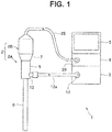
- an endoscope system 1 includes an endoscope 2 configured to be inserted into a subject and pick up an image of an object in the subject such as a living tissue and output the image as an image pickup signal, a light source apparatus 3 configured to supply illumination light for illuminating the object to the endoscope 2, a video processor 4 configured to apply signal processing to the image pickup signal outputted from the endoscope 2 to thereby generate and output an observation image or the like, and a monitor 5 configured to display the observation image or the like outputted from the video processor 4 on a screen.
- Fig. 1 is a diagram illustrating a configuration of main parts of the endoscope system including a diagnosis assisting apparatus according to the embodiment.
- the endoscope 2 is constructed of an optical visual tube 2A provided with an elongated insertion portion 6 and a camera unit 2B attachable/detachable to/from an eyepiece part 7 of the optical visual tube 2A.
- the optical visual tube 2A is constructed of the elongated insertion portion 6 inserted into the subject, a grasping portion 8 provided at a proximal end portion of the insertion portion 6, and an eyepiece part 7 provided at a proximal end portion of the grasping portion 8.
- a light guide 11 configured to transmit illumination light supplied via a cable 13a is inserted through the insertion portion 6.
- Fig. 2 is a diagram for describing an example of an internal configuration of the endoscope system in Fig. 1 .
- an emission end portion of the light guide 11 is disposed in the vicinity of an illumination lens 15 at a distal end portion of the insertion portion 6.
- An incident end portion of the light guide 11 is disposed at a light guide pipe sleeve 12 provided in the grasping portion 8.
- a light guide 13 for transmitting illumination light supplied from the light source apparatus 3 is inserted into the cable 13a. Furthermore, a connection member (not shown) attachable/detachable to/from the light guide pipe sleeve 12 is provided at one end portion of the cable 13a. A light guide connector 14 attachable/detachable to/from the light source apparatus 3 is provided at the other end portion of the cable 13a.
- An illumination window (not shown) provided with the illumination lens 15 for emitting illumination light transmitted by the light guide 11 to outside and an objective window (not shown) provided with an objective lens 17 for obtaining an optical image corresponding to light incident from outside are provided adjacent to each other on a distal end face of the insertion portion 6.
- a relay lens 18 for transmitting an optical image obtained by the objective lens 17 to the eyepiece part 7 is provided inside the insertion portion 6.
- an eyepiece lens 19 configured to allow an optical image transmitted by the relay lens 18 to be observed by naked eye is provided inside the eyepiece part 7.
- the camera unit 2B is provided with a fluorescence image pickup system configured to pick up an image of fluorescence as return light incident via the eyepiece lens 19 in a fluorescence observation mode and generate a fluorescence image, and a white light image pickup system configured to pick up an image of reflected light of white light as return light incident via the eyepiece lens 19 in a white light observation mode and generate a white light image.
- the fluorescence image pickup system and the white light image pickup system are divided into two optical axes orthogonal to each other by a dichroic prism 21 having a spectral characteristic that reflects white light and transmits fluorescence.
- the camera unit 2B is configured to include a signal cable 28 provided with a signal connector 29 attachable/detachable to/from the video processor 4 at an end portion.
- the fluorescence image pickup system of the camera unit 2B is provided with an excitation light cut filter 22 configured to have a spectral characteristic so as to cut a wavelength band EW of excitation light emitted from the light source apparatus 3, an image forming optical system 23 configured to form an image of fluorescence that passes through the dichroic prism 21 and the excitation light cut filter 22 and an image pickup device 24 configured to pick up an image of fluorescence formed by the image forming optical system 23.
- the image pickup device 24 is constructed of, for example, a high sensitivity monochrome CCD.
- the image pickup device 24 is configured to perform image pickup operation corresponding to an image pickup device drive signal outputted from the video processor 4.
- the image pickup device 24 is configured to pick up an image of fluorescence formed by the image forming optical system 23 and generate and output a fluorescence image corresponding to the imaged fluorescence.
- the white light image pickup system of the camera unit 2B is provided with an image forming optical system 25 configured to form an image of white light reflected by the dichroic prism 21 and an image pickup device 26 configured to pick up an image of white light, an image of which is formed by the image forming optical system 25.
- the image pickup device 26 is constructed of a color CCD for which a primary color based or a complementary color based color filter is provided on an image pickup surface.
- the image pickup device 26 is also configured to perform image pickup operation corresponding to an image pickup device drive signal outputted from the video processor 4.
- the image pickup device 26 is also configured to pick up an image of white light, an image of which is formed by the image forming optical system 25 and generate and output a white light image corresponding to the imaged white light.
- the camera unit 2B is provided with a signal processing circuit 27 configured to apply predetermined signal processing (correlation double sampling processing, gain adjustment processing, A/D conversion processing and the like) to the fluorescence image outputted from the image pickup device 24 and the white light image outputted from the image pickup device 26 and output the fluorescence image and the white light image subjected to the predetermined signal processing to the video processor 4 to which the signal cable 28 is connected.
- predetermined signal processing correlation double sampling processing, gain adjustment processing, A/D conversion processing and the like
- the light source apparatus 3 is constructed of a white light generation section 31, an excitation light generation section 32, dichroic mirrors 33 and 34, a condensing lens 35 and a light source control section 36.
- the white light generation section 31 is constructed of, for example, a lamp or an LED configured to emit wideband white light.
- the white light generation section 31 is configured to switch between a lighting state and a non-lighting state under the control of the light source control section 36.
- the white light generation section 31 is configured to generate white light having a light quantity corresponding to the control of the light source control section 36.
- the excitation light generation section 32 is provided with an LED or the like configured to emit light (excitation light) of a predetermined wavelength band including an excitation wavelength of a fluorescent agent administered into a subject.
- the excitation light generation section 32 is configured to switch between a lighting state and a light-off state under the control of the light source control section 36.
- the excitation light generation section 32 is also configured to generate excitation light having a light quantity corresponding to the control of the light source control section 36.
- the dichroic mirror 33 is formed so as to have an optical characteristic configured to transmit white light emitted from the white light generation section 31 to the condensing lens 35 side and reflect excitation light emitted from the excitation light generation section 32 to the condensing lens 35 side, for example.
- the dichroic mirror 34 is formed so as to have an optical characteristic configured to reflect the excitation light emitted from the excitation light generation section 32 to the dichroic mirror 33 side, for example.
- the condensing lens 35 is configured to condense the light incident via the dichroic mirror 33 so as to be emitted to the light guide 13.
- the light source control section 36 is configured to perform control on the white light generation section 31 and the excitation light generation section 32 according to an illumination control signal outputted from the video processor 4.
- the video processor 4 is constructed of an image pickup device drive section 41, an image input section 42, a region identification processing section 43, a calculation processing section 44, a storage section 45, an image processing section 46, an input I/F (interface) 52, and a control section 53.
- the image pickup device drive section 41 is provided with, for example, a driver circuit.
- the image pickup device drive section 41 is also configured to generate and output an image pickup device drive signal under the control of the control section 53.
- the image input section 42 is provided with, for example, a buffer memory and is configured to store images for one frame sequentially outputted from the signal processing circuit 27 of the camera unit 2B and output the stored images frame by frame to the control section 53.
- the image input section 42 is configured to output white light images stored in a white light observation mode frame by frame to the image processing section 46 under the control of the control section 53.
- the image input section 42 is configured to output fluorescence images stored in a fluorescence observation mode to the region identification processing section 43 and the image processing section 46 frame by frame under the control of the control section 53.
- the region identification processing section 43 is configured to apply a labeling process to fluorescence images sequentially outputted frame by frame from the image input section 42 under the control of the control section 53, make a reference region Ar (which will be described later) and a region of interest Ai (which will be described later) included in the fluorescence images identifiable and output the fluorescence images subjected to the labeling process to the calculation processing section 44.
- the calculation processing section 44 is provided with, for example, a calculation processing circuit.
- the calculation processing section 44 is configured to perform a calculation process for calculating a calculation value indicating an intensity ratio of fluorescence of the region of interest Ai to the reference region Ar based on a luminance value of each pixel included in the reference region Ar of fluorescence images sequentially outputted frame by frame from the region identification processing section 43 and a luminance value of each pixel included in the region of interest Ai of the fluorescence images under the control of the control section 53.
- the calculation processing section 44 is configured to output the calculation value obtained as a processing result of the aforementioned calculation process to the storage section 45 and/or the image processing section 46 under the control of the control section 53.
- the storage section 45 is provided with, for example, a memory and is configured to assign a time stamp to the calculation value outputted from the calculation processing section 44 and store the calculation value.
- the image processing section 46 is provided with an image processing circuit or the like to perform predetermined image processing.
- the image processing section 46 is configured to apply predetermined image processing to the white light images sequentially outputted frame by frame from the image input section 42 in the white light observation mode under the control of the control section 53, thereby generate a white light observation image and output the generated white light observation image to the monitor 5.
- the image processing section 46 is configured to apply predetermined image processing to the fluorescence images sequentially outputted frame by frame from the image input section 42 in the fluorescence observation mode under the control of the control section 53, thereby generate a fluorescence observation image and output the generated fluorescence observation image to the monitor 5.
- the image processing section 46 is configured to perform a process for causing the monitor 5 to display diagnosis assisting information (which will be described later) based on the fluorescence image outputted from the region identification processing section 43, the calculation value outputted from the calculation processing section 44 and the calculation value read from the storage section 45 in the fluorescence observation mode under the control of the control section 53.
- the input I/F 52 is provided with one or more input apparatuses that can give an instruction corresponding to a user's operation. More specifically, the input I/F 52 is provided with an observation mode changeover switch (not shown) configured to be able to give an instruction for setting (switching) the observation mode of the endoscope system 1 to either the white light observation mode or the fluorescence observation mode according to the user's operation, for example.
- the input I/F 52 is provided with a diagnosis assisting information display switch (not shown) configured to be able to set (switch) a display of diagnosis assisting information in the fluorescence observation mode to either ON or OFF according to the user's operation, for example.
- the input I/F 52 is constructed of a pointing device (not shown) capable of giving an instruction for setting each of the reference region Ar and the region of interest Ai within the fluorescence observation image displayed on the monitor 5 in the fluorescence observation mode according to the user's operation.
- the control section 53 is provided with, for example, a CPU and is configured to generate an illumination control signal to emit illumination light corresponding to the observation mode of the endoscope system 1 based on the instruction issued by the observation mode changeover switch of the input I/F 52 and output the illumination control signal to the light source control section 36.
- the control section 53 is configured to control each of the image pickup device drive section 41, the image input section 42 and the image processing section 46 so as to perform operation corresponding to the observation mode of the endoscope system 1 based on the instruction issued by the observation mode changeover switch of the input I/F 52.
- the control section 53 is configured to control the region identification processing section 43, the calculation processing section 44 and the image processing section 46 so as to extract each of the reference region Ar and the region of interest Ai from among the fluorescence images outputted from the image input section 42 based on an instruction issued by the pointing device of the input I/F 52 and display the diagnosis assisting information which is information that visualizes a fluorescence generation state of the region of interest Ai with respect to the extracted reference region Ar on the monitor 5.
- the user such as an operator connects the respective sections of the endoscope system 1, turns on the power, and then operates the input I/F 52 and thereby gives an instruction for setting the observation mode of the endoscope system 1 to the white light observation mode.
- the control section 53 Upon detecting that the white light observation mode is set, the control section 53 generates an illumination control signal for emitting white light from the light source apparatus 3 and outputs the illumination control signal to the light source control section 36. Upon detecting that the white light observation mode is set, the control section 53 controls the image pickup device drive section 41 so as to drive the image pickup device 26 of the camera unit 2B and stop driving of the image pickup device 24 of the camera unit 2B.
- the light source control section 36 performs control to set the white light generation section 31 to a lighting state and set the excitation light generation section 32 to a non-lighting state in accordance with the illumination control signal outputted from the control section 53.
- the image pickup device drive section 41 generates an image pickup device drive signal to stop image pickup operation under the control of the control section 53 and outputs the image pickup device drive signal to the image pickup device 24, and generates an image pickup device drive signal to perform image pickup operation during a predetermined exposure period EA and a predetermined reading period RA and outputs the image pickup device drive signal to the image pickup device 26.
- control section 53 controls the image input section 42 so as to output white light images sequentially outputted from the camera unit 2B frame by frame to the image processing section 46. Furthermore, upon detecting that the white light observation mode is set, the control section 53 controls the image processing section 46 so as to perform a predetermined image process on the white light images sequentially outputted from the image input section 42 frame by frame.
- the white light observation image is displayed on the monitor 5.
- the user inserts the insertion portion 6 into the subject while watching the white light observation image displayed on the monitor 5, and thereby disposes the distal end portion of the insertion portion 6 in the vicinity of a desired object.
- the user operates the input I/F 52 to give an instruction for setting the observation mode of the endoscope system 1 to the fluorescence observation mode.
- the control section 53 Upon detecting that the fluorescence observation mode is set, the control section 53 generates an illumination control signal for causing the light source apparatus 3 to emit excitation light and outputs the illumination control signal to the light source control section 36. Moreover, upon detecting that the fluorescence observation mode is set, the control section 53 controls the image pickup device drive section 41 so as to drive the image pickup device 24 of the camera unit 2B and stop driving the image pickup device 26 of the camera unit 2B.
- the light source control section 36 In response to the illumination control signal outputted from the control section 53, the light source control section 36 performs control to set the white light generation section 31 to a non-lighting state and set the excitation light generation section 32 to a lighting state.
- the image pickup device drive section 41 Under the control of the control section 53, the image pickup device drive section 41 generates an image pickup device drive signal to stop image pickup operation, outputs the image pickup device drive signal to the image pickup device 26, generates an image pickup device drive signal to cause the image pickup device 26 to perform image pickup operation for a predetermined exposure period EB and for a predetermined reading period RB, and outputs the image pickup device drive signal to the image pickup device 24.
- the control section 53 controls the image input section 42 so as to output fluorescence images sequentially outputted from the camera unit 2B to the image processing section 46 frame by frame.
- the control section 53 controls the image processing section 46 so as to apply a predetermined image process to fluorescence images sequentially outputted from the image input section 42 frame by frame.
- the user operates the input I/F 52 while watching the fluorescence observation image displayed on the monitor 5 and thereby gives an instruction for switching the setting of the display of the diagnosis assisting information from OFF to ON.
- control section 53 Upon detecting that the display of the diagnosis assisting information is set to ON, the control section 53 controls the image processing section 46 so as to display a character string or the like for urging settings of the reference region Ar and the region of interest Ai within the fluorescence observation image together with a fluorescence observation image.
- the user By operating the input I/F 52 while watching the character string displayed on the monitor 5 together with the fluorescence observation image, the user gives instructions for setting one reference region Ar to be handled as a reference of the fluorescence generation state and one or more region of interests Ai to be handled as comparison targets of the fluorescence generation state respectively from the fluorescence generation region included in the fluorescence observation image.
- the reference region Ar and the region of interest Ai of the present embodiment are assumed to be set as pixel regions provided with one or more pixels.
- the control section 53 provided with a function as a region extraction section performs processes for extracting the reference region Ar and the region of interest Ai respectively from among fluorescence images outputted from the image input section 42 based on instructions issued by the input I/F 52.
- Fig. 3 is a diagram illustrating an example of a fluorescence image used for processing by the diagnosis assisting apparatus according to the embodiment.
- Fig. 4 is a diagram illustrating an example of a case where the reference region Ar, the region of interest Ai1 and the region of interest Ai2 are extracted from the fluorescence image in Fig. 3 .
- the control section 53 controls the region identification processing section 43, the calculation processing section 44 and the image processing section 46 so as to display information on an intensity ratio of current fluorescence of the region of interest Ai1 to the reference region Ar and information on an intensity ratio of current fluorescence of the region of interest Ai2 to the reference region Ar on the monitor 5 as diagnosis assisting information.
- the region identification processing section 43 applies a labeling process to fluorescence images sequentially outputted frame by frame from the image input section 42, thereby makes the reference region Ar, the region of interests Ai1 and Ai2 included in the fluorescence images identifiable respectively and outputs the fluorescence images subjected to the labeling process to the calculation processing section 44.
- the calculation processing section 44 performs a calculation process for acquiring an average value or a maximum value of a luminance value of each pixel of the reference region Ar included in fluorescence images sequentially outputted from the region identification processing section 43 frame by frame as a representative value RV, calculating a calculation value AV1 which is a value of a ratio obtained by dividing the luminance value of the region of interest Ai1 included in the fluorescence image by the representative value RV for each pixel of the region of interest Ai1 and calculating a calculation value AV2 which is a value of a ratio obtained by dividing the luminance value of the region of interest Ai2 included in the fluorescence image by the representative value RV for each pixel of the region of interest Ai2.
- the calculation processing section 44 outputs the calculation values AV1 and AV2 of each pixel obtained as the processing result of the aforementioned calculation process to the storage section 45 and the image processing section 46 respectively.
- the image processing section 46 Under the control of the control section 53, the image processing section 46 performs a process for acquiring color information corresponding to each pixel of the region of interests Ai1 and Ai2 included in fluorescence images sequentially outputted frame by frame from the region identification processing section 43 from among a plurality of pieces of color information predetermined based on the magnitudes of the calculation values AV1 and AV2 outputted from the calculation processing section 44 and performs a process for outputting diagnosis assisting images which are colored region of interests Ai1 and Ai2 of the fluorescence images using the acquired color information to the monitor 5.
- a diagnosis assisting image shown in Fig. 5 can be displayed on the monitor 5.
- Fig. 5 is a diagram illustrating an example of the diagnosis assisting image generated by the diagnosis assisting apparatus according to the embodiment.
- the diagnosis assisting image in Fig. 5 for example, information indicating the intensity ratio of the current fluorescence of the region of interest Ai1 to the reference region Ar is displayed on the monitor 5 with a color C1 and information indicating the intensity ratio of the current fluorescence of the region of interest Ai2 to the reference region Ar is displayed on the monitor 5 with a color C2. That is, the diagnosis assisting image in Fig. 5 includes, as diagnosis assisting information, the color C1 which is color information that visualizes the intensity ratio of the current fluorescence of the region of interest Ai1 to the reference region Ar and the color C2 which is color information that visualizes the intensity ratio of the current fluorescence of the region of interest Ai2 to the reference region Ar.
- the present embodiment is not limited to one that performs the aforementioned process, but may also be one that performs a process for displaying information indicating a variation over time of an intensity ratio of fluorescence as the diagnosis assisting information, as will be described later, for example. Note that specific description relating to parts to which existing operation or the like is applicable will be omitted hereinafter as appropriate for simplicity of description.
- the control section 53 controls the region identification processing section 43, the calculation processing section 44 and the image processing section 46 so as to display on the monitor 5, a variation over time of the intensity ratio of fluorescence of the region of interest Ai1 to the reference region Ar and a variation over time of the intensity ratio of fluorescence of the region of interest Ai2 to the reference region Ar as diagnosis assisting information.
- the region identification processing section 43 applies a labeling process to fluorescence images sequentially outputted from the image input section 42 frame by frame, thereby makes the reference region Ar, and the region of interests Ai1 and Ai2 identifiable respectively and outputs the fluorescence images subjected to the labeling process to the calculation processing section 44.
- the storage section 45 performs a process for assigning a time stamp indicating the same time to the calculation values AV3 and AV4 simultaneously inputted from the calculation processing section 44 and storing the calculation values AV3 and AV4.
- the calculation values AV3 and AV4 obtained as the processing result of the calculation processing section 44 are stored in the storage section 45 frame by frame using the time Tf corresponding to a time immediately after setting the reference region Ar, the region of interest Ai1 and the region of interest Ai2 as a starting point.
- the image processing section 46 performs a process for reading the calculation values AV3 stored in time sequence in the storage section 45, plotting the read calculation values AV3 arranged in time sequence on a graph and outputting the graph to the monitor 5 as diagnosis assisting information.
- the image processing section 46 performs a process for reading calculation values AV4 stored in time sequence in the storage section 45, plotting the read calculation values AV4 arranged in time sequence on a graph and outputting the graph to the monitor 5 as diagnosis assisting information.
- Fig. 6 is a diagram illustrating an example of the diagnosis assisting information generated by the diagnosis assisting apparatus according to the embodiment.
- variations over time in the calculation value AV3 using the time Tf as a starting point are displayed on the monitor 5 as a plurality of black points and variations over time in the calculation value AV4 using the time Tf as a starting point are displayed on the monitor 5 as a plurality of white points.
- the present embodiment is not limited to one in which variations over time in the calculation values AV3 and AV4 are displayed as diagnosis assisting information, but a rate of variations over time in the calculation values AV3 and AV4 may also be displayed as diagnosis assisting information, for example.
- the present embodiment is not limited to one in which the aforementioned processes are performed, but may also be one in which a process is performed for displaying a value of an intensity ratio of fluorescence at a desired pixel position within the region of interest as the diagnosis assisting information as will be described below, for example.
- control section 53 controls the image processing section 46 so as to display a character string that urges a selection of one pixel position from the extracted region of interest Ai1 and region of interest Ai2 or the like, together with the fluorescence observation image.
- the user While watching the character string displayed on the monitor 5 together with the fluorescence observation image, the user operates the input I/F 52 and thereby gives an instruction for selecting one interested pixel PT from among the reference region Ar, the region of interest Ai1 and the region of interest Ai2.
- the control section 53 specifies an interested pixel PT from among fluorescence images outputted from the image input section 42 and controls the region identification processing section 43, the calculation processing section 44 and the image processing section 46 so as to display on the monitor 5, a value of an intensity ratio of the current fluorescence of the interested pixel PT to the reference region Ar.
- the region identification processing section 43 applies a labeling process to fluorescence images sequentially outputted from the image input section 42 frame by frame, thereby makes the reference region Ar, the region of interests Ai1 and Ai2 included in the fluorescence image identifiable respectively and outputs the fluorescence images subjected to the labeling process to the calculation processing section 44.
- the image processing section 46 Under the control of the control section 53, the image processing section 46 performs a process for outputting the calculation value AV5 outputted from the calculation processing section 44 to the monitor 5 as diagnosis assisting information.
- the current calculation value AV5 at the interested pixel PT selected from the region of interests Ai1 and Ai2 is displayed on the monitor 5 as diagnosis assisting information.
- the present embodiment is not limited to those which perform the above-described processes, and, for example, the embodiment may also perform a process for displaying on the monitor 5, a predetermined character string for indicating that the calculation value AV3 and/or the calculation value AV4 vary over time to reach a predetermined value TH1.
- the present embodiment is not limited to those which perform the above-described processes, and, for example, the embodiment may also perform a process for displaying with blinking on the monitor 5, a pixel group in which the calculation value AV1 varies over time to reach a predetermined value TH2 and a pixel group in which the calculation value AV2 changes over time to reach the predetermined value TH2 among the respective pixels included in the region of interests Ai1 and Ai2.
- the present embodiment is not limited to those which perform the above-described processes, and, for example, the embodiment may also perform a process for displaying on the monitor 5, a time period required from the time Tf to Tg when the calculation value AV3 and/or calculation value AV4 vary over time to reach a predetermined value TH3 at a time Tg.
- the user may operate the input I/F 52 to give an instruction for setting a region where the reference fluorescent substance having a known fluorescence characteristic for excitation light emitted from the light source apparatus 3 is disposed as the reference region Ar.
- the reference region Ar is set using such a method, for example, auxiliary calibration means for fluorescence observation or the like disclosed in Japanese Patent Application Laid-Open Publication No. 2005-300540 may be used as a reference fluorescent substance.
- the present embodiment may also be configured to perform such a process as to extract the region where the reference fluorescent substance is disposed as the reference region Ar based on a fluorescence image obtained by picking up an image of the reference fluorescent substance having a known fluorescence characteristic for excitation light emitted from the light source apparatus 3.
- a fluorescence image obtained by picking up an image of the reference fluorescent substance having a known fluorescence characteristic for excitation light emitted from the light source apparatus 3.
- Fig. 7 is a diagram illustrating an example of a configuration of the fluorescence member used together with the diagnosis assisting apparatus according to the embodiment.
- the fluorescence member 101 is formed as a flat plate member having a square shape in a plan view as shown in, for example, Fig. 7 . Note that the fluorescence member 101 may also be formed in a different shape in a plan view such as a star shape as long as it includes a straight line which is not existent in a living body.
- the fluorescence member 101 is provided with a reference fluorescent substance 102 having a known fluorescence characteristic for excitation light emitted from the light source apparatus 3 and a frame member 103 provided so as to surround an outer edge portion of the reference fluorescent substance 102 as shown in Fig. 7 .
- the reference fluorescent substance 102 is formed by covering the surface of the fluorescent substance such as quantum dots with glass.
- the frame member 103 is formed using a non-fluorescent member that generates no fluorescence corresponding to excitation light emitted from the light source apparatus 3 such as black PEEK (polyether ether ketone) resin.
- Fig. 8 is a diagram illustrating an example of the fluorescence image picked up when the fluorescence member in Fig. 7 is arranged.
- control section 53 Upon detecting that the display of diagnosis assisting information is set to ON, the control section 53 performs a process for specifying the inner region surrounded by the frame member 103 as a region where the reference fluorescent substance 102 exists based on a fluorescence image outputted from the image input section 42 and extracting the specified region as the reference region Ar.
- control section 53 performs processes such as applying edge extraction to a fluorescence image outputted from the image input section 42 to thereby generate an edge image, applying Hough transform to the edge image generated to thereby extract a linear shape, specifying the inner region surrounded by the extracted linear shape as the region where the reference fluorescent substance 102 exists and extracting the specified region as the reference region Ar.
- the monitor 5 can display diagnosis assisting information that visualizes a fluorescence generation state of one or more region of interests Ai with respect to one reference region Ar.
- diagnosis assisting information that visualizes a fluorescence generation state of one or more region of interests Ai with respect to one reference region Ar.
- the present embodiment may also be configured to display only one piece of diagnosis assisting information on the monitor 5 or display a plurality of pieces of diagnosis assisting information on the monitor 5 simultaneously.
- the present embodiment may also be configured to display on the monitor 5, diagnosis assisting information superimposed on the fluorescence observation image or display the diagnosis assisting information or diagnosis assisting image in a display region different from the display region of the fluorescence observation image on the monitor 5.
Landscapes
- Health & Medical Sciences (AREA)
- Life Sciences & Earth Sciences (AREA)
- Surgery (AREA)
- Physics & Mathematics (AREA)
- Engineering & Computer Science (AREA)
- Optics & Photonics (AREA)
- General Health & Medical Sciences (AREA)
- Medical Informatics (AREA)
- Biomedical Technology (AREA)
- Veterinary Medicine (AREA)
- Nuclear Medicine, Radiotherapy & Molecular Imaging (AREA)
- Pathology (AREA)
- Radiology & Medical Imaging (AREA)
- Biophysics (AREA)
- Public Health (AREA)
- Heart & Thoracic Surgery (AREA)
- Animal Behavior & Ethology (AREA)
- Molecular Biology (AREA)
- General Physics & Mathematics (AREA)
- Signal Processing (AREA)
- Multimedia (AREA)
- Astronomy & Astrophysics (AREA)
- Quality & Reliability (AREA)
- Computer Vision & Pattern Recognition (AREA)
- Theoretical Computer Science (AREA)
- Endoscopes (AREA)
- Instruments For Viewing The Inside Of Hollow Bodies (AREA)
- Closed-Circuit Television Systems (AREA)
Applications Claiming Priority (2)
| Application Number | Priority Date | Filing Date | Title |
|---|---|---|---|
| JP2014239157 | 2014-11-26 | ||
| PCT/JP2015/078992 WO2016084504A1 (fr) | 2014-11-26 | 2015-10-14 | Dispositif d'aide au diagnostic et procédé d'affichage d'informations d'aide au diagnostic |
Publications (2)
| Publication Number | Publication Date |
|---|---|
| EP3141178A1 true EP3141178A1 (fr) | 2017-03-15 |
| EP3141178A4 EP3141178A4 (fr) | 2018-02-21 |
Family
ID=56074082
Family Applications (1)
| Application Number | Title | Priority Date | Filing Date |
|---|---|---|---|
| EP15862891.7A Withdrawn EP3141178A4 (fr) | 2014-11-26 | 2015-10-14 | Dispositif d'aide au diagnostic et procédé d'affichage d'informations d'aide au diagnostic |
Country Status (5)
| Country | Link |
|---|---|
| US (1) | US20170086659A1 (fr) |
| EP (1) | EP3141178A4 (fr) |
| JP (1) | JP6013665B1 (fr) |
| CN (1) | CN106659360A (fr) |
| WO (1) | WO2016084504A1 (fr) |
Cited By (1)
| Publication number | Priority date | Publication date | Assignee | Title |
|---|---|---|---|---|
| US11176665B2 (en) | 2017-04-24 | 2021-11-16 | Olympus Corporation | Endoscopic image processing device and endoscopic image processing method |
Families Citing this family (12)
| Publication number | Priority date | Publication date | Assignee | Title |
|---|---|---|---|---|
| WO2018203383A1 (fr) * | 2017-05-02 | 2018-11-08 | オリンパス株式会社 | Dispositif de traitement d'image et programme de traitement d'image |
| JP6978604B2 (ja) * | 2018-07-10 | 2021-12-08 | オリンパス株式会社 | 内視鏡装置、内視鏡装置の作動方法及びプログラム |
| JP7079849B2 (ja) * | 2018-08-20 | 2022-06-02 | 富士フイルム株式会社 | 医療画像処理システム |
| CN112752535B (zh) * | 2018-09-26 | 2024-04-05 | 富士胶片株式会社 | 医用图像处理装置和内窥镜系统以及医用图像处理装置的工作方法 |
| JP7017646B2 (ja) * | 2018-10-26 | 2022-02-08 | オリンパス株式会社 | 内視鏡用画像処理装置、及び、内視鏡用画像処理装置の作動方法、並びに、内視鏡用画像処理プログラム |
| JP7137684B2 (ja) | 2019-02-26 | 2022-09-14 | オリンパス株式会社 | 内視鏡装置、プログラム、内視鏡装置の制御方法及び処理装置 |
| JP6921886B2 (ja) * | 2019-03-19 | 2021-08-18 | キヤノン株式会社 | 情報処理装置および情報処理方法 |
| JP7451170B2 (ja) * | 2019-12-20 | 2024-03-18 | エヌ・ティ・ティ・コミュニケーションズ株式会社 | 情報処理装置、情報処理方法およびプログラム |
| JP7417712B2 (ja) * | 2020-03-09 | 2024-01-18 | オリンパス株式会社 | 医療用画像処理装置、医療用撮像装置、医療用観察システム、医療用画像処理装置の作動方法およびプログラム |
| CN115315210B (zh) * | 2020-04-09 | 2026-01-02 | 奥林巴斯株式会社 | 图像处理装置、图像处理方法、导航方法以及内窥镜系统 |
| US12193645B2 (en) * | 2020-09-18 | 2025-01-14 | Stryker Corporation | Systems and methods for fluorescence visualization |
| CN115375641A (zh) * | 2022-08-12 | 2022-11-22 | 杭州海康慧影科技有限公司 | 一种生成荧光染色图像的方法、装置及存储介质 |
Family Cites Families (24)
| Publication number | Priority date | Publication date | Assignee | Title |
|---|---|---|---|---|
| FR2671405B1 (fr) * | 1991-01-04 | 1994-07-08 | Inst Nat Sante Rech Med | Dispositif de mesure du ph d'une cible, procede d'utilisation dudit dispositif et ses applications. |
| JP2001137173A (ja) * | 1999-11-11 | 2001-05-22 | Fuji Photo Film Co Ltd | 蛍光画像測定方法および装置 |
| JP2004024932A (ja) * | 2002-06-21 | 2004-01-29 | Nok Corp | 中空糸膜モジュール |
| JP4373726B2 (ja) * | 2003-07-23 | 2009-11-25 | Hoya株式会社 | 自家蛍光観察装置 |
| US20060211071A1 (en) * | 2004-12-14 | 2006-09-21 | Millennium Pharmaceuticals, Inc. | Device for aggregating, imaging and analyzing thrombi and a method of use |
| WO2008044492A1 (fr) * | 2006-10-13 | 2008-04-17 | Olympus Corporation | procédé d'observation au microscope de l'intérieur du corps d'un petit animal |
| JP5019866B2 (ja) * | 2006-12-25 | 2012-09-05 | オリンパス株式会社 | 蛍光内視鏡及び蛍光内視鏡の作動方法 |
| JP2009201940A (ja) * | 2008-02-29 | 2009-09-10 | Hoya Corp | 内視鏡光源システム、内視鏡光源装置、内視鏡プロセッサ、および内視鏡ユニット |
| JP4585050B1 (ja) * | 2009-03-30 | 2010-11-24 | オリンパスメディカルシステムズ株式会社 | 蛍光観察装置 |
| JP5356191B2 (ja) * | 2009-11-26 | 2013-12-04 | オリンパス株式会社 | 蛍光観察装置 |
| JP5555002B2 (ja) * | 2010-02-10 | 2014-07-23 | オリンパス株式会社 | 蛍光内視鏡装置 |
| JP5669416B2 (ja) * | 2010-03-23 | 2015-02-12 | オリンパス株式会社 | 蛍光観察装置 |
| JP5622461B2 (ja) * | 2010-07-07 | 2014-11-12 | オリンパス株式会社 | 画像処理装置、画像処理方法、および画像処理プログラム |
| WO2012114934A1 (fr) * | 2011-02-21 | 2012-08-30 | オリンパス株式会社 | Dispositif d'observation à fluorescence |
| JP6006199B2 (ja) * | 2011-03-31 | 2016-10-12 | オリンパス株式会社 | 蛍光観察装置 |
| JPWO2013015120A1 (ja) * | 2011-07-22 | 2015-02-23 | オリンパス株式会社 | 蛍光内視鏡装置 |
| JP5750381B2 (ja) * | 2012-02-13 | 2015-07-22 | 株式会社日立製作所 | 領域抽出処理システム |
| JP5979904B2 (ja) * | 2012-02-20 | 2016-08-31 | キヤノン株式会社 | 画像処理装置、眼科撮影システム、及び画像処理方法 |
| CN104105442B (zh) * | 2012-03-01 | 2016-01-20 | 株式会社日立医疗器械 | 医用图像显示装置及医用图像显示方法 |
| WO2013187148A1 (fr) * | 2012-06-15 | 2013-12-19 | オリンパス株式会社 | Dispositif de traitement d'image, système de microscope, système d'endoscope et procédé de traitement d'image |
| JP5993237B2 (ja) * | 2012-07-25 | 2016-09-14 | オリンパス株式会社 | 蛍光観察装置 |
| EP2910173A4 (fr) * | 2012-10-18 | 2016-06-01 | Olympus Corp | Dispositif et procédé de traitement d'image |
| JP6289462B2 (ja) * | 2013-06-28 | 2018-03-07 | キヤノン株式会社 | 画像処理装置及び画像処理方法 |
| JP6030035B2 (ja) * | 2013-09-27 | 2016-11-24 | 富士フイルム株式会社 | 蛍光観察装置、内視鏡システム及びプロセッサ装置並びに作動方法 |
-
2015
- 2015-10-14 EP EP15862891.7A patent/EP3141178A4/fr not_active Withdrawn
- 2015-10-14 JP JP2016538152A patent/JP6013665B1/ja active Active
- 2015-10-14 WO PCT/JP2015/078992 patent/WO2016084504A1/fr not_active Ceased
- 2015-10-14 CN CN201580032472.8A patent/CN106659360A/zh active Pending
-
2016
- 2016-12-07 US US15/371,831 patent/US20170086659A1/en not_active Abandoned
Cited By (1)
| Publication number | Priority date | Publication date | Assignee | Title |
|---|---|---|---|---|
| US11176665B2 (en) | 2017-04-24 | 2021-11-16 | Olympus Corporation | Endoscopic image processing device and endoscopic image processing method |
Also Published As
| Publication number | Publication date |
|---|---|
| WO2016084504A1 (fr) | 2016-06-02 |
| JP6013665B1 (ja) | 2016-10-25 |
| EP3141178A4 (fr) | 2018-02-21 |
| US20170086659A1 (en) | 2017-03-30 |
| JPWO2016084504A1 (ja) | 2017-04-27 |
| CN106659360A (zh) | 2017-05-10 |
Similar Documents
| Publication | Publication Date | Title |
|---|---|---|
| EP3141178A1 (fr) | Dispositif d'aide au diagnostic et procédé d'affichage d'informations d'aide au diagnostic | |
| US9392942B2 (en) | Fluoroscopy apparatus and fluoroscopy system | |
| CN103906458B (zh) | 内窥镜装置和医用系统 | |
| US9949645B2 (en) | Fluorescence imaging apparatus for identifying fluorescence region based on specified processing condition and superimposing fluorescence region at corresponding region in return-light image | |
| US9052286B2 (en) | Fluorescence endoscope apparatus | |
| CN112105286A (zh) | 内窥镜装置、内窥镜操作方法及程序 | |
| US10856805B2 (en) | Image processing device, living-body observation device, and image processing method | |
| WO2019123827A1 (fr) | Système endoscope et processeur d'endoscope | |
| WO2018047369A1 (fr) | Système d'endoscope | |
| WO2014171332A1 (fr) | Dispositif de capture et dispositif de traitement d'image | |
| EP3275358A1 (fr) | Dispositif de diagnostic endoscopique, procédé de traitement d'image, programme et support d'enregistrement | |
| JP4495513B2 (ja) | 蛍光内視鏡装置 | |
| CN105338882B (zh) | 摄像装置 | |
| CN105188509B (zh) | 内窥镜系统和内窥镜系统的工作方法 | |
| JP2021129648A (ja) | 医療用信号処理装置、キャップ部材および医療用信号処理方法 | |
| CN108778088A (zh) | 活体观察系统 | |
| JP6205531B1 (ja) | 内視鏡システム | |
| JP2002143079A (ja) | 電子内視鏡装置 | |
| WO2016157998A1 (fr) | Dispositif de diagnostic endoscopique, procédé de traitement d'image, programme et support d'enregistrement | |
| JPWO2017047142A1 (ja) | 内視鏡装置及び内視鏡システム | |
| US11582427B2 (en) | Medical image processing apparatus and medical observation system | |
| JP7235540B2 (ja) | 医療用画像処理装置及び医療用観察システム | |
| US20200288955A1 (en) | Light source device, medical observation system, illumination method, and computer readable recording medium | |
| US20230347169A1 (en) | Phototherapy device, phototherapy method, and computer-readable recording medium | |
| CN112739250A (zh) | 医用图像处理装置、处理器装置、医用图像处理方法及程序 |
Legal Events
| Date | Code | Title | Description |
|---|---|---|---|
| STAA | Information on the status of an ep patent application or granted ep patent |
Free format text: STATUS: THE INTERNATIONAL PUBLICATION HAS BEEN MADE |
|
| PUAI | Public reference made under article 153(3) epc to a published international application that has entered the european phase |
Free format text: ORIGINAL CODE: 0009012 |
|
| STAA | Information on the status of an ep patent application or granted ep patent |
Free format text: STATUS: REQUEST FOR EXAMINATION WAS MADE |
|
| 17P | Request for examination filed |
Effective date: 20161209 |
|
| AK | Designated contracting states |
Kind code of ref document: A1 Designated state(s): AL AT BE BG CH CY CZ DE DK EE ES FI FR GB GR HR HU IE IS IT LI LT LU LV MC MK MT NL NO PL PT RO RS SE SI SK SM TR |
|
| AX | Request for extension of the european patent |
Extension state: BA ME |
|
| A4 | Supplementary search report drawn up and despatched |
Effective date: 20180124 |
|
| RIC1 | Information provided on ipc code assigned before grant |
Ipc: A61B 1/04 20060101ALI20180118BHEP Ipc: G02B 23/24 20060101ALI20180118BHEP Ipc: H04N 7/18 20060101ALI20180118BHEP Ipc: A61B 1/00 20060101AFI20180118BHEP |
|
| DAV | Request for validation of the european patent (deleted) | ||
| DAX | Request for extension of the european patent (deleted) | ||
| STAA | Information on the status of an ep patent application or granted ep patent |
Free format text: STATUS: THE APPLICATION IS DEEMED TO BE WITHDRAWN |
|
| 18D | Application deemed to be withdrawn |
Effective date: 20180821 |