EP3141188A1 - Dispositif d'imagerie pour tomodensitométrie à faisceau conique - Google Patents
Dispositif d'imagerie pour tomodensitométrie à faisceau conique Download PDFInfo
- Publication number
- EP3141188A1 EP3141188A1 EP16195074.6A EP16195074A EP3141188A1 EP 3141188 A1 EP3141188 A1 EP 3141188A1 EP 16195074 A EP16195074 A EP 16195074A EP 3141188 A1 EP3141188 A1 EP 3141188A1
- Authority
- EP
- European Patent Office
- Prior art keywords
- detector
- source
- path
- turntable
- subject
- Prior art date
- Legal status (The legal status is an assumption and is not a legal conclusion. Google has not performed a legal analysis and makes no representation as to the accuracy of the status listed.)
- Withdrawn
Links
- 238000007408 cone-beam computed tomography Methods 0.000 title claims abstract description 8
- 238000003384 imaging method Methods 0.000 title claims description 76
- 230000005855 radiation Effects 0.000 claims abstract description 51
- 238000000034 method Methods 0.000 claims description 12
- 238000010304 firing Methods 0.000 claims 1
- 210000003414 extremity Anatomy 0.000 description 66
- 210000002414 leg Anatomy 0.000 description 56
- 230000032258 transport Effects 0.000 description 48
- 210000003127 knee Anatomy 0.000 description 26
- 210000002683 foot Anatomy 0.000 description 18
- 210000003423 ankle Anatomy 0.000 description 6
- 230000008901 benefit Effects 0.000 description 6
- 238000002591 computed tomography Methods 0.000 description 6
- 210000003484 anatomy Anatomy 0.000 description 5
- 238000013459 approach Methods 0.000 description 5
- 206010073306 Exposure to radiation Diseases 0.000 description 4
- 210000003141 lower extremity Anatomy 0.000 description 4
- 210000000617 arm Anatomy 0.000 description 3
- 238000002059 diagnostic imaging Methods 0.000 description 3
- 210000001513 elbow Anatomy 0.000 description 3
- 210000002832 shoulder Anatomy 0.000 description 3
- 210000001364 upper extremity Anatomy 0.000 description 3
- 210000000544 articulatio talocruralis Anatomy 0.000 description 2
- 230000000295 complement effect Effects 0.000 description 2
- 210000003811 finger Anatomy 0.000 description 2
- 210000004247 hand Anatomy 0.000 description 2
- 210000001503 joint Anatomy 0.000 description 2
- 210000000629 knee joint Anatomy 0.000 description 2
- 238000002601 radiography Methods 0.000 description 2
- 210000000707 wrist Anatomy 0.000 description 2
- 241000606643 Anaplasma centrale Species 0.000 description 1
- 208000019901 Anxiety disease Diseases 0.000 description 1
- 230000036506 anxiety Effects 0.000 description 1
- 230000006835 compression Effects 0.000 description 1
- 238000007906 compression Methods 0.000 description 1
- 230000001010 compromised effect Effects 0.000 description 1
- 238000010586 diagram Methods 0.000 description 1
- 230000003028 elevating effect Effects 0.000 description 1
- 210000000056 organ Anatomy 0.000 description 1
- 238000002360 preparation method Methods 0.000 description 1
- 230000008569 process Effects 0.000 description 1
- 230000004044 response Effects 0.000 description 1
- 238000004088 simulation Methods 0.000 description 1
Images









Classifications
-
- A—HUMAN NECESSITIES
- A61—MEDICAL OR VETERINARY SCIENCE; HYGIENE
- A61B—DIAGNOSIS; SURGERY; IDENTIFICATION
- A61B6/00—Apparatus or devices for radiation diagnosis; Apparatus or devices for radiation diagnosis combined with radiation therapy equipment
- A61B6/02—Arrangements for diagnosis sequentially in different planes; Stereoscopic radiation diagnosis
- A61B6/03—Computed tomography [CT]
- A61B6/032—Transmission computed tomography [CT]
- A61B6/035—Mechanical aspects of CT
-
- A—HUMAN NECESSITIES
- A61—MEDICAL OR VETERINARY SCIENCE; HYGIENE
- A61B—DIAGNOSIS; SURGERY; IDENTIFICATION
- A61B6/00—Apparatus or devices for radiation diagnosis; Apparatus or devices for radiation diagnosis combined with radiation therapy equipment
- A61B6/02—Arrangements for diagnosis sequentially in different planes; Stereoscopic radiation diagnosis
- A61B6/03—Computed tomography [CT]
- A61B6/032—Transmission computed tomography [CT]
-
- A—HUMAN NECESSITIES
- A61—MEDICAL OR VETERINARY SCIENCE; HYGIENE
- A61B—DIAGNOSIS; SURGERY; IDENTIFICATION
- A61B6/00—Apparatus or devices for radiation diagnosis; Apparatus or devices for radiation diagnosis combined with radiation therapy equipment
- A61B6/02—Arrangements for diagnosis sequentially in different planes; Stereoscopic radiation diagnosis
- A61B6/03—Computed tomography [CT]
-
- A—HUMAN NECESSITIES
- A61—MEDICAL OR VETERINARY SCIENCE; HYGIENE
- A61B—DIAGNOSIS; SURGERY; IDENTIFICATION
- A61B6/00—Apparatus or devices for radiation diagnosis; Apparatus or devices for radiation diagnosis combined with radiation therapy equipment
- A61B6/04—Positioning of patients; Tiltable beds or the like
-
- A—HUMAN NECESSITIES
- A61—MEDICAL OR VETERINARY SCIENCE; HYGIENE
- A61B—DIAGNOSIS; SURGERY; IDENTIFICATION
- A61B6/00—Apparatus or devices for radiation diagnosis; Apparatus or devices for radiation diagnosis combined with radiation therapy equipment
- A61B6/40—Arrangements for generating radiation specially adapted for radiation diagnosis
- A61B6/4064—Arrangements for generating radiation specially adapted for radiation diagnosis specially adapted for producing a particular type of beam
- A61B6/4085—Cone-beams
-
- A—HUMAN NECESSITIES
- A61—MEDICAL OR VETERINARY SCIENCE; HYGIENE
- A61B—DIAGNOSIS; SURGERY; IDENTIFICATION
- A61B6/00—Apparatus or devices for radiation diagnosis; Apparatus or devices for radiation diagnosis combined with radiation therapy equipment
- A61B6/44—Constructional features of apparatus for radiation diagnosis
- A61B6/4429—Constructional features of apparatus for radiation diagnosis related to the mounting of source units and detector units
- A61B6/4435—Constructional features of apparatus for radiation diagnosis related to the mounting of source units and detector units the source unit and the detector unit being coupled by a rigid structure
- A61B6/4441—Constructional features of apparatus for radiation diagnosis related to the mounting of source units and detector units the source unit and the detector unit being coupled by a rigid structure the rigid structure being a C-arm or U-arm
-
- A—HUMAN NECESSITIES
- A61—MEDICAL OR VETERINARY SCIENCE; HYGIENE
- A61B—DIAGNOSIS; SURGERY; IDENTIFICATION
- A61B6/00—Apparatus or devices for radiation diagnosis; Apparatus or devices for radiation diagnosis combined with radiation therapy equipment
- A61B6/44—Constructional features of apparatus for radiation diagnosis
- A61B6/4429—Constructional features of apparatus for radiation diagnosis related to the mounting of source units and detector units
- A61B6/4452—Constructional features of apparatus for radiation diagnosis related to the mounting of source units and detector units the source unit and the detector unit being able to move relative to each other
-
- A—HUMAN NECESSITIES
- A61—MEDICAL OR VETERINARY SCIENCE; HYGIENE
- A61B—DIAGNOSIS; SURGERY; IDENTIFICATION
- A61B6/00—Apparatus or devices for radiation diagnosis; Apparatus or devices for radiation diagnosis combined with radiation therapy equipment
- A61B6/46—Arrangements for interfacing with the operator or the patient
- A61B6/461—Displaying means of special interest
- A61B6/466—Displaying means of special interest adapted to display 3D data
-
- A—HUMAN NECESSITIES
- A61—MEDICAL OR VETERINARY SCIENCE; HYGIENE
- A61B—DIAGNOSIS; SURGERY; IDENTIFICATION
- A61B6/00—Apparatus or devices for radiation diagnosis; Apparatus or devices for radiation diagnosis combined with radiation therapy equipment
- A61B6/50—Apparatus or devices for radiation diagnosis; Apparatus or devices for radiation diagnosis combined with radiation therapy equipment specially adapted for specific body parts; specially adapted for specific clinical applications
- A61B6/505—Apparatus or devices for radiation diagnosis; Apparatus or devices for radiation diagnosis combined with radiation therapy equipment specially adapted for specific body parts; specially adapted for specific clinical applications for diagnosis of bone
Definitions
- the invention relates generally to diagnostic imaging and in particular to cone beam imaging systems used for obtaining volume images of extremities.
- 3-D volume imaging has proved to be a valuable diagnostic tool that offers significant advantages over earlier 2-D radiographic imaging techniques for evaluating the condition of internal structures and organs.
- 3-D imaging of a patient or other subject has been made possible by a number of advancements, including the development of high-speed imaging detectors, such as digital radiography (DR) detectors that enable multiple images to be taken in rapid succession.
- DR digital radiography
- Cone beam (CB) computed tomography (CT) (CBCT) or cone beam CT technology offers considerable promise as one type of diagnostic tool for providing 3-D volume images.
- Cone beam CT systems capture volumetric data sets by using a high frame rate digital radiography (DR) detector and an x-ray source, typically affixed to a gantry that rotates about the object to be imaged, directing, from various points along its orbit around the subject, a divergent cone beam of x-rays toward the subject.
- the CBCT system captures projections throughout the rotation, for example, one 2-D projection image at every degree of rotation.
- the projections are then reconstructed into a 3D volume image using various techniques.
- filtered back projection approaches are filtered back projection approaches.
- 3-D images of diagnostic quality can be generated using CBCT systems and technology, a number of technical challenges remain.
- CBCT Imaging of legs, arms, and other extremities can be hampered by physical obstruction from a paired extremity. This is an obstacle that is encountered in obtaining CBCT image projections for the human leg or knee, for example. Not all imaging positions around the knee are accessible; the patient's own anatomy prevents the radiation source and image detector from being positioned over a portion of the scan circumference.
- Figure 1 shows the circular scan paths for a radiation source 22 and detector 24 when imaging the right knee R of a patient as a subject 20.
- Various positions of radiation source 22 and detector are shown in dashed line form.
- Source 22, placed at some distance from the knee, can be positioned at different points over an arc of about 200 degrees; with any larger arc, left knee L blocks the way.
- Detector 24, smaller than source 22 and typically placed very near subject 20, can be positioned between the patient's right and left knees and is thus capable of positioning over the full circular orbit.
- a full 360 degree orbit of the source and detector is not needed for conventional CBCT imaging; instead, sufficient information for image reconstruction can be obtained with an orbital scan range that just exceeds 180 degrees by the angle of the cone beam itself, for example. However, in some cases it can be difficult to obtain much more than about 180 degree revolution for imaging the knee or other joints and other applications. Moreover, there can be diagnostic situations in which obtaining projection images over a certain range of angles has advantages, but patient anatomy blocks the source, detector, or both from imaging over that range.
- one way around this problem is to arrange the patient in a pose such that the subject leg is extended into a CBCT scanning apparatus and the paired leg is supported in some other way or bent with respect to the subject leg, such as at a right angle.
- This is the approach used, for example, in the CT scanner device taught in U.S. Patent No. 7,394,888 entitled "CT Scanner for Lower Extremities" to Sukovic et al.
- the other leg In the methods of the Sukovic et al. '888 disclosure, the other leg must either be lifted out of place or spread at a distance, or is relaxed while the subject leg is lifted out of place and extended into the scanner equipment. This arrangement can be particularly disadvantageous for a number of reasons.
- the Sukovic et al. '888 apparatus may obtain an image when there is excessive strain, or insufficient strain, or poorly directed strain, on the joint.
- Another issue with conventional approaches relates to imaging of a load-bearing extremity such as the human leg. Because of the inability to image the leg under a normal load, as the patient is in a standing position, various artificial ways of mimicking load conditions have been attempted. Such approaches have used various types of braces, compression devices, and supports. As one example intended to remedy the shortcomings of conventional imaging techniques, the Sukovic et al. '888 disclosure teaches simulating the normal loading of the leg by elevating the leg to a non-standing position, then applying an external force against the leg. However, it can be readily appreciated that while this type of simulation allows some approximation of load-bearing limb response, it can be inaccurate. The knee or ankle joint, under some artificially applied load and at an angle not taken when standing, may not behave exactly as it does when bearing the patient's weight in a standing position.
- Another difficulty with the Sukovic et al. '888 apparatus and with other devices designed to address knee and lower leg imaging relates to poor image quality.
- the CBCT sequence requires that the detector be up close to the subject and the source of the cone beam radiation be at a sufficient distance from the subject. This provides the best image and reduces image truncation and consequent lost data.
- Positioning the subject midway between the detector and the source, as Sukovic et al. '888 apparatus and with other devices require, not only noticeably compromises image quality, but also places the patient too near the radiation source, so that radiation levels are considerably higher.
- German patent publication DE 10146915 One example of this strategy is shown in German patent publication DE 10146915 .
- Imaging of the foot and ankle presents additional obstacles for CBCT projection image capture.
- a number of improvements are needed, including the following: (i) improved placement of the radiation source and detector to provide acceptable radiation levels and image quality throughout the scanning sequence; (ii) system flexibility for imaging at different heights with respect to the rotational axis of the source and detector, including the flexibility to allow imaging with the patient standing or seated comfortably, such as with a foot in an elevated position, for example; (iii) improved patient accessibility, so that the patient does not need to contort, twist, or unduly stress limbs or joints that may have been injured in order to provide images of those body parts; (iv) improved ergonomics for obtaining the CBCT image, allowing the patient to stand with normal posture, for example.
- the present invention provides apparatus for cone beam computed tomography of an extremity of a patient, the apparatus comprising: a digital radiation detector; a first device to move the detector along at least a portion of a circular detector path, the portion of the detector path extending so that the detector moves both at least partially around a first extremity of the patient and between the first extremity and a second, adjacent extremity of the patient, the detector path having a radius R 1 that is sufficiently long to allow the first extremity of the patient to be positioned approximately at a center of the detector path; a radiation source; a second device to move the source along at least a portion of a concentric circular source path having a radius R 2 greater than radius R 1 , radius R 2 being sufficiently long to allow adequate radiation exposure of the first extremity for an image capture by the detector; and a first circumferential gap in the source path to allow the second extremity to be positioned in the first circumferential gap during the image capture.
- the present invention provides an apparatus for cone beam computed tomography of a portion of a subject leg of a patient who is standing on the subject leg and its paired leg, the apparatus comprising: a digital radiation detector; a detector transport that defines a detector path for movement of the digital radiation detector along a first circular arc, wherein the first circular arc has a radius R1 with respect to a central point within the subject leg and wherein the first circular arc extends through the space between the subject leg and its paired leg; a radiation source; a radiation source transport that defines a radiation source path for movement of the radiation source along a second circular arc of a second radius R2, larger than radius R1, with respect to the central point in the subject leg, wherein the second circular arc lies outside the space between the subject leg and its paired leg; and a circumferential gap in the radiation source path for placement of the subject leg.
- the term "extremity” has its meaning as conventionally understood in diagnostic imaging parlance, referring to knees, legs, ankles, fingers, hands, wrists, elbows, arms, and shoulders and any other anatomical extremity.
- subject is used to describe the extremity of the patient that is imaged, such as the "subject leg", for example.
- paired extremity is used in general to refer to any anatomical extremity wherein normally two or more are present on the same patient. In the context of the present invention, the paired extremity is not imaged; only the subject extremity is imaged.
- arc or, alternately, “circular arc” has its conventional meaning as being a portion of a circle of less than 360 degrees or, considered alternately, of less than 2n radians for a given radius.
- Embodiments of the present invention address the difficulties of lower extremity imaging by providing an imaging apparatus that defines orbital source and detector paths, concentric about a center point, wherein components that provide the source and detector paths are configured to allow patient access prior to and following imaging and configured to allow the patient to stand with normal posture during the CBCT image capture series.
- this capability is effected by using a detector transport device that has a circumferential access opening allowing positioning of the extremity, wherein the detector transport device is revolved about the positioned extremity once it is in place, enclosing the extremity as it is revolved through at least a portion of the scan.
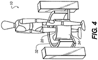
- FIG. 2 The perspective and top views of Figure 2 show how the scanning pattern is provided using various embodiments of a CBCT imaging apparatus 10 according to the present invention.
- a detector path 28 of a suitable radius R1 from a central axis A is provided by a first device, a detector transport 34.
- a source path 26 of a second, larger radius R2 is provided by a second device, a source transport 32.
- the extremity, subject 20 is substantially centered along central axis A so that central axis A can be considered as a line through points in subject 20.
- the limiting geometry for image capture is due to the arc of source transport 32, blocked by patient anatomy, such as by a paired limb, to typically about 200 degrees, as noted previously. This defines a partial circular sector, bounded by this arc and radii at start and end-of-scan.
- Detector transport 34 while capable of a fully circular orbit because it can be moved between the standing patient's legs, follows the necessary complementary arc to that of source transport 32. Patient access before scanning is eased by providing a circumferential gap 38 in detector transport 34. With detector transport 34 in the open position shown in Figure 3 , the patient can freely move in and out of position for imaging. When the patient is properly in position, detector transport 34 is revolved about axis A, substantially 180 degrees. This orbital movement confines the extremity more narrowly and places detector 24, not visible in Figures 2 - 4 due to the detector transport 34 housing, in position near subject 20 for obtaining the first projection image in sequence.
- Circumferential gap 38 not only allows access for positioning of the subject leg or other extremity, but also allows sufficient space for the patient to stand in normal posture during imaging, placing the subject leg for imaging in the central position of axis A ( Figure 2 ) and the non-imaged paired leg within the space defined by circumferential gap 38.
- Circumferential gap 38 extends approximately 180 degrees plus the fan angle, which is determined by source-detector geometry and distance.
- FIG. 5 The top views of Figure 5 show the sequence for patient access for imaging apparatus 10.
- an open access position 40 circumferential gap 38 permits access of the extremity so that it can be centered in position along central axis A.
- the outline of the foot corresponding to an open access position 42 indicates positioning of the patient and is shown for reference.
- the left leg is the subject imaged; the paired right leg would lie within or just outside circumferential gap 38.
- detector transport 34 or a hooded cover or other member that defines this transport path, can be revolved into position, closing the detector portion of circumferential gap 38, as shown in a revolving transport position 44.
- a transport in place position 46 shows detector transport 34 in suitable position for executing the CBCT imaging sequence.
- FIG. 6 The top views of Figure 6 continue the operational sequence begun in Figure 5 and show the sequence for obtaining CBCT projections at a number of angular positions when using imaging apparatus 10.
- the source and detector are diametrically opposite at each position during the CBCT scan and projection imaging.
- the sequence begins at a begin scan position 50, with radiation source 22 and detector 24 at initial positions to obtain an image at a first angle. Then, both radiation source 22 and detector 24 revolve about axis A as represented in interim scan positions 52, 54, 56, and 58. Imaging terminates at an end scan position 60.
- source 22 and detector 24 are in diametrically opposing positions relative to subject 20 at each imaging angle. Throughout the scanning cycle, detector 24 is within a short distance D1 of subject 20. Source 22 is positioned beyond a longer distance D2 of subject 20.
- the positioning of source and detector components can be carried out by separate actuators, one for each transport path, or by a single rotatable member, as described in more detail subsequently. It should be noted that scanning motion in the opposite direction, that is, clockwise with respect to the example shown in Figure 6 , is also possible, with the corresponding changes in initial and terminal scan positions.
- imaging apparatus 10 provides various features of imaging apparatus 10 by the capability to move both source and detector transports 32 and 34 along the axis direction as a unit, as shown in the perspective view of Figure 7 .
- a vertical support 70 provides vertical transport of the imaging apparatus, so that the source and detector can be translated upwards or downwards in the direction of the central axis in order to suit patients of different heights and to image different portions of the leg. The height adjustment can be made before or after the patient's subject leg to be imaged is enclosed by detector transport 34 using the setup sequence of Figure 5 .
- vertical support 70 also allows rotation of the CBCT imaging apparatus 10 to allow imaging of an extremity that is disposed horizontally or is extended at some oblique angle other than vertical.
- Figures 8A and 8B show perspective views of knee imaging in a horizontal position, with the patient seated and the leg outwardly extended. Full 360 degree rotation about an axis Q is possible. It should be noted that, with this application, similar patient accessibility applies, with detector transport 34 revolved into position once the extremity is centered in place. Further height adjustment is also possible, such as for arm, elbow, or shoulder imaging, as shown in Figure 9 .
- detector transport 34 simplifies patient access and provides sufficient imaging path for CBCT imaging, since the angular limitation of the orbital imaging path is due to source obstruction, rather than to the detector path.
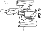
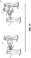
- detector transport 34 could fully encircle the limb, as shown in the examples of Figures 10 and 11 .
- radiation source 22 and detector 24 each orbit the subject along an arc with radii R2 and R1, respectively.
- a source actuator could be used, cooperating with a separate, complementary detector actuator that is part of detector transport 34.
- two independent actuator devices, one in each transport assembly, can be separately controlled and coordinated by an external logic controller to move source 22 and detector 24 along their respective arcs, in unison, about subject 20.
- source and detector transport components are mechanically linked to a single revolving or rotating assembly.
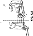
- One such arrangement shown at the right in Figure 12A and enlarged in Figure 12B , provides source and detector transports 32 and 34 using a single mechanical assembly, a rotating member 68, on a turntable 64 that revolves about central axis of rotation A and provides the needed radii for source 22 and detector 24.
- detector 24 rides along the surface of the C-shaped turntable 64, orbiting the subject at radius R1.
- Source 22 is connected to turntable 64 along an arm 66 that provides the longer radius R2.
- Circumferential gap 38 extends across both source and detector paths.
- rotating member 68 on turntable 64 can be encased in one or more housings, thereby providing similar appearance to imaging apparatus 10 shown in Figures 7-11 , for example.
- This type of arrangement has advantages for isolating the patient from moving components and for alleviating at least some of the patient anxiety that might be caused by automatically moving components during imaging.
- Figure 14A shows sources and detector transports 32 and 34 and source and detector 22 and 24 components as they are fitted within covers 80 that protect moving mechanical parts and help to prevent patient contact with moving components.
- Figure 14B shows the covered system with internal components in begin and end scan positions 50 and 60 respectively, when using the scan sequence described earlier with reference to Figure 6 .
- FIG. 13 , 15 , and 16 show how patient access is provided using this mechanical arrangement.
- rotating member 68 is swung around the positioned extremity, to a start position 72, as shown at the bottom in Figure 15 . Imaging begins at this position and continues as rotating member 68 revolves source and detector components about axis A.
- rotating member 68 moves in a clockwise direction. Counter-clockwise rotation would also be possible.
- Rotating member 68 can also be used with an imaging configuration for upper extremities, as shown in Figure 17 . Because none of the patient anatomy blocks the transport path, a full circular orbit is permitted for scanning with this configuration. Again, full 360 degree rotation of the components in the plane of rotating member 68 is possible, about axis Q.
- Imaging of the ankle and foot is also possible with CBCT imaging apparatus 10.
- the allowable angular range for foot imaging is more constrained than the range for leg and knee imaging.
- the top view of Figure 18 shows, for example, that the angular range for CBCT scanning of the foot, for a standing patient, is about 50 degrees less than that for knee imaging, for example.
- a range of optional devices can also be provided to facilitate the imaging process.
- a horizontal or vertical foot support can be provided for support of the patient's foot.
- the foot support can be adjustable to some oblique angle between horizontal and vertical, such as at a 33 degree or 45 degree angle for example.
Landscapes
- Health & Medical Sciences (AREA)
- Life Sciences & Earth Sciences (AREA)
- Engineering & Computer Science (AREA)
- Medical Informatics (AREA)
- Heart & Thoracic Surgery (AREA)
- Animal Behavior & Ethology (AREA)
- Biophysics (AREA)
- Nuclear Medicine, Radiotherapy & Molecular Imaging (AREA)
- Optics & Photonics (AREA)
- Pathology (AREA)
- Radiology & Medical Imaging (AREA)
- Biomedical Technology (AREA)
- Physics & Mathematics (AREA)
- Molecular Biology (AREA)
- Surgery (AREA)
- High Energy & Nuclear Physics (AREA)
- General Health & Medical Sciences (AREA)
- Public Health (AREA)
- Veterinary Medicine (AREA)
- Pulmonology (AREA)
- Theoretical Computer Science (AREA)
- Orthopedic Medicine & Surgery (AREA)
- Dentistry (AREA)
- Oral & Maxillofacial Surgery (AREA)
- Human Computer Interaction (AREA)
- Apparatus For Radiation Diagnosis (AREA)
- Magnetic Resonance Imaging Apparatus (AREA)
Applications Claiming Priority (3)
| Application Number | Priority Date | Filing Date | Title |
|---|---|---|---|
| US17509109P | 2009-05-04 | 2009-05-04 | |
| US12/771,250 US8348506B2 (en) | 2009-05-04 | 2010-04-30 | Extremity imaging apparatus for cone beam computed tomography |
| EP10772373.6A EP2427111B1 (fr) | 2009-05-04 | 2010-05-03 | Dispositif d'imagerie pour tomodensitométrie à faisceau conique |
Related Parent Applications (1)
| Application Number | Title | Priority Date | Filing Date |
|---|---|---|---|
| EP10772373.6A Division EP2427111B1 (fr) | 2009-05-04 | 2010-05-03 | Dispositif d'imagerie pour tomodensitométrie à faisceau conique |
Publications (1)
| Publication Number | Publication Date |
|---|---|
| EP3141188A1 true EP3141188A1 (fr) | 2017-03-15 |
Family
ID=43030331
Family Applications (2)
| Application Number | Title | Priority Date | Filing Date |
|---|---|---|---|
| EP10772373.6A Not-in-force EP2427111B1 (fr) | 2009-05-04 | 2010-05-03 | Dispositif d'imagerie pour tomodensitométrie à faisceau conique |
| EP16195074.6A Withdrawn EP3141188A1 (fr) | 2009-05-04 | 2010-05-03 | Dispositif d'imagerie pour tomodensitométrie à faisceau conique |
Family Applications Before (1)
| Application Number | Title | Priority Date | Filing Date |
|---|---|---|---|
| EP10772373.6A Not-in-force EP2427111B1 (fr) | 2009-05-04 | 2010-05-03 | Dispositif d'imagerie pour tomodensitométrie à faisceau conique |
Country Status (5)
| Country | Link |
|---|---|
| US (8) | US8348506B2 (fr) |
| EP (2) | EP2427111B1 (fr) |
| CN (1) | CN102421368B (fr) |
| ES (1) | ES2609067T3 (fr) |
| WO (1) | WO2010129037A2 (fr) |
Families Citing this family (36)
| Publication number | Priority date | Publication date | Assignee | Title |
|---|---|---|---|---|
| US8348506B2 (en) * | 2009-05-04 | 2013-01-08 | John Yorkston | Extremity imaging apparatus for cone beam computed tomography |
| FI123379B (fi) | 2010-04-29 | 2013-03-15 | Planmed Oy | Lääketieteellinen tietokonetomografialaitteisto |
| FI125531B (fi) * | 2010-04-29 | 2015-11-13 | Planmed Oy | Lääketieteellinen röntgenkuvauslaitteisto |
| US8989469B2 (en) * | 2010-12-20 | 2015-03-24 | The Board Of Trustees Of The Leland Stanford Junior University | Systems and methods for simultaneous acquisition of scatter and image projection data in computed tomography |
| DE102012211330B4 (de) * | 2012-06-29 | 2020-08-13 | Siemens Healthcare Gmbh | Intra-operative Bildgebungsvorrichtung |
| EP2903522B1 (fr) | 2012-10-08 | 2016-09-21 | Carestream Health, Inc. | Appareil d'imagerie d'extrémité pour tomographie assistée par ordinateur à faisceau conique |
| US10136871B2 (en) * | 2013-10-10 | 2018-11-27 | Carestream Health, Inc. | Extremity imaging for animals |
| US9808211B2 (en) | 2013-11-12 | 2017-11-07 | Carestream Health, Inc. | Head and neck imager |
| WO2015154021A1 (fr) * | 2014-04-04 | 2015-10-08 | Colorado State University Research Foundation | Dispositif de balayage ouvert pour animaux de grande taille |
| US10548540B2 (en) * | 2014-07-22 | 2020-02-04 | Carestream Health, Inc. | Extremity imaging apparatus for cone beam computed tomography |
| WO2016020859A1 (fr) | 2014-08-07 | 2016-02-11 | Imaginalis S.R.L. | Dispositif d'imagerie radiologique à fonctionnement amélioré |
| UA112351C2 (uk) * | 2014-11-10 | 2016-08-25 | Сергій Іванович Мірошниченко | Рентгенівська установка для томосинтезу |
| EP3261544B1 (fr) * | 2015-02-23 | 2020-04-22 | Imaginalis S.r.l. | Appareil radiologique pour l'imagerie des extrémités inférieures |
| US9949703B2 (en) | 2015-03-17 | 2018-04-24 | Carestream Health, Inc. | Extremity imaging apparatus |
| US10136870B2 (en) | 2015-06-11 | 2018-11-27 | Carestream Health, Inc. | Extremity imaging for animals |
| US10925552B2 (en) * | 2016-03-25 | 2021-02-23 | Carestream Health, Inc. | CBCT imaging system with curved detector |
| CN108882909A (zh) * | 2016-04-11 | 2018-11-23 | 专用成像有限责任公司 | 具有集成驱动系统的自包含低成本ct系统 |
| US10874369B2 (en) * | 2016-11-02 | 2020-12-29 | Carestream Health, Inc. | Geometric calibration in a cone beam computed tomography system |
| CN110121299A (zh) * | 2016-11-04 | 2019-08-13 | 霍罗吉克公司 | 医学成像装置和操作医学成像装置的方法 |
| EP3332707B1 (fr) | 2016-12-06 | 2019-10-30 | Agfa Nv | Support pour l'arc d'un dispositif à rayons x mobile |
| US10751018B2 (en) | 2016-12-14 | 2020-08-25 | Principle Imaging Corporation | Multiple-aperture computerized tomography systems |
| US10818074B2 (en) | 2017-12-13 | 2020-10-27 | Carestream Health, Inc. | Bone segmentation and display for 3D extremity imaging |
| CN109143392B (zh) * | 2018-08-10 | 2024-07-12 | 安徽启路达光电科技有限公司 | 一种肢体安全检查仪 |
| US20200058141A1 (en) * | 2018-08-14 | 2020-02-20 | Carestream Health, Inc. | Image capture and reconstruction protocol selection system |
| CN109363704A (zh) * | 2018-10-25 | 2019-02-22 | 陈安强 | 一种锥形束ct多方向扫描仪 |
| GB2579247A (en) * | 2018-11-28 | 2020-06-17 | Hallmarq Veterinary Imaging Ltd | Apparatus for x-ray CT scanning |
| KR102171457B1 (ko) | 2018-12-03 | 2020-10-29 | 이화여자대학교 산학협력단 | 의료 영상 촬영 보조 장치 및 이를 포함하는 의료 영상 촬영 시스템 |
| WO2021010934A1 (fr) | 2019-07-12 | 2021-01-21 | Miroshnychenko Sergii | Appareil de diagnostic par rayons x basé sur un appareil de tomographie volumique à faisceau conique pour examen d'extrémités |
| CN110680372A (zh) * | 2019-10-29 | 2020-01-14 | 金阿水 | 计算机断层扫描方法及系统 |
| KR102211389B1 (ko) * | 2020-01-08 | 2021-02-03 | (주)웨버인스트루먼트 | 인공지능형 회전방식을 구현하는 3차원 골밀도 및 골연령 측정장치 |
| US11013476B1 (en) | 2020-06-08 | 2021-05-25 | SIMULATE Technologies, LLC | Weightbearing simulation assembly and methods of using the same to image a subject |
| JP7462506B2 (ja) * | 2020-07-31 | 2024-04-05 | キヤノンメディカルシステムズ株式会社 | X線コンピュータ断層撮影装置 |
| US12033281B2 (en) * | 2021-04-01 | 2024-07-09 | Sony Group Corporation | Automatic blending of human facial expression and full-body poses for dynamic digital human model creation using integrated photo-video volumetric capture system and mesh-tracking |
| JP7805731B2 (ja) * | 2021-09-07 | 2026-01-26 | キヤノンメディカルシステムズ株式会社 | X線コンピュータ断層撮影装置 |
| CN115177275A (zh) * | 2022-07-14 | 2022-10-14 | 上海涛影医疗科技有限公司 | 一种x射线成像系统及其影像采集方法 |
| CN120752664A (zh) * | 2023-01-05 | 2025-10-03 | 美国西门子医疗系统股份有限公司 | 分布式医学图像采集 |
Citations (3)
| Publication number | Priority date | Publication date | Assignee | Title |
|---|---|---|---|---|
| DE10146915A1 (de) | 2001-09-24 | 2003-04-24 | Siemens Ag | Vefahren und Bildgebungsrerät für eine 3D-Untersuchung am Patienten in aufrechter oder teilweise aufrechter Körperhaltung |
| JP2007159598A (ja) * | 2005-12-09 | 2007-06-28 | Hitachi Medical Corp | X線ct装置 |
| US7394888B2 (en) | 2005-05-02 | 2008-07-01 | Xoran Technologies, Inc. | CT scanner for lower extremities |
Family Cites Families (83)
| Publication number | Priority date | Publication date | Assignee | Title |
|---|---|---|---|---|
| US4014398A (en) | 1975-07-07 | 1977-03-29 | William Gresko | Weight distribution measuring instruments |
| US4316091A (en) | 1979-11-15 | 1982-02-16 | Emi Limited | CT Scanner |
| NL8300965A (nl) | 1983-03-17 | 1984-10-16 | Nicolaas Roelof Snijder | Stelsel voor onderzoek aan skeletdelen van het lichaam van een levend wezen, in het bijzonder de wervelkolom van het menselijk lichaam. |
| US4741015A (en) | 1986-12-05 | 1988-04-26 | B. C. Medical Compagnie Limitee | Universal X-ray unit |
| JPH02228946A (ja) | 1989-03-02 | 1990-09-11 | Toshiba Corp | X線ctスキャナ装置 |
| US5014293A (en) | 1989-10-04 | 1991-05-07 | Imatron, Inc. | Computerized tomographic x-ray scanner system and gantry assembly |
| DE4130761A1 (de) | 1991-09-16 | 1993-03-18 | Siemens Ag | Geraet zur behandlung eines lebewesens mit akustischen wellen |
| US5475729A (en) | 1994-04-08 | 1995-12-12 | Picker International, Inc. | X-ray reference channel and x-ray control circuit for ring tube CT scanners |
| JPH0723942A (ja) | 1993-07-06 | 1995-01-27 | Toshiba Corp | X線ct装置 |
| SE9401793D0 (sv) | 1994-05-24 | 1994-05-24 | Jan A G Willen | Anordning vid diagnos |
| US5448607A (en) | 1994-02-08 | 1995-09-05 | Analogic Corporation | X-ray tomography system with gantry pivot and translation control |
| US5473657A (en) | 1994-02-08 | 1995-12-05 | Analogic Corporation | X-ray tomographic scanning system |
| US5748704A (en) | 1997-03-10 | 1998-05-05 | Lunar Corporation | Peripheral bone densitometer |
| JP3664462B2 (ja) | 1997-06-04 | 2005-06-29 | 株式会社東芝 | X線診断装置 |
| US6064720A (en) | 1997-11-26 | 2000-05-16 | Picker International, Inc. | Magnetic support for removable antiscatter grid |
| US6131690A (en) | 1998-05-29 | 2000-10-17 | Galando; John | Motorized support for imaging means |
| DE19846980A1 (de) | 1998-10-12 | 1999-10-28 | Siemens Ag | CT-Gerät |
| US7016457B1 (en) | 1998-12-31 | 2006-03-21 | General Electric Company | Multimode imaging system for generating high quality images |
| JP2000197627A (ja) | 1999-01-05 | 2000-07-18 | Hitachi Medical Corp | X線ct装置 |
| US6236704B1 (en) | 1999-06-30 | 2001-05-22 | Siemens Corporate Research, Inc. | Method and apparatus using a virtual detector for three-dimensional reconstruction from x-ray images |
| JP4481392B2 (ja) | 1999-07-27 | 2010-06-16 | 株式会社東芝 | X線診断装置 |
| US6987831B2 (en) | 1999-11-18 | 2006-01-17 | University Of Rochester | Apparatus and method for cone beam volume computed tomography breast imaging |
| CN101422372B (zh) | 2000-02-18 | 2013-06-12 | 威廉博蒙特医院 | 带有平板成像器的锥面束计算机x线断层扫描系统 |
| JP2001269332A (ja) | 2000-03-24 | 2001-10-02 | Toshiba Corp | X線ct装置および治療計画用x線ct装置 |
| DE10147157A1 (de) | 2001-09-25 | 2003-04-24 | Siemens Ag | Bildgebendes System mit Aufnahmezeitanzeigevorrichtung |
| JP4282957B2 (ja) | 2001-07-10 | 2009-06-24 | 株式会社東芝 | 医用診断システム、超音波診断装置、情報表示装置、及び医用診断システムの制御方法 |
| US6872179B2 (en) | 2001-07-10 | 2005-03-29 | Kabushiki Kaisha Toshiba | Medical diagnosis system having a medical diagnosis apparatus and a display to be observed by a patient |
| US6619840B2 (en) * | 2001-10-15 | 2003-09-16 | Koninklijke Philips Electronics N.V. | Interventional volume scanner |
| US7609806B2 (en) | 2004-10-18 | 2009-10-27 | Hologic Inc. | Mammography system and method employing offset compression paddles, automatic collimations, and retractable anti-scatter grid |
| US6644852B2 (en) * | 2001-11-15 | 2003-11-11 | Ge Medical Systems Global Technology | Automatically reconfigurable x-ray positioner |
| EP1474040B1 (fr) | 2002-02-15 | 2007-10-24 | Breakaway Imaging, Llc | Portique circulaire a segment amovible pour imagerie a rayons x multidimensionnelle |
| CN100398066C (zh) | 2002-03-13 | 2008-07-02 | 分离成像有限责任公司 | 准同步多平面x射线成像的系统和方法 |
| EP2915488B1 (fr) | 2002-03-19 | 2019-06-05 | Medtronic Navigation, Inc. | Tomodensitométrie avec un détecteur suivant le mouvement d'une source à rayons x pivotable |
| AU2003245439A1 (en) | 2002-06-11 | 2003-12-22 | Breakaway Imaging, Llc | Cantilevered gantry apparatus for x-ray imaging |
| JP4522044B2 (ja) | 2002-11-15 | 2010-08-11 | キヤノン株式会社 | 放射線撮影装置 |
| US6917666B2 (en) | 2002-12-19 | 2005-07-12 | General Electric Company | System and method for table/gantry alignment in imaging systems |
| US7388941B2 (en) * | 2003-08-07 | 2008-06-17 | Xoran Technologies, Inc. | CT extremity scanner |
| US7224764B2 (en) | 2003-08-07 | 2007-05-29 | Xoran Technologies, Inc. | Stand-up CT scanner |
| WO2006042211A2 (fr) * | 2004-10-07 | 2006-04-20 | University Of Florida Research Foundation, Inc. | Systeme d'imagerie medicale radiographique utilisant une source et un detecteur montes sur robot pour capture d'image et tomographie dynamiques |
| WO2006061772A2 (fr) | 2004-12-09 | 2006-06-15 | Koninklijke Philips Electronics N.V. | Marquage a plusieurs lasers, avec localisation ct dans un passage |
| DE102005013832A1 (de) | 2005-03-24 | 2006-08-10 | Siemens Ag | Gantry für ein Computertomographiegerät und Computertomographiegerät |
| US7450623B2 (en) * | 2005-04-12 | 2008-11-11 | Eric G. Johnson | Wavelength locked laser including integrated wavelength selecting total internal reflection (TIR) structure |
| JP4690768B2 (ja) | 2005-05-13 | 2011-06-01 | 株式会社東芝 | X線診断装置 |
| DE102005030285B4 (de) | 2005-06-29 | 2007-04-19 | Siemens Ag | Computertomographiegerät und Verfahren für ein Computertomographiegerät mit einem Markierungsmittel zur positionsgenauen Markierung einer Interventionsposition mittels eines Laser-strahls auf einem zu untersuchenden Objekt |
| US8170705B2 (en) | 2005-08-19 | 2012-05-01 | Alipes, Inc. | Interactive on-demand orthotic vending machine and method of producing orthotic including disc version |
| US20070053486A1 (en) | 2005-08-23 | 2007-03-08 | Zelnik Deborah R | Methods and apparatus for nuclear tomo-cardiology scanning |
| US7476271B2 (en) | 2006-07-31 | 2009-01-13 | Hewlett-Packard Development Company, L.P. | Inkjet ink set |
| DE102006037564C5 (de) * | 2006-08-10 | 2010-09-23 | Siemens Ag | Verfahren zur Röntgenbildaufzeichnung mit einem robotergeführten C-Bogen-System sowie Aufzeichnungsvorrichtung zur Röntgenbildaufzeichnung |
| DE102006041457A1 (de) | 2006-09-04 | 2008-03-27 | Siemens Ag | Verfahren zur Unterstützung der Durchführung einer bildgestützten medizinischen Maßnahme und mit diesem Verfahren betriebene Einrichtung |
| US7460636B2 (en) | 2006-10-26 | 2008-12-02 | Moshe Ein-Gal | CT scanning system with interlapping beams |
| US7526071B2 (en) | 2007-04-06 | 2009-04-28 | Warsaw Orthopedic, Inc. | System and method for patient balance and position analysis |
| DE102007021185B4 (de) | 2007-05-05 | 2012-09-20 | Ziehm Imaging Gmbh | Röntgendiagnostikeinrichtung mit einer Vielzahl kodierter Marken und ein Verfahren zur Bestimmung der Lage von Einrichtungsteilen der Röntgendiagnostikeinrichtung |
| US20090080604A1 (en) | 2007-08-23 | 2009-03-26 | Fischer Medical Technologies, Inc. | Computed tomography breast imaging and biopsy system |
| CN101406398B (zh) | 2007-10-12 | 2013-06-19 | Ge医疗系统环球技术有限公司 | X射线成像台和x射线成像设备 |
| CN101437351A (zh) | 2007-11-16 | 2009-05-20 | Ge医疗系统环球技术有限公司 | 具防x射线泄漏的x射线系统 |
| EP2211721B1 (fr) | 2007-11-19 | 2019-07-10 | Pyronia Medical Technologies, Inc. | Système de positionnement d'un patient et procédés de radiologie de diagnostic et de radiothérapie |
| US7720196B2 (en) | 2008-01-07 | 2010-05-18 | Accuray Incorporated | Target tracking using surface scanner and four-dimensional diagnostic imaging data |
| DE102008019646A1 (de) | 2008-04-18 | 2009-10-22 | Siemens Aktiengesellschaft | Computertomographie-System |
| DE102008019656A1 (de) | 2008-04-18 | 2009-10-22 | Krauss-Maffei Wegmann Gmbh & Co. Kg | Militärisches Kraftfahrzeug |
| US7558367B1 (en) | 2008-05-13 | 2009-07-07 | General Electric Co. | Method and system for detecting breast laterality |
| US7724870B2 (en) | 2008-05-30 | 2010-05-25 | Siemens Medical Solutions Usa, Inc. | Digital tomosynthesis in robotic stereotactic radiosurgery |
| WO2009147608A1 (fr) | 2008-06-06 | 2009-12-10 | Koninklijke Philips Electronics N.V. | Procédé et appareil d’éclairage de l’intérieur d’un dispositif d’imagerie médicale |
| JP2010154992A (ja) | 2008-12-29 | 2010-07-15 | Fujifilm Corp | 放射線画像撮影制御装置、放射線画像撮影制御システム、及び放射線画像撮影制御プログラム |
| US8118488B2 (en) | 2009-01-05 | 2012-02-21 | Mobius Imaging, Llc | Mobile medical imaging system and methods |
| JP2010200929A (ja) | 2009-03-03 | 2010-09-16 | Fujifilm Corp | 放射線撮影制御方法及び装置、並びに放射線撮影制御プログラム |
| US8210745B2 (en) * | 2009-05-04 | 2012-07-03 | John Yorkston | Extremity imaging apparatus for cone beam computed tomography |
| US8348506B2 (en) * | 2009-05-04 | 2013-01-08 | John Yorkston | Extremity imaging apparatus for cone beam computed tomography |
| DE102009031165A1 (de) | 2009-06-30 | 2011-01-05 | Siemens Aktiengesellschaft | Verfahren und Vorrichtung zur Aufnahme von Röntgenbildern für eine dreidimensionale Bildrekonstruktion |
| WO2011106433A1 (fr) | 2010-02-24 | 2011-09-01 | Accuray Incorporated | Système de radiothérapie guidée par l'image comprenant un portique et méthodes d'administration de traitement associées |
| DE102010020605A1 (de) | 2010-05-14 | 2011-11-17 | Siemens Aktiengesellschaft | Medizinische Untersuchungseinrichtung zur CT-Bildgebung und zur nuklearmedizinischen Bildgebung |
| US8804901B2 (en) | 2010-06-08 | 2014-08-12 | Accuray Incorporated | Imaging methods for image-guided radiation treatment |
| EP2653105B1 (fr) | 2010-09-08 | 2015-04-15 | FUJIFILM Corporation | Dispositif et procédé de détection de mouvements corporels et appareil et procédé d'imagerie radiographique |
| WO2012139014A2 (fr) | 2011-04-07 | 2012-10-11 | Mobius Imaging, Llc | Système d'imagerie à rayons x mobile |
| CN202027591U (zh) | 2011-04-19 | 2011-11-09 | 洪常华 | 膝关节特殊体位x线摄影专用卡尺 |
| US20120289821A1 (en) | 2011-05-12 | 2012-11-15 | The Johns Hopkins University | C-arm integrated electromagnetic tracking system |
| US9265470B2 (en) | 2011-05-24 | 2016-02-23 | General Electric Company | Pivoting X-ray imaging devices |
| US8818065B2 (en) | 2011-07-01 | 2014-08-26 | Carestream Health, Inc. | Methods and apparatus for scatter correction for CBCT system and cone-beam image reconstruction |
| US20130032413A1 (en) | 2011-08-02 | 2013-02-07 | Smith Damian Jerard | Bodyweight distribution and posture evaluation system and method |
| EP2858571B1 (fr) | 2012-06-07 | 2019-01-23 | The Johns Hopkins University | Intégration de systèmes d'étalonnage quantitatif dans des scanners de tomodensitométrie |
| JP6222795B2 (ja) | 2012-06-20 | 2017-11-01 | 東芝メディカルシステムズ株式会社 | 画像診断装置及びその制御方法 |
| US9713238B2 (en) | 2012-06-27 | 2017-07-18 | Analogic Corporation | Rotating member for radiation imaging modality configured to facilitate contactless transfer of information and/or power and/or to facilitate ascertaining rotation angle of rotating member |
| EP2903522B1 (fr) | 2012-10-08 | 2016-09-21 | Carestream Health, Inc. | Appareil d'imagerie d'extrémité pour tomographie assistée par ordinateur à faisceau conique |
| JP2013066784A (ja) | 2013-01-22 | 2013-04-18 | Toshiba Corp | 乳房撮影検査用x線診断装置 |
-
2010
- 2010-04-30 US US12/771,250 patent/US8348506B2/en not_active Expired - Fee Related
- 2010-05-03 CN CN201080020339.8A patent/CN102421368B/zh not_active Expired - Fee Related
- 2010-05-03 EP EP10772373.6A patent/EP2427111B1/fr not_active Not-in-force
- 2010-05-03 EP EP16195074.6A patent/EP3141188A1/fr not_active Withdrawn
- 2010-05-03 WO PCT/US2010/001308 patent/WO2010129037A2/fr not_active Ceased
- 2010-05-03 ES ES10772373.6T patent/ES2609067T3/es active Active
-
2012
- 2012-11-20 US US13/681,579 patent/US8746972B2/en active Active
-
2014
- 2014-05-01 US US14/266,861 patent/US8998486B2/en active Active
-
2015
- 2015-03-05 US US14/639,363 patent/US9277899B2/en active Active
-
2016
- 2016-02-02 US US15/012,995 patent/US9597044B2/en not_active Expired - Fee Related
-
2017
- 2017-02-06 US US15/424,935 patent/US10010295B2/en active Active
- 2017-02-07 US US15/426,145 patent/US9770214B2/en not_active Expired - Fee Related
-
2018
- 2018-06-14 US US16/008,357 patent/US10307115B2/en not_active Expired - Fee Related
Patent Citations (3)
| Publication number | Priority date | Publication date | Assignee | Title |
|---|---|---|---|---|
| DE10146915A1 (de) | 2001-09-24 | 2003-04-24 | Siemens Ag | Vefahren und Bildgebungsrerät für eine 3D-Untersuchung am Patienten in aufrechter oder teilweise aufrechter Körperhaltung |
| US7394888B2 (en) | 2005-05-02 | 2008-07-01 | Xoran Technologies, Inc. | CT scanner for lower extremities |
| JP2007159598A (ja) * | 2005-12-09 | 2007-06-28 | Hitachi Medical Corp | X線ct装置 |
Also Published As
| Publication number | Publication date |
|---|---|
| US20160151029A1 (en) | 2016-06-02 |
| US8746972B2 (en) | 2014-06-10 |
| US9770214B2 (en) | 2017-09-26 |
| US20180296172A1 (en) | 2018-10-18 |
| US20170143285A1 (en) | 2017-05-25 |
| CN102421368B (zh) | 2015-01-07 |
| US20150173695A1 (en) | 2015-06-25 |
| ES2609067T3 (es) | 2017-04-18 |
| US8998486B2 (en) | 2015-04-07 |
| US10307115B2 (en) | 2019-06-04 |
| US20100278300A1 (en) | 2010-11-04 |
| US20130077741A1 (en) | 2013-03-28 |
| CN102421368A (zh) | 2012-04-18 |
| WO2010129037A3 (fr) | 2011-01-06 |
| US10010295B2 (en) | 2018-07-03 |
| US8348506B2 (en) | 2013-01-08 |
| US9277899B2 (en) | 2016-03-08 |
| US9597044B2 (en) | 2017-03-21 |
| EP2427111B1 (fr) | 2016-11-02 |
| EP2427111A2 (fr) | 2012-03-14 |
| EP2427111A4 (fr) | 2013-05-15 |
| WO2010129037A2 (fr) | 2010-11-11 |
| US20170156683A1 (en) | 2017-06-08 |
| US20140241490A1 (en) | 2014-08-28 |
Similar Documents
| Publication | Publication Date | Title |
|---|---|---|
| US10307115B2 (en) | Extremity imaging apparatus for cone beam computed tomography | |
| EP2555682B1 (fr) | Appareil d'imagerie d'extrémité pour tomodensitométrie à faisceau conique | |
| EP2903524B1 (fr) | Appareil d'imagerie d'extrémité pour tomographie volumique à faisceau conique | |
| US10548540B2 (en) | Extremity imaging apparatus for cone beam computed tomography | |
| US11039799B2 (en) | Bearing system for cone beam computed tomography | |
| US10307123B2 (en) | Tomosynthesis views from cone beam computed tomography data |
Legal Events
| Date | Code | Title | Description |
|---|---|---|---|
| PUAI | Public reference made under article 153(3) epc to a published international application that has entered the european phase |
Free format text: ORIGINAL CODE: 0009012 |
|
| STAA | Information on the status of an ep patent application or granted ep patent |
Free format text: STATUS: REQUEST FOR EXAMINATION WAS MADE |
|
| 17P | Request for examination filed |
Effective date: 20161021 |
|
| AC | Divisional application: reference to earlier application |
Ref document number: 2427111 Country of ref document: EP Kind code of ref document: P |
|
| AK | Designated contracting states |
Kind code of ref document: A1 Designated state(s): AL AT BE BG CH CY CZ DE DK EE ES FI FR GB GR HR HU IE IS IT LI LT LU LV MC MK MT NL NO PL PT RO SE SI SK SM TR |
|
| RIN1 | Information on inventor provided before grant (corrected) |
Inventor name: SIEWERDSEN, JEFFERY H. Inventor name: YORKSTON, JOHN Inventor name: ASENTO, ROBERT Inventor name: FOOS, DAVID H. |
|
| STAA | Information on the status of an ep patent application or granted ep patent |
Free format text: STATUS: EXAMINATION IS IN PROGRESS |
|
| 17Q | First examination report despatched |
Effective date: 20210303 |
|
| STAA | Information on the status of an ep patent application or granted ep patent |
Free format text: STATUS: THE APPLICATION HAS BEEN WITHDRAWN |
|
| 18W | Application withdrawn |
Effective date: 20210531 |