EP3141201B1 - Dispositif d'athérectomie - Google Patents
Dispositif d'athérectomie Download PDFInfo
- Publication number
- EP3141201B1 EP3141201B1 EP16187574.5A EP16187574A EP3141201B1 EP 3141201 B1 EP3141201 B1 EP 3141201B1 EP 16187574 A EP16187574 A EP 16187574A EP 3141201 B1 EP3141201 B1 EP 3141201B1
- Authority
- EP
- European Patent Office
- Prior art keywords
- catheter
- lumen
- rotatable shaft
- motor housing
- atherectomy
- Prior art date
- Legal status (The legal status is an assumption and is not a legal conclusion. Google has not performed a legal analysis and makes no representation as to the accuracy of the status listed.)
- Active
Links
Images


Classifications
-
- A—HUMAN NECESSITIES
- A61—MEDICAL OR VETERINARY SCIENCE; HYGIENE
- A61M—DEVICES FOR INTRODUCING MEDIA INTO, OR ONTO, THE BODY; DEVICES FOR TRANSDUCING BODY MEDIA OR FOR TAKING MEDIA FROM THE BODY; DEVICES FOR PRODUCING OR ENDING SLEEP OR STUPOR
- A61M1/00—Suction or pumping devices for medical purposes; Devices for carrying-off, for treatment of, or for carrying-over, body-liquids; Drainage systems
- A61M1/71—Suction drainage systems
- A61M1/77—Suction-irrigation systems
-
- A—HUMAN NECESSITIES
- A61—MEDICAL OR VETERINARY SCIENCE; HYGIENE
- A61B—DIAGNOSIS; SURGERY; IDENTIFICATION
- A61B17/00—Surgical instruments, devices or methods
- A61B17/32—Surgical cutting instruments
- A61B17/3203—Fluid jet cutting instruments
-
- A—HUMAN NECESSITIES
- A61—MEDICAL OR VETERINARY SCIENCE; HYGIENE
- A61B—DIAGNOSIS; SURGERY; IDENTIFICATION
- A61B17/00—Surgical instruments, devices or methods
- A61B17/32—Surgical cutting instruments
- A61B17/3205—Excision instruments
- A61B17/3207—Atherectomy devices working by cutting or abrading; Similar devices specially adapted for non-vascular obstructions
- A61B17/32075—Pullback cutting; combined forward and pullback cutting, e.g. with cutters at both sides of the plaque
-
- A—HUMAN NECESSITIES
- A61—MEDICAL OR VETERINARY SCIENCE; HYGIENE
- A61B—DIAGNOSIS; SURGERY; IDENTIFICATION
- A61B17/00—Surgical instruments, devices or methods
- A61B17/32—Surgical cutting instruments
- A61B17/3205—Excision instruments
- A61B17/3207—Atherectomy devices working by cutting or abrading; Similar devices specially adapted for non-vascular obstructions
- A61B17/320758—Atherectomy devices working by cutting or abrading; Similar devices specially adapted for non-vascular obstructions with a rotating cutting instrument, e.g. motor driven
-
- A—HUMAN NECESSITIES
- A61—MEDICAL OR VETERINARY SCIENCE; HYGIENE
- A61B—DIAGNOSIS; SURGERY; IDENTIFICATION
- A61B17/00—Surgical instruments, devices or methods
- A61B17/32—Surgical cutting instruments
- A61B17/3205—Excision instruments
- A61B17/3207—Atherectomy devices working by cutting or abrading; Similar devices specially adapted for non-vascular obstructions
- A61B17/320783—Atherectomy devices working by cutting or abrading; Similar devices specially adapted for non-vascular obstructions through side-hole, e.g. sliding or rotating cutter inside catheter
-
- A—HUMAN NECESSITIES
- A61—MEDICAL OR VETERINARY SCIENCE; HYGIENE
- A61B—DIAGNOSIS; SURGERY; IDENTIFICATION
- A61B17/00—Surgical instruments, devices or methods
- A61B17/32—Surgical cutting instruments
- A61B17/3205—Excision instruments
- A61B17/3207—Atherectomy devices working by cutting or abrading; Similar devices specially adapted for non-vascular obstructions
- A61B17/320758—Atherectomy devices working by cutting or abrading; Similar devices specially adapted for non-vascular obstructions with a rotating cutting instrument, e.g. motor driven
- A61B2017/320766—Atherectomy devices working by cutting or abrading; Similar devices specially adapted for non-vascular obstructions with a rotating cutting instrument, e.g. motor driven eccentric
Definitions
- This application relates to a vascular surgical apparatus, and more particularly to a minimally invasive device for removing plaque or other deposits from the interior of a vessel.
- the vascular disease of atherosclerosis is the buildup of plaque or substances inside the vessel, e.g., arterial, wall which reduces the size of the passageway through the vessel, thereby restricting blood flow.
- stenosis Such constriction or narrowing of the passage in the vessel.
- peripheral vascular disease which is atherosclerosis of the vascular extremities
- the vessel constriction is left untreated, the resulting insufficient blood flow can cause claudication and possibly require amputation of the patient's limb.
- coronary artery disease if left untreated, the blood flow through the coronary artery to the myocardium will become inadequate causing myocardial infarction and possibly leading to stroke and even death.
- bypass surgery requires opening the patient's chest, is complex, has inherent risks to the patient, is expensive and requires lengthy patient recovery time. Bypass surgery also requires use of a heart lung machine to pump the blood as the heart is stopped, which has its own risks and disadvantages. Oftentimes, the saphenous vein in the patient's leg must be utilized as a bypass graft, requiring the additional invasive leg incision which further complicates the procedure, increases surgery time, lengthens the patient's recovery time, can be painful to the patient, and increases the risk of infection.
- Balloon angioplasty is one of the minimally invasive methods for treating vessel occlusion/obstructions. Basically, a catheter having a balloon is inserted through the access artery, e.g., the femoral artery in the patient's leg or the radial artery in the arm, and advanced through the vascular system to the occluded site over a wire. The deflated balloon is placed at the occlusion and the balloon is inflated to crack and stretch the plaque and other deposits to expand the opening in the vessel.
- the access artery e.g., the femoral artery in the patient's leg or the radial artery in the arm
- Balloon angioplasty especially in coronary surgery, is frequently immediately followed by insertion of a stent, a small metallic expandable device which is placed inside the vessel wall to retain the opening which was created by the balloon.
- Balloon angioplasty has several drawbacks including difficulty in forcing the balloon through the partially occluded passageway if there is hard occlusion, the risk involved in cutting off blood flow when the balloon is fully inflated, and the frequency of restenosis after a short period of time since the plaque is essentially stretched or cracked and not removed from the vessel wall or because of the development of intimal hyperplasia.
- Atherectomy Another minimally invasive technique used to treat arteriosclerosis is referred to as atherectomy and involves removal of the plaque by a cutting or abrading instrument.
- This technique provides a minimally invasive alternative to bypass surgery techniques described above as well as can provide an advantage over balloon angioplasty methods in certain instances.
- Atherectomy procedures typically involve inserting a cutting or ablating device through the access artery, e.g., the femoral artery or the radial artery, advancing it through the vascular system to the occluded region, and rotating the device at high speed to cut through or ablate the plaque over the wire.
- the removed plaque or material can then be suctioned out of the vessel or be of such fine diameter that it is cleared by the reticuloendothelial system. Removal of the plaque in an atherectomy procedure has an advantage over balloon angioplasty plaque displacement since it debulks the material.
- Atherectomy devices examples include U.S. Patent Nos. 4,990,134 , 5,681,336 , 5,938,670 , and 6,015,420 . These devices have elliptical shaped tips which are rotated at high speeds to cut away the plaque and other deposits on the interior vessel wall. Other well-known devices are the Rotablator marketed by Boston Scientific Corp. and the Diamondback Sheath 360 and Stealth 360 marketed by CSI. Other examples of atherectomy tips are disclosed in U.S. Patent Nos. 5,217,474 and 6,096,054 and 6,676,698 . Document EP 2 913 012 A1 discloses an atherectomy device which forms the basis of the preamble of claim 1.
- a surgical atherectomy apparatus for removing particles such as plaque from an interior of a vessel, the apparatus comprising: an outer housing; a motor housing containing a motor therein; an axially fixed sheath extending from the outer housing; a catheter connected to the motor housing and having a lumen, the catheter positioned within the sheath; and a rotatable shaft positioned within the lumen of the catheter and operatively connected to the motor for rotational movement, the rotatable shaft having an atherectomy bit extending therefrom for dislodgement of particles when rotated by the motor; wherein particles dislodged by the atherectomy bit are aspirated in the lumen of the catheter in the space between an outer wall of the rotatable shaft and an inner wall of the catheter; and wherein the motor housing is positioned within the outer housing, the motor housing slidable axially between a proximal position and a distal position; and
- the particles may be aspirated by a vacuum through a tube extending from an outlet port of the catheter.
- the rotatable shaft may include a series of screw threads positioned thereon and forming a threaded region, and particles may be aspirated by rotation of the rotatable shaft and screw threads.
- the threaded region may be proximal of a distal end of the sheath.
- the distal end of the catheter may extend a second distance from a distal end of the sheath in the proximal position of the motor housing and may extend a third greater distance from the distal end of the sheath in the distal position of the motor housing.
- the rotatable shaft may have a threaded region to direct deposits proximally as the rotatable shaft is rotated.
- the outer housing may have first and second rails positioned therein, and the motor housing may be moved along the rails when moved between the retracted and extended positions.
- the catheter may have first and second lumens and the rotatable shaft may extend though the first lumen. Aspiration may be through the first lumen in a space between an outer wall of the rotatable shaft and an inner wall of the first lumen and fluid may be injected through the second lumen.
- the atherectomy bit may be positioned at a distalmost end of the shaft.
- the atherectomy bit may have abrasive coating to aid grinding of the particles.
- the atherectomy bit may be exposed in retracted and extended positions of the catheter.
- the atherectomy bit may be spaced from a distalmost end of the shaft.
- the present invention is directed to an atherectomy device (apparatus) designed for high speed rotation to remove plaque or other deposits or particles on the inside wall of the vessel to widen the blood passageway therethrough.
- the rotatable atherectomy bit or tip is positioned at a distal portion of a flexible rotatable shaft that is electrically powered (or alternatively powered by gas).
- the shaft rotates at high speed causing the cutting or ablation surface of the bit to remove the plaque and deposits (particles) to which it comes into contact.
- the atherectomy bit of the present disclosure has application in a variety of vessels and structures such as for example the coronary arteries, peripheral vessels such as the tibial artery, femoral, and popliteal, and saphenous vein bypass grafts and stents.
- the atherectomy bit is operatively connected to the motor housing such that activation of the motor rotates the shaft and bit.
- a control knob can be provided to adjust the rotational speed of the shaft and bit, and a window can be provided to visually display the speed.
- an introducer sheath or catheter is inserted through an incision in the patient's leg, and through an incision in the femoral artery.
- the device is introduced through the introducer sheath into the femoral artery, and advanced to the target artery, e.g., the coronary artery, to the treatment obstruction site.
- a guidewire in some embodiments can extend through the sheath and into the target artery so that the rotatable shaft can be inserted thereover. That is, in these embodiments, the introducer sheath is placed through a skin incision and into a vessel, e.g., the femoral artery in the patient's leg, to provide access to the target site.
- a guidewire is then inserted through the introducer sheath and advanced through the appropriate vessels to the target obstructed site, such as the peripheral or the coronary artery.
- the device is then inserted through the introducer sheath with the flexible shaft threaded over the length of the guidewire to the target obstructed site.
- the guidewire can then be removed. Actuation of the motor spins the shaft and bit so the cutting surface repeatedly comes into contact with the obstruction, e.g., plaque, to remove it from the vessel wall.
- the atherectomy device of the present disclosure provides for aspiration of the particles (deposits) dislodged by the high speed rotational movement of the rotatable atherectomy bit.
- the aspiration is through an aspiration catheter or lumen which is a fixed distance from the atherectomy bit, and the fixed distance remains constant during advancement and retraction of the atherectomy tip with respect to the device housing.
- proximal refers to components or portions closer to the user and the term distal refers to components or portions further from the user.
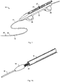
- the device 10 includes an outer housing 12, an outer sheath 14 having a lumen 15 extending therethrough, a catheter 16 with a lumen 17 extending therethrough, and a rotatable shaft 18 which supports an atherectomy tip in the form of a grinding bit or burr 20.
- the bit 20 is preferably fixedly attached to the rotatable shaft 18 such that rotation of the shaft 18 rotates the bit 20 to dislodge the particles from the vessel wall.
- the bit 20 can be positioned at the distalmost end of shaft 18 or alternatively spaced proximally of the distalmost end.
- the atherectomy bit can be eccentrically mounted on the shaft as shown in Figure 1 or alternatively concentrically mounted and symmetrical in configuration such as shown in the alternate embodiment of Figure 1A where elliptical bit 20' is concentrically mounted on shaft 18' which has a lumen to receive guidewire 86.
- Lever 22 is positioned on the housing 12 and is configured to move the catheter 16 and shaft 18. As shown, the lever 22 is a slidable knob, slidable axially within an axial slot 24 in the housing 12. However, it should be appreciated that other actuation mechanisms are also contemplated to effect movement of the catheter 16 and shaft 18. Distal tabs 26 and proximal tabs 28, extending radially from opposing sides of housing 12, help to stabilize the housing 12 when placed on a surface outside of the patient's body.
- Motor housing 32 Contained within housing 12 is a motor housing 32 which contains the motor to power the rotatable shaft 18.
- Motor housing 32 has a pair of proximal arms 36 and a pair of distal arms 38 extending radially from opposing sides of the motor housing 32 and engageable with the longitudinally extending rails 30 within outer housing 12.
- the arms 36, 38 slide along the rails 30.
- Motor housing 32 includes a receiving opening 34 to receive a portion of the actuator 22, e.g., lever 22, or to receive a member which is operatively connected to the actuator 22, so that distal and proximal movement of the actuator 22 likewise moves the motor housing 32 proximally and distally along rails 30 within outer housing 12.
- Hub 40 is attached to the motor housing 32, extending distally from a distal end thereof.
- a tube 46 can in some embodiments be provided to connect to port 44 of hub 40.
- Tube 46 connects to an aspiration source to aspirate particles dislodged by the atherectomy bit 20.
- tube 46 connects to a fluid pump for infusion of fluid into the lumen 17 of catheter 16.
- Hub 40 is attached to, or forms part of, catheter 16 which extends out the distal end 39 of housing 12.
- Outer sheath 14 is positioned outside the housing 12 and attached to the housing 12, extending distally from distal end 39.
- Outer sheath 14 can include a hub 47 having an outlet port 48 connected to an infusion source to pump fluid into the lumen 15 of sheath 14 via tubing 45, the fluid flowing between the outer wall of the catheter 16 and the inner wall of sheath 14.
- tubing 45 can connect to a suction apparatus (not shown) to aspirate particles dislodged by the atherectomy bit 20 and aspirated through lumen 15 between the outer wall of the catheter 16 and inner wall of sheath 14.
- Catheter 16 extends within housing 12 and through the outer sheath 14, terminating distal of the distal end 21 of the outer sheath 14.
- Rotational shaft 18 extends though the catheter 16 and terminates distal of the distal end 23 of the catheter 16.
- the atherectomy bit 20 is exposed in both the retracted and extended positions of catheter 16. This can be appreciated by comparing Figures 3 and 4 .
- the atherectomy bit 20 extends a first distance D1 from the distal end 23 of catheter 16 and a second distance D2 from the distal end 21 of outer sheath 14.
- the distal end 23 of catheter 16 is a distance D3 from the distal end 21 of outer sheath 14.
- sheath 14 remains axially fixed when the motor housing 32 is moved axially, with the catheter 16 and rotatable shaft 18 sliding within the lumen 15 in sheath 14.
- the motor housing 32 When the motor housing 32 is slid proximally from the position of Figure 4 , it carries the catheter 16 and rotatable shaft 18 proximally back to the position of Figure 3 .
- Figure 4 shows the fully extended position of the atherectomy bit 20 and catheter 16, it being understood that the bit 20 can be advanced shorter distances relative to sheath 14 and occupy a number of positions between the fully retracted position of Figure 3 and the fully extended position of Figure 4 .
- the motor is actuated to rotate shaft 18 and attached bit 20 to dislodge particles.
- the dislodged particles are suctioned (aspirated) via vacuum through lumen 17 of catheter 16, i.e., in the space between the outer wall of rotatable shaft 18 and the inner wall of catheter 16 and out through port 44. Additional aspiration can occur, if provided, by vacuum through the lumen 15 in sheath 14, i.e., in the space between the outer wall of catheter 16 and the inner wall of sheath 14 and out through port 48 of hub 47.
- fluid can be infused through lumen 15. Note the bit is retracted and extended throughout the procedure while actuated. That is, it would be started in one position, e.g., the retracted position, and be turned on and pushed back and forth a couple of times during the procedure.
- the atherectomy device is inserted to the target site, e.g., adjacent plaque to be removed from the vessel wall.
- the device 10 is inserted with a distal portion of the catheter 16, a distal region of the shaft 18 and the bit 20 exposed from the sheath 14, i.e., extending distally thereof, as shown in Figure 3 .
- the motor can be actuated in this position or the catheter 16 and bit 20 can be advanced distally relative to the sheath 14 a desired distance, with Figure 4 representing the maximum distance the catheter 16 and tip 20 can extend from the sheath 14.
- the maximum distance is defined as the distal limit of advancement of the motor housing 32 within housing 12, which can be defined, for example, by the length of the rails 30.
- the rotating tip 20 dislodges plaque, it can be aspirated through lumen 17 of catheter 16 and/or through lumen 15 of sheath 14 as described above.
- FIGS 5A and 5B illustrate an alternate embodiment of the atherectomy device, in accordance with the invention, wherein instead of providing a vacuum source for aspiration a screw thread is provided on the rotating shaft 58 to remove particles.
- the atherectomy device of Figures 5A and 5B is designated by reference numeral 50 and has a catheter 56, similar to catheter 16 of Figure 1 , a sheath 54 similar to sheath 14 of Figure 1 and a rotatable shaft 58 with atherectomy bit or tip 60 similar to bit 20.
- the rotatable shaft 58 differs from shaft 18 of Figure 1 in that it has a series of threads 62 mounted thereon and positioned proximally of a distal end of the sheath 54, at least in the extended position of Figure 5B .
- These threads 62 function as an Archimedes screw, i.e., a screw pump, to remove the particles/deposits dislodged by the tip 60. That is, as the shaft 58 is rotated, the screw's helical surface scoops the deposits and directs the deposits proximally (rearwardly) along the shaft 58 within lumen 64 of catheter 56, i.e., in the space between the outer wall of shaft 58 and the inner wall of catheter 56, to pull dislodged particles proximally.
- an Archimedes screw i.e., a screw pump
- Atherectomy device 50 is identical to atherectomy device 10, e.g., the handle with slidable motor housing to move the catheter 56 and shaft 58 in the same manner as motor housing 32 moves catheter 16 and rotatable shaft 18.
- the distance E1 between the bit 60 and the catheter 56 remains the same in the retracted (proximal) position of Figure 5A and the extended (distal) positions, e.g., the fully extended position of Figure 5B , while the distance from the distal end 55 of sheath 54 changes as the catheter 56 and shaft 58 are moved distally.
- Infusion of fluid can be provided through lumen 66 of sheath 54, i.e., in the space between the inner wall of sheath 54 and outer wall of catheter 56.
- aspiration can occur in lumen 64, i.e., in the space between the inner wall of catheter 56 and the outer wall of shaft 58.
- shaft 58 has a lumen to receive guidewire 86.
- Shaft 18 could also be provided with a lumen to receive a guidewire.
- Figures 6 and 7 illustrate alternate embodiments of the atherectomy device of the present disclosure.
- Figure 6 discloses an embodiment in accordance with the current invention
- Figure 7 discloses an embodiment not in accordance with the current invention.
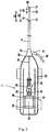
- the device 70 of Figure 6 includes a dual lumen catheter 74.
- the catheter 74 is movable axially with respect to a sheath (not shown) which is identical to sheath 14 of Figure 1 .
- threads 84 function as an Archimedes screw, i.e., a screw pump, to remove the particles/deposits dislodged by the tip 80 extending from one side of rotatable shaft 78 and are positioned proximally of a distal end of the outer sheath. That is, as the shaft 78 is rotated, the screw's helical surface scoops the deposits and directs the deposits proximally (rearwardly) along the shaft 78 within lumen 76 of catheter 74, i.e., in the space between the outer wall of shaft 78 and the wall of lumen 76, to pull dislodged particles proximally.
- an Archimedes screw i.e., a screw pump
- the shaft 78 can have a lumen to receive a guidewire 86 for over the wire insertion of the device 70.
- the rotatable shaft 78 extends through lumen 76 of catheter 74 with the threads 84 directing particles through lumen 76.
- the shaft 78 is attached to the motor and axially fixed in lumen 76 so its distance from the end of catheter 74 remains constant. That is, as in the embodiments described above, the bit 80 remains a fixed distance from the distal edge 82 of catheter 74 in proximal and distal positions of the catheter 74 as the motor housing movement moves both the catheter 74 and rotatable shaft 78 relative to the outer sheath, i.e. sheath 14, in the same manner as the embodiment of Figure 1 .
- Lumen 77 provides for infusion of fluids.
- the atherectomy device 90 of the alternate embodiment of Figure. 7 differs from the embodiment of Figure 6 only in that the rotatable shaft 98 does not have threads and aspiration and fluid infusion can occur in different lumens of the dual lumen catheter 94 than in catheter 74. More specifically, rotatable shaft 98, which has bit 100 extending therefrom, is axially fixed in lumen 96 of catheter 94 and remains a fixed distance from distal catheter edge 95 of catheter 94 in proximal and distal positions of catheter 94, the catheter 94 moved by movement of the motor housing (not shown) in the manner described above.
- Fluid infusion is provided in lumen 96, i.e., in the space between the wall of lumen 96 and the outer wall of shaft 98.
- shaft 98 includes a lumen for over the wire insertion over guidewire 86.
- aspiration of particles is through lumen 97 of catheter 94.
- aspiration of particles may be through lumen 96, i.e., in the space between the wall of lumen 96 and the outer wall of shaft 98, and fluid infusion may be provided through lumen 97 of catheter 94.
- the systems herein can include an aspiration source and/or fluid source.
- Tubing extends from the aspiration source to the catheter and from the fluid source to the catheter.
- An aspiration source can in addition or alternatively communicate with the introducer sheath via a port or side arm to provide aspiration in the space (gap) between the inner wall of the introducer sheath and the outer wall of the sheath.
- the introducer sheath can extend to a region adjacent the tip or alternatively a sleeve could be inserted through the introducer sheath and advanced over the guidewire.
- longitudinal or elongated circular and oval cutting grooves could be provided to provide a roughened surface to cut or ablate the plaque as the tip is rotated.
- the grooves or indentations can be formed by laser cutting a series of grooves extending longitudinally within the interior of the tip stock and ground to remove portions of the outer surface to partially communicate with the grooves, thereby creating indentations forming a roughened surface for contact with the plaque.
- Another way contemplated to create the roughened surface is by blasting, e.g., sandblasting or grit blasting, the tip. The tip is held in a fixture and blasted at a certain pressure, thereby removing portions of the outer surface to create a roughened surface. Creation of a roughened surface by chemical etching is also contemplated or by applying an abrasive coating.
- the atherectomy bit (burr) of the embodiments described herein can be eccentrically or concentrically mounted, and can be of asymmetrical configuration or symmetrical configuration such as oval or elliptical, and can be positioned at the distalmost end of the rotatable shaft or spaced proximally of the distalmost end.
Landscapes
- Health & Medical Sciences (AREA)
- Life Sciences & Earth Sciences (AREA)
- Surgery (AREA)
- Heart & Thoracic Surgery (AREA)
- Engineering & Computer Science (AREA)
- General Health & Medical Sciences (AREA)
- Biomedical Technology (AREA)
- Veterinary Medicine (AREA)
- Public Health (AREA)
- Animal Behavior & Ethology (AREA)
- Vascular Medicine (AREA)
- Nuclear Medicine, Radiotherapy & Molecular Imaging (AREA)
- Medical Informatics (AREA)
- Molecular Biology (AREA)
- Anesthesiology (AREA)
- Hematology (AREA)
- Pulmonology (AREA)
- Surgical Instruments (AREA)
Claims (13)
- Appareil chirurgical d'athérectomie pour éliminer des particules telles que des plaques d'athérome d'un intérieur de vaisseau, l'appareil comprenant : un boîtier externe (12) ; un boîtier de moteur (32) renfermant un moteur ; une gaine fixée axialement (14, 54) s'étendant à partir du boîtier externe ; un cathéter (16, 56, 74) connecté au boîtier de moteur et comportant une lumière (17, 64, 76), le cathéter étant positionné à l'intérieur de la gaine ; et un arbre rotatif (18, 58, 78) positionné à l'intérieur de la lumière du cathéter et connecté fonctionnellement au moteur pour se déplacer en rotation, l'arbre rotatif comportant une pointe d'athérectomie (20, 60, 80) s'étendant à partir de celui-ci pour déloger des particules lors de sa rotation par le moteur ; dans lequel les particules délogées par la pointe d'athérectomie sont aspirées dans la lumière (17, 64, 76) du cathéter (16, 56, 74) dans l'espace entre une paroi externe de l'arbre rotatif (18, 58, 78) et une paroi interne du cathéter, caractérisé en ce que le boîtier de moteur (32) est positionné à l'intérieur du boîtier externe, le boîtier de moteur pouvant coulisser axialement entre une position proximale et une position distale, et en ce que l'arbre rotatif et le cathéter peuvent être déplacés par le déplacement du boîtier de moteur entre les positions proximale et distale ; et en ce que la pointe d'athérectomie (20, 60, 80) s'étend sur une première distance (D1, E1) à partir d'une extrémité distale (23, 82) du cathéter (16, 56, 74) dans la position proximale du boîtier de moteur (32) et s'étend sur la même première distance à partir de l'extrémité distale du cathéter dans la position distale du boîtier de moteur.
- Appareil chirurgical selon la revendication 1, dans lequel les particules sont aspirées par un vide à travers un tube (45) s'étendant à partir d'un orifice de sortie du cathéter (16).
- Appareil chirurgical selon la revendication 1, dans lequel l'arbre rotatif (58, 78) comporte une série de filets de vis (62, 84) positionnée sur celui-ci et formant une région filetée, et les particules sont aspirées par rotation de l'arbre rotatif et des filets de vis.
- Appareil chirurgical selon la revendication 3, dans lequel la région filetée est proximale à une extrémité distale de la gaine (54).
- Appareil chirurgical selon l'une quelconque des revendications précédentes, dans lequel l'extrémité distale (23) du cathéter (16) s'étend sur une deuxième distance (D3) à partir d'une extrémité distale (21, 55) de la gaine (14, 54) dans la position proximale du boîtier de moteur (32) et s'étend sur une troisième distance supérieure (D4) à partir de l'extrémité distale de la gaine dans la position distale du boîtier de moteur.
- Appareil chirurgical selon la revendication 5, dans lequel l'arbre rotatif (58, 78) comporte une région filetée (62, 84) pour diriger les dépôts proximalement lors de la rotation de l'arbre rotatif.
- Appareil chirurgical selon l'une quelconque des revendications précédentes, dans lequel le boîtier externe (12) comporte des premier et second rails (30) positionnés à l'intérieur de celui-ci, et le boîtier de moteur (32) est déplacé le long des rails quand il est déplacé entre les positions rétractée et étendue.
- Appareil chirurgical selon l'une quelconque des revendications précédentes, dans lequel le cathéter (74) comporte des première et seconde lumières (76, 77) et l'arbre rotatif (78) s'étend à travers la première lumière (76).
- Appareil chirurgical selon la revendication 8, dans lequel l'aspiration se fait à travers la première lumière (77) dans un espace entre une paroi externe de l'arbre rotatif (78) et une paroi interne de la première lumière et le fluide est injecté à travers la seconde lumière (77).
- Appareil chirurgical selon l'une quelconque des revendications précédentes, dans lequel la pointe d'athérectomie (20, 60, 80) est positionnée à une extrémité la plus distale de l'arbre (18, 58, 78).
- Appareil chirurgical selon l'une quelconque des revendications précédentes, dans lequel la pointe d'athérectomie (20, 60, 80) comporte un revêtement abrasif pour aider au broyage des particules.
- Appareil chirurgical selon l'une quelconque des revendications précédentes, dans lequel la pointe d'athérectomie (20, 60, 80) est exposée dans les positions rétractée et étendue du cathéter (16, 56, 74).
- Appareil chirurgical selon l'une quelconque des revendications précédentes, dans lequel la pointe d'athérectomie (20, 60, 80) est espacée d'une extrémité la plus distale de l'arbre (18, 58, 78).
Applications Claiming Priority (2)
| Application Number | Priority Date | Filing Date | Title |
|---|---|---|---|
| US201562217963P | 2015-09-13 | 2015-09-13 | |
| US15/242,557 US11253292B2 (en) | 2015-09-13 | 2016-08-21 | Atherectomy device |
Publications (2)
| Publication Number | Publication Date |
|---|---|
| EP3141201A1 EP3141201A1 (fr) | 2017-03-15 |
| EP3141201B1 true EP3141201B1 (fr) | 2021-03-10 |
Family
ID=56883698
Family Applications (1)
| Application Number | Title | Priority Date | Filing Date |
|---|---|---|---|
| EP16187574.5A Active EP3141201B1 (fr) | 2015-09-13 | 2016-09-07 | Dispositif d'athérectomie |
Country Status (2)
| Country | Link |
|---|---|
| US (2) | US11253292B2 (fr) |
| EP (1) | EP3141201B1 (fr) |
Families Citing this family (34)
| Publication number | Priority date | Publication date | Assignee | Title |
|---|---|---|---|---|
| AU2017205323B2 (en) * | 2016-01-04 | 2022-01-27 | Alcyone Therapeutics, Inc. | Methods and devices for treating stroke |
| CN113368367B (zh) | 2016-02-24 | 2024-03-29 | 禾木(中国)生物工程有限公司 | 柔性增强的神经血管导管 |
| CN110381855B (zh) | 2017-01-06 | 2023-07-04 | 因赛普特有限责任公司 | 用于动脉瘤治疗装置的抗血栓涂层 |
| US10413305B2 (en) | 2017-03-21 | 2019-09-17 | Gyrus Acmi, Inc. | Integrated suction and cooling of angled burr |
| US11224458B2 (en) | 2017-04-10 | 2022-01-18 | The Regents Of The University Of Michigan | Hydrodynamic vortex aspiration catheter |
| EP4201346B1 (fr) | 2017-04-10 | 2024-11-06 | The Regents Of The University Of Michigan | Cathéter d'aspiration à vortex hydrodynamique |
| US20180317953A1 (en) | 2017-05-03 | 2018-11-08 | Medtronic Vascular, Inc. | Tissue-removing catheter |
| US11690645B2 (en) | 2017-05-03 | 2023-07-04 | Medtronic Vascular, Inc. | Tissue-removing catheter |
| CN109316224B (zh) * | 2017-08-01 | 2024-02-09 | 上海蓝脉医疗科技有限公司 | 血栓去除装置 |
| US11395665B2 (en) | 2018-05-01 | 2022-07-26 | Incept, Llc | Devices and methods for removing obstructive material, from an intravascular site |
| US11471582B2 (en) | 2018-07-06 | 2022-10-18 | Incept, Llc | Vacuum transfer tool for extendable catheter |
| US11517335B2 (en) | 2018-07-06 | 2022-12-06 | Incept, Llc | Sealed neurovascular extendable catheter |
| US11272954B2 (en) | 2018-08-07 | 2022-03-15 | Cardio Flow, Inc. | Atherectomy devices and methods |
| EP4434477B1 (fr) | 2018-11-16 | 2026-01-14 | Medtronic Vascular Inc. | Cathéter d'ablation de tissu |
| US11766539B2 (en) | 2019-03-29 | 2023-09-26 | Incept, Llc | Enhanced flexibility neurovascular catheter |
| US11819236B2 (en) | 2019-05-17 | 2023-11-21 | Medtronic Vascular, Inc. | Tissue-removing catheter |
| CN110507393B (zh) * | 2019-08-16 | 2024-12-03 | 绍兴市人民医院 | 一种肿瘤套管旋切装置 |
| CN111012448A (zh) * | 2019-08-20 | 2020-04-17 | 上海微创医疗器械(集团)有限公司 | 旋磨装置 |
| US11134859B2 (en) | 2019-10-15 | 2021-10-05 | Imperative Care, Inc. | Systems and methods for multivariate stroke detection |
| US11457947B2 (en) * | 2019-11-06 | 2022-10-04 | C.R. Bard, Inc. | Endovascular translating scoring mechanism utilizing motorized blade |
| US20210315598A1 (en) | 2019-12-18 | 2021-10-14 | Imperative Care, Inc. | Methods of placing large bore aspiration catheters |
| CA3162704A1 (fr) | 2019-12-18 | 2021-06-24 | Imperative Care, Inc. | Methodes et systemes pour le traitement d'une maladie thromboembolique veneuse |
| US11553935B2 (en) | 2019-12-18 | 2023-01-17 | Imperative Care, Inc. | Sterile field clot capture module for use in thrombectomy system |
| US20230248502A1 (en) | 2019-12-18 | 2023-08-10 | Imperative Care, Inc. | Sterile field clot capture module for use in thrombectomy system |
| CA3171899A1 (fr) | 2020-03-10 | 2021-09-16 | Imperative Care, Inc. | Catheter neurovasculaire a flexibilite amelioree |
| US11523841B2 (en) | 2020-09-03 | 2022-12-13 | Cardiovascular Systems, Inc. | Systems, methods and devices for removal of thrombus and/or soft plaque with asymmetric mass distribution within working region of impeller |
| WO2022094166A1 (fr) * | 2020-10-30 | 2022-05-05 | Boston Scientific Scimed, Inc. | Système d'athérectomie |
| CA3210625A1 (fr) | 2021-03-01 | 2022-09-09 | Scott J. Baron | Dispositifs d'aspiration pour le traitement de la thrombose comprenant des extremites distales expansibles et systemes et methodes associees |
| US11696793B2 (en) | 2021-03-19 | 2023-07-11 | Crossfire Medical Inc | Vascular ablation |
| US20230048388A1 (en) | 2021-08-12 | 2023-02-16 | Imperative Care, Inc. | Robotically driven interventional device |
| USD1077996S1 (en) | 2021-10-18 | 2025-06-03 | Imperative Care, Inc. | Inline fluid filter |
| US12053192B2 (en) | 2022-09-01 | 2024-08-06 | Endovascular Engineering, Inc. | Systems, devices, and methods for aspiration, including expandable structures and rotatable shafts |
| CN115444515A (zh) * | 2022-09-14 | 2022-12-09 | 中国医科大学附属第一医院 | 一种血管内旋磨装置 |
| US12171917B1 (en) | 2024-01-08 | 2024-12-24 | Imperative Care, Inc. | Devices for blood capture and reintroduction during aspiration procedure |
Family Cites Families (142)
| Publication number | Priority date | Publication date | Assignee | Title |
|---|---|---|---|---|
| US4445509A (en) * | 1982-02-04 | 1984-05-01 | Auth David C | Method and apparatus for removal of enclosed abnormal deposits |
| US4979939A (en) | 1984-05-14 | 1990-12-25 | Surgical Systems & Instruments, Inc. | Atherectomy system with a guide wire |
| US5306244A (en) | 1984-05-14 | 1994-04-26 | Surgical Systems & Instruments, Inc. | Method of guidewire insertion |
| US4957482A (en) | 1988-12-19 | 1990-09-18 | Surgical Systems & Instruments, Inc. | Atherectomy device with a positive pump means |
| US4883458A (en) | 1987-02-24 | 1989-11-28 | Surgical Systems & Instruments, Inc. | Atherectomy system and method of using the same |
| US5653696A (en) | 1984-05-14 | 1997-08-05 | Surgical Systems & Instruments, Inc. | Stent unclogging method |
| CA1293663C (fr) | 1986-01-06 | 1991-12-31 | David Christopher Auth | Appareil de micro-dissection intravasculaire |
| US5047040A (en) | 1987-11-05 | 1991-09-10 | Devices For Vascular Intervention, Inc. | Atherectomy device and method |
| US5431673A (en) * | 1989-02-17 | 1995-07-11 | American Biomed, Inc. | Distal atherectomy catheter |
| US5728129A (en) * | 1989-02-17 | 1998-03-17 | American Biomed, Inc. | Distal atherectomy catheter |
| US5019089A (en) | 1989-12-07 | 1991-05-28 | Interventional Technologies Inc. | Atherectomy advancing probe and method of use |
| US5114399A (en) | 1990-10-01 | 1992-05-19 | Intramed Laboratories | Surgical device |
| US5273526A (en) | 1991-06-21 | 1993-12-28 | Lake Region Manufacturing Company, Inc. | Vascular occulusion removal devices and method |
| US5217474A (en) | 1991-07-15 | 1993-06-08 | Zacca Nadim M | Expandable tip atherectomy method and apparatus |
| US6623516B2 (en) | 1992-08-13 | 2003-09-23 | Mark A. Saab | Method for changing the temperature of a selected body region |
| US5287858A (en) | 1992-09-23 | 1994-02-22 | Pilot Cardiovascular Systems, Inc. | Rotational atherectomy guidewire |
| CA2107741C (fr) | 1992-10-07 | 2000-06-27 | Peter T. Keith | Dispositifs d'ablation et methodes d'utilisation |
| US5356418A (en) * | 1992-10-28 | 1994-10-18 | Shturman Cardiology Systems, Inc. | Apparatus and method for rotational atherectomy |
| US5312427A (en) * | 1992-10-16 | 1994-05-17 | Shturman Cardiology Systems, Inc. | Device and method for directional rotational atherectomy |
| US5360432A (en) * | 1992-10-16 | 1994-11-01 | Shturman Cardiology Systems, Inc. | Abrasive drive shaft device for directional rotational atherectomy |
| US5643297A (en) | 1992-11-09 | 1997-07-01 | Endovascular Instruments, Inc. | Intra-artery obstruction clearing apparatus and methods |
| US5490859A (en) | 1992-11-13 | 1996-02-13 | Scimed Life Systems, Inc. | Expandable intravascular occlusion material removal devices and methods of use |
| US5794626A (en) | 1994-08-18 | 1998-08-18 | Kieturakis; Maciej J. | Excisional stereotactic apparatus |
| US5584843A (en) | 1994-12-20 | 1996-12-17 | Boston Scientific Corporation | Shaped wire multi-burr rotational ablation device |
| DE59609303D1 (de) | 1995-03-28 | 2002-07-11 | Straub Medical Ag | Katheter zum ablösen von abnormalen ablagerungen in menschlichen blutgefässen |
| EP0817595B1 (fr) | 1995-03-28 | 2002-06-12 | Straub Medical AG | Catheter permettant de detacher des depots anormaux situes dans des vaisseaux sanguins chez l'homme |
| US5681336A (en) | 1995-09-07 | 1997-10-28 | Boston Scientific Corporation | Therapeutic device for treating vien graft lesions |
| US6080170A (en) | 1996-07-26 | 2000-06-27 | Kensey Nash Corporation | System and method of use for revascularizing stenotic bypass grafts and other occluded blood vessels |
| US6652546B1 (en) | 1996-07-26 | 2003-11-25 | Kensey Nash Corporation | System and method of use for revascularizing stenotic bypass grafts and other occluded blood vessels |
| US6830577B2 (en) | 1996-07-26 | 2004-12-14 | Kensey Nash Corporation | System and method of use for treating occluded vessels and diseased tissue |
| US6569147B1 (en) | 1996-07-26 | 2003-05-27 | Kensey Nash Corporation | Systems and methods of use for delivering beneficial agents for revascularizing stenotic bypass grafts and other occluded blood vessels and for other purposes |
| US5779721A (en) | 1996-07-26 | 1998-07-14 | Kensey Nash Corporation | System and method of use for revascularizing stenotic bypass grafts and other blood vessels |
| US6905505B2 (en) | 1996-07-26 | 2005-06-14 | Kensey Nash Corporation | System and method of use for agent delivery and revascularizing of grafts and vessels |
| US5899915A (en) | 1996-12-02 | 1999-05-04 | Angiotrax, Inc. | Apparatus and method for intraoperatively performing surgery |
| US6015420A (en) | 1997-03-06 | 2000-01-18 | Scimed Life Systems, Inc. | Atherectomy device for reducing damage to vessels and/or in-vivo stents |
| US6183487B1 (en) | 1997-03-06 | 2001-02-06 | Scimed Life Systems, Inc. | Ablation device for reducing damage to vessels and/or in-vivo stents |
| US7037316B2 (en) | 1997-07-24 | 2006-05-02 | Mcguckin Jr James F | Rotational thrombectomy device |
| US6090118A (en) | 1998-07-23 | 2000-07-18 | Mcguckin, Jr.; James F. | Rotational thrombectomy apparatus and method with standing wave |
| US6132444A (en) | 1997-08-14 | 2000-10-17 | Shturman Cardiology Systems, Inc. | Eccentric drive shaft for atherectomy device and method for manufacture |
| US6494890B1 (en) | 1997-08-14 | 2002-12-17 | Shturman Cardiology Systems, Inc. | Eccentric rotational atherectomy device |
| US6077282A (en) | 1997-10-27 | 2000-06-20 | Shturman Cardiology Systems, Inc. | Rotational atherectomy device with exchangeable drive shaft cartridge |
| US6156046A (en) | 1997-11-07 | 2000-12-05 | Prolifix Medical, Inc. | Methods and systems for treating obstructions in a body lumen |
| US5976165A (en) | 1997-12-10 | 1999-11-02 | Scimed Life Systems, Inc. | Rotational ablation device having replaceable screw-on burrs |
| US6824550B1 (en) | 2000-04-06 | 2004-11-30 | Norbon Medical, Inc. | Guidewire for crossing occlusions or stenosis |
| US6096054A (en) | 1998-03-05 | 2000-08-01 | Scimed Life Systems, Inc. | Expandable atherectomy burr and method of ablating an occlusion from a patient's blood vessel |
| US6146395A (en) | 1998-03-05 | 2000-11-14 | Scimed Life Systems, Inc. | Ablation burr |
| US6666874B2 (en) | 1998-04-10 | 2003-12-23 | Endicor Medical, Inc. | Rotational atherectomy system with serrated cutting tip |
| US6001112A (en) | 1998-04-10 | 1999-12-14 | Endicor Medical, Inc. | Rotational atherectomy device |
| US6482217B1 (en) | 1998-04-10 | 2002-11-19 | Endicor Medical, Inc. | Neuro thrombectomy catheter |
| CA2256132A1 (fr) | 1998-12-16 | 2000-06-16 | Brian M. Strauss | Mecanisme d'accessoire rotatif pour relier un sous-ensemble dispositif de traitement des obstructions medicales a un moteur d'entrainement |
| US6113615A (en) | 1999-02-03 | 2000-09-05 | Scimed Life Systems, Inc. | Atherectomy burr including a bias wire |
| US20030125757A1 (en) | 2000-12-20 | 2003-07-03 | Fox Hollow Technologies, Inc. | Debulking catheters and methods |
| US7655016B2 (en) | 1999-09-17 | 2010-02-02 | Covidien | Mechanical pump for removal of fragmented matter and methods of manufacture and use |
| EP1225949B1 (fr) | 1999-09-17 | 2012-11-07 | Tyco Healthcare Group LP | Pompe mecanique pour retrait de matiere fragmentee |
| US6702830B1 (en) | 1999-09-17 | 2004-03-09 | Bacchus Vascular, Inc. | Mechanical pump for removal of fragmented matter and methods of manufacture and use |
| US8414543B2 (en) | 1999-10-22 | 2013-04-09 | Rex Medical, L.P. | Rotational thrombectomy wire with blocking device |
| AU2614901A (en) | 1999-10-22 | 2001-04-30 | Boston Scientific Corporation | Double balloon thrombectomy catheter |
| US6579299B2 (en) | 2000-01-31 | 2003-06-17 | Rex Medical, L.P. | Atherectomy device |
| US6572630B1 (en) | 2000-01-31 | 2003-06-03 | Rex Medical, L.P | Atherectomy device |
| US6579298B1 (en) * | 2000-02-29 | 2003-06-17 | Scimed Life Systems, Inc. | Method and apparatus for treating vein graft lesions |
| EP1267989B1 (fr) * | 2000-04-05 | 2006-07-19 | Pathway Medical Technologies, Inc. | Systemes et procedes de retrait de matiere intraluminale |
| US20040243162A1 (en) | 2000-04-05 | 2004-12-02 | Pathway Medical Technologies, Inc. | Interventional catheter assemblies and control systems |
| US6565588B1 (en) | 2000-04-05 | 2003-05-20 | Pathway Medical Technologies, Inc. | Intralumenal material removal using an expandable cutting device |
| US8475484B2 (en) | 2000-04-05 | 2013-07-02 | Medrad, Inc. | Liquid seal assembly for a rotating torque tube |
| US7344546B2 (en) | 2000-04-05 | 2008-03-18 | Pathway Medical Technologies | Intralumenal material removal using a cutting device for differential cutting |
| US6676698B2 (en) | 2000-06-26 | 2004-01-13 | Rex Medicol, L.P. | Vascular device with valve for approximating vessel wall |
| US6497711B1 (en) | 2000-08-16 | 2002-12-24 | Scimed Life Systems, Inc. | Therectomy device having a light weight drive shaft and an imaging device |
| AU2000277330A1 (en) | 2000-09-28 | 2002-04-08 | Robert C Beck | Catheter system |
| US6569177B1 (en) | 2001-01-19 | 2003-05-27 | Scimed Life Systems, Inc. | Ablation atherectomy burr |
| US6491660B2 (en) | 2001-01-23 | 2002-12-10 | Scimed Life Systems, Inc. | Frontal infusion system for intravenous burrs |
| US6632230B2 (en) | 2001-04-12 | 2003-10-14 | Scimed Life Systems, Inc. | Ablation system with catheter clearing abrasive |
| US6500186B2 (en) | 2001-04-17 | 2002-12-31 | Scimed Life Systems, Inc. | In-stent ablative tool |
| US6443967B1 (en) | 2001-05-03 | 2002-09-03 | Scimed Life Systems, Inc. | Injection moldable feedstock including diamond particles for abrasive applications |
| US6626890B2 (en) | 2001-06-06 | 2003-09-30 | Tony R. Brown | Fat removal device and method |
| US6926725B2 (en) | 2002-04-04 | 2005-08-09 | Rex Medical, L.P. | Thrombectomy device with multi-layered rotational wire |
| US6752630B2 (en) | 2002-04-09 | 2004-06-22 | Patrick L. Roetzer | Dental retractor and fluid control system |
| WO2005030063A1 (fr) * | 2003-09-26 | 2005-04-07 | Johnson And Johnson Kabushiki Kaisha | Instrument de traitement medical |
| US8876882B2 (en) | 2003-10-10 | 2014-11-04 | Mark Gelido Barongan | Cutting stent |
| US7799043B2 (en) | 2003-12-01 | 2010-09-21 | Boston Scientific Scimed, Inc. | Cutting balloon having sheathed incising elements |
| EP1722694B1 (fr) | 2004-03-04 | 2009-05-20 | Straub Medical AG | Catheter concu pour aspirer, fragmenter et evacuer de la matiere extractible de vaisseaux sanguins |
| US7959608B2 (en) | 2004-04-27 | 2011-06-14 | The Spectranetics Corporation | Thrombectomy and soft debris removal device |
| US8920402B2 (en) | 2004-04-27 | 2014-12-30 | The Spectranetics Corporation | Thrombectomy and soft debris removal device |
| US7819887B2 (en) | 2004-11-17 | 2010-10-26 | Rex Medical, L.P. | Rotational thrombectomy wire |
| GB2426458A (en) | 2005-05-26 | 2006-11-29 | Leonid Shturman | Atherectomy device |
| GB2426456B (en) | 2005-05-26 | 2010-10-27 | Leonid Shturman | Rotational device with eccentric abrasive element and method of use |
| US20070162062A1 (en) * | 2005-12-08 | 2007-07-12 | Norton Britt K | Reciprocating apparatus and methods for removal of intervertebral disc tissues |
| US8007506B2 (en) | 2006-06-30 | 2011-08-30 | Atheromed, Inc. | Atherectomy devices and methods |
| US9492192B2 (en) | 2006-06-30 | 2016-11-15 | Atheromed, Inc. | Atherectomy devices, systems, and methods |
| US8361094B2 (en) | 2006-06-30 | 2013-01-29 | Atheromed, Inc. | Atherectomy devices and methods |
| US7981128B2 (en) | 2006-06-30 | 2011-07-19 | Atheromed, Inc. | Atherectomy devices and methods |
| US20080045986A1 (en) | 2006-06-30 | 2008-02-21 | Atheromed, Inc. | Atherectomy devices and methods |
| US8628549B2 (en) * | 2006-06-30 | 2014-01-14 | Atheromed, Inc. | Atherectomy devices, systems, and methods |
| GB0613981D0 (fr) | 2006-07-13 | 2006-08-23 | Shturman Leonid | |
| CA2677343C (fr) | 2007-02-05 | 2016-06-21 | Boston Scientific Limited | Appareil et procede de thrombectomie |
| NL1034242C2 (nl) | 2007-02-16 | 2008-08-19 | T M H Beheer B V | Katheter, kathetersysteem en werkwijze voor het intervenieren in een kanaal-vormig orgaan, zoals een bloedbaan. |
| US8597313B2 (en) | 2007-06-11 | 2013-12-03 | Cardiovascular Systems, Inc. | Eccentric abrading head for high-speed rotational atherectomy devices |
| EP2160137A2 (fr) | 2007-06-21 | 2010-03-10 | Ariomedica Ltd. | Configuration d'infusion et de succion dans un système d'athérectomie |
| US8439937B2 (en) | 2007-06-25 | 2013-05-14 | Cardiovascular Systems, Inc. | System, apparatus and method for opening an occluded lesion |
| US8236016B2 (en) | 2007-10-22 | 2012-08-07 | Atheromed, Inc. | Atherectomy devices and methods |
| US8348965B2 (en) | 2007-10-23 | 2013-01-08 | Cardiovascular Systems, Inc. | Rotational atherectomy device with counterweighting |
| US8551128B2 (en) | 2007-12-06 | 2013-10-08 | Cardiovascular Systems, Inc. | Rotational atherectomy device with pre-curved drive shaft |
| US8579851B2 (en) | 2007-12-20 | 2013-11-12 | Bausch & Lomb Incorporated | Surgical system having means for isolating vacuum pump |
| US8062316B2 (en) | 2008-04-23 | 2011-11-22 | Avinger, Inc. | Catheter system and method for boring through blocked vascular passages |
| US8702735B2 (en) | 2008-05-30 | 2014-04-22 | Cardiovascular Systems, Inc. | Eccentric abrading element for high-speed rotational atherectomy devices |
| US9055966B2 (en) | 2008-05-30 | 2015-06-16 | Cardiovascular Systems, Inc. | Eccentric abrading and cutting head for high-speed rotational atherectomy devices |
| US8758377B2 (en) | 2008-05-30 | 2014-06-24 | Cardiovascular Systems, Inc. | Eccentric abrading and cutting head for high-speed rotational atherectomy devices |
| CH699981A2 (de) | 2008-11-27 | 2010-05-31 | Straub Medical Ag | Katheter zum Ansaugen, Fragmentieren und Hinausbefördern von entfernbarem Material aus Blutgefässen. |
| US8795303B2 (en) | 2009-02-02 | 2014-08-05 | Cardiovascular Systems, Inc. | Multi-material abrading head for atherectomy devices having laterally displaced center of mass |
| US8628550B2 (en) | 2009-02-19 | 2014-01-14 | Cardiovascular Systems, Inc. | Rotational atherectomy segmented abrading head and method to improve abrading efficiency |
| GB0905751D0 (en) | 2009-04-03 | 2009-05-20 | Shturman Leonid | Rotational atherectomy device with distal embolic protection and method of use |
| US8632557B2 (en) | 2009-05-12 | 2014-01-21 | Cardiovascular Systems, Inc. | Rotational atherectomy device and method to improve abrading efficiency |
| JP5281195B2 (ja) | 2009-05-14 | 2013-09-04 | コヴィディエン リミテッド パートナーシップ | 簡単に清掃され得るアテレクトミー用カテーテルおよび使用の方法 |
| US8795304B2 (en) | 2009-06-18 | 2014-08-05 | Cardiovascular Systems, Inc. | Atherectomy device, system and method having a bi-directional distal expandable ablation element |
| US8388582B2 (en) | 2009-08-12 | 2013-03-05 | Medrad, Inc. | Systems and methods for operating interventional catheters using a common operating console and adaptive interface components |
| US9050126B2 (en) | 2010-02-26 | 2015-06-09 | Cardiovascular Systems, Inc. | Rotational atherectomy device with electric motor |
| US8273097B2 (en) | 2010-04-30 | 2012-09-25 | Medtronic Xomed, Inc. | Powered surgical tissue cutting instrument having an irrigation system |
| WO2011139460A1 (fr) | 2010-05-04 | 2011-11-10 | Samuel Shiber | Cathéter rotatif pour enlever des obstructions de vaisseaux corporels |
| US9023070B2 (en) | 2010-05-13 | 2015-05-05 | Rex Medical, L.P. | Rotational thrombectomy wire coupler |
| US8663259B2 (en) | 2010-05-13 | 2014-03-04 | Rex Medical L.P. | Rotational thrombectomy wire |
| US8764779B2 (en) | 2010-05-13 | 2014-07-01 | Rex Medical, L.P. | Rotational thrombectomy wire |
| EP2640288A4 (fr) | 2010-11-15 | 2014-08-27 | Spine View Inc | Système d'enlèvement de tissu doté d'un mécanisme de retenue |
| US9585667B2 (en) | 2010-11-15 | 2017-03-07 | Vascular Insights Llc | Sclerotherapy catheter with lumen having wire rotated by motor and simultaneous withdrawal from vein |
| JP2014506167A (ja) | 2010-12-20 | 2014-03-13 | スパイン ビュー, インコーポレイテッド | 関節運動組織除去システムおよび方法 |
| US20120211542A1 (en) | 2011-02-23 | 2012-08-23 | Tyco Healthcare Group I.P | Controlled tissue compression systems and methods |
| US9700347B2 (en) | 2011-08-17 | 2017-07-11 | Samuel Shiber | Adaptive rotary catheter for opening obstructed bodily vessels |
| WO2013056262A1 (fr) | 2011-10-13 | 2013-04-18 | Atheromed, Inc. | Appareil, systèmes et procédés d'athérectomie |
| US9028424B2 (en) | 2011-12-02 | 2015-05-12 | Interscope, Inc. | Endoscope including a torque generation component or torque delivery component disposed within an insertable portion of the endoscope and a surgical cutting assembly insertable within the endoscope |
| US9033864B2 (en) | 2011-12-02 | 2015-05-19 | Interscope, Inc. | Endoscope including a torque generation component or torque delivery component disposed within an insertable portion of the endoscope and a surgical cutting assembly insertable within the endoscope |
| US8882680B2 (en) | 2011-12-02 | 2014-11-11 | Interscope, Inc. | Insertable endoscopic instrument for tissue removal |
| US9033895B2 (en) | 2011-12-02 | 2015-05-19 | Interscope, Inc. | Endoscope including an torque generation component or torque delivery component disposed within an insertable portion of the endoscope and a surgical cutting assembly insertable within the endoscope |
| KR20130080909A (ko) | 2012-01-06 | 2013-07-16 | 삼성전자주식회사 | 수술 로봇 및 그 제어 방법 |
| EP2825105B1 (fr) | 2012-03-13 | 2022-05-04 | Medtronic Xomed, Inc. | Système chirurgical comprenant une pièce à main électrique de type rotatif |
| US20130253552A1 (en) | 2012-03-20 | 2013-09-26 | Cardiovascular Systems, Inc. | Controller for an atherectomy device |
| CN102670283A (zh) | 2012-06-08 | 2012-09-19 | 李广成 | 血肿清除器的碎吸器 |
| US9539022B2 (en) | 2012-11-28 | 2017-01-10 | Microvention, Inc. | Matter conveyance system |
| JP6391910B2 (ja) | 2012-12-14 | 2018-09-19 | 株式会社グッドマン | 吸引カテーテル |
| EP3260067B1 (fr) | 2013-03-12 | 2019-12-04 | Boston Scientific Scimed, Inc. | Athérectomie améliorée par vibration et inertie |
| US9848907B2 (en) | 2013-03-15 | 2017-12-26 | Cardiovascular Systems, Inc. | Rotational atherectomy device with biasing clutch |
| US20140330286A1 (en) | 2013-04-25 | 2014-11-06 | Michael P. Wallace | Methods and Devices for Removing Obstructing Material From the Human Body |
| US10271869B2 (en) | 2014-03-01 | 2019-04-30 | Rex Medical, L.P. | Atherectomy device |
| US10405924B2 (en) | 2014-05-30 | 2019-09-10 | The Spectranetics Corporation | System and method of ablative cutting and vacuum aspiration through primary orifice and auxiliary side port |
| US10307175B2 (en) | 2016-03-26 | 2019-06-04 | Rex Medical, L.P | Atherectomy device |
-
2016
- 2016-08-21 US US15/242,557 patent/US11253292B2/en active Active
- 2016-09-07 EP EP16187574.5A patent/EP3141201B1/fr active Active
-
2022
- 2022-02-11 US US17/669,444 patent/US12274822B2/en active Active
Non-Patent Citations (1)
| Title |
|---|
| None * |
Also Published As
| Publication number | Publication date |
|---|---|
| US12274822B2 (en) | 2025-04-15 |
| US11253292B2 (en) | 2022-02-22 |
| US20170071624A1 (en) | 2017-03-16 |
| EP3141201A1 (fr) | 2017-03-15 |
| US20220202441A1 (en) | 2022-06-30 |
Similar Documents
| Publication | Publication Date | Title |
|---|---|---|
| US12274822B2 (en) | Atherectomy device | |
| US10751083B2 (en) | Atherectomy device | |
| US12478392B2 (en) | Atherectomy device | |
| US20230270463A1 (en) | Atherectomy device | |
| US20220401122A1 (en) | Atherectomy device | |
| US6579299B2 (en) | Atherectomy device | |
| US10357275B2 (en) | Dual-basket self-centering rotational device for treatment of arterial occlusive disease with infinitely adjustable cutting size | |
| EP3037050B1 (fr) | Dispositif d'athérectomie | |
| US12458393B2 (en) | Rotary debulking atherectomy device with a crossing balloon | |
| EP3871619B1 (fr) | Dispositif de coupe-blocage réglable |
Legal Events
| Date | Code | Title | Description |
|---|---|---|---|
| PUAI | Public reference made under article 153(3) epc to a published international application that has entered the european phase |
Free format text: ORIGINAL CODE: 0009012 |
|
| STAA | Information on the status of an ep patent application or granted ep patent |
Free format text: STATUS: THE APPLICATION HAS BEEN PUBLISHED |
|
| AK | Designated contracting states |
Kind code of ref document: A1 Designated state(s): AL AT BE BG CH CY CZ DE DK EE ES FI FR GB GR HR HU IE IS IT LI LT LU LV MC MK MT NL NO PL PT RO RS SE SI SK SM TR |
|
| AX | Request for extension of the european patent |
Extension state: BA ME |
|
| STAA | Information on the status of an ep patent application or granted ep patent |
Free format text: STATUS: REQUEST FOR EXAMINATION WAS MADE |
|
| 17P | Request for examination filed |
Effective date: 20170913 |
|
| RBV | Designated contracting states (corrected) |
Designated state(s): AL AT BE BG CH CY CZ DE DK EE ES FI FR GB GR HR HU IE IS IT LI LT LU LV MC MK MT NL NO PL PT RO RS SE SI SK SM TR |
|
| GRAP | Despatch of communication of intention to grant a patent |
Free format text: ORIGINAL CODE: EPIDOSNIGR1 |
|
| STAA | Information on the status of an ep patent application or granted ep patent |
Free format text: STATUS: GRANT OF PATENT IS INTENDED |
|
| INTG | Intention to grant announced |
Effective date: 20201005 |
|
| GRAS | Grant fee paid |
Free format text: ORIGINAL CODE: EPIDOSNIGR3 |
|
| GRAA | (expected) grant |
Free format text: ORIGINAL CODE: 0009210 |
|
| STAA | Information on the status of an ep patent application or granted ep patent |
Free format text: STATUS: THE PATENT HAS BEEN GRANTED |
|
| AK | Designated contracting states |
Kind code of ref document: B1 Designated state(s): AL AT BE BG CH CY CZ DE DK EE ES FI FR GB GR HR HU IE IS IT LI LT LU LV MC MK MT NL NO PL PT RO RS SE SI SK SM TR |
|
| REG | Reference to a national code |
Ref country code: GB Ref legal event code: FG4D |
|
| REG | Reference to a national code |
Ref country code: AT Ref legal event code: REF Ref document number: 1368922 Country of ref document: AT Kind code of ref document: T Effective date: 20210315 Ref country code: CH Ref legal event code: EP |
|
| REG | Reference to a national code |
Ref country code: DE Ref legal event code: R096 Ref document number: 602016053916 Country of ref document: DE |
|
| REG | Reference to a national code |
Ref country code: IE Ref legal event code: FG4D |
|
| REG | Reference to a national code |
Ref country code: LT Ref legal event code: MG9D |
|
| PG25 | Lapsed in a contracting state [announced via postgrant information from national office to epo] |
Ref country code: BG Free format text: LAPSE BECAUSE OF FAILURE TO SUBMIT A TRANSLATION OF THE DESCRIPTION OR TO PAY THE FEE WITHIN THE PRESCRIBED TIME-LIMIT Effective date: 20210610 Ref country code: GR Free format text: LAPSE BECAUSE OF FAILURE TO SUBMIT A TRANSLATION OF THE DESCRIPTION OR TO PAY THE FEE WITHIN THE PRESCRIBED TIME-LIMIT Effective date: 20210611 Ref country code: FI Free format text: LAPSE BECAUSE OF FAILURE TO SUBMIT A TRANSLATION OF THE DESCRIPTION OR TO PAY THE FEE WITHIN THE PRESCRIBED TIME-LIMIT Effective date: 20210310 Ref country code: HR Free format text: LAPSE BECAUSE OF FAILURE TO SUBMIT A TRANSLATION OF THE DESCRIPTION OR TO PAY THE FEE WITHIN THE PRESCRIBED TIME-LIMIT Effective date: 20210310 Ref country code: LT Free format text: LAPSE BECAUSE OF FAILURE TO SUBMIT A TRANSLATION OF THE DESCRIPTION OR TO PAY THE FEE WITHIN THE PRESCRIBED TIME-LIMIT Effective date: 20210310 Ref country code: NO Free format text: LAPSE BECAUSE OF FAILURE TO SUBMIT A TRANSLATION OF THE DESCRIPTION OR TO PAY THE FEE WITHIN THE PRESCRIBED TIME-LIMIT Effective date: 20210610 |
|
| REG | Reference to a national code |
Ref country code: AT Ref legal event code: MK05 Ref document number: 1368922 Country of ref document: AT Kind code of ref document: T Effective date: 20210310 |
|
| REG | Reference to a national code |
Ref country code: NL Ref legal event code: MP Effective date: 20210310 |
|
| PG25 | Lapsed in a contracting state [announced via postgrant information from national office to epo] |
Ref country code: RS Free format text: LAPSE BECAUSE OF FAILURE TO SUBMIT A TRANSLATION OF THE DESCRIPTION OR TO PAY THE FEE WITHIN THE PRESCRIBED TIME-LIMIT Effective date: 20210310 Ref country code: LV Free format text: LAPSE BECAUSE OF FAILURE TO SUBMIT A TRANSLATION OF THE DESCRIPTION OR TO PAY THE FEE WITHIN THE PRESCRIBED TIME-LIMIT Effective date: 20210310 Ref country code: SE Free format text: LAPSE BECAUSE OF FAILURE TO SUBMIT A TRANSLATION OF THE DESCRIPTION OR TO PAY THE FEE WITHIN THE PRESCRIBED TIME-LIMIT Effective date: 20210310 |
|
| PG25 | Lapsed in a contracting state [announced via postgrant information from national office to epo] |
Ref country code: NL Free format text: LAPSE BECAUSE OF FAILURE TO SUBMIT A TRANSLATION OF THE DESCRIPTION OR TO PAY THE FEE WITHIN THE PRESCRIBED TIME-LIMIT Effective date: 20210310 |
|
| PG25 | Lapsed in a contracting state [announced via postgrant information from national office to epo] |
Ref country code: CZ Free format text: LAPSE BECAUSE OF FAILURE TO SUBMIT A TRANSLATION OF THE DESCRIPTION OR TO PAY THE FEE WITHIN THE PRESCRIBED TIME-LIMIT Effective date: 20210310 Ref country code: EE Free format text: LAPSE BECAUSE OF FAILURE TO SUBMIT A TRANSLATION OF THE DESCRIPTION OR TO PAY THE FEE WITHIN THE PRESCRIBED TIME-LIMIT Effective date: 20210310 Ref country code: AT Free format text: LAPSE BECAUSE OF FAILURE TO SUBMIT A TRANSLATION OF THE DESCRIPTION OR TO PAY THE FEE WITHIN THE PRESCRIBED TIME-LIMIT Effective date: 20210310 Ref country code: SM Free format text: LAPSE BECAUSE OF FAILURE TO SUBMIT A TRANSLATION OF THE DESCRIPTION OR TO PAY THE FEE WITHIN THE PRESCRIBED TIME-LIMIT Effective date: 20210310 |
|
| PG25 | Lapsed in a contracting state [announced via postgrant information from national office to epo] |
Ref country code: PL Free format text: LAPSE BECAUSE OF FAILURE TO SUBMIT A TRANSLATION OF THE DESCRIPTION OR TO PAY THE FEE WITHIN THE PRESCRIBED TIME-LIMIT Effective date: 20210310 Ref country code: PT Free format text: LAPSE BECAUSE OF FAILURE TO SUBMIT A TRANSLATION OF THE DESCRIPTION OR TO PAY THE FEE WITHIN THE PRESCRIBED TIME-LIMIT Effective date: 20210712 Ref country code: ES Free format text: LAPSE BECAUSE OF FAILURE TO SUBMIT A TRANSLATION OF THE DESCRIPTION OR TO PAY THE FEE WITHIN THE PRESCRIBED TIME-LIMIT Effective date: 20210310 Ref country code: SK Free format text: LAPSE BECAUSE OF FAILURE TO SUBMIT A TRANSLATION OF THE DESCRIPTION OR TO PAY THE FEE WITHIN THE PRESCRIBED TIME-LIMIT Effective date: 20210310 Ref country code: RO Free format text: LAPSE BECAUSE OF FAILURE TO SUBMIT A TRANSLATION OF THE DESCRIPTION OR TO PAY THE FEE WITHIN THE PRESCRIBED TIME-LIMIT Effective date: 20210310 Ref country code: IS Free format text: LAPSE BECAUSE OF FAILURE TO SUBMIT A TRANSLATION OF THE DESCRIPTION OR TO PAY THE FEE WITHIN THE PRESCRIBED TIME-LIMIT Effective date: 20210710 |
|
| REG | Reference to a national code |
Ref country code: DE Ref legal event code: R097 Ref document number: 602016053916 Country of ref document: DE |
|
| PLBE | No opposition filed within time limit |
Free format text: ORIGINAL CODE: 0009261 |
|
| STAA | Information on the status of an ep patent application or granted ep patent |
Free format text: STATUS: NO OPPOSITION FILED WITHIN TIME LIMIT |
|
| PG25 | Lapsed in a contracting state [announced via postgrant information from national office to epo] |
Ref country code: DK Free format text: LAPSE BECAUSE OF FAILURE TO SUBMIT A TRANSLATION OF THE DESCRIPTION OR TO PAY THE FEE WITHIN THE PRESCRIBED TIME-LIMIT Effective date: 20210310 Ref country code: AL Free format text: LAPSE BECAUSE OF FAILURE TO SUBMIT A TRANSLATION OF THE DESCRIPTION OR TO PAY THE FEE WITHIN THE PRESCRIBED TIME-LIMIT Effective date: 20210310 |
|
| 26N | No opposition filed |
Effective date: 20211213 |
|
| PG25 | Lapsed in a contracting state [announced via postgrant information from national office to epo] |
Ref country code: SI Free format text: LAPSE BECAUSE OF FAILURE TO SUBMIT A TRANSLATION OF THE DESCRIPTION OR TO PAY THE FEE WITHIN THE PRESCRIBED TIME-LIMIT Effective date: 20210310 |
|
| PG25 | Lapsed in a contracting state [announced via postgrant information from national office to epo] |
Ref country code: IT Free format text: LAPSE BECAUSE OF FAILURE TO SUBMIT A TRANSLATION OF THE DESCRIPTION OR TO PAY THE FEE WITHIN THE PRESCRIBED TIME-LIMIT Effective date: 20210310 |
|
| REG | Reference to a national code |
Ref country code: CH Ref legal event code: PL |
|
| REG | Reference to a national code |
Ref country code: BE Ref legal event code: MM Effective date: 20210930 |
|
| PG25 | Lapsed in a contracting state [announced via postgrant information from national office to epo] |
Ref country code: IS Free format text: LAPSE BECAUSE OF FAILURE TO SUBMIT A TRANSLATION OF THE DESCRIPTION OR TO PAY THE FEE WITHIN THE PRESCRIBED TIME-LIMIT Effective date: 20210710 Ref country code: MC Free format text: LAPSE BECAUSE OF FAILURE TO SUBMIT A TRANSLATION OF THE DESCRIPTION OR TO PAY THE FEE WITHIN THE PRESCRIBED TIME-LIMIT Effective date: 20210310 |
|
| PG25 | Lapsed in a contracting state [announced via postgrant information from national office to epo] |
Ref country code: LU Free format text: LAPSE BECAUSE OF NON-PAYMENT OF DUE FEES Effective date: 20210907 Ref country code: IE Free format text: LAPSE BECAUSE OF NON-PAYMENT OF DUE FEES Effective date: 20210907 Ref country code: BE Free format text: LAPSE BECAUSE OF NON-PAYMENT OF DUE FEES Effective date: 20210930 |
|
| PG25 | Lapsed in a contracting state [announced via postgrant information from national office to epo] |
Ref country code: LI Free format text: LAPSE BECAUSE OF NON-PAYMENT OF DUE FEES Effective date: 20210930 Ref country code: CH Free format text: LAPSE BECAUSE OF NON-PAYMENT OF DUE FEES Effective date: 20210930 |
|
| PG25 | Lapsed in a contracting state [announced via postgrant information from national office to epo] |
Ref country code: HU Free format text: LAPSE BECAUSE OF FAILURE TO SUBMIT A TRANSLATION OF THE DESCRIPTION OR TO PAY THE FEE WITHIN THE PRESCRIBED TIME-LIMIT; INVALID AB INITIO Effective date: 20160907 |
|
| PG25 | Lapsed in a contracting state [announced via postgrant information from national office to epo] |
Ref country code: CY Free format text: LAPSE BECAUSE OF FAILURE TO SUBMIT A TRANSLATION OF THE DESCRIPTION OR TO PAY THE FEE WITHIN THE PRESCRIBED TIME-LIMIT Effective date: 20210310 |
|
| PG25 | Lapsed in a contracting state [announced via postgrant information from national office to epo] |
Ref country code: MK Free format text: LAPSE BECAUSE OF FAILURE TO SUBMIT A TRANSLATION OF THE DESCRIPTION OR TO PAY THE FEE WITHIN THE PRESCRIBED TIME-LIMIT Effective date: 20210310 |
|
| PG25 | Lapsed in a contracting state [announced via postgrant information from national office to epo] |
Ref country code: MT Free format text: LAPSE BECAUSE OF FAILURE TO SUBMIT A TRANSLATION OF THE DESCRIPTION OR TO PAY THE FEE WITHIN THE PRESCRIBED TIME-LIMIT Effective date: 20210310 |
|
| PGFP | Annual fee paid to national office [announced via postgrant information from national office to epo] |
Ref country code: DE Payment date: 20250912 Year of fee payment: 10 |
|
| PGFP | Annual fee paid to national office [announced via postgrant information from national office to epo] |
Ref country code: GB Payment date: 20250912 Year of fee payment: 10 |
|
| PGFP | Annual fee paid to national office [announced via postgrant information from national office to epo] |
Ref country code: FR Payment date: 20250925 Year of fee payment: 10 |
|
| PG25 | Lapsed in a contracting state [announced via postgrant information from national office to epo] |
Ref country code: TR Free format text: LAPSE BECAUSE OF FAILURE TO SUBMIT A TRANSLATION OF THE DESCRIPTION OR TO PAY THE FEE WITHIN THE PRESCRIBED TIME-LIMIT Effective date: 20210310 |