EP3141276B1 - Insulinstift mit sicherheitsnadel - Google Patents
Insulinstift mit sicherheitsnadel Download PDFInfo
- Publication number
- EP3141276B1 EP3141276B1 EP15855618.3A EP15855618A EP3141276B1 EP 3141276 B1 EP3141276 B1 EP 3141276B1 EP 15855618 A EP15855618 A EP 15855618A EP 3141276 B1 EP3141276 B1 EP 3141276B1
- Authority
- EP
- European Patent Office
- Prior art keywords
- needle
- trigger protector
- insulin pen
- clamping
- fixing portion
- Prior art date
- Legal status (The legal status is an assumption and is not a legal conclusion. Google has not performed a legal analysis and makes no representation as to the accuracy of the status listed.)
- Active
Links
Images


Classifications
-
- A—HUMAN NECESSITIES
- A61—MEDICAL OR VETERINARY SCIENCE; HYGIENE
- A61M—DEVICES FOR INTRODUCING MEDIA INTO, OR ONTO, THE BODY; DEVICES FOR TRANSDUCING BODY MEDIA OR FOR TAKING MEDIA FROM THE BODY; DEVICES FOR PRODUCING OR ENDING SLEEP OR STUPOR
- A61M5/00—Devices for bringing media into the body in a subcutaneous, intra-vascular or intramuscular way; Accessories therefor, e.g. filling or cleaning devices, arm-rests
- A61M5/178—Syringes
- A61M5/31—Details
- A61M5/32—Needles; Details of needles pertaining to their connection with syringe or hub; Accessories for bringing the needle into, or holding the needle on, the body; Devices for protection of needles
- A61M5/3205—Apparatus for removing or disposing of used needles or syringes, e.g. containers; Means for protection against accidental injuries from used needles
- A61M5/321—Means for protection against accidental injuries by used needles
-
- A—HUMAN NECESSITIES
- A61—MEDICAL OR VETERINARY SCIENCE; HYGIENE
- A61M—DEVICES FOR INTRODUCING MEDIA INTO, OR ONTO, THE BODY; DEVICES FOR TRANSDUCING BODY MEDIA OR FOR TAKING MEDIA FROM THE BODY; DEVICES FOR PRODUCING OR ENDING SLEEP OR STUPOR
- A61M5/00—Devices for bringing media into the body in a subcutaneous, intra-vascular or intramuscular way; Accessories therefor, e.g. filling or cleaning devices, arm-rests
- A61M5/178—Syringes
- A61M5/31—Details
- A61M5/32—Needles; Details of needles pertaining to their connection with syringe or hub; Accessories for bringing the needle into, or holding the needle on, the body; Devices for protection of needles
- A61M5/3205—Apparatus for removing or disposing of used needles or syringes, e.g. containers; Means for protection against accidental injuries from used needles
- A61M5/321—Means for protection against accidental injuries by used needles
- A61M5/3243—Means for protection against accidental injuries by used needles being axially-extensible, e.g. protective sleeves coaxially slidable on the syringe barrel
- A61M5/3257—Semi-automatic sleeve extension, i.e. in which triggering of the sleeve extension requires a deliberate action by the user, e.g. manual release of spring-biased extension means
-
- A—HUMAN NECESSITIES
- A61—MEDICAL OR VETERINARY SCIENCE; HYGIENE
- A61M—DEVICES FOR INTRODUCING MEDIA INTO, OR ONTO, THE BODY; DEVICES FOR TRANSDUCING BODY MEDIA OR FOR TAKING MEDIA FROM THE BODY; DEVICES FOR PRODUCING OR ENDING SLEEP OR STUPOR
- A61M5/00—Devices for bringing media into the body in a subcutaneous, intra-vascular or intramuscular way; Accessories therefor, e.g. filling or cleaning devices, arm-rests
- A61M5/178—Syringes
- A61M5/20—Automatic syringes, e.g. with automatically actuated piston rod, with automatic needle injection, filling automatically
- A61M5/2033—Spring-loaded one-shot injectors with or without automatic needle insertion
-
- A—HUMAN NECESSITIES
- A61—MEDICAL OR VETERINARY SCIENCE; HYGIENE
- A61M—DEVICES FOR INTRODUCING MEDIA INTO, OR ONTO, THE BODY; DEVICES FOR TRANSDUCING BODY MEDIA OR FOR TAKING MEDIA FROM THE BODY; DEVICES FOR PRODUCING OR ENDING SLEEP OR STUPOR
- A61M5/00—Devices for bringing media into the body in a subcutaneous, intra-vascular or intramuscular way; Accessories therefor, e.g. filling or cleaning devices, arm-rests
- A61M5/178—Syringes
- A61M5/31—Details
- A61M5/32—Needles; Details of needles pertaining to their connection with syringe or hub; Accessories for bringing the needle into, or holding the needle on, the body; Devices for protection of needles
-
- A—HUMAN NECESSITIES
- A61—MEDICAL OR VETERINARY SCIENCE; HYGIENE
- A61M—DEVICES FOR INTRODUCING MEDIA INTO, OR ONTO, THE BODY; DEVICES FOR TRANSDUCING BODY MEDIA OR FOR TAKING MEDIA FROM THE BODY; DEVICES FOR PRODUCING OR ENDING SLEEP OR STUPOR
- A61M5/00—Devices for bringing media into the body in a subcutaneous, intra-vascular or intramuscular way; Accessories therefor, e.g. filling or cleaning devices, arm-rests
- A61M5/178—Syringes
- A61M5/31—Details
- A61M5/32—Needles; Details of needles pertaining to their connection with syringe or hub; Accessories for bringing the needle into, or holding the needle on, the body; Devices for protection of needles
- A61M5/3202—Devices for protection of the needle before use, e.g. caps
-
- A—HUMAN NECESSITIES
- A61—MEDICAL OR VETERINARY SCIENCE; HYGIENE
- A61M—DEVICES FOR INTRODUCING MEDIA INTO, OR ONTO, THE BODY; DEVICES FOR TRANSDUCING BODY MEDIA OR FOR TAKING MEDIA FROM THE BODY; DEVICES FOR PRODUCING OR ENDING SLEEP OR STUPOR
- A61M5/00—Devices for bringing media into the body in a subcutaneous, intra-vascular or intramuscular way; Accessories therefor, e.g. filling or cleaning devices, arm-rests
- A61M5/178—Syringes
- A61M5/31—Details
- A61M5/32—Needles; Details of needles pertaining to their connection with syringe or hub; Accessories for bringing the needle into, or holding the needle on, the body; Devices for protection of needles
- A61M5/3205—Apparatus for removing or disposing of used needles or syringes, e.g. containers; Means for protection against accidental injuries from used needles
- A61M5/321—Means for protection against accidental injuries by used needles
- A61M5/3243—Means for protection against accidental injuries by used needles being axially-extensible, e.g. protective sleeves coaxially slidable on the syringe barrel
- A61M5/3245—Constructional features thereof, e.g. to improve manipulation or functioning
-
- A—HUMAN NECESSITIES
- A61—MEDICAL OR VETERINARY SCIENCE; HYGIENE
- A61M—DEVICES FOR INTRODUCING MEDIA INTO, OR ONTO, THE BODY; DEVICES FOR TRANSDUCING BODY MEDIA OR FOR TAKING MEDIA FROM THE BODY; DEVICES FOR PRODUCING OR ENDING SLEEP OR STUPOR
- A61M5/00—Devices for bringing media into the body in a subcutaneous, intra-vascular or intramuscular way; Accessories therefor, e.g. filling or cleaning devices, arm-rests
- A61M5/178—Syringes
- A61M5/31—Details
- A61M5/32—Needles; Details of needles pertaining to their connection with syringe or hub; Accessories for bringing the needle into, or holding the needle on, the body; Devices for protection of needles
- A61M5/3205—Apparatus for removing or disposing of used needles or syringes, e.g. containers; Means for protection against accidental injuries from used needles
- A61M5/321—Means for protection against accidental injuries by used needles
- A61M5/3243—Means for protection against accidental injuries by used needles being axially-extensible, e.g. protective sleeves coaxially slidable on the syringe barrel
- A61M5/3271—Means for protection against accidental injuries by used needles being axially-extensible, e.g. protective sleeves coaxially slidable on the syringe barrel with guiding tracks for controlled sliding of needle protective sleeve from needle exposing to needle covering position
-
- A—HUMAN NECESSITIES
- A61—MEDICAL OR VETERINARY SCIENCE; HYGIENE
- A61M—DEVICES FOR INTRODUCING MEDIA INTO, OR ONTO, THE BODY; DEVICES FOR TRANSDUCING BODY MEDIA OR FOR TAKING MEDIA FROM THE BODY; DEVICES FOR PRODUCING OR ENDING SLEEP OR STUPOR
- A61M5/00—Devices for bringing media into the body in a subcutaneous, intra-vascular or intramuscular way; Accessories therefor, e.g. filling or cleaning devices, arm-rests
- A61M5/178—Syringes
- A61M5/31—Details
- A61M5/32—Needles; Details of needles pertaining to their connection with syringe or hub; Accessories for bringing the needle into, or holding the needle on, the body; Devices for protection of needles
- A61M5/3205—Apparatus for removing or disposing of used needles or syringes, e.g. containers; Means for protection against accidental injuries from used needles
- A61M5/321—Means for protection against accidental injuries by used needles
- A61M5/3243—Means for protection against accidental injuries by used needles being axially-extensible, e.g. protective sleeves coaxially slidable on the syringe barrel
- A61M5/3271—Means for protection against accidental injuries by used needles being axially-extensible, e.g. protective sleeves coaxially slidable on the syringe barrel with guiding tracks for controlled sliding of needle protective sleeve from needle exposing to needle covering position
- A61M5/3272—Means for protection against accidental injuries by used needles being axially-extensible, e.g. protective sleeves coaxially slidable on the syringe barrel with guiding tracks for controlled sliding of needle protective sleeve from needle exposing to needle covering position having projections following labyrinth paths
-
- A—HUMAN NECESSITIES
- A61—MEDICAL OR VETERINARY SCIENCE; HYGIENE
- A61M—DEVICES FOR INTRODUCING MEDIA INTO, OR ONTO, THE BODY; DEVICES FOR TRANSDUCING BODY MEDIA OR FOR TAKING MEDIA FROM THE BODY; DEVICES FOR PRODUCING OR ENDING SLEEP OR STUPOR
- A61M5/00—Devices for bringing media into the body in a subcutaneous, intra-vascular or intramuscular way; Accessories therefor, e.g. filling or cleaning devices, arm-rests
- A61M5/178—Syringes
- A61M5/31—Details
- A61M5/32—Needles; Details of needles pertaining to their connection with syringe or hub; Accessories for bringing the needle into, or holding the needle on, the body; Devices for protection of needles
- A61M5/34—Constructions for connecting the needle, e.g. to syringe nozzle or needle hub
-
- A—HUMAN NECESSITIES
- A61—MEDICAL OR VETERINARY SCIENCE; HYGIENE
- A61M—DEVICES FOR INTRODUCING MEDIA INTO, OR ONTO, THE BODY; DEVICES FOR TRANSDUCING BODY MEDIA OR FOR TAKING MEDIA FROM THE BODY; DEVICES FOR PRODUCING OR ENDING SLEEP OR STUPOR
- A61M5/00—Devices for bringing media into the body in a subcutaneous, intra-vascular or intramuscular way; Accessories therefor, e.g. filling or cleaning devices, arm-rests
- A61M5/178—Syringes
- A61M5/31—Details
- A61M2005/3103—Leak prevention means for distal end of syringes, i.e. syringe end for mounting a needle
- A61M2005/3107—Leak prevention means for distal end of syringes, i.e. syringe end for mounting a needle for needles
-
- A—HUMAN NECESSITIES
- A61—MEDICAL OR VETERINARY SCIENCE; HYGIENE
- A61M—DEVICES FOR INTRODUCING MEDIA INTO, OR ONTO, THE BODY; DEVICES FOR TRANSDUCING BODY MEDIA OR FOR TAKING MEDIA FROM THE BODY; DEVICES FOR PRODUCING OR ENDING SLEEP OR STUPOR
- A61M5/00—Devices for bringing media into the body in a subcutaneous, intra-vascular or intramuscular way; Accessories therefor, e.g. filling or cleaning devices, arm-rests
- A61M5/178—Syringes
- A61M5/31—Details
- A61M5/32—Needles; Details of needles pertaining to their connection with syringe or hub; Accessories for bringing the needle into, or holding the needle on, the body; Devices for protection of needles
- A61M5/3205—Apparatus for removing or disposing of used needles or syringes, e.g. containers; Means for protection against accidental injuries from used needles
- A61M5/321—Means for protection against accidental injuries by used needles
- A61M5/3243—Means for protection against accidental injuries by used needles being axially-extensible, e.g. protective sleeves coaxially slidable on the syringe barrel
- A61M5/3245—Constructional features thereof, e.g. to improve manipulation or functioning
- A61M2005/3254—Shielding of proximal needles, e.g. for pen needles
-
- A—HUMAN NECESSITIES
- A61—MEDICAL OR VETERINARY SCIENCE; HYGIENE
- A61M—DEVICES FOR INTRODUCING MEDIA INTO, OR ONTO, THE BODY; DEVICES FOR TRANSDUCING BODY MEDIA OR FOR TAKING MEDIA FROM THE BODY; DEVICES FOR PRODUCING OR ENDING SLEEP OR STUPOR
- A61M2202/00—Special media to be introduced, removed or treated
- A61M2202/0007—Special media to be introduced, removed or treated introduced into the body
-
- A—HUMAN NECESSITIES
- A61—MEDICAL OR VETERINARY SCIENCE; HYGIENE
- A61M—DEVICES FOR INTRODUCING MEDIA INTO, OR ONTO, THE BODY; DEVICES FOR TRANSDUCING BODY MEDIA OR FOR TAKING MEDIA FROM THE BODY; DEVICES FOR PRODUCING OR ENDING SLEEP OR STUPOR
- A61M2202/00—Special media to be introduced, removed or treated
- A61M2202/04—Liquids
Definitions
- the present invention relates to the field of medical devices, in particular to an insulin injection device.
- An insulin injection device such as an insulin pen and an injection needle, as a method for treating diabetes has been widely popularized and used. Its main function is to precisely infuse insulin into the body of a diabetic patient through the injection device, so as to achieve the purpose of controlling blood glucose of the patient.
- the traditional injection needle comprises a needle hub, a needle tube and an outer protective shell.
- the protective shell is removed, the insulin injection needle is directly exposed to the outside, so that cross-infection is easily caused by mistakenly touching a needle head by accident due to no safety protection structure after use. Meanwhile, because there is no necessary protective structure, the injection needle can be reused after being used, so that there is a risk of reuse.
- the China utility model patent CN203315464U provides a safety insulin needle, comprising a needle hub, a needle tube and a protective device such as a self-locking seat and a needle sheath.
- the safety insulin needle provided by the utility model adopts a built-in safety injection needle structure; the insulin syringe needle is externally sleeved with an elastically retractable sheath, and the sheath is limited by a self-locking mechanism; after the insulin pen enters the needle hub by rotating, the self-locking mechanism can be automatically opened, and the sheath can freely and elastically move up and down to perform normal insulin injection.
- the safety insulin needle has the following disadvantages: 1.
- the safety insulin needle cannot immediately protect the needle tip, but a protecting mechanism can protect the needle tip only after the needle tip retreats from the injection device such as the insulin pen, so that the risk of cross-infection caused by mistakenly touching still exists;
- insulin is usually injected into a subcutaneous tissue layer instead of a muscle layer because the muscle layer absorbs quickly, and easily causes blood glucose fluctuations, so a needle head is inserted at an angle of 45 degrees in many cases during injection; however, the safety insulin injection needle provided by the utility model can only be inserted at an angle of 90 degrees when in use due to the presence of the needle sheath and other structures, so that the operation difficulty is increased and a greater risk exists in injection and even the injection cannot be completed when the needle head is relatively long or the subcutaneous tissue layer of the patient is relatively thin; 3.
- the needle insertion resistance is relatively great during injection also due to the presence of the needle sheath and other structures, so that the experience of the patient is relatively poor, and the operation difficulty is increased at the same time; 4. the safety insulin needle has a more complex structure and high manufacturing cost, thereby increasing the use cost of the patient, and increasing the financial burden on the patient in case of long-term use.
- US 2009/024093 A1 discloses a safety insulin pen needle as defined in the preamble of claim 1.
- WO 2010/147552 A discloses a safety pen needle device comprising a first needle shield and a second back-end needle shield.
- the first needle shield is moved to a retracted position, and this movement causes an actuation sleeve to rotate.
- the rotation causes a holding member provided on the second needle shield to be released.
- the actuation sleeve is rotated further so that a first guide member on the first needle shield abuts a first stop member arranged on said actuation sleeve.
- both shields are moved to extended positions by the rotation of an actuation sleeve. After the injection, the shield is locked it their extended position.
- the present invention provides a safety insulin pen needle in order to overcome the defects that the existing safety insulin injection needle is not timely in protection, inconvenient to use, relatively poor in patient experience and high in cost.
- the present invention adopts a safety insulin pen needle as defined in claim 1.
- a clamping-fixing piece is arranged outside the needle hub, and the clamping-fixing piece is provided with elastic clamping jaws capable of being matched with the trigger protector; when the clamping column is positioned at the initial fixing portion, the clamping jaws are in clamping fit with the outer wall of the upper part of the machine end of the trigger protector; when the clamping column is positioned at the tail end fixing portion, the clamping jaws are positioned below the bottom of the machine end of the trigger protector or are in clamping fit with the edge of the bottom of the machine end of the trigger protector.
- the guide groove comprises a first guide section, a second guide section and a transition section connected between the first guide section and the second guide section, the starting end of the first guide section is the initial fixing portion, the tail end of the first guide section is connected with the starting end of the transition section, the tail end of the transition section is connected with the starting end of the second guide section, and the tail end of the second guide section is the tail end fixing portion; the starting end of the first guide section is farther away from the patient end than the tail end of the first guide section, and the tail end of the second guide section is closer to the machine end than the starting end of the second guide section.
- At least one of the initial fixing portion and the tail end fixing portion is provided with a unidirectional entering-exiting structure.
- the unidirectional entering-exiting structure is a latching mechanism or an elastic tongue piece.
- an included angle between the central axis direction of the transition section of the guide groove and the axis direction of the trigger protector is not more than 45 degrees.
- the safety insulin pen needle also comprises a shell, the shell is in a sleeve shape, and is arranged outside the needle hub and the trigger protector, one end of the shell is closed, and the shell is internally provided with an inwardly extending sleeve for protecting the needle tube.
- the clamping-fixing piece is provided with a mounting base matched with the insulin pen assembly part of the needle hub, and the elastic clamping jaws are arranged on the mounting base; uniformly distributed protruded strips or embedding grooves are arranged on the outer side surface of the mounting base, and embedding openings or protruded strips matched with the protruded strips or the embedding grooves are arranged on the inner side surface of the opening end of the shell.
- the shell is arranged on the mounting base of the clamping-fixing piece, and is provided with opening sealing paper / film for adhering to or sealing the mounting base at the opening end.
- the trigger protector is positioned at a place to be triggered, and the needle tube is positioned outside the trigger protector like the traditional insulin injection needle at the moment, so that the patient can freely select the injection angle according to needs, and thus the situations that the needle tube cannot be used due to the longer length of the needle tube or accidents happen due to too deep injection are avoided, and the safety insulin pen needle greatly facilitates the use of the user compared with the existing safety injection needle.
- the safety insulin pen needle provided by the invention adopts a self-trigger protecting structure
- the trigger protector itself is a trigger, and is used as a needle tip protector after being triggered.
- the trigger protector is triggered in the use process, and immediately protects the needle tip after use, so that the defects that the existing safety needle cannot immediately protect the needle tip and needs to retreat from the injection device to protect the needle tip are overcome, and thus the risk of cross-infection caused by accidentally and mistakenly touching the needle tip after use is more effectively avoided;
- the trigger protector is triggered to bounce, the two clamping jaws of the clamping-fixing piece are positioned below the bottom of the machine end of the trigger protector or are in clamping fit with the edge of the bottom of the machine end of the trigger protector, so that the trigger protector cannot return to the original trigger position even under the action of external force;
- the further design of a spring bolt structure enables the triggered trigger protector not to easily return to the initial trigger position, so that the pen needle provided by the present invention is safer after use and cannot be reused.
- the safety insulin pen needle provided by the present invention has low needle insertion resistance, reduced operation difficulty and better patient experience because the safety insulin pen needle is triggered only when in use and has no needle sheath and other structures.
- the number of guide grooves on the trigger protector is preferably three, and the number of corresponding clamping columns on the outer edge of the needle hub is also three.
- the first fixing position of each clamping column on the needle hub, positioned on the corresponding guide groove of the trigger protector is the initial fixing portion, and acting force applied to the trigger protector is more uniform by the design of the three clamping columns, so that the situation that the trigger protector is automatically triggered due to deflection to one side is avoided; in the use process, the trigger protector can be naturally triggered because the trigger protector easily deflects due to uniform stress through the three guide grooves; when the trigger protector bounces up after being triggered, the three guide grooves ensure that the trajectory of the trigger protector bouncing up is along the axial line direction, so that the situation that the trigger protector cannot be triggered due to friction caused by deviating from the needle hub is avoided, and meanwhile, the clamping columns favourably enter the second fixing positions, i.e., the tail end fixing
- the opening sealing paper/film is firstly torn off, the pen needle is mounted on the insulin injection device (such as an insulin pen), the dosage for injection is set, then the shell is taken down, the needle tube is inserted into the human body for injection, and is pulled out of the injection site of the human body after the injection is completed, and the pen needle is removed and discarded.
- the safety insulin pen needle has the advantages of simple structure, safety and practicability, and low manufacturing cost, not only facilitates the use of the patient, but also further reduces the financial burden on the patient.
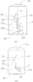
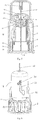
- Drawing marks are illustrated as follows: 1-needle hub, 11-needle tube assembly base, 12-needle tube, 13-clamping column, 14- insulin pen assembly part, 15-annular cavity, and 16-annular protrusion; 2-trigger protector, 21-guide groove, 22-lug boss, and 23-through hole; 201-trigger protector patient end, 202-trigger protector machine end, 211-first guide section, 212-initial fixing portion, 213-transition section, 214-second guide section, 215-tail end fixing portion, and 216-tongue piece; 3-clamping-fixing piece, 31-mounting base, 32-clamping jaw, and 33-groove; 4- spring; 5-shell, and 51-sleeve; 6-opening sealing paper.
- a safety insulin pen needle comprises a needle hub 1.
- an insulin pen assembly part 14 is arranged at one end of the needle hub 1, the diameter of the assembly part is greater than the rest part of the needle hub, the inner side surface of the assembly part is provided with a thread or an embedding opening configured to match with an insulin injection device (such as an insulin pen), and the outer side surface of the assembly part is provided with an annular protrusion 16 in a circle.
- a needle tube assembly base 11 is arranged at the centre of the other end of the needle hub 1, a needle tube 12 is arranged on the needle tube assembly base 11, and the needle tube 12 is positioned on the axial line of the needle hub 1.
- An annular cavity 15 is arranged between the needle tube assembly base 11 on the needle hub 1 and the side wall of the needle hub; meanwhile, at least one protruded clamping column 13 is arranged at the upper part of the outer side wall of the needle hub 1; especially, in the present embodiment, the number of the clamping columns 13 is three, and the three clamping columns are uniformly distributed on the outer side wall of the needle hub at the same height.
- the needle hub 1 is externally sleeved with a trigger protector 2 matched with the needle hub 1 in size.
- the trigger protector 2 is in a sleeve shape, and two ends of the trigger protector 2 are respectively an opening machine end 202 and a patient end 201 away from the machine end, a lug boss 22 extending to the machine end is arranged at the centre of the inside of the patient end 201, and an opening 23 is formed in the centre of the lug boss for the needle tube 12 to pass through.
- Each guide groove 21 comprises a first guide section 211, a second guide section 214 and a transition section 213 connected between the first guide section and the second guide section, wherein the starting end of the first guide section is an initial fixing portion 212, the tail end of the first guide section 211 is connected with the starting end of the transition section 213, and the starting end of the first guide section is farther away from the patient end 201 than the tail end of the first guide section; the tail end of the transition section 213 is connected with the starting end of the second guide section 214, the tail end of the second guide section is a tail end fixing portion 215, and the tail end of the second guide section is closer to the machine end 202 than the starting end of the second guide section.
- an included angle a between the central axis n of the transition section 213 and the axis m of the trigger protector is preferably not more than 45 degrees, and a can be 0 degree.
- the guide groove 21 in the trigger protector 2 is provided with an elastic tongue piece 216 in the second guide section 214.
- the minimum distance between the tongue piece and the upper edge of the second guide section 214 is slightly smaller than the diameter of the clamping column 13 on the needle hub 1, so that the clamping column 13 can pass through the clearance, enter the second guide section 214 from the transition section 213 and reach the tail end fixing portion 215.
- the clamping column 13 is positioned at the tail end fixing portion 215, the clamping column 13 can not be easily separated from the tail end fixing portion 215 due to the blocking of the tongue piece 216, and thus the trigger protector 2 cannot return to the initial position again.
- the safety insulin pen needle in the present embodiment also comprises a spring 3, and the spring 3 is arranged between the needle hub 1 and the trigger protector 2; especially, the spring 3 is stably arranged between the annular cavity 15 in the needle hub 1 and the lug boss 22 in the trigger protector 2.
- the safety insulin pen needle provided by the invention is further provided with a shell 4 outside the needle hub 1 and the trigger protector 2.
- the insulin injection needle is protected by the shell 4 before use, so that the insulin injection needle is prevented from being contaminated or being accidentally and mistakenly touched.
- Opening sealing paper/film 6 is further arranged at the opening end of the shell 5 to adhere to or seal the opening end, so that the needle hub 1 and the needle tube 12 inside the shell 4 are in a closed environment before use so as to avoid being contaminated by the outside.
- the opening sealing paper/film 6 at the opening part of the shell 5 is firstly torn off, and the insulin pen assembly part 14 on the needle hub 1 is mounted on the insulin pen; then the shell 4 is removed, so that the needle tube 12 is exposed, and thus the injection is performed.
- the safety insulin pen needle provided by the present invention Before the injection, the safety insulin pen needle provided by the present invention is in a non-triggered state, the clamping column 13 on the outer edge of the side wall of the needle hub 1 is positioned in the initial fixing portion 212 of the guide groove 21 on the side wall of the trigger protector 2, the spring 3 is compressed at the moment, and the trigger protector 2 bears an upward elastic force of the spring; meanwhile, the starting end of the first guide section is farther away from the patient end than the tail end of the first guide section, so that the clamping column 13 cannot slide out of the initial fixing portion 212, thus effectively preventing the trigger protector from being falsely triggered; the needle tube 12 extends out of the trigger protector through the through hole 23 in the patient end of the trigger protector.
- the safety insulin pen needle in the embodiment can be automatically triggered only in the use process, and has no additional needle sheath and other structures before use like the traditional insulin pen needle, therefore, medical staff or the patient can freely select the needle insertion angle, and the safety insulin pen needle provided by the invention is more convenient to use than the existing safety needle for that only the 90-degree needle insertion angle can be selected. Meanwhile, the better patient experience can be achieved in the injection process.
- the section, exposed out of the trigger protector 2, of the needle tube 12 is inserted into the human body, the top end of the trigger protector 2 is in contact with the human body at the moment, and the spring 3 is compressed to retract due to the acting force of the human body; meanwhile, the clamping column 13 enters the first guide section 211 from the initial fixing portion 212 of the guide groove of the trigger protector 2, and interacts with the upper edge of the first guide section 211, so that the trigger protector 2 rotates at a certain angle.
- the clamping column 13 is separated from the first guide section 211 and enters the starting end of the transition section 213, and then slides into the starting end of the transition section 213.
- the trigger protector 2 bounces to the direction of the needle tube 12 under the action of the elastic force of the spring 3, and the clamping column 13 slides down along the transition section 213 and further enters the tail end fixing portion 215 through the second guide section 214.
- the needle tube 12 is positioned in the trigger protector 2, so that the needle tube 12 is immediately protected, and the cross-infection caused by accidentally and mistakenly touching the used insulin injection needle exposed to the outside is avoided.
- the tail end of the second guide section is closer to the machine end than the starting end of the second guide section, and at this moment the trigger protector still bears the elastic force of the spring towards the patient end, so that the clamping column cannot slide out of the tail end fixing portion.
- the guide groove in the trigger protector is provided with an elastic tongue piece in the second guide section, so that the clamping column can be more effectively prevented from sliding out of the tail end fixing portion, and thus a needle head is prevented from being exposed out of the trigger protector.
- the technical purpose and beneficial effects of the present invention can be achieved by the embodiments of the present invention adopting the above-mentioned technical solutions.
- the clamping columns are possibly separated from the tail end fixing portion, and even return to the initial fixing portion to be repeatedly used, a further improvement on the present invention is made by inventors.
- the safety insulin pen needle provided by the present invention also comprises a clamping-fixing piece 3.
- Fig. 5 and Fig. 6 the safety insulin pen needle provided by the present invention also comprises a clamping-fixing piece 3.
- the clamping-fixing piece 3 comprises a mounting base 31 matched with the insulin pen assembly part 14 on the needle hub 1 and two elastic clamping jaws 32 extending from the mounting base 31 to the patient end 201 of the trigger protector 2, and the elastic clamping jaws 32 are in clamping fit with the outer wall of the upper part of the machine end of the trigger protector before the clamping columns fall into the tail end fixing portion.
- a groove 33 in a circle is formed inside the mounting base 31 of the clamping-fixing piece 3, and is configured to be matched with an annular protrusion 16 on the outer side surface of the insulin pen assembly part 14 on the needle hub 1, and the clamping-fixing piece 3 is arranged on the insulin pen assembly part 14.
- a plurality of uniformly distributed protruded strips or embedding grooves are arranged on the outer side surface of the mounting base 31, and embedding openings or protruded strips matched with the above-mentioned protruded strips or embedding grooves are arranged at the opening end of the shell 4, and are configured to mount the shell 4 on the clamping-fixing piece 3.
- the end parts of the two clamping jaws 32 of the clamping-fixing piece 3 are positioned at the upper part of the machine end 202 of the trigger protector 2, and cling to the outer wall of the trigger protector under the action of elastic force.
- the lower edge of the machine end moves up, so that the end parts of the two clamping jaws 32 of the clamping-fixing piece 3 are positioned below the bottom of the machine end of the trigger protector, and retract towards each other, and the distance between the end parts of the two clamping jaws is smaller than the outer diameter of the trigger protector; at this moment, the end parts of the clamping jaws are propped against the bottom of the machine end of the trigger protector, or a small section of clearance exists between the end part of each of the clamping jaws and the bottom of the machine end, but the width of each section of clearance is smaller than the distance between the needle head of the needle tube and the end part of the patient end of the trigger protector.
- the two clamping jaws 32 of the clamping-fixing piece 3 can be in clamping fit with the edge of the bottom of the machine end of the trigger protector.
- the above-mentioned clamping-fixing piece is arranged, so that the trigger protector difficultly returns to the initial position again even under the action of external force, and thus the needle head cannot be exposed to the outside of the trigger protector after completing the injection, and the repeated use of the safety insulin pen needle provided by the present invention is effectively avoided.
Landscapes
- Health & Medical Sciences (AREA)
- Engineering & Computer Science (AREA)
- Heart & Thoracic Surgery (AREA)
- Vascular Medicine (AREA)
- Anesthesiology (AREA)
- Biomedical Technology (AREA)
- Hematology (AREA)
- Life Sciences & Earth Sciences (AREA)
- Animal Behavior & Ethology (AREA)
- General Health & Medical Sciences (AREA)
- Public Health (AREA)
- Veterinary Medicine (AREA)
- Environmental & Geological Engineering (AREA)
- Infusion, Injection, And Reservoir Apparatuses (AREA)
Claims (10)
- Sicherheits-Insulin-Pen-Nadel für einen Insulin-Pen, einen Nadelansatz (1) und eine Nadelrohranordnungsbasis (11) umfassend, die an dem Nadelansatz (1) angeordnet ist, wobei an der Nadelrohranordnungsbasis (11) ein Nadelrohr (12) angeordnet ist,
wobei die Nadelrohranordnungsbasis (11) an der Mitte eines Endes des Nadelansatzes (1) angeordnet ist und ein Insulin-Pen-Anordnungsteil (14), das mit der Insulininjektionsvorrichtung übereinstimmt, am anderen Ende des Nadelansatzes (1) angeordnet ist, wobei an der äußeren Seitenwand des Nadelansatzes (1) an einem Ende nahe der Nadelrohranordnungsbasis (11) außerdem mindestens eine hervorstehende Klemmnase (13) angeordnet ist,
wobei die Sicherheits-Insulin-Pen-Nadel außerdem einen Auslöseschutz (2) umfasst, der außen auf den Nadelansatz (1) aufgeschoben ist, wobei der Auslöseschutz (2) in Form einer Hülse vorliegt, wobei zwei Enden des Auslöseschutzes (2) ein offenes Maschinenende (202) beziehungsweise ein vom Maschinenende (202) entferntes Patientenende (201) sind, wobei in dem Patientenende (201) eine Durchgangsöffnung (23) für das Nadelrohr (12) zum Hindurchführen gebildet ist, wobei in der Seitenwand des Auslöseschutzes (2) mindestens eine Führungsrille (21) gebildet ist, die mit der Klemmnase (13) am Nadelansatz (1) übereinstimmt, wobei die Führungsrille (21) zumindest mit einem Anfangsbefestigungsabschnitt (212) und einem Endstückbefestigungsabschnitt (215) versehen ist, wobei der Anfangsbefestigungsabschnitt (212) nahe dem Patientenende (201) liegt und der Endstückbefestigungsabschnitt (215) entfernt vom Patientenende (201) liegt, wobei die Klemmnase (13) an dem Nadelansatz (1) in die Führungsrille (21) im Auslöseschutz (2) eingebettet ist, um den Nadelansatz (1) und den Auslöseschutz (2) beweglich zu verbinden, wobei sich das Nadelrohr (12) durch die Durchgangsöffnung (23) aus dem Auslöseschutz (2) heraus erstreckt, wenn die Klemmnase (13) an dem Anfangsbefestigungsabschnitt (212) positioniert ist, und das Nadelrohr (12) an dem Auslöseschutz (2) positioniert ist, wenn die Klemmnase (13) am Endstückbefestigungsabschnitt (215) positioniert ist,
wobei die Sicherheits-Insulin-Pen-Nadel außerdem eine Feder (4) umfasst, wobei die Feder (4) zwischen dem Nadelansatz (1) und dem Auslöseschutz (2) angeordnet ist und die Richtung der elastischen Kraft der Feder (4) gleich der Achsrichtung des Auslöseschutzes (2) ist, und wobei in dem Patientenende (201) des Auslöseschutzes (2) eine sich nach unten erstreckende Lagernabe (22) angeordnet ist,
wobei die Sicherheits-Insulin-Pen-Nadel dadurch gekennzeichnet ist, dass sie ferner einen ringförmigen Hohlraum (15) umfasst, der zwischen der Nadelrohranordnungsbasis (11) und der äußeren Seitenwand des Nadelansatzes (1) angeordnet ist, dass ein Ende der Feder (4) in dem ringförmigen Hohlraum (15) in dem Nadelansatz (1) angeordnet ist und das andere Ende der Feder (4) auf der Lagernabe (22) in dem Patientenende (201) des Auslöseschutzes (2) angeordnet ist,
wobei die Sicherheits-Insulin-Pen-Nadel ferner dadurch gekennzeichnet ist, dass während der Injektion, wenn das Nadelrohr (12) in den menschlichen Körper eingeführt ist, das obere Ende des Auslöseschutzes (2) in Kontakt mit dem menschlichen Körper steht und die Feder (4) komprimiert wird, um infolge der Kraft, die durch den menschlichen Körper wirkt, zurückgezogen zu werden, wobei die Klemmnase (13) unterdessen in einen ersten Führungsteilabschnitt (211) des Anfangsbefestigungsabschnitts (212) der Führungsrille (21) des Auslöseschutzes (2) eintritt und mit dem oberen Rand des ersten Führungsteilabschnitts (211) interagiert, so dass sich der Auslöseschutz (2) um einen bestimmten Winkel dreht, bis die Klemmnase (13) von dem ersten Führungsteilabschnitt (211) getrennt wird und in das Vorderstück eines Übergangsteilabschnitts (213) eintritt, wobei die Feder (4) den Auslöseschutz (2) zwingt, sich zum Patientenende (201) zu bewegen und die Klemmnase (13) durch einen Übergangsteilabschnitt (213), sich zum Endstückbefestigungsabschnitt (215) zu bewegen, wenn das Nadelrohr (12) aus dem menschlichen Körper gezogen wird. - Sicherheits-Insulin-Pen-Nadel nach Anspruch 1, dadurch gekennzeichnet, dass außerhalb des Nadelansatzes (1) ein Klemmbefestigungsstück (3) angeordnet ist und das Klemmbefestigungsstück (3) mit elastischen Klemmbacken (32) versehen ist, die geeignet sind, mit dem Auslöseschutz (2) in Übereinstimmung gebracht zu werden, wobei die Klemmbacken (32) im Klemmsitz mit der Außenwand des oberen Teils des Maschinenendes (202) des Auslöseschutzes (2) stehen, wenn die Klemmnase (13) an dem Anfangsbefestigungsabschnitt (212) positioniert ist, wobei die Klemmbacken (32) unter dem Boden des Maschinenendes (202) des Auslöseschutzes (2) oder in einem Klemmsitz mit dem Rand des Bodens des Maschinenendes (202) des Auslöseschutzes (2) positioniert sind, wenn die Klemmnase (13) am Endstückbefestigungsabschnitt (215) positioniert ist.
- Sicherheits-Insulin-Pen-Nadel nach Anspruch 1 oder 2, dadurch gekennzeichnet, dass die Führungsrille (21) den ersten Führungsteilabschnitt (211), einen zweiten Führungsteilabschnitt (214) und den Übergangsteilabschnitt (213), der zwischen dem ersten Führungsteilabschnitt (211) und dem zweiten Führungsteilabschnitt (214) eingebunden ist, umfasst, dass das Vorderstück des ersten Führungsteilabschnitts (211) der Anfangsbefestigungsabschnitt (212) ist, das Endstück des ersten Führungsteilabschnitts (211) mit dem Vorderstück des Übergangsteilabschnitts (213) verbunden ist, das Endstück des Übergangsteilabschnitts (213) mit dem Vorderstück des zweiten Führungsteilabschnitts (214) verbunden ist und das Endstück des zweiten Führungsteilabschnitts (214) der Endstückbefestigungsabschnitt (215) ist, dass das Vorderstück des ersten Führungsteilabschnitts (211) weiter weg von dem Patientenende (201) als das Endstück des ersten Führungsteilabschnitts (211) liegt und das Endstück des zweiten Führungsteilabschnitts (214) näher am Maschinenende (202) als das Vorderstück des zweiten Führungsteilabschnitts (214) liegt.
- Sicherheits-Insulin-Pen-Nadel nach einem der Ansprüche 1 bis 3, dadurch gekennzeichnet, dass zumindest einer des Anfangsbefestigungsabschnitts (212) und des Endstückbefestigungsabschnitts (215) mit einer unidirektionalen Eintritts-Austritts-Struktur versehen sind.
- Sicherheits-Insulin-Pen-Nadel nach Anspruch 4, dadurch gekennzeichnet, dass die unidirektionale Eintritts-Austritts-Struktur ein Verriegelungsmechanismus oder ein elastisches Zungenstück (216) ist.
- Sicherheits-Insulin-Pen-Nadel nach Anspruch 3, dadurch gekennzeichnet, dass ein eingeschlossener Winkel zwischen der Mittelachsenrichtung des Übergangsteilabschnitts (213) der Führungsrille (21) und der Achsrichtung des Auslöseschutzes (2) nicht mehr als 45 Grad beträgt.
- Sicherheits-Insulin-Pen-Nadel nach einem der Ansprüche 1 bis 6, dadurch gekennzeichnet, dass sie außerdem eine Ummantelung (5) umfasst, wobei die Ummantelung (5) in Form einer Hülse vorliegt und außerhalb des Nadelansatzes (1) und des Auslöseschutzes (2) angeordnet ist, wobei ein Ende der Ummantelung (5) geschlossen ist und die Ummantelung (5) im Inneren mit einer sich einwärts erstreckenden Hülse (51) versehen ist, um das Nadelrohr (12) zu schützen.
- Sicherheits-Insulin-Pen-Nadel nach Anspruch 7, dadurch gekennzeichnet, dass das Klemmbefestigungsstück (3) mit einer Montagebasis (31) versehen ist, die mit dem Insulin-Pen-Anordnungsteil (14) des Nadelansatzes (1) übereinstimmt, und die elastischen Klemmbacken (32) an der Montagebasis (31) angeordnet sind, dass an der äußeren Seitenfläche der Montagebasis (31) gleichmäßig verteilte hervorstehende Streifen oder eingebettete Rillen (33) angeordnet sind und an der inneren Seitenfläche des offenen Endes der Ummantelung (5) eingebettete Öffnungen oder hervorstehende Streifen angeordnet sind, die mit den hervorstehenden Streifen oder den eingebetteten Rillen (33) übereinstimmen.
- Sicherheits-Insulin-Pen-Nadel nach Anspruch 8, dadurch gekennzeichnet, dass die Montagebasis (31) des Klemmbefestigungsstücks (3) mit einer Führungshülse versehen ist, welche den Auslöseschutz (2) in einer Gleitpassung umhüllt, wobei die Führungshülse mit einer Umgehungsöffnung versehen ist und die elastische Klemmbacke (32) in der Umgehungsöffnung angeordnet ist.
- Sicherheits-Insulin-Pen-Nadel nach Anspruch 9, dadurch gekennzeichnet, dass die Ummantelung (5) an der Montagebasis (31) des Klemmbefestigungsstücks (3) angeordnet und mit einem Öffnungs-Abdichtpapier / einer Öffnungsabdichtfolie (6) versehen ist, um am Öffnungsende an der Montagebasis (31) zu haften oder dieses abzudichten.
Applications Claiming Priority (3)
| Application Number | Priority Date | Filing Date | Title |
|---|---|---|---|
| CN201410590229.5A CN104307072A (zh) | 2014-10-29 | 2014-10-29 | 安全式胰岛素笔针 |
| CN201410779947.7A CN104491955B (zh) | 2014-10-29 | 2014-12-17 | 安全式胰岛素笔针 |
| PCT/CN2015/091924 WO2016066014A1 (zh) | 2014-10-29 | 2015-10-14 | 安全式胰岛素笔针 |
Publications (3)
| Publication Number | Publication Date |
|---|---|
| EP3141276A1 EP3141276A1 (de) | 2017-03-15 |
| EP3141276A4 EP3141276A4 (de) | 2017-08-23 |
| EP3141276B1 true EP3141276B1 (de) | 2020-03-18 |
Family
ID=52362470
Family Applications (1)
| Application Number | Title | Priority Date | Filing Date |
|---|---|---|---|
| EP15855618.3A Active EP3141276B1 (de) | 2014-10-29 | 2015-10-14 | Insulinstift mit sicherheitsnadel |
Country Status (4)
| Country | Link |
|---|---|
| US (1) | US10022505B2 (de) |
| EP (1) | EP3141276B1 (de) |
| CN (3) | CN104307072A (de) |
| WO (1) | WO2016066014A1 (de) |
Families Citing this family (57)
| Publication number | Priority date | Publication date | Assignee | Title |
|---|---|---|---|---|
| CN104307072A (zh) * | 2014-10-29 | 2015-01-28 | 杭州普昂医疗科技有限公司 | 安全式胰岛素笔针 |
| CN104771813B (zh) * | 2015-04-28 | 2017-08-22 | 苏州施莱医疗器械有限公司 | 一次性安全胰岛素注射针头 |
| CN104771815B (zh) * | 2015-04-28 | 2017-05-03 | 苏州施莱医疗器械有限公司 | 带针尖保护的胰岛素注射针头 |
| CN104771814B (zh) * | 2015-04-28 | 2017-11-21 | 苏州施莱医疗器械有限公司 | 一次性安全型胰岛素注射针头 |
| CN107735127A (zh) * | 2015-07-01 | 2018-02-23 | 益普生制药公司 | 注射器组件 |
| JP6336008B2 (ja) | 2015-11-23 | 2018-06-06 | ジェムティア メディカル (シャンハイ) インコーポレイテッド | 針刺し装置 |
| EP3269411B1 (de) | 2015-11-23 | 2024-03-06 | Gemtier Medical (Shanghai) Inc. | Nadelpunktionsvorrichtung |
| CN106730139B (zh) * | 2015-11-23 | 2019-06-25 | 上海金塔医用器材有限公司 | 针刺装置 |
| CN108367126B (zh) | 2016-03-02 | 2020-12-25 | 群康生技股份有限公司 | 安全针头 |
| CA3014777C (en) * | 2016-03-16 | 2021-04-20 | Eli Lilly And Company | Medication injection device with automatic needle retraction following injection |
| JP1565215S (de) * | 2016-05-16 | 2016-12-12 | ||
| CN105944190B (zh) * | 2016-05-30 | 2022-05-27 | 浙江康德莱医疗器械股份有限公司 | 安全胰岛素笔配套用针 |
| USD938022S1 (en) * | 2016-08-10 | 2021-12-07 | Owen Mumford Limited | Safety pen needle |
| USD847981S1 (en) * | 2016-08-10 | 2019-05-07 | Owen Mumford Limited | Safety pen needle |
| KR101928297B1 (ko) * | 2016-09-08 | 2018-12-12 | 이오플로우(주) | 약액 주입장치 |
| CN108113883A (zh) * | 2016-11-29 | 2018-06-05 | 南方医科大学珠江医院 | 抽液容器及抽液方法 |
| US10814073B2 (en) | 2016-12-13 | 2020-10-27 | Becton, Dickinson And Company | Safety device with collapsible housing and trigger activation |
| US10661026B2 (en) * | 2016-12-13 | 2020-05-26 | Becton, Dickinson And Company | Safety needle device |
| CN107050573A (zh) * | 2017-05-03 | 2017-08-18 | 贝普医疗科技有限公司 | 一种医用注射器 |
| CN107050572B (zh) * | 2017-05-03 | 2024-03-01 | 贝普医疗科技股份有限公司 | 一种医用注射器 |
| EP3406283B1 (de) * | 2017-05-26 | 2024-11-20 | Embecta Corp. | Stiftnadel |
| CN107243100A (zh) * | 2017-07-17 | 2017-10-13 | 安徽宏宇五洲医疗器械股份有限公司 | 一种胰岛素注射针 |
| TWI641401B (zh) * | 2017-09-30 | 2018-11-21 | 群康生技股份有限公司 | Safety needle and safety needle device |
| CN111132714A (zh) | 2017-09-30 | 2020-05-08 | 群康生技股份有限公司 | 安全针头及安全针头装置 |
| CN107823761B (zh) * | 2017-12-08 | 2023-08-18 | 宁波美生医疗器材有限公司 | 一种安全胰岛素笔配套用针 |
| CN107928752B (zh) * | 2017-12-23 | 2024-02-27 | 博思研生物技术(苏州)有限公司 | 带一次性使用刀头的外科手术超声刀 |
| US12569620B2 (en) | 2018-01-19 | 2026-03-10 | Birya Biotech, Inc. | Tool for servicing an auto-injector |
| CN110064102A (zh) * | 2018-01-23 | 2019-07-30 | 袁丽 | 一种注射器针头及注射器 |
| CN108404257B (zh) * | 2018-02-06 | 2023-06-30 | 贝普医疗科技股份有限公司 | 安全胰岛素针 |
| CN111712287B (zh) * | 2018-02-16 | 2022-09-09 | 贝克顿迪金森法国公司 | 用于注射组合物的设置有安全针盖的医疗装置 |
| CN108543169B (zh) * | 2018-05-16 | 2023-12-01 | 普昂(杭州)医疗科技股份有限公司 | 一种安全式胰岛素笔针 |
| CN108992745B (zh) | 2018-06-29 | 2020-11-03 | 苏州沙力医疗器械有限公司 | 转动锁定式安全胰岛素注射针头 |
| CN108992744B (zh) | 2018-06-29 | 2020-11-03 | 苏州沙力医疗器械有限公司 | 一种转动锁定式安全胰岛素注射针头 |
| CN108939215A (zh) * | 2018-08-31 | 2018-12-07 | 浙江康德莱医疗器械股份有限公司 | 一种安全注射器 |
| CN110893252B (zh) * | 2018-09-12 | 2025-03-14 | 普昂(杭州)医疗科技股份有限公司 | 一种主动自锁式注射器 |
| CN209500449U (zh) * | 2018-09-29 | 2019-10-18 | 苏州施莱医疗器械有限公司 | 改进型转动式安全胰岛素注射针头 |
| CN109701121B (zh) * | 2018-12-12 | 2024-06-14 | 苏州施莱医疗器械有限公司 | 安全注射针和安全注射组件 |
| US11052201B2 (en) * | 2018-12-17 | 2021-07-06 | Verena Solutions LLC | Protective cover for a dental syringe needle |
| CN109718429B (zh) * | 2019-02-15 | 2024-01-16 | 贝普医疗科技股份有限公司 | 一种安全胰岛素针 |
| USD914208S1 (en) | 2019-06-14 | 2021-03-23 | Owen Mumford Limited | Syringe component |
| USD952136S1 (en) | 2019-06-14 | 2022-05-17 | Owen Mumford Limited | Syringe |
| MY204730A (en) * | 2019-09-26 | 2024-09-11 | Keng Kiong Tay | A safety injection needle assembly |
| WO2021168781A1 (zh) * | 2020-02-28 | 2021-09-02 | 江苏采纳医疗科技有限公司 | 一种安全胰岛素笔针 |
| CN111330117B (zh) * | 2020-03-12 | 2022-01-18 | 江苏谦元医疗科技有限公司 | 安全型胰岛素针头 |
| GB2593466A (en) | 2020-03-23 | 2021-09-29 | Ndm Technologies Ltd | Sterile needle hubs |
| USD959651S1 (en) | 2020-04-08 | 2022-08-02 | Owen Mumford Limited | Medical instrument |
| USD972745S1 (en) | 2020-05-07 | 2022-12-13 | Owen Mumford Limited | Testing device |
| EP4188482A4 (de) * | 2020-07-30 | 2024-08-28 | Koska Family Limited | Systeme und verfahren für vorgefüllte medizinische abgabeanordnungen |
| USD1069617S1 (en) | 2021-03-29 | 2025-04-08 | Owen Mumford Limited | Testing device |
| USD1078052S1 (en) | 2021-11-03 | 2025-06-03 | Owen Mumford Limited | Medical device |
| CN115192828A (zh) * | 2022-06-23 | 2022-10-18 | 安徽宏宇五洲医疗器械股份有限公司 | 一种安全胰岛素笔针 |
| USD1071168S1 (en) | 2022-10-17 | 2025-04-15 | Owen Mumford Limited | Medical injector |
| USD1071161S1 (en) | 2022-10-17 | 2025-04-15 | Owen Mumford Limited | Medical injector |
| USD1077210S1 (en) | 2022-11-18 | 2025-05-27 | Owen Mumford Limited | Medical injector |
| CN116328097A (zh) * | 2023-02-14 | 2023-06-27 | 苏州嘉树医疗科技有限公司 | 一种自动式防针刺注射器 |
| CN117414503A (zh) * | 2023-08-28 | 2024-01-19 | 梵颖(上海)生物科技有限公司 | 一种注射器保护装置及安全注射器 |
| CN117100949B (zh) * | 2023-09-26 | 2024-02-23 | 安徽宏宇五洲医疗器械股份有限公司 | 一种带安全防护式自主注射通用注射针头 |
Family Cites Families (48)
| Publication number | Priority date | Publication date | Assignee | Title |
|---|---|---|---|---|
| GB9200219D0 (en) * | 1992-01-07 | 1992-02-26 | Medimech Int Ltd | Automatic injectors |
| US5514097A (en) * | 1994-02-14 | 1996-05-07 | Genentech, Inc. | Self administered injection pen apparatus and method |
| SE9502285D0 (sv) * | 1995-06-22 | 1995-06-22 | Pharmacia Ab | Improvements related to injections |
| US5634910A (en) * | 1995-09-22 | 1997-06-03 | Ryder International Corporation | Syringe instrument |
| US5843036A (en) * | 1996-08-23 | 1998-12-01 | Becton Dickinson And Company | Non-dosing cartridge for an injection device |
| US6348043B1 (en) * | 1998-12-29 | 2002-02-19 | Mckinley Medical, Lllp | Multi-dose infusion pump providing minimal flow between doses |
| SE9901366D0 (sv) * | 1999-04-16 | 1999-04-16 | Pharmacia & Upjohn Ab | Injector device and method for its operation |
| US20020004652A1 (en) * | 1999-06-18 | 2002-01-10 | Asbaghi Hooman A. | Protective device for a fillable injection syringe |
| US6547764B2 (en) | 2000-05-31 | 2003-04-15 | Novo Nordisk A/S | Double pointed injection needle |
| US6984223B2 (en) * | 2001-11-13 | 2006-01-10 | Becton, Dickinson And Company | Needle safety device |
| EP1448256B1 (de) * | 2001-11-30 | 2006-01-25 | Novo Nordisk A/S | Nadelsicherheitsvorrichtung |
| DE10232412A1 (de) * | 2002-07-17 | 2004-02-05 | Disetronic Licensing Ag | Verabreichungsgerät mit Primingfunktion |
| IL157981A (en) * | 2003-09-17 | 2014-01-30 | Elcam Medical Agricultural Cooperative Ass Ltd | Auto injector |
| MXPA06004155A (es) * | 2003-10-16 | 2006-06-28 | Lilly Co Eli | Dispositivo dipensador de medicacion de dosis fija. |
| DE10351598A1 (de) * | 2003-11-05 | 2005-06-16 | Tecpharma Licensing Ag | Autoinjektionsvorrichtung |
| GB0327136D0 (en) * | 2003-11-21 | 2003-12-24 | Nmt Group Plc | Safety needle |
| CN2678665Y (zh) * | 2003-11-26 | 2005-02-16 | 吕海洋 | 自动防护套管式安全注射器 |
| DE202004006611U1 (de) * | 2004-04-23 | 2005-08-25 | Tecpharma Licensing Ag | Injektionsgerät zur Verabreichung eines injizierbaren Produkts mit gesicherter Dosiereinrichtung |
| FR2884723B1 (fr) * | 2005-04-20 | 2008-03-14 | Becton Dickinson France Soc Pa | Dispositif de protection d'un dispositif d'injection |
| GB2438591B (en) * | 2006-06-01 | 2011-07-13 | Cilag Gmbh Int | Injection device |
| ES2360191T3 (es) * | 2006-12-22 | 2011-06-01 | Novo Nordisk A/S | Ensamblaje de aguja protegible con un protector de seguridad pretensado. |
| US8276583B2 (en) * | 2007-01-17 | 2012-10-02 | Shl Group Ab | Device for delivering medicament |
| KR101160735B1 (ko) * | 2007-03-09 | 2012-07-11 | 일라이 릴리 앤드 캄파니 | 자동 주사 장치의 지연 기구 |
| DE102007019124A1 (de) * | 2007-04-23 | 2008-11-06 | Tecpharma Licensing Ag | Rückdrehbare Dosiervorrichtung für eine Injektionsvorrichtung |
| CN101854967B (zh) * | 2007-09-25 | 2013-06-05 | 贝克顿迪金森法国公司 | 具有能由安全护套移动的解除作用装置的自动注射器 |
| WO2009040602A1 (en) * | 2007-09-25 | 2009-04-02 | Becton Dickinson France | Autoinject0r with deactivating means moveable by a safety shield |
| EP2298394A4 (de) * | 2008-06-20 | 2017-11-22 | Nipro Corporation | Nadelanordnung |
| AU2009265915B2 (en) * | 2008-07-04 | 2012-04-19 | Shl Group Ab | Medicament delivery device with mixing mechanism |
| EP3581224A1 (de) * | 2008-08-05 | 2019-12-18 | Antares Pharma, Inc. | Injektor mit mehrfachdosierung |
| US8858510B2 (en) * | 2009-04-27 | 2014-10-14 | Shl Group Ab | Safety pen needle device |
| CN102470219B (zh) * | 2009-08-21 | 2014-06-18 | Shl集团有限责任公司 | 安全笔针装置 |
| JP5886748B2 (ja) * | 2009-09-30 | 2016-03-16 | サノフィ−アベンティス・ドイチュラント・ゲゼルシャフト・ミット・ベシュレンクテル・ハフツング | 薬物送達デバイスのアセンブリ |
| WO2011039211A1 (en) * | 2009-09-30 | 2011-04-07 | Sanofi-Aventis Deutschland Gmbh | Button member for operating a drive assembly |
| WO2011039232A1 (en) * | 2009-09-30 | 2011-04-07 | Sanofi-Aventis Deutschland Gmbh | Drive mechanism for a drug delivery device |
| US8162882B2 (en) * | 2010-06-23 | 2012-04-24 | Sta-Med, Llc | Automatic-locking safety needle covers and methods of use and manufacture |
| EP2438940A1 (de) * | 2010-10-08 | 2012-04-11 | Sanofi-Aventis Deutschland GmbH | Automatischer Injektor mit Torsionsfeder |
| RU2600205C2 (ru) * | 2011-03-25 | 2016-10-20 | Санофи-Авентис Дойчланд Гмбх | Устройство доставки лекарственных средств |
| EP2510964A1 (de) | 2011-04-11 | 2012-10-17 | Becton Dickinson France | Nadelanordnung und Injektionsvorrichtung mit faltbaren Nadelschutzmitteln |
| EP2578259A1 (de) * | 2011-10-06 | 2013-04-10 | Sanofi-Aventis Deutschland GmbH | Nadelsicherheitsvorrichtung |
| WO2013134465A1 (en) * | 2012-03-07 | 2013-09-12 | West Pharmaceutical Services, Inc. | Low radial profile needle safety device |
| GB201206766D0 (en) * | 2012-04-17 | 2012-05-30 | Univ Antwerpen | Prefillable intradermal delivery device |
| CN103405832B (zh) | 2012-10-30 | 2015-03-25 | 温州市贝普科技有限公司 | 一种安全式胰岛素针 |
| CN202982818U (zh) * | 2012-12-13 | 2013-06-12 | 上海康德莱企业发展集团股份有限公司 | 一种用于两件式安全胰岛素注射器的安全保护套 |
| US10004853B2 (en) | 2012-12-20 | 2018-06-26 | Bencha International Group Inc. | Prefillable auto-retractable safety syringe |
| US9272100B2 (en) * | 2013-08-21 | 2016-03-01 | Becton, Dickinson And Company | Extended hub for a safety pen needle |
| US9078977B2 (en) * | 2013-09-30 | 2015-07-14 | Becton, Dickinson And Company | Dual shielded syringe |
| CA2873770A1 (en) * | 2013-12-10 | 2015-06-10 | Becton, Dickinson And Company | Active safety pen needle assembly |
| CN104307072A (zh) * | 2014-10-29 | 2015-01-28 | 杭州普昂医疗科技有限公司 | 安全式胰岛素笔针 |
-
2014
- 2014-10-29 CN CN201410590229.5A patent/CN104307072A/zh active Pending
- 2014-12-17 CN CN201420798074.XU patent/CN204395141U/zh not_active Expired - Lifetime
- 2014-12-17 CN CN201410779947.7A patent/CN104491955B/zh active Active
-
2015
- 2015-10-14 WO PCT/CN2015/091924 patent/WO2016066014A1/zh not_active Ceased
- 2015-10-14 EP EP15855618.3A patent/EP3141276B1/de active Active
- 2015-10-14 US US15/323,354 patent/US10022505B2/en active Active
Non-Patent Citations (1)
| Title |
|---|
| None * |
Also Published As
| Publication number | Publication date |
|---|---|
| CN104307072A (zh) | 2015-01-28 |
| WO2016066014A1 (zh) | 2016-05-06 |
| CN104491955A (zh) | 2015-04-08 |
| US20170143912A1 (en) | 2017-05-25 |
| CN204395141U (zh) | 2015-06-17 |
| US10022505B2 (en) | 2018-07-17 |
| EP3141276A1 (de) | 2017-03-15 |
| CN104491955B (zh) | 2018-07-13 |
| EP3141276A4 (de) | 2017-08-23 |
Similar Documents
| Publication | Publication Date | Title |
|---|---|---|
| EP3141276B1 (de) | Insulinstift mit sicherheitsnadel | |
| CN104203327B (zh) | 导管设备 | |
| EP3052165B1 (de) | Nadelrückzugsmechanismus für einen autoinjektor | |
| US7678080B2 (en) | Intravenous catheter introducing device | |
| US8382719B2 (en) | Method of delivery with needle shield rotation and alignment | |
| US11058828B2 (en) | Safe pen needle | |
| CN102046229B (zh) | 具有径向可动锁定元件的针保护组件 | |
| EP2442855B1 (de) | Sicherheitsstiftnadelvorrichtung | |
| CN103957971B (zh) | 针安全装置 | |
| CN107810022B (zh) | 包括接合针的注射器 | |
| US20160228652A1 (en) | Needle retraction mechanism for autoinjector | |
| CN102099067A (zh) | 针头尖端弹簧保护器 | |
| EP2985049B1 (de) | Schmetterlingsnadelanordnung und schmetterlingsnadelschutzhülse | |
| CN107921222A (zh) | 注射器结合型安全组装体及包括其的安全注射器 | |
| WO2018111797A3 (en) | SAFETY DEVICE FOR SYRINGE | |
| CN110893252A (zh) | 一种主动自锁式注射器 | |
| AU2018333537B2 (en) | Syringe with locking mechanism | |
| JP6171001B2 (ja) | 安全注射器および針シールド | |
| US12115362B2 (en) | Microcartridge | |
| CN204411424U (zh) | 防针刺注射器 | |
| CN209695207U (zh) | 自动回针的安全采血针 | |
| US20240139428A1 (en) | Safety Device for Mounting Onto a Drug Delivery Device | |
| JP5606119B2 (ja) | 穿刺針組立体 | |
| US11224701B1 (en) | Single dose disposable syringe with needle protector | |
| CN209301904U (zh) | 一种主动自锁式注射器 |
Legal Events
| Date | Code | Title | Description |
|---|---|---|---|
| STAA | Information on the status of an ep patent application or granted ep patent |
Free format text: STATUS: THE INTERNATIONAL PUBLICATION HAS BEEN MADE |
|
| PUAI | Public reference made under article 153(3) epc to a published international application that has entered the european phase |
Free format text: ORIGINAL CODE: 0009012 |
|
| STAA | Information on the status of an ep patent application or granted ep patent |
Free format text: STATUS: REQUEST FOR EXAMINATION WAS MADE |
|
| 17P | Request for examination filed |
Effective date: 20161209 |
|
| AK | Designated contracting states |
Kind code of ref document: A1 Designated state(s): AL AT BE BG CH CY CZ DE DK EE ES FI FR GB GR HR HU IE IS IT LI LT LU LV MC MK MT NL NO PL PT RO RS SE SI SK SM TR |
|
| AX | Request for extension of the european patent |
Extension state: BA ME |
|
| A4 | Supplementary search report drawn up and despatched |
Effective date: 20170725 |
|
| RIC1 | Information provided on ipc code assigned before grant |
Ipc: A61M 5/32 20060101AFI20170719BHEP Ipc: A61M 5/34 20060101ALI20170719BHEP Ipc: A61M 5/20 20060101ALN20170719BHEP |
|
| DAV | Request for validation of the european patent (deleted) | ||
| DAX | Request for extension of the european patent (deleted) | ||
| GRAP | Despatch of communication of intention to grant a patent |
Free format text: ORIGINAL CODE: EPIDOSNIGR1 |
|
| STAA | Information on the status of an ep patent application or granted ep patent |
Free format text: STATUS: GRANT OF PATENT IS INTENDED |
|
| RIC1 | Information provided on ipc code assigned before grant |
Ipc: A61M 5/20 20060101ALN20190829BHEP Ipc: A61M 5/32 20060101AFI20190829BHEP Ipc: A61M 5/34 20060101ALI20190829BHEP |
|
| RIC1 | Information provided on ipc code assigned before grant |
Ipc: A61M 5/20 20060101ALN20190912BHEP Ipc: A61M 5/32 20060101AFI20190912BHEP Ipc: A61M 5/34 20060101ALI20190912BHEP |
|
| INTG | Intention to grant announced |
Effective date: 20191002 |
|
| GRAS | Grant fee paid |
Free format text: ORIGINAL CODE: EPIDOSNIGR3 |
|
| RIN1 | Information on inventor provided before grant (corrected) |
Inventor name: HU, CHAOYU |
|
| GRAA | (expected) grant |
Free format text: ORIGINAL CODE: 0009210 |
|
| STAA | Information on the status of an ep patent application or granted ep patent |
Free format text: STATUS: THE PATENT HAS BEEN GRANTED |
|
| AK | Designated contracting states |
Kind code of ref document: B1 Designated state(s): AL AT BE BG CH CY CZ DE DK EE ES FI FR GB GR HR HU IE IS IT LI LT LU LV MC MK MT NL NO PL PT RO RS SE SI SK SM TR |
|
| REG | Reference to a national code |
Ref country code: GB Ref legal event code: FG4D |
|
| REG | Reference to a national code |
Ref country code: DE Ref legal event code: R096 Ref document number: 602015049160 Country of ref document: DE |
|
| REG | Reference to a national code |
Ref country code: AT Ref legal event code: REF Ref document number: 1245202 Country of ref document: AT Kind code of ref document: T Effective date: 20200415 Ref country code: IE Ref legal event code: FG4D |
|
| PG25 | Lapsed in a contracting state [announced via postgrant information from national office to epo] |
Ref country code: RS Free format text: LAPSE BECAUSE OF FAILURE TO SUBMIT A TRANSLATION OF THE DESCRIPTION OR TO PAY THE FEE WITHIN THE PRESCRIBED TIME-LIMIT Effective date: 20200318 Ref country code: FI Free format text: LAPSE BECAUSE OF FAILURE TO SUBMIT A TRANSLATION OF THE DESCRIPTION OR TO PAY THE FEE WITHIN THE PRESCRIBED TIME-LIMIT Effective date: 20200318 Ref country code: NO Free format text: LAPSE BECAUSE OF FAILURE TO SUBMIT A TRANSLATION OF THE DESCRIPTION OR TO PAY THE FEE WITHIN THE PRESCRIBED TIME-LIMIT Effective date: 20200618 |
|
| REG | Reference to a national code |
Ref country code: NL Ref legal event code: MP Effective date: 20200318 |
|
| PG25 | Lapsed in a contracting state [announced via postgrant information from national office to epo] |
Ref country code: LV Free format text: LAPSE BECAUSE OF FAILURE TO SUBMIT A TRANSLATION OF THE DESCRIPTION OR TO PAY THE FEE WITHIN THE PRESCRIBED TIME-LIMIT Effective date: 20200318 Ref country code: SE Free format text: LAPSE BECAUSE OF FAILURE TO SUBMIT A TRANSLATION OF THE DESCRIPTION OR TO PAY THE FEE WITHIN THE PRESCRIBED TIME-LIMIT Effective date: 20200318 Ref country code: BG Free format text: LAPSE BECAUSE OF FAILURE TO SUBMIT A TRANSLATION OF THE DESCRIPTION OR TO PAY THE FEE WITHIN THE PRESCRIBED TIME-LIMIT Effective date: 20200618 Ref country code: GR Free format text: LAPSE BECAUSE OF FAILURE TO SUBMIT A TRANSLATION OF THE DESCRIPTION OR TO PAY THE FEE WITHIN THE PRESCRIBED TIME-LIMIT Effective date: 20200619 Ref country code: HR Free format text: LAPSE BECAUSE OF FAILURE TO SUBMIT A TRANSLATION OF THE DESCRIPTION OR TO PAY THE FEE WITHIN THE PRESCRIBED TIME-LIMIT Effective date: 20200318 |
|
| REG | Reference to a national code |
Ref country code: LT Ref legal event code: MG4D |
|
| PG25 | Lapsed in a contracting state [announced via postgrant information from national office to epo] |
Ref country code: NL Free format text: LAPSE BECAUSE OF FAILURE TO SUBMIT A TRANSLATION OF THE DESCRIPTION OR TO PAY THE FEE WITHIN THE PRESCRIBED TIME-LIMIT Effective date: 20200318 |
|
| PG25 | Lapsed in a contracting state [announced via postgrant information from national office to epo] |
Ref country code: SM Free format text: LAPSE BECAUSE OF FAILURE TO SUBMIT A TRANSLATION OF THE DESCRIPTION OR TO PAY THE FEE WITHIN THE PRESCRIBED TIME-LIMIT Effective date: 20200318 Ref country code: EE Free format text: LAPSE BECAUSE OF FAILURE TO SUBMIT A TRANSLATION OF THE DESCRIPTION OR TO PAY THE FEE WITHIN THE PRESCRIBED TIME-LIMIT Effective date: 20200318 Ref country code: LT Free format text: LAPSE BECAUSE OF FAILURE TO SUBMIT A TRANSLATION OF THE DESCRIPTION OR TO PAY THE FEE WITHIN THE PRESCRIBED TIME-LIMIT Effective date: 20200318 Ref country code: SK Free format text: LAPSE BECAUSE OF FAILURE TO SUBMIT A TRANSLATION OF THE DESCRIPTION OR TO PAY THE FEE WITHIN THE PRESCRIBED TIME-LIMIT Effective date: 20200318 Ref country code: IS Free format text: LAPSE BECAUSE OF FAILURE TO SUBMIT A TRANSLATION OF THE DESCRIPTION OR TO PAY THE FEE WITHIN THE PRESCRIBED TIME-LIMIT Effective date: 20200718 Ref country code: RO Free format text: LAPSE BECAUSE OF FAILURE TO SUBMIT A TRANSLATION OF THE DESCRIPTION OR TO PAY THE FEE WITHIN THE PRESCRIBED TIME-LIMIT Effective date: 20200318 Ref country code: CZ Free format text: LAPSE BECAUSE OF FAILURE TO SUBMIT A TRANSLATION OF THE DESCRIPTION OR TO PAY THE FEE WITHIN THE PRESCRIBED TIME-LIMIT Effective date: 20200318 Ref country code: PT Free format text: LAPSE BECAUSE OF FAILURE TO SUBMIT A TRANSLATION OF THE DESCRIPTION OR TO PAY THE FEE WITHIN THE PRESCRIBED TIME-LIMIT Effective date: 20200812 |
|
| REG | Reference to a national code |
Ref country code: AT Ref legal event code: MK05 Ref document number: 1245202 Country of ref document: AT Kind code of ref document: T Effective date: 20200318 |
|
| REG | Reference to a national code |
Ref country code: DE Ref legal event code: R097 Ref document number: 602015049160 Country of ref document: DE |
|
| PLBE | No opposition filed within time limit |
Free format text: ORIGINAL CODE: 0009261 |
|
| STAA | Information on the status of an ep patent application or granted ep patent |
Free format text: STATUS: NO OPPOSITION FILED WITHIN TIME LIMIT |
|
| PG25 | Lapsed in a contracting state [announced via postgrant information from national office to epo] |
Ref country code: ES Free format text: LAPSE BECAUSE OF FAILURE TO SUBMIT A TRANSLATION OF THE DESCRIPTION OR TO PAY THE FEE WITHIN THE PRESCRIBED TIME-LIMIT Effective date: 20200318 Ref country code: DK Free format text: LAPSE BECAUSE OF FAILURE TO SUBMIT A TRANSLATION OF THE DESCRIPTION OR TO PAY THE FEE WITHIN THE PRESCRIBED TIME-LIMIT Effective date: 20200318 Ref country code: AT Free format text: LAPSE BECAUSE OF FAILURE TO SUBMIT A TRANSLATION OF THE DESCRIPTION OR TO PAY THE FEE WITHIN THE PRESCRIBED TIME-LIMIT Effective date: 20200318 |
|
| 26N | No opposition filed |
Effective date: 20201221 |
|
| PG25 | Lapsed in a contracting state [announced via postgrant information from national office to epo] |
Ref country code: PL Free format text: LAPSE BECAUSE OF FAILURE TO SUBMIT A TRANSLATION OF THE DESCRIPTION OR TO PAY THE FEE WITHIN THE PRESCRIBED TIME-LIMIT Effective date: 20200318 |
|
| PG25 | Lapsed in a contracting state [announced via postgrant information from national office to epo] |
Ref country code: SI Free format text: LAPSE BECAUSE OF FAILURE TO SUBMIT A TRANSLATION OF THE DESCRIPTION OR TO PAY THE FEE WITHIN THE PRESCRIBED TIME-LIMIT Effective date: 20200318 |
|
| REG | Reference to a national code |
Ref country code: CH Ref legal event code: PL |
|
| PG25 | Lapsed in a contracting state [announced via postgrant information from national office to epo] |
Ref country code: LU Free format text: LAPSE BECAUSE OF NON-PAYMENT OF DUE FEES Effective date: 20201014 Ref country code: MC Free format text: LAPSE BECAUSE OF FAILURE TO SUBMIT A TRANSLATION OF THE DESCRIPTION OR TO PAY THE FEE WITHIN THE PRESCRIBED TIME-LIMIT Effective date: 20200318 |
|
| REG | Reference to a national code |
Ref country code: BE Ref legal event code: MM Effective date: 20201031 |
|
| PG25 | Lapsed in a contracting state [announced via postgrant information from national office to epo] |
Ref country code: CH Free format text: LAPSE BECAUSE OF NON-PAYMENT OF DUE FEES Effective date: 20201031 Ref country code: BE Free format text: LAPSE BECAUSE OF NON-PAYMENT OF DUE FEES Effective date: 20201031 Ref country code: LI Free format text: LAPSE BECAUSE OF NON-PAYMENT OF DUE FEES Effective date: 20201031 |
|
| PG25 | Lapsed in a contracting state [announced via postgrant information from national office to epo] |
Ref country code: IE Free format text: LAPSE BECAUSE OF NON-PAYMENT OF DUE FEES Effective date: 20201014 |
|
| PG25 | Lapsed in a contracting state [announced via postgrant information from national office to epo] |
Ref country code: TR Free format text: LAPSE BECAUSE OF FAILURE TO SUBMIT A TRANSLATION OF THE DESCRIPTION OR TO PAY THE FEE WITHIN THE PRESCRIBED TIME-LIMIT Effective date: 20200318 Ref country code: MT Free format text: LAPSE BECAUSE OF FAILURE TO SUBMIT A TRANSLATION OF THE DESCRIPTION OR TO PAY THE FEE WITHIN THE PRESCRIBED TIME-LIMIT Effective date: 20200318 Ref country code: CY Free format text: LAPSE BECAUSE OF FAILURE TO SUBMIT A TRANSLATION OF THE DESCRIPTION OR TO PAY THE FEE WITHIN THE PRESCRIBED TIME-LIMIT Effective date: 20200318 |
|
| PG25 | Lapsed in a contracting state [announced via postgrant information from national office to epo] |
Ref country code: MK Free format text: LAPSE BECAUSE OF FAILURE TO SUBMIT A TRANSLATION OF THE DESCRIPTION OR TO PAY THE FEE WITHIN THE PRESCRIBED TIME-LIMIT Effective date: 20200318 Ref country code: AL Free format text: LAPSE BECAUSE OF FAILURE TO SUBMIT A TRANSLATION OF THE DESCRIPTION OR TO PAY THE FEE WITHIN THE PRESCRIBED TIME-LIMIT Effective date: 20200318 |
|
| PGFP | Annual fee paid to national office [announced via postgrant information from national office to epo] |
Ref country code: FR Payment date: 20250929 Year of fee payment: 11 |
|
| PGFP | Annual fee paid to national office [announced via postgrant information from national office to epo] |
Ref country code: DE Payment date: 20251027 Year of fee payment: 11 |
|
| PGFP | Annual fee paid to national office [announced via postgrant information from national office to epo] |
Ref country code: GB Payment date: 20251014 Year of fee payment: 11 |
|
| PGFP | Annual fee paid to national office [announced via postgrant information from national office to epo] |
Ref country code: IT Payment date: 20251008 Year of fee payment: 11 |