EP3141309A1 - Ausklappbarer anschlagstift - Google Patents
Ausklappbarer anschlagstift Download PDFInfo
- Publication number
- EP3141309A1 EP3141309A1 EP16187703.0A EP16187703A EP3141309A1 EP 3141309 A1 EP3141309 A1 EP 3141309A1 EP 16187703 A EP16187703 A EP 16187703A EP 3141309 A1 EP3141309 A1 EP 3141309A1
- Authority
- EP
- European Patent Office
- Prior art keywords
- lever
- reaction
- retaining
- base
- stop
- Prior art date
- Legal status (The legal status is an assumption and is not a legal conclusion. Google has not performed a legal analysis and makes no representation as to the accuracy of the status listed.)
- Granted
Links
Images



Classifications
-
- B—PERFORMING OPERATIONS; TRANSPORTING
- B21—MECHANICAL METAL-WORKING WITHOUT ESSENTIALLY REMOVING MATERIAL; PUNCHING METAL
- B21D—WORKING OR PROCESSING OF SHEET METAL OR METAL TUBES, RODS OR PROFILES WITHOUT ESSENTIALLY REMOVING MATERIAL; PUNCHING METAL
- B21D43/00—Feeding, positioning or storing devices combined with, or arranged in, or specially adapted for use in connection with, apparatus for working or processing sheet metal, metal tubes or metal profiles; Associations therewith of cutting devices
- B21D43/26—Stops
-
- B—PERFORMING OPERATIONS; TRANSPORTING
- B21—MECHANICAL METAL-WORKING WITHOUT ESSENTIALLY REMOVING MATERIAL; PUNCHING METAL
- B21D—WORKING OR PROCESSING OF SHEET METAL OR METAL TUBES, RODS OR PROFILES WITHOUT ESSENTIALLY REMOVING MATERIAL; PUNCHING METAL
- B21D5/00—Bending sheet metal along straight lines, e.g. to form simple curves
- B21D5/002—Positioning devices
-
- B—PERFORMING OPERATIONS; TRANSPORTING
- B21—MECHANICAL METAL-WORKING WITHOUT ESSENTIALLY REMOVING MATERIAL; PUNCHING METAL
- B21D—WORKING OR PROCESSING OF SHEET METAL OR METAL TUBES, RODS OR PROFILES WITHOUT ESSENTIALLY REMOVING MATERIAL; PUNCHING METAL
- B21D5/00—Bending sheet metal along straight lines, e.g. to form simple curves
- B21D5/02—Bending sheet metal along straight lines, e.g. to form simple curves on press brakes without making use of clamping means
- B21D5/0281—Workpiece supporting devices
Definitions
- the present disclosure relates to a mechanical contact device comprising a base, a movable support adapted to move on the base in a direction X and a contact member carried by the support.
- the mechanical contact device can be any device, equipping a machine or an apparatus, and intended to have a working position in which it comes into contact with a workpiece or a tool and to be animated by rapid movements , for example during maintenance or adjustment of the machine or the device.
- the contact member within the meaning of the present disclosure may for example be a tool holder, for example for a drilling or machining tool, equipping a machine or a robot, or even a setting or recovery finger of effort for a workpiece to undergo treatment in a machine.
- the contact member may be a rear stop finger of a press brake.
- the patent application European No 1 264 647 discloses a sheet metal press brake equipped with a mechanical contact device formed by a rear stop device comprising a contact member formed by a stop finger.
- This press brake comprises a frame having on the front side a vertically movable upper apron and a lower plywood deck.
- a sheet to be folded is disposed in the space between the aprons, the rear edge of this sheet abutting against the contact member of the rear stop device to ensure its correct positioning during folding.
- the upper apron is moved down and the tools it carries perform the folding in cooperation with the matrix that carries the lower deck.
- the rates of use of the press brakes are high and the operations of setting up the sheets and adjusting the position of the different components of the press brake must be performed quickly.
- a part of the body of the operator in particular his hands, can be in the space between the upper and lower aprons or in the immediate vicinity of one of these aprons, in particular the apron inferior.
- the entire rear stop device is moved back. At the end of such an operation, this assembly is advanced rapidly forward so that the contact member comes into its working position, in which it performs its function of backstop.
- one or more rear stop devices of the aforementioned type are mounted on a main carriage which, after an adjustment or repositioning operation, quickly advance this device or devices forward.
- the advance movement is effected in two stages, ie a first rapid phase from the extreme backward position to an intermediate position, then a final stage of advancement which, in the zone in which it is likely to strike a part of the body of the operator, operates slowly.
- this hampers the production rates since, overall, the speed of movement of the contact device is affected.
- a mechanical contact device which makes it possible to limit or even avoid the risk of injury to a person or material damage, if a part of a person's body or an object were to be struck by the contact member during an operation or maneuver such as, for example, a adjusting or repositioning a machine or apparatus equipped with the contact device, while substantially overcoming the aforementioned drawbacks.
- the direction X is a horizontal direction of forward-backward motion
- the Y direction is the vertical direction
- the Z direction is a horizontal direction of right-left movement. This is particularly the case when the mechanical contact device is a rear stop device of a press brake.
- the contact member plays its role of mechanical contact, for example a back press brake. Indeed, in this case, the displacement of the mobile support under the effect of a thrust force (towards the rear) exerted in the direction X is restricted, so that the contact member can cooperate by static contact with a piece, for example the rear edge of a sheet to be folded.
- the device defined above does not affect or virtually the normal speed of movement of the contact member and, therefore, does not affect or almost no rate of the machine, for example a press- folder, which is equipped with the mechanical contact device.
- the device comprises two reaction members disposed substantially symmetrically on either side of a plane of symmetry, and the locking arm has two reaction zones which, when the lever is in its rest position, are arranged substantially symmetrically on either side of said plane of symmetry, said plane of symmetry being parallel to the X and Y directions and being defined when the lever is in its rest position.
- this arrangement makes it possible to obtain the same effect during an impact due to a relative displacement between the contact member and an object or the body of a person in the direction Z, in one direction or in the other that is to say, when the Z direction is a right-left horizontal direction, either to the right or to the left.
- the retaining means are able to be controlled between a holding situation in which they are active and oppose the pivoting of the lever, and the release situation in which they are deactivated.
- the retaining means are not permanently effective.
- the retaining means can be controlled in the holding situation when the machine equipped with the mechanical contact device is in operation, for example during folding operations performed in a press brake, and be controlled in the release situation. during machine setting operations prior to or following operation, in particular of the type requiring intervention by an operator.
- the retaining means can be controlled by an electronic control unit.
- reaction surface is at least partly convex.
- the lever axis is carried by the movable support and said at least one reaction member is integral with the base.
- the retaining means comprise a first retaining member integral with the base and a second retaining member carried by the lever.
- one of the first and second retaining members comprises a member selected from a latch, a permanent magnet, an electromagnet and a suction cup, while the other of the first and second retaining members comprises a retaining surface adapted to cooperate with said element.
- the retaining means may also comprise other means, for example a weight carried by the lever or integral with it to naturally recall the lever in its rest position under the effect of gravity.
- This weight can be directly integrated in the lever, for example being formed by a secondary arm, making a angle with the locking arm and having a mass sufficient to return the lever to the rest position. It can also be formed on the locking arm or on another part of the lever, provided that it tends to return it to its rest position.
- Such a weight may form the second retaining member mentioned above.
- the base may have an abutment surface against which a portion of the lever abuts during its return by the weight under the effect of gravity.
- the retaining means may exert permanent retention, for example when one of the first and second retaining members comprises a permanent magnet or a permanent latch that can be unlocked by a force opposing a permanent elastic return in locked situation.
- the retaining means are naturally active and are deactivated during an impact on the contact member, whose intensity exceeds the retaining force exerted by said retaining means.
- the retaining means may be of the controllable type between the restraint situation and the release situation. This is for example the case when one of the first and second retaining members comprises a controlled lock, an electromagnet or a suction cup.
- the retaining means are activated in the retaining situation, for example during folding operations performed in a press brake, and can be deactivated in the release situation, to allow adjustments of the hair press.
- the lever carries a locking stop, permanently recalled in an inactive position and suitable, during a shock on the contact member causing a pivoting of the lever while the retaining means are active, to adopt an active position in which said pivoting of the lever is limited by a contact between said stopper and a fixed abutment of the movable support.
- such a shock may be due to the sudden introduction of a sheet to be folded in the press brake. If the setting up of the sheet caused such a shock on the contact member, then that a bending operation begins, this shock could, if its intensity is very strong, unintentionally release the movement of the lever, exceeding the retaining force exerted by the yet active holding means, thus ensuring that the contact member also moves and so out of its desired working position.
- the aforementioned blocking abutment avoids this since, during such an impact on the contact member, the movable support moves and causes the beginning of pivoting of the lever.
- the blocking stop then in its active position, then prevents the lever from pivoting further through the contact between this blocking stop and the abutment surface integral with the movable support, before the restraint operated by the retaining means ceases to to be effective.
- the lever is thus stopped in a position that is only very slightly rotated, and this restraint, combined with the cooperation between the reaction member secured to the base and the reaction zone of the locking arm, stops the movement of the mobile support relative to the base as long as the retaining means remain active.
- the contact member does not move more than the short stroke that caused the slight pivoting of the lever.
- a shock causes an intense effort that stops immediately.
- the contact between the stopper and the abutment occurs before this effort overcomes the restraining force exerted by the active restraining means. Only if a significant effort is applied sustainably, as in the case where an object is hit by the contact member on the move and would form an obstacle on its course that, depending on its intensity, this effort can overcome the force of restraint exercised by the active restraining means. If this retaining force is exceeded, the retaining means are then deactivated, which allows the locking stop to return to its inactive position, so that the pivoting of the lever is released, which allows the displacement of the organ of contact.
- the blocking stop is useful both when the retaining means are of permanent type (for example with flyweight, latch or permanent magnet) by exerting an exerting retaining force, than when the retaining means are of controllable type. enter here retaining situation and the release situation, and are for example constituted by a controllable lock, an electromagnet or a suction cup.
- the device comprises a stop actuator adapted, during an impact on the contact member, to cooperate with the locking stop to urge the latter in its active position.
- the stop actuator is secured to the second retaining member.
- the stop actuator is adapted to cooperate with the stopper via at least one ramp that has one of the elements comprising the stop actuator and the stopper.
- the displacement of the movable abutment under the effect of the shock is thus facilitated and can operate in a direction different from that of the force exerted on it by the thrust actuator.
- the device comprises means for biasing the lever in the rest position while the locking stop is in contact with the abutment and the retaining means are in the retaining situation.
- a shock may cause a slight pivoting of the lever, but it remains blocked by the contact between the locking stop and the abutment. As soon as this shock produces an instantaneous force, the intensity of which disappears after the impact, the retaining means remain in restraint. In this case, the lever is recalled in a rest situation and the slight displacement of the contact member that occurred during the shock is canceled.
- the second retaining member is able to move relative to a reaction part of the lever which is rigidly connected to the locking arm, the stop actuator is rigidly connected to the second retaining member, and one of the elements comprising the stop actuator and the second retaining member cooperating with said reaction part via an elastic return means.
- said reaction portion is formed on a secondary arm of the lever, the second retaining member and the actuator are disposed on either side of the secondary arm, and a return spring is interposed between the secondary arm and the one of the elements formed by the thrust actuator and the second retaining member.
- the present disclosure also relates to a sheet metal press brake comprising a mechanical contact device of the type described above, forming a backstop device of the press brake, the press brake further comprising a frame having a front side upper apron movable vertically, substantially perpendicular to the X and Z directions, and a lower plywood deck, the base being carried by a main carriage, movable back and forth in the direction X, preferably via a rail system allowing a sliding of the base relative to the main carriage in direction Z.
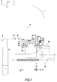
- FIG. 1 On the figure 1 is schematically shown a side cheek of a frame 1 of a press brake, the cheek is shaped like a gooseneck and having on the front side a fixed lower deck 2 whose upper face serves as a support for a folding die 3
- the press brake also comprises an upper apron 4 movable vertically back and forth in the direction Y and carrying at its lower end a folding tool 5 cooperating with the die 3 to, when a sheet 6 is disposed in the press brake, make a folding of this sheet.
- the press brake comprises a rear stop device 10 comprising a base 12, a movable support 14 adapted to move on the base 12 in a front-rear horizontal direction X and a contact member 16, carried by the mobile support 14 and forming in this case a backstop finger of the press brake.
- the contact member is carried by the support via a spacer 18 fixed to the movable support via a pivot axis 19 extending in a horizontal right-left direction Z which, under certain circumstances, allows the spacer and the contact member to rise by pivoting.
- the contact member 16 is therefore disposed at the front of the spacer 18.
- the rear stop device comprises in this case also a rear wedge 17 carried by the support 14 at its rear end.
- the base 12 is carried by a main carriage 20 which is movable back and forth in the direction X, for example via a worm drive system 22.
- the base 12 is carried by the main carriage 20 via a rail system allowing a sliding of the base 12 relative to the main carriage 20 in the left horizontal direction horizontal Z, perpendicular to the plane of the figure.
- the rail system comprises tubes 24 forming rails carried by the main carriage 20 and sliders 26 carrying the base 12.
- the drive system of the slider 26 comprises for example a belt drive device 28 shown in broken line.
- the support 14 rests on the base 12 but can slide relative thereto in the X direction. It can also pivot relative to the base 12 around an axis mobile support 30 oriented in the vertical direction Y.
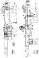
- This axis is embodied by a journal 30 '(see figure 4 ), which is fixed to the base 12 and which passes through an oblong opening 32 of the support 14 so as not to hinder the sliding of the latter in the direction X relative to the base.
- the device comprises a lever 34 which is pivotally mounted about a lever axis 36 which, in the example shown, is carried by the mobile support 14.
- This lever has a locking arm 38 which is pivotally mounted about the lever axis 36.
- figure 4 shows the lever at rest, while the figure 5 shows the lever in a rotated position about the axis 36.
- the device comprises retaining means which, on the figure 4 , are active in a restraint situation and oppose the pivoting of the lever which is thus maintained in its rest position and which, on the figure 5 , are inactivated in a release situation in which the lever can be rotated.
- these retaining means comprise an electromagnet 40 which forms a first retaining member secured to the base 12.
- the lever comprises a second retaining member 42 which, in this case, is carried by a secondary arm 44 of the lever arranged so that, with the locking arm 38, it substantially forms an L, the locking arm forming in this case the small branch of L and being oriented downwards.
- the second retaining element 42 has a surface made of a material sensitive to magnetic attraction, to be held against the electromagnet 40 when the latter is activated.
- the electromagnet could be replaced by a pneumatic sucker, in which case the surface of the second retaining member located opposite the suction cup could be a solid surface (the tapping 46 visible on the Figures 4 and 5 , which will be described later, which may not be traversing).
- the retaining means could for example comprise a latch, comprising for example, as second retaining member carried by the lever 34, a striker formed by a recess or a bore 44 'in an extension 44 "of the arm 44 facing a wall of the base 12 and a bolt, carried by the base and capable of protruding into this striker, and to be retracted into the wall in question of the base.The edge of the hole would then form the retaining surface.
- a latch comprising for example, as second retaining member carried by the lever 34, a striker formed by a recess or a bore 44 'in an extension 44 "of the arm 44 facing a wall of the base 12 and a bolt, carried by the base and capable of protruding into this striker, and to be retracted into the wall in question of the base.The edge of the hole would then form the retaining surface.
- the retaining means may be of the type that can be controlled between the holding situation and the release situation, for example by an ECU electronic control unit controlling one of the retaining members.
- the figure 4 shows such a unit electrically connected to the electromagnet 42. It could be the same for a pneumatic suction pad, or a bolt lockable.
- the retaining means may be of the permanent holding type.
- the retaining means may comprise a flyweight, a permanent magnet, or a permanent latch whose bolt could, however, retract if a large force is exerted on the lever, for example if the lever moves and hits a part or a body part of a person such as an operator.
- the cooperation between the bolt and the strike could be via a ramp tending to recall the bolt in the retracted position during a movement between the striker and the bolt, against a permanent elastic return bolt protruding position , the stiffness of the elastic return being determined to allow the retraction of the bolt only from a given intensity of the efforts between the striker and the bolt.
- the figure 4 shows the retaining means in the retaining situation, and it can be seen in this figure that the lever 34 is in its rest position, in which the locking arm 38 faces reaction members (hereinafter described) provided in a recess 13 of the base in which the locking arm protrudes in this rest position.
- the locking arm 38 of the lever cooperated with the reaction members to allow that the lever is raised, thus escaping the walls of the recess 13, and thus allowing the support 14 and the contact member 16 (and also the spacer 18) to move by pivoting about the axis 30 .
- the lever is returned to a position in which its secondary arm 44 is lowered. This return is made by gravity, under the effect of the weight of the arm 44, the lever being housed in a through window 35 of the support 14.
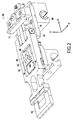
- the spacer 18 has a window 18 'in which, when the spacer and the contact member are in the lowered normal position as in particular on the figures 2 and 6 an extension 14 'of the support projects.
- This as well as various cuts made in particular in the spacer, allow to limit its mass which is useful in the case where one seeks a lightness, for example to limit the inertia during very fast movements.
- the aforesaid extension 14 ' forms a fork and thus has the window 35 between the two arms of this fork, the pivot axis 36 of the lever being embodied by a pin retained in the edges of this window 35.
- the secondary arm 44 of the latter is horizontal and located in the window 35, while the locking arm 38 through this window to be located in the recess 13 of the base 12. Indeed, as one see him on the Figures 4 and 5 , the window 35 is in vertical correspondence with the recess 13 in the working position of the contact member 16.
- the locking arm 38 has two reaction zones 38A and 38B, respectively, which, when the lever is in its rest position and the contact member is in its working position, are arranged substantially symmetrically with respect to each other. on either side of a plane of symmetry P defined by the horizontal direction X and the vertical direction Y.
- the base 12 carries two reaction members, respectively 48A and 48B, to cooperate respectively with each of these two zones. of reaction. These reaction members are arranged substantially symmetrically with respect to the plane P.
- these reaction members are formed on screw heads 50A and 50B, respectively, screwed into branches 12A and 12B, respectively, of the base 12 which delimit between they recess 13 previously defined. These screws, which can be retained by nuts 51A and 51B can thus be adjusted in position so as to be able to precisely adjust the position of the reaction members.
- the distance d can for example be of the order of 5mm to 30mm, in particular of the order of 15mm to 20mm. This distance can be small and it suffices that it allows the desired lever to cause the pivoting of the lever from a given amplitude for the reaction force between the reaction member (s) and the reaction zone (s).
- reaction surfaces formed on the reaction members 48A and 48B are slightly convex which, in the release situation, promotes sliding between the reaction members and the reaction zones of the locking arm, and thus promotes pivoting of the the sink.
- the mechanical contact device comprises means for preventing inadvertent movement of the contact member during an impact occurring while the contact member is in the working position and supposed to be functional to achieve a rear stop for a sheet to be folded by the press brake.
- the lever carries a locking stop which is permanently recalled in an inactive position and which is adapted, during such an impact, to adopt an active position limiting the movement of the lever by a contact between this blocking stop and an abutment surface secured to the movable support 14.
- the lever carries two locking stops, respectively 60A and 60B which are arranged symmetrically on either side of the plane P (considered when the lever is in its position resting and that the contact member is in its working position).
- these locking stops are carried by the secondary arm 44 of the lever.
- this arm 44 has on two opposite edges (in this case respectively its front edge and its rear edge) sliding rails 62 formed recessed in projecting flanges on the upper face of the arm 44.
- the stops 60A and 60B are formed by pieces slidably mounted in these rails and are permanently biased towards each other by return springs 64.
- the arm 44 has a central bore 54 '.
- the second retaining member 42 is not directly formed by the lower face of the arm 44, but it is formed in a plate attached to this arm. In central region, this plate has a tubular extension 66 which passes through the bore 65 of the arm 44.
- a headrest 68 having a substantially U-shaped vertical section whose branches are arranged downwardly is retained relative to the second retaining member 42 at the bottom. using a screw 70 whose rod is screwed into the tapping 46 of the tubular extension 66. In this case, a protective cap 72 is interposed between the screw and the headrest 68.
- a coil spring 74 is disposed around of the tubular extension 66 and is supported, on the one hand, on the upper face of the arm 44 and, on the other hand, on the lower face of the headrest 68.
- This spring therefore tends to permanently remove the headrest of the upper face of the arm 44 and, therefore, to bring the arm 44 of the second retaining member 42.
- the headrest 68 acts as a stop actuator which, during an impact on the contact member, cooperates with the stops 60A and 60B to solicit them in their active stop position.
- the arm 44 acts as a reaction part, which is rigidly connected to the locking arm 38 and with respect to which the second retaining member 42 can move.
- the headrest plays the role of a thrust actuator which is rigidly connected to the second retaining member 42 and which cooperates with the reaction part (arm 44) via the spring 74.
- the figure 9 shows the liberation situation.
- the plate 42 has separated from the electromagnet 40 which has been deactivated, but the springs 64 continue to urge the blocking stops 60A and 60B towards each other.
- the arm 44 can be raised without limiting this pivoting.
- the locking stops escape against abutments 78A and 78B, respectively, located on the sides of the recess 35 of the extension 14 'of the support 14 in which the lever is located.
- the lever can therefore pivot without hindrance, which allows a movement of the contact member avoiding or limiting the damage caused by a contact of this contact member with an obstacle such as a part or a part of the body of a person .
- the arm 44 has driven with it the stops 60A and 60B which then cooperate with the headrest 68 via ramps, respectively 60'A and 60'B located on the inclined upper faces of the stops 60A and 60B.
- the blocking stops then deviate from one another in the Z direction as shown in FIG. figure 10 .
- the stops On their faces opposite the plane P, the stops have shoulders, respectively 60 "A and 60" B, which during movement of the lever upward, come into contact with the abutments 78A and 78B and thus prevent the continuation of the pivoting of the the sink. This one is then blocked in its race.
- the plate 42 (second retaining member) remained retained against the electromagnet 40.
- the retaining force exerted by the electromagnet is of the order of 240 N or more.
- this spring recalls this arm towards the plate 42, which reminds the lever in its rest position and therefore recalls the contact member to its working position.
- the spring 74 works in compression. The effect obtained could be the same with a spring working in extension, which would be interposed between the plate 42 and the arm 44.
- the same elements are visible on the exploded perspective of the figure 12 , on which we better see the conformation of the base 12, with its recess 13 separating two branches within which is held the bowl carrying the electromagnet, on flanges 113 projecting on the inner faces of the recess.
- the passage 50'B serving for the establishment of the screw 50B whose head forms a reaction member is also visible.
- the figure 12 shows the movable support 14, which is seen in particular the oblong window 32, above which there is shown the pin 30 'and the stud 30 "for forming the axis 30 of rotation of the support relative to the base.
- the plate 42 With its tubular extension 68 and the spring 74, is seen to the right of the mobile support 14.
- the remainder of the elements constituting the lever 34 is represented above, the locking arm 38 is recognized, the stops 60A and 60B and their springs 64, as well as the axis 36 of pivoting of the lever.
- the headrest 68 is shown above, but under the cap 72 and the screw 70.
- the base 12, the support 14 and the lever 36 are symmetrical with respect to the plane P (considered when the contact member is in its working position).
- a press brake may comprise, and in general comprises, a plurality of similar rear stop devices, spaced apart from one another along the length of the rails 24.
- the device mechanical contact according to the invention can be any device, equipping a machine or an apparatus, and intended to have a working position in which it comes into contact with a workpiece or a tool and to be driven by rapid movements, for example during maintenance or adjustment of the device or machine.
Landscapes
- Engineering & Computer Science (AREA)
- Mechanical Engineering (AREA)
- Braking Arrangements (AREA)
- Accommodation For Nursing Or Treatment Tables (AREA)
Priority Applications (1)
| Application Number | Priority Date | Filing Date | Title |
|---|---|---|---|
| PL16187703T PL3141309T3 (pl) | 2015-09-08 | 2016-09-07 | Bolec oporowy umożliwiający wysprzęglenie |
Applications Claiming Priority (1)
| Application Number | Priority Date | Filing Date | Title |
|---|---|---|---|
| FR1558325A FR3040643B1 (fr) | 2015-09-08 | 2015-09-08 | Dispositif de contact mecanique, tel qu'une butee arriere pour une presse-plieuse |
Publications (2)
| Publication Number | Publication Date |
|---|---|
| EP3141309A1 true EP3141309A1 (de) | 2017-03-15 |
| EP3141309B1 EP3141309B1 (de) | 2017-11-15 |
Family
ID=54366401
Family Applications (1)
| Application Number | Title | Priority Date | Filing Date |
|---|---|---|---|
| EP16187703.0A Active EP3141309B1 (de) | 2015-09-08 | 2016-09-07 | Ausklappbarer anschlagstift |
Country Status (6)
| Country | Link |
|---|---|
| US (1) | US9682416B2 (de) |
| EP (1) | EP3141309B1 (de) |
| ES (1) | ES2659432T3 (de) |
| FR (1) | FR3040643B1 (de) |
| PL (1) | PL3141309T3 (de) |
| PT (1) | PT3141309T (de) |
Families Citing this family (4)
| Publication number | Priority date | Publication date | Assignee | Title |
|---|---|---|---|---|
| MX2019002783A (es) | 2016-09-09 | 2019-09-04 | Mate Precision Tooling Inc | Sistema de acoplamiento de herramienta plegadora. |
| US10792716B2 (en) * | 2017-06-29 | 2020-10-06 | Mate Precision Tooling, Inc. | Magnetic press brake and machine tooling engagement systems |
| US10953453B2 (en) | 2017-11-06 | 2021-03-23 | Mate Precision Technologies Inc. | Magnetic press brake tooling engagement system |
| CA3014100A1 (en) * | 2018-08-14 | 2020-02-14 | 2446914 Ontario Inc. | Container with an interchangeable liner |
Citations (3)
| Publication number | Priority date | Publication date | Assignee | Title |
|---|---|---|---|---|
| JP2002292430A (ja) * | 2001-04-02 | 2002-10-08 | Amada Co Ltd | ワーク位置決め位置 |
| EP1264647A1 (de) | 2001-05-23 | 2002-12-11 | Amada Europe | Abkantpresse für Bleche mit einer beweglichen Anschlageinrichtung |
| EP2043795B1 (de) * | 2006-07-25 | 2011-03-30 | Trumpf Maschinen Austria GmbH & CO. KG. | Anschlagvorrichtung für eine biegepresse |
Family Cites Families (3)
| Publication number | Priority date | Publication date | Assignee | Title |
|---|---|---|---|---|
| US4055070A (en) * | 1976-08-30 | 1977-10-25 | Dynamics Research Corporation | Gage stop assembly |
| US4411150A (en) * | 1981-10-21 | 1983-10-25 | Houdaille Industries, Inc. | Backgauge structure |
| US5526672A (en) * | 1995-07-20 | 1996-06-18 | Interbold | Press brake backgage |
-
2015
- 2015-09-08 FR FR1558325A patent/FR3040643B1/fr not_active Expired - Fee Related
-
2016
- 2016-09-02 US US15/255,228 patent/US9682416B2/en not_active Expired - Fee Related
- 2016-09-07 EP EP16187703.0A patent/EP3141309B1/de active Active
- 2016-09-07 PT PT161877030T patent/PT3141309T/pt unknown
- 2016-09-07 PL PL16187703T patent/PL3141309T3/pl unknown
- 2016-09-07 ES ES16187703.0T patent/ES2659432T3/es active Active
Patent Citations (3)
| Publication number | Priority date | Publication date | Assignee | Title |
|---|---|---|---|---|
| JP2002292430A (ja) * | 2001-04-02 | 2002-10-08 | Amada Co Ltd | ワーク位置決め位置 |
| EP1264647A1 (de) | 2001-05-23 | 2002-12-11 | Amada Europe | Abkantpresse für Bleche mit einer beweglichen Anschlageinrichtung |
| EP2043795B1 (de) * | 2006-07-25 | 2011-03-30 | Trumpf Maschinen Austria GmbH & CO. KG. | Anschlagvorrichtung für eine biegepresse |
Also Published As
| Publication number | Publication date |
|---|---|
| FR3040643B1 (fr) | 2017-09-29 |
| ES2659432T3 (es) | 2018-03-15 |
| US9682416B2 (en) | 2017-06-20 |
| PT3141309T (pt) | 2018-02-22 |
| PL3141309T3 (pl) | 2018-05-30 |
| EP3141309B1 (de) | 2017-11-15 |
| FR3040643A1 (fr) | 2017-03-10 |
| US20170066032A1 (en) | 2017-03-09 |
Similar Documents
| Publication | Publication Date | Title |
|---|---|---|
| EP3141309B1 (de) | Ausklappbarer anschlagstift | |
| EP1555171B1 (de) | Vorrichtung zum Anheben einer Motorhaube mit einem Haken als Verriegelungssystem | |
| EP3456579A1 (de) | Gleitschiene für fahrzeugsitz, und fahrzeugsitz, der eine solche gleitschiene umfasst | |
| FR3044652A1 (fr) | Poste de commande pour plate-forme de travail de nacelle elevatrice | |
| EP1985417B1 (de) | Sicherheitsmesser mit automatischem Rückzugsmechanismus der Schneide nach Beenden des Schneidevorgangs | |
| FR2969981A1 (fr) | Dispositif de blocage entre deux tubes montes a coulissement | |
| FR2477991A1 (fr) | Dispositif de fixation d'une ferrure reglable dans differentes positions, en particulier d'une ferrure pour sieges de vehicule | |
| EP0522939B1 (de) | Geradlinige Winde mit einer Rolle zum Verriegeln zweier mit einander angelenkten Elemente | |
| EP3149262A1 (de) | Kraftfahrzeugschloss | |
| EP1619089A1 (de) | Frontmodul für ein Kraftfahrzeug | |
| FR3040323B1 (fr) | Dispositif de maintien de buches pour fendeuse verticale et fendeuse verticale equipee dudit dispositif | |
| EP0796707A2 (de) | Verfahren und Vorrichtung zum Zuführen eines Werkstückes an eine Kreissägemaschine | |
| EP2884030B1 (de) | System zum Ver- und Entriegeln eines Öffnungselements | |
| WO2014167263A1 (fr) | Mécanisme de liaison pivotante pour siège de véhicule et siège comprenant un tel mécanisme | |
| FR2609016A1 (fr) | Machine automatique verticale pour la coupe du verre | |
| EP1559638A2 (de) | Scharniere für eine Motorhaube und dazu gehörende Hebevorrichtung | |
| FR2958831A1 (fr) | Attendrisseur a controle d'appui | |
| EP2679441B1 (de) | Sitz mit Kopfstütze, der eine Sitzfläche bildet, und eine Kopfstütze für einen solchen Sitz | |
| EP3202696A1 (de) | Versenkbare anschlagvorrichtung für lade- und/oder entladerampe eines fahrzeugs | |
| FR2978390A1 (fr) | Mecanisme pour appui-tete escamotable | |
| EP2255702A1 (de) | Schwenkbarer Tisch | |
| FR3072884A1 (fr) | Butee de dispositif de fixation d'une chaussure | |
| FR2881625A1 (fr) | Casque de protection notamment pour motocycliste | |
| FR2618369A1 (fr) | Dispositif de verrouillage de caisses a lames de machines de coupe a tambour | |
| FR2978387A1 (fr) | Dispositif de montage en rotation d'un panneau mobile dans un vehicule |
Legal Events
| Date | Code | Title | Description |
|---|---|---|---|
| PUAI | Public reference made under article 153(3) epc to a published international application that has entered the european phase |
Free format text: ORIGINAL CODE: 0009012 |
|
| AK | Designated contracting states |
Kind code of ref document: A1 Designated state(s): AL AT BE BG CH CY CZ DE DK EE ES FI FR GB GR HR HU IE IS IT LI LT LU LV MC MK MT NL NO PL PT RO RS SE SI SK SM TR |
|
| AX | Request for extension of the european patent |
Extension state: BA ME |
|
| GRAP | Despatch of communication of intention to grant a patent |
Free format text: ORIGINAL CODE: EPIDOSNIGR1 |
|
| 17P | Request for examination filed |
Effective date: 20170426 |
|
| RBV | Designated contracting states (corrected) |
Designated state(s): AL AT BE BG CH CY CZ DE DK EE ES FI FR GB GR HR HU IE IS IT LI LT LU LV MC MK MT NL NO PL PT RO RS SE SI SK SM TR |
|
| RIC1 | Information provided on ipc code assigned before grant |
Ipc: B21D 43/26 20060101ALI20170512BHEP Ipc: B21D 5/00 20060101AFI20170512BHEP |
|
| INTG | Intention to grant announced |
Effective date: 20170606 |
|
| GRAS | Grant fee paid |
Free format text: ORIGINAL CODE: EPIDOSNIGR3 |
|
| GRAA | (expected) grant |
Free format text: ORIGINAL CODE: 0009210 |
|
| AK | Designated contracting states |
Kind code of ref document: B1 Designated state(s): AL AT BE BG CH CY CZ DE DK EE ES FI FR GB GR HR HU IE IS IT LI LT LU LV MC MK MT NL NO PL PT RO RS SE SI SK SM TR |
|
| REG | Reference to a national code |
Ref country code: AT Ref legal event code: REF Ref document number: 945756 Country of ref document: AT Kind code of ref document: T Effective date: 20171115 Ref country code: GB Ref legal event code: FG4D Free format text: NOT ENGLISH Ref country code: CH Ref legal event code: EP |
|
| REG | Reference to a national code |
Ref country code: IE Ref legal event code: FG4D Free format text: LANGUAGE OF EP DOCUMENT: FRENCH |
|
| REG | Reference to a national code |
Ref country code: DE Ref legal event code: R096 Ref document number: 602016000825 Country of ref document: DE |
|
| REG | Reference to a national code |
Ref country code: CH Ref legal event code: NV Representative=s name: BOVARD AG PATENT- UND MARKENANWAELTE, CH |
|
| REG | Reference to a national code |
Ref country code: PT Ref legal event code: SC4A Ref document number: 3141309 Country of ref document: PT Date of ref document: 20180222 Kind code of ref document: T Free format text: AVAILABILITY OF NATIONAL TRANSLATION Effective date: 20180214 |
|
| REG | Reference to a national code |
Ref country code: NL Ref legal event code: FP |
|
| REG | Reference to a national code |
Ref country code: ES Ref legal event code: FG2A Ref document number: 2659432 Country of ref document: ES Kind code of ref document: T3 Effective date: 20180315 |
|
| REG | Reference to a national code |
Ref country code: LT Ref legal event code: MG4D |
|
| PG25 | Lapsed in a contracting state [announced via postgrant information from national office to epo] |
Ref country code: LT Free format text: LAPSE BECAUSE OF FAILURE TO SUBMIT A TRANSLATION OF THE DESCRIPTION OR TO PAY THE FEE WITHIN THE PRESCRIBED TIME-LIMIT Effective date: 20171115 Ref country code: NO Free format text: LAPSE BECAUSE OF FAILURE TO SUBMIT A TRANSLATION OF THE DESCRIPTION OR TO PAY THE FEE WITHIN THE PRESCRIBED TIME-LIMIT Effective date: 20180215 Ref country code: SE Free format text: LAPSE BECAUSE OF FAILURE TO SUBMIT A TRANSLATION OF THE DESCRIPTION OR TO PAY THE FEE WITHIN THE PRESCRIBED TIME-LIMIT Effective date: 20171115 |
|
| PG25 | Lapsed in a contracting state [announced via postgrant information from national office to epo] |
Ref country code: BG Free format text: LAPSE BECAUSE OF FAILURE TO SUBMIT A TRANSLATION OF THE DESCRIPTION OR TO PAY THE FEE WITHIN THE PRESCRIBED TIME-LIMIT Effective date: 20180215 Ref country code: LV Free format text: LAPSE BECAUSE OF FAILURE TO SUBMIT A TRANSLATION OF THE DESCRIPTION OR TO PAY THE FEE WITHIN THE PRESCRIBED TIME-LIMIT Effective date: 20171115 Ref country code: HR Free format text: LAPSE BECAUSE OF FAILURE TO SUBMIT A TRANSLATION OF THE DESCRIPTION OR TO PAY THE FEE WITHIN THE PRESCRIBED TIME-LIMIT Effective date: 20171115 Ref country code: GR Free format text: LAPSE BECAUSE OF FAILURE TO SUBMIT A TRANSLATION OF THE DESCRIPTION OR TO PAY THE FEE WITHIN THE PRESCRIBED TIME-LIMIT Effective date: 20180216 Ref country code: RS Free format text: LAPSE BECAUSE OF FAILURE TO SUBMIT A TRANSLATION OF THE DESCRIPTION OR TO PAY THE FEE WITHIN THE PRESCRIBED TIME-LIMIT Effective date: 20171115 |
|
| PG25 | Lapsed in a contracting state [announced via postgrant information from national office to epo] |
Ref country code: SK Free format text: LAPSE BECAUSE OF FAILURE TO SUBMIT A TRANSLATION OF THE DESCRIPTION OR TO PAY THE FEE WITHIN THE PRESCRIBED TIME-LIMIT Effective date: 20171115 Ref country code: CZ Free format text: LAPSE BECAUSE OF FAILURE TO SUBMIT A TRANSLATION OF THE DESCRIPTION OR TO PAY THE FEE WITHIN THE PRESCRIBED TIME-LIMIT Effective date: 20171115 Ref country code: CY Free format text: LAPSE BECAUSE OF FAILURE TO SUBMIT A TRANSLATION OF THE DESCRIPTION OR TO PAY THE FEE WITHIN THE PRESCRIBED TIME-LIMIT Effective date: 20171115 Ref country code: EE Free format text: LAPSE BECAUSE OF FAILURE TO SUBMIT A TRANSLATION OF THE DESCRIPTION OR TO PAY THE FEE WITHIN THE PRESCRIBED TIME-LIMIT Effective date: 20171115 Ref country code: DK Free format text: LAPSE BECAUSE OF FAILURE TO SUBMIT A TRANSLATION OF THE DESCRIPTION OR TO PAY THE FEE WITHIN THE PRESCRIBED TIME-LIMIT Effective date: 20171115 |
|
| REG | Reference to a national code |
Ref country code: DE Ref legal event code: R097 Ref document number: 602016000825 Country of ref document: DE |
|
| PG25 | Lapsed in a contracting state [announced via postgrant information from national office to epo] |
Ref country code: RO Free format text: LAPSE BECAUSE OF FAILURE TO SUBMIT A TRANSLATION OF THE DESCRIPTION OR TO PAY THE FEE WITHIN THE PRESCRIBED TIME-LIMIT Effective date: 20171115 Ref country code: SM Free format text: LAPSE BECAUSE OF FAILURE TO SUBMIT A TRANSLATION OF THE DESCRIPTION OR TO PAY THE FEE WITHIN THE PRESCRIBED TIME-LIMIT Effective date: 20171115 |
|
| PLBE | No opposition filed within time limit |
Free format text: ORIGINAL CODE: 0009261 |
|
| STAA | Information on the status of an ep patent application or granted ep patent |
Free format text: STATUS: NO OPPOSITION FILED WITHIN TIME LIMIT |
|
| REG | Reference to a national code |
Ref country code: FR Ref legal event code: PLFP Year of fee payment: 3 |
|
| PG25 | Lapsed in a contracting state [announced via postgrant information from national office to epo] |
Ref country code: MT Free format text: LAPSE BECAUSE OF FAILURE TO SUBMIT A TRANSLATION OF THE DESCRIPTION OR TO PAY THE FEE WITHIN THE PRESCRIBED TIME-LIMIT Effective date: 20171115 |
|
| 26N | No opposition filed |
Effective date: 20180817 |
|
| PG25 | Lapsed in a contracting state [announced via postgrant information from national office to epo] |
Ref country code: MC Free format text: LAPSE BECAUSE OF FAILURE TO SUBMIT A TRANSLATION OF THE DESCRIPTION OR TO PAY THE FEE WITHIN THE PRESCRIBED TIME-LIMIT Effective date: 20171115 |
|
| REG | Reference to a national code |
Ref country code: IE Ref legal event code: MM4A |
|
| PG25 | Lapsed in a contracting state [announced via postgrant information from national office to epo] |
Ref country code: LU Free format text: LAPSE BECAUSE OF NON-PAYMENT OF DUE FEES Effective date: 20180907 |
|
| PG25 | Lapsed in a contracting state [announced via postgrant information from national office to epo] |
Ref country code: IE Free format text: LAPSE BECAUSE OF NON-PAYMENT OF DUE FEES Effective date: 20180907 |
|
| PG25 | Lapsed in a contracting state [announced via postgrant information from national office to epo] |
Ref country code: TR Free format text: LAPSE BECAUSE OF FAILURE TO SUBMIT A TRANSLATION OF THE DESCRIPTION OR TO PAY THE FEE WITHIN THE PRESCRIBED TIME-LIMIT Effective date: 20171115 |
|
| PG25 | Lapsed in a contracting state [announced via postgrant information from national office to epo] |
Ref country code: HU Free format text: LAPSE BECAUSE OF FAILURE TO SUBMIT A TRANSLATION OF THE DESCRIPTION OR TO PAY THE FEE WITHIN THE PRESCRIBED TIME-LIMIT; INVALID AB INITIO Effective date: 20160907 Ref country code: MK Free format text: LAPSE BECAUSE OF NON-PAYMENT OF DUE FEES Effective date: 20171115 |
|
| PG25 | Lapsed in a contracting state [announced via postgrant information from national office to epo] |
Ref country code: IS Free format text: LAPSE BECAUSE OF FAILURE TO SUBMIT A TRANSLATION OF THE DESCRIPTION OR TO PAY THE FEE WITHIN THE PRESCRIBED TIME-LIMIT Effective date: 20180315 Ref country code: AL Free format text: LAPSE BECAUSE OF FAILURE TO SUBMIT A TRANSLATION OF THE DESCRIPTION OR TO PAY THE FEE WITHIN THE PRESCRIBED TIME-LIMIT Effective date: 20171115 |
|
| PG25 | Lapsed in a contracting state [announced via postgrant information from national office to epo] |
Ref country code: SI Free format text: LAPSE BECAUSE OF NON-PAYMENT OF DUE FEES Effective date: 20180907 |
|
| REG | Reference to a national code |
Ref country code: AT Ref legal event code: UEP Ref document number: 945756 Country of ref document: AT Kind code of ref document: T Effective date: 20171115 |
|
| REG | Reference to a national code |
Ref country code: DE Ref legal event code: R082 Ref document number: 602016000825 Country of ref document: DE Representative=s name: CBDL PATENTANWAELTE GBR, DE Ref country code: DE Ref legal event code: R082 Ref document number: 602016000825 Country of ref document: DE Representative=s name: CBDL PATENTANWAELTE EGBR, DE |
|
| P01 | Opt-out of the competence of the unified patent court (upc) registered |
Effective date: 20230424 |
|
| P02 | Opt-out of the competence of the unified patent court (upc) changed |
Effective date: 20230517 |
|
| REG | Reference to a national code |
Ref country code: CH Ref legal event code: U11 Free format text: ST27 STATUS EVENT CODE: U-0-0-U10-U11 (AS PROVIDED BY THE NATIONAL OFFICE) Effective date: 20251001 |
|
| PGFP | Annual fee paid to national office [announced via postgrant information from national office to epo] |
Ref country code: PT Payment date: 20250822 Year of fee payment: 10 Ref country code: FI Payment date: 20250822 Year of fee payment: 10 |
|
| PGFP | Annual fee paid to national office [announced via postgrant information from national office to epo] |
Ref country code: DE Payment date: 20250916 Year of fee payment: 10 |
|
| PGFP | Annual fee paid to national office [announced via postgrant information from national office to epo] |
Ref country code: NL Payment date: 20250909 Year of fee payment: 10 Ref country code: PL Payment date: 20250807 Year of fee payment: 10 Ref country code: IT Payment date: 20250910 Year of fee payment: 10 |
|
| PGFP | Annual fee paid to national office [announced via postgrant information from national office to epo] |
Ref country code: BE Payment date: 20250919 Year of fee payment: 10 Ref country code: GB Payment date: 20250919 Year of fee payment: 10 |
|
| PGFP | Annual fee paid to national office [announced via postgrant information from national office to epo] |
Ref country code: FR Payment date: 20250918 Year of fee payment: 10 Ref country code: AT Payment date: 20250822 Year of fee payment: 10 |
|
| PGFP | Annual fee paid to national office [announced via postgrant information from national office to epo] |
Ref country code: CH Payment date: 20251001 Year of fee payment: 10 |
|
| PGFP | Annual fee paid to national office [announced via postgrant information from national office to epo] |
Ref country code: ES Payment date: 20251015 Year of fee payment: 10 |