EP3141377B1 - Appareil comprenant une structure composite ayant un vide et une charge et méthode pour remplir substantiellement un vide d'une structure composite - Google Patents
Appareil comprenant une structure composite ayant un vide et une charge et méthode pour remplir substantiellement un vide d'une structure composite Download PDFInfo
- Publication number
- EP3141377B1 EP3141377B1 EP16170468.9A EP16170468A EP3141377B1 EP 3141377 B1 EP3141377 B1 EP 3141377B1 EP 16170468 A EP16170468 A EP 16170468A EP 3141377 B1 EP3141377 B1 EP 3141377B1
- Authority
- EP
- European Patent Office
- Prior art keywords
- filler
- feedstock
- discontinuous filaments
- composite
- composite structure
- Prior art date
- Legal status (The legal status is an assumption and is not a legal conclusion. Google has not performed a legal analysis and makes no representation as to the accuracy of the status listed.)
- Active
Links
Images





Classifications
-
- B—PERFORMING OPERATIONS; TRANSPORTING
- B29—WORKING OF PLASTICS; WORKING OF SUBSTANCES IN A PLASTIC STATE IN GENERAL
- B29C—SHAPING OR JOINING OF PLASTICS; SHAPING OF MATERIAL IN A PLASTIC STATE, NOT OTHERWISE PROVIDED FOR; AFTER-TREATMENT OF THE SHAPED PRODUCTS, e.g. REPAIRING
- B29C70/00—Shaping composites, i.e. plastics material comprising reinforcements, fillers or preformed parts, e.g. inserts
- B29C70/04—Shaping composites, i.e. plastics material comprising reinforcements, fillers or preformed parts, e.g. inserts comprising reinforcements only, e.g. self-reinforcing plastics
- B29C70/28—Shaping operations therefor
- B29C70/40—Shaping or impregnating by compression not applied
- B29C70/42—Shaping or impregnating by compression not applied for producing articles of definite length, i.e. discrete articles
- B29C70/44—Shaping or impregnating by compression not applied for producing articles of definite length, i.e. discrete articles using isostatic pressure, e.g. pressure difference-moulding, vacuum bag-moulding, autoclave-moulding or expanding rubber-moulding
- B29C70/443—Shaping or impregnating by compression not applied for producing articles of definite length, i.e. discrete articles using isostatic pressure, e.g. pressure difference-moulding, vacuum bag-moulding, autoclave-moulding or expanding rubber-moulding and impregnating by vacuum or injection
-
- B—PERFORMING OPERATIONS; TRANSPORTING
- B29—WORKING OF PLASTICS; WORKING OF SUBSTANCES IN A PLASTIC STATE IN GENERAL
- B29C—SHAPING OR JOINING OF PLASTICS; SHAPING OF MATERIAL IN A PLASTIC STATE, NOT OTHERWISE PROVIDED FOR; AFTER-TREATMENT OF THE SHAPED PRODUCTS, e.g. REPAIRING
- B29C70/00—Shaping composites, i.e. plastics material comprising reinforcements, fillers or preformed parts, e.g. inserts
- B29C70/04—Shaping composites, i.e. plastics material comprising reinforcements, fillers or preformed parts, e.g. inserts comprising reinforcements only, e.g. self-reinforcing plastics
- B29C70/06—Fibrous reinforcements only
- B29C70/08—Fibrous reinforcements only comprising combinations of different forms of fibrous reinforcements incorporated in matrix material, forming one or more layers, and with or without non-reinforced layers
- B29C70/081—Combinations of fibres of continuous or substantial length and short fibres
-
- B—PERFORMING OPERATIONS; TRANSPORTING
- B29—WORKING OF PLASTICS; WORKING OF SUBSTANCES IN A PLASTIC STATE IN GENERAL
- B29C—SHAPING OR JOINING OF PLASTICS; SHAPING OF MATERIAL IN A PLASTIC STATE, NOT OTHERWISE PROVIDED FOR; AFTER-TREATMENT OF THE SHAPED PRODUCTS, e.g. REPAIRING
- B29C43/00—Compression moulding, i.e. applying external pressure to flow the moulding material; Apparatus therefor
- B29C43/003—Compression moulding, i.e. applying external pressure to flow the moulding material; Apparatus therefor characterised by the choice of material
-
- B—PERFORMING OPERATIONS; TRANSPORTING
- B29—WORKING OF PLASTICS; WORKING OF SUBSTANCES IN A PLASTIC STATE IN GENERAL
- B29C—SHAPING OR JOINING OF PLASTICS; SHAPING OF MATERIAL IN A PLASTIC STATE, NOT OTHERWISE PROVIDED FOR; AFTER-TREATMENT OF THE SHAPED PRODUCTS, e.g. REPAIRING
- B29C70/00—Shaping composites, i.e. plastics material comprising reinforcements, fillers or preformed parts, e.g. inserts
- B29C70/04—Shaping composites, i.e. plastics material comprising reinforcements, fillers or preformed parts, e.g. inserts comprising reinforcements only, e.g. self-reinforcing plastics
- B29C70/28—Shaping operations therefor
- B29C70/40—Shaping or impregnating by compression not applied
- B29C70/42—Shaping or impregnating by compression not applied for producing articles of definite length, i.e. discrete articles
- B29C70/46—Shaping or impregnating by compression not applied for producing articles of definite length, i.e. discrete articles using matched moulds, e.g. for deforming sheet moulding compounds [SMC] or prepregs
-
- B—PERFORMING OPERATIONS; TRANSPORTING
- B29—WORKING OF PLASTICS; WORKING OF SUBSTANCES IN A PLASTIC STATE IN GENERAL
- B29C—SHAPING OR JOINING OF PLASTICS; SHAPING OF MATERIAL IN A PLASTIC STATE, NOT OTHERWISE PROVIDED FOR; AFTER-TREATMENT OF THE SHAPED PRODUCTS, e.g. REPAIRING
- B29C70/00—Shaping composites, i.e. plastics material comprising reinforcements, fillers or preformed parts, e.g. inserts
- B29C70/04—Shaping composites, i.e. plastics material comprising reinforcements, fillers or preformed parts, e.g. inserts comprising reinforcements only, e.g. self-reinforcing plastics
- B29C70/28—Shaping operations therefor
- B29C70/40—Shaping or impregnating by compression not applied
- B29C70/42—Shaping or impregnating by compression not applied for producing articles of definite length, i.e. discrete articles
- B29C70/46—Shaping or impregnating by compression not applied for producing articles of definite length, i.e. discrete articles using matched moulds, e.g. for deforming sheet moulding compounds [SMC] or prepregs
- B29C70/48—Shaping or impregnating by compression not applied for producing articles of definite length, i.e. discrete articles using matched moulds, e.g. for deforming sheet moulding compounds [SMC] or prepregs and impregnating the reinforcements in the closed mould, e.g. resin transfer moulding [RTM], e.g. by vacuum
-
- B—PERFORMING OPERATIONS; TRANSPORTING
- B29—WORKING OF PLASTICS; WORKING OF SUBSTANCES IN A PLASTIC STATE IN GENERAL
- B29C—SHAPING OR JOINING OF PLASTICS; SHAPING OF MATERIAL IN A PLASTIC STATE, NOT OTHERWISE PROVIDED FOR; AFTER-TREATMENT OF THE SHAPED PRODUCTS, e.g. REPAIRING
- B29C70/00—Shaping composites, i.e. plastics material comprising reinforcements, fillers or preformed parts, e.g. inserts
- B29C70/04—Shaping composites, i.e. plastics material comprising reinforcements, fillers or preformed parts, e.g. inserts comprising reinforcements only, e.g. self-reinforcing plastics
- B29C70/28—Shaping operations therefor
- B29C70/40—Shaping or impregnating by compression not applied
- B29C70/50—Shaping or impregnating by compression not applied for producing articles of indefinite length, e.g. prepregs, sheet moulding compounds [SMC] or cross moulding compounds [XMC]
- B29C70/504—Shaping or impregnating by compression not applied for producing articles of indefinite length, e.g. prepregs, sheet moulding compounds [SMC] or cross moulding compounds [XMC] using rollers or pressure bands
- B29C70/508—Shaping or impregnating by compression not applied for producing articles of indefinite length, e.g. prepregs, sheet moulding compounds [SMC] or cross moulding compounds [XMC] using rollers or pressure bands and first forming a mat composed of short fibres
-
- B—PERFORMING OPERATIONS; TRANSPORTING
- B29—WORKING OF PLASTICS; WORKING OF SUBSTANCES IN A PLASTIC STATE IN GENERAL
- B29C—SHAPING OR JOINING OF PLASTICS; SHAPING OF MATERIAL IN A PLASTIC STATE, NOT OTHERWISE PROVIDED FOR; AFTER-TREATMENT OF THE SHAPED PRODUCTS, e.g. REPAIRING
- B29C70/00—Shaping composites, i.e. plastics material comprising reinforcements, fillers or preformed parts, e.g. inserts
- B29C70/04—Shaping composites, i.e. plastics material comprising reinforcements, fillers or preformed parts, e.g. inserts comprising reinforcements only, e.g. self-reinforcing plastics
- B29C70/28—Shaping operations therefor
- B29C70/54—Component parts, details or accessories; Auxiliary operations, e.g. feeding or storage of prepregs or SMC after impregnation or during ageing
-
- B—PERFORMING OPERATIONS; TRANSPORTING
- B29—WORKING OF PLASTICS; WORKING OF SUBSTANCES IN A PLASTIC STATE IN GENERAL
- B29D—PRODUCING PARTICULAR ARTICLES FROM PLASTICS OR FROM SUBSTANCES IN A PLASTIC STATE
- B29D99/00—Subject matter not provided for in other groups of this subclass
- B29D99/0003—Producing profiled members, e.g. beams
- B29D99/0005—Producing noodles, i.e. composite gap fillers, characterised by their construction
-
- C—CHEMISTRY; METALLURGY
- C08—ORGANIC MACROMOLECULAR COMPOUNDS; THEIR PREPARATION OR CHEMICAL WORKING-UP; COMPOSITIONS BASED THEREON
- C08J—WORKING-UP; GENERAL PROCESSES OF COMPOUNDING; AFTER-TREATMENT NOT COVERED BY SUBCLASSES C08B, C08C, C08F, C08G or C08H
- C08J5/00—Manufacture of articles or shaped materials containing macromolecular substances
- C08J5/04—Reinforcing macromolecular compounds with loose or coherent fibrous material
-
- B—PERFORMING OPERATIONS; TRANSPORTING
- B29—WORKING OF PLASTICS; WORKING OF SUBSTANCES IN A PLASTIC STATE IN GENERAL
- B29K—INDEXING SCHEME ASSOCIATED WITH SUBCLASSES B29B, B29C OR B29D, RELATING TO MOULDING MATERIALS OR TO MATERIALS FOR MOULDS, REINFORCEMENTS, FILLERS OR PREFORMED PARTS, e.g. INSERTS
- B29K2105/00—Condition, form or state of moulded material or of the material to be shaped
- B29K2105/06—Condition, form or state of moulded material or of the material to be shaped containing reinforcements, fillers or inserts
- B29K2105/12—Condition, form or state of moulded material or of the material to be shaped containing reinforcements, fillers or inserts of short lengths, e.g. chopped filaments, staple fibres or bristles
-
- C—CHEMISTRY; METALLURGY
- C08—ORGANIC MACROMOLECULAR COMPOUNDS; THEIR PREPARATION OR CHEMICAL WORKING-UP; COMPOSITIONS BASED THEREON
- C08J—WORKING-UP; GENERAL PROCESSES OF COMPOUNDING; AFTER-TREATMENT NOT COVERED BY SUBCLASSES C08B, C08C, C08F, C08G or C08H
- C08J2300/00—Characterised by the use of unspecified polymers
- C08J2300/22—Thermoplastic resins
-
- C—CHEMISTRY; METALLURGY
- C08—ORGANIC MACROMOLECULAR COMPOUNDS; THEIR PREPARATION OR CHEMICAL WORKING-UP; COMPOSITIONS BASED THEREON
- C08J—WORKING-UP; GENERAL PROCESSES OF COMPOUNDING; AFTER-TREATMENT NOT COVERED BY SUBCLASSES C08B, C08C, C08F, C08G or C08H
- C08J2300/00—Characterised by the use of unspecified polymers
- C08J2300/24—Thermosetting resins
Definitions
- the present disclosure relates generally to composite structures and, in particular, to fillers for filling voids in composite structures. Still more particularly, the present disclosure relates to fillers comprised of randomly oriented discontinuous filaments and a method and apparatus for manufacturing these types of fillers.
- a composite structure is being increasingly used in various platforms, such as, but not limited to, aircraft, unmanned aerial vehicles, and other types of aerospace vehicles.
- a composite structure may be comprised of at least one composite part made of composite material.
- channels or voids may be created along the bond lines between these composite parts. These voids may need to be filled in order to increase the strength of the bond.
- a filler may be used to fill this type of void.
- a filler may be used to fill the void created at the radius bond line between the composite stiffener and the composite skin panel.
- This type of filler may sometimes be referred to as a "composite filler,” a "noodle,” or a “composite noodle.”
- fillers are oftentimes made from materials, such as adhesive, prepreg tape, fabric, or other types of composite materials. Further, fillers are made to have a desired level of stiffness. For example, a filler used between a composite stiffener and a composite skin panel may need to have a certain level of thickness to transfer loads from the composite stiffener to the composite skin panel.
- composite fillers in the aircraft may experience various forces. These forces may cause undesired inconsistencies to form within these composite fillers. For example, cracks, delamination, and other undesired inconsistencies may develop within a composite material. These types of undesired inconsistencies may prevent the composite filler from transferring loads in the desired manner. Therefore, it would be desirable to have a method and apparatus that take into account at least some of the issues discussed above, such as, but not limited to, preventing cracks in composite fillers, as well as other possible issues.
- EP 2 764 987 Al states, according to its abstract, that a method of making a composite structure is provided.
- the method includes the step of applying chopped fiber material in varying thicknesses onto a first ply surface of a first composite charge to form a layered composite charge.
- the method further includes the step of folding the layered composite charge.
- the method further includes the step of assembling a second composite charge and the folded layered composite charge to form a composite structure.
- the chopped fiber material forms a gap filler in the composite structure.
- the gap filler conforms to a shape of the composite structure surrounding the gap filler.
- the method further includes processing the composite structure.
- a method of making a composite structure comprising the steps of: applying chopped fiber material in varying thicknesses onto a first ply surface of a first composite charge to form a layered composite charge; folding the layered composite charge; assembling a second composite charge and the folded layered composite charge to form a composite structure, the chopped fiber material forming a gap filler in the composite structure, the gap filler conforming to a shape of the composite structure surrounding the gap filler; and, processing the composite structure.
- a system for making a composite structure comprising: a layered composite charge comprising: a first composite charge comprising a plurality of first stacked composite plies and having a first ply surface; and, a chopped fiber gap filler layer applied to the first ply surface, the chopped fiber gap filler layer comprising chopped fiber material in varying thicknesses; a composite material processing assembly adapted to fold the layered composite charge; a second composite charge comprising a plurality of second stacked composite plies, the second composite charge being assembled with the folded layered composite charge to form a composite structure; at least one gap filler formed in the composite structure, the gap filler formed of the chopped fiber material comprising a same material as or a compatible material with a material comprising the composite structure surrounding the gap filler, and the gap filler being quasiisotropic and conforming to a shape of the composite structure surrounding the gap filler; at least one interlaminar layer formed in the composite structure, the interlaminar layer formed of the chopped fiber material; and, a vacuum bag assembly
- US 5,272,000 A states, according to its abstract, that a non-woven matrix of glass fibers, synthetic and natural fibers provide a rigid but resilient product having good strength and insulating characteristics.
- the product may be utilized in a planar configuration or be further formed into complexly curved and shaped configurations.
- the matrix consists of glass fibers, synthetic fibers such as polyester, nylon or Kevlar and natural fibers of wood or textiles which have been intimately combined with a thermosetting resin into a homogeneous mixture. This mixture is dispersed to form a blanket.
- a variety of products having varying thickness and rigidity may then be produced by controlling the compressed thickness and the degree of activation of the thermosetting resin.
- the product may also include a skin or film on one or both faces thereof.
- An alternate embodiment includes a conductive/coloring agent such as carbon black.
- US 5,376,327 A states, according to its abstract, that a method and apparatus of forming a preform of structural fibers include a hermetically sealed housing for controlling air pressures and flow therein.
- a perforated screen is located within the housing separating same into a high pressure chamber and a low pressure chamber. Pressurized air is supplied to the high pressure chamber to agitate and randomize fibers, and a vacuum is provided in the low pressure chamber to draw and compact the fibers against the screen.
- the pressure differential between the chambers provides significant compaction of the fibers against the screen.
- a binder is applied to the fibers to maintain the shape of the preform.
- the illustrative aspects recognize and take into account different considerations. For example, the illustrative aspects recognize and take into account that it may be desirable to have a method and apparatus for manufacturing a composite filler that results in the composite filler having a desired resistance to undesired inconsistencies, such as cracking.
- the illustrative aspects recognize and take into account that a composite filler made up of randomly oriented discontinuous filaments that are comprised of a stiffening material and discontinuous filaments that are comprised of a binding material may help improve the stiffness, toughness, and stability of the composite filler.
- the illustrative aspects provide a method and apparatus for manufacturing a composite filler that comprises a fiber matrix that is uniform in all directions in three dimensions.
- the fiber matrix may comprise a first plurality of discontinuous filaments and a second plurality of discontinuous filaments.
- Each filament of the first plurality of discontinuous filaments may be comprised of a stiffening material and each filament of the second plurality of discontinuous filaments may be comprised of a binding material. Filaments of both the first plurality of discontinuous filaments and the second plurality of discontinuous filaments may be randomly oriented and entangled with each other.
- Manufacturing environment 100 may be an example of one environment in which composite structure 102 may be manufactured.
- Composite structure 102 may be used in various different types of platforms.
- composite structure 102 may be used in aerospace vehicle 104.
- Aerospace vehicle 104 may take the form of an aircraft, a helicopter, an unmanned aerial vehicle, a space shuttle, a space vehicle, or some other type aerospace vehicle.
- composite structure 102 may be used in a ground vehicle, a water vehicle, a building, or some other type of platform.
- Composite structure 102 may be comprised of at least two composite parts.
- composite structure 102 may include first composite part 105 and second composite part 106.
- a composite part may be comprised of at least one of a ply, a resin-impregnated ply, a dry preform, a resin impregnated preform, or some other type or premanufactured article.
- the phrase "at least one of,” when used with a list of items, means different combinations of one or more of the listed items may be used and only one of the items in the list may be needed.
- the item may be a particular object, thing, step, operation, process, or category.
- "at least one of” means any combination of items or number of items may be used from the list, but not all of the items in the list may be required.
- “at least one of item A, item B, or item C” or “at least one of item A, item B, and item C” may mean item A; item A and item B; item B; item A, item B, and item C; or item B and item C.
- “at least one of item A, item B, or item C” or “at least one of item A, item B, and item C” may mean, but is not limited to, two of item A, one of item B, and ten of item C; four of item B and seven of item C; or some other suitable combination.
- first composite part 105 and second composite part 106 may be made from pre-impregnated fiber preforms. In another illustrative example, first composite part 105 and second composite part 106 may be made from dry fiber preforms or tacked together dry preforms that may be later infused with resin and cured to form a fully cured composite structure.
- filler 108 may be used to substantially fill void 107.
- filler 108 may also be referred to as a composite filler, a noodle, or a composite noodle.
- filler 108 may be formed such that filler 108 has set of filler properties 109 that substantially match the set of properties 110 of composite structure 102.
- Set of properties 110 includes coefficient of thermal expansion 111 and stiffness 112.
- Filler 108 may be formed such that set of filler properties 109 includes filler coefficient of thermal expansion 111 and filler stiffness 114 that substantially match coefficient of thermal expansion 111 and stiffness 112, respectively, of composite structure 102.
- filler 108 may be formed such that filler 108 also has properties that match set of properties 110 of composite structure 102.
- set of properties 110 may include at least one of toughness, density, or some other material property.
- filler 108 may be comprised of fiber matrix 115.
- resin 116 may be infused in filler 108 prior to or after filler 108 is collocated with first composite part 105 and second composite part 106. Resin 116 may help toughen and strengthen filler 108.
- Fiber matrix 115 may take the form of three-dimensional fiber matrix 117. Fiber matrix 115 may be comprised of filaments 118. In this illustrative example, filaments 118 are discontinuous filaments 120. In some cases, discontinuous filaments 120 may also be referred to as chopped fibers.
- Discontinuous filaments 120 may be fibers that do not extend the entire length or width of filler 108. Discontinuous filaments 120 may include filaments of different sizes, different diameters, different cross-sectional shapes, different types, or some combination thereof. In one illustrative example, each of discontinuous filaments 120 may have a length of about at least one millimeter.
- discontinuous filaments 120 may be randomly oriented relative to each other and entangled with each other such that fiber matrix 115 is substantially isotropic 121.
- Being substantially isotropic 121 means that fiber matrix 115 is uniform in all directions, within selected tolerances. In other words, fiber matrix 115 may be substantially invariant with respect to direction.
- discontinuous filaments 120 may include first plurality of discontinuous filaments 122 and second plurality of discontinuous filaments 124.
- Each filament of first plurality of discontinuous filaments 122 may be comprised of stiffening material 126. Consequently, in some cases, first plurality of discontinuous filaments 122 may also be referred to as a plurality of discontinuous stiffening filaments.
- Each filament of second plurality of discontinuous filaments 124 may be comprised of binding material 128. Consequently, in some cases, second plurality of discontinuous filaments 124 may also be referred to as a plurality of discontinuous binding filaments.
- the filaments of first plurality of discontinuous filaments 122 and second plurality of discontinuous filaments 124 may be randomly oriented and entangled with each other such that fiber matrix 115 is substantially isotropic 121.
- the filaments of first plurality of discontinuous filaments 122 and second plurality of discontinuous filaments 124 may be randomly oriented and entangled with each other such that fiber matrix 115 is uniform in all directions, within selected tolerances.
- Stiffening material 126 may be comprised of one or more materials that contribute to filler stiffness 114.
- Stiffening material 126 may comprise, for example, without limitation, at least one of carbon, silica, glass, boron, a para-aramid synthetic fiber, a polyimide, a ceramic material, a metallic material or some other type of stiffening material.
- Binding material 128 may be comprised of one or more materials that help bind discontinuous filaments 120 of filler 108 together.
- binding material 128 may hold discontinuous filaments 120 together in response to at least one of heat, pressure, or a chemical reaction being applied to binding material 128.
- Binding material 128 may also hold discontinuous filaments 120 together during handling.
- binding material 128 may be used to bind filler 108 to composite structure 102. Further, binding material 128 may help toughen, stiffen, and stabilize filler 108.
- Binding material 128 may comprise, for example, without limitation, at least one of a thermoplastic material, a thermoset material, or some other type of binding material.
- a thermoplastic material may comprise, for example, without limitation, an acrylic material, a fluorocarbon, a polyamide, a polyolefin such as polyethylene or polypropylene, a polyester, a polycarbonate, a polyurethane, a polyaryletherketone, or some other type of thermoplastic material.
- thermoset material may comprise, for example, without limitation, a polyurethane, a phenolic material, a polymide, a sulphonated polymer, a conductive polymer, a benzoxazine, a bismaleimide, a cyanate ester, a polyester, an epoxy, a silsesquioxane, or some other type of thermoset material.
- fiber matrix 115 may be used as filler 108 prior to infusing resin 116 within fiber matrix 115.
- filler 108 may be referred to as dry filler 125. Dry filler 108 may be inserted within void 107.
- first composite part 105 and second composite part 106 may be dry preforms. After dry filler 125 is inserted into void 107, resin 116 may be infused within first composite part 105, second composite part 106, and dry filler 125 to form composite structure 102, which may then be cured. In some illustrative examples, the same or different types of resin may be infused within each of first composite part 105, second composite part 106, and dry filler 125.
- first composite part 105 and second composite part 106 may be pre-impregnated with resin 116 but uncured. After dry filler 125 is inserted into void 107, resin 116 may be infused within dry filler 125 located within void 107 to form composite structure 102, which may then be cured. Resin 116 may be the same or different from the resin impregnated within first composite part 105 and second composite part 106.
- resin 116 may be infused within fiber matrix 115 to form filler 108 prior to filler 108 being inserted within void 107.
- filler 108 may be referred to as wet filler 127.
- resin 116 may be impregnated within fiber matrix 115. Resin 116 may help further toughen and strengthen filler 108.
- wet filler 127 may be positioned relative to first composite part 105 and second composite part 106 to fill void 107.
- first composite part 105 and second composite part 106 may be dry preforms or resin-infused parts.
- Resin 116 may comprise at least one of a thermoplastic material, a thermoset material, or some other type of material. Depending on the implementation, resin 116 may be comprised of multiple components, such as, for example, without limitation, at least one of a diluent, a catalyst, a monomer, an oligomer, a curative, particles, milled fibers, some other type of soluble or insoluble additive, or some other type of component.
- discontinuous filaments 120 comprised of both stiffening material 126 and binding material 128, as well as fiber matrix 115 being substantially isotropic 121, may help strengthen filler 108 and make filler 108 resistant to undesired inconsistencies, such as cracking.
- filler 108 may be resistant to the cracking of resin 116 during curing, thermal cycling, or mechanical cycling.
- additional binder 130 may be added to fiber matrix 115 prior to resin 116. Additional binder 130 may be, for example, without limitation, injected into fiber matrix 115 or applied directly to discontinuous filaments 120 prior to the forming of the three-dimensional fiber matrix 117. Additional binder 130 may comprise at least one of, for example, without limitation, an adhesive material, a glue, a thermoplastic material, a polyetherimide, a thermoset material, or some other type of binding agent.
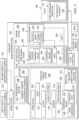
- composite manufacturing system 132 may be used to manufacture composite structure 102.
- Filler manufacturing system 134 may be part of composite manufacturing system 132.
- filler manufacturing system 134 may be the portion of composite manufacturing system 132 used to manufacture filler 108.
- Filler 108 may be manufactured in different ways using filler manufacturing system 134.
- Composite manufacturing system 132 is described in greater detail in Figure 2 below.
- Composite manufacturing system 132 may be used to manufacture filler 108 using first plurality of discontinuous filaments 122 and second plurality of discontinuous filaments 124.
- composite manufacturing system 132 may include mixing system 200, feedstock forming system 202, and shaping system 204.
- Mixing system 200 may be used to mix first plurality of discontinuous filaments 122 and second plurality of discontinuous filaments 124 together to form mixture 206.
- Mixing system 200 may mix first plurality of discontinuous filaments 122 and second plurality of discontinuous filaments 124 such that mixture 206 is a substantially homogenous mixture 208 comprised of randomly oriented discontinuous filaments 210.
- Feedstock forming system 202 may use mixture 206 to form feedstock 212.
- Feedstock forming system 202 may be implemented in different ways.
- feedstock forming system 202 may include press device 214, cutter 216, blender 218, and compressing device 220.
- Press device 214 may form sheet 222 using mixture 206.
- press device 214 may apply pressure to mixture 206 to flatten mixture 206 out to form sheet 222.
- Sheet 222 may be a thin veil of randomly oriented discontinuous filaments 210.
- Cutter 216 may be used to cut sheet 222 into plurality of strips 224.
- the strips in plurality of strips 224 may have substantially uniform shapes and sizes.
- plurality of strips 224 may be of different shapes, different sizes, or both.
- Blender 218 may be used to mix plurality of strips 224 together to form feedstock material 226.
- blender 218 may mix plurality of strips 224 at a high speed such that a wad of feedstock material 226 is formed.
- Feedstock material 226 may be substantially isotropic.
- Compressing device 220 may then be used to compress feedstock material 226 to form the final feedstock 212.
- compressing device 220 may compress feedstock material 226 with respect to three dimensions 228 at substantially constant rate 230 to form feedstock 212.
- feedstock material 226 may be compressed with respect to three dimensions 228 at substantially constant rate 230 to form feedstock 212 having selected fiber volume fraction 232.
- compression of feedstock material 226 may be performed isotatically, which may mean that equal pressure is applied to all sides of feedstock material 226.
- Selected fiber volume fraction 232 may be, for example, without limitation, between about 5 percent and 80 percent. In some cases, selected fiber volume fraction 232 may be preferably between about 20 percent and about 60 percent.
- shaping system 204 may be used to form filler structure 233 using feedstock 212.
- shaping system 204 includes cutting device 234. Cutting device 234 may be used to cut out selected portion 236 of feedstock 212.
- cutting device 234 may be used to cut away a portion of feedstock 212 such that only selected portion 236 having selected shape 238 remains.
- Selected shape 238 may be a three-dimensional shape such as, for example, without limitation, a triangular-type prism, a hexagonal-type prism, a cylindrical shape, some other type of polyhedral shape, or some other type of three-dimensional shape.
- selected portion 236 of feedstock 212 having selected shape 238 forms filler structure 233.
- number of edges 240 of selected portion 236 of feedstock 212 may need to be further shaped in order to form filler structure 233.
- Number of edges 240 may be shaped using, for example, edge shaping system 242.
- edge shaping system 242 may include number of rollers 244.
- Number of rollers 244 may be rolled along number of edges 240 to shape number of edges 240.
- Number of rollers 244 may include at least one of spherical roller 246, cylindrical roller 248, or some other type of roller.
- number of rollers 244 may be rolled along number of edges 240, while heat 250 is being applied to number of edges 240 by heating device 252, to shape number of edges 240.
- edge shaping system 242 may include mold 254.
- Mold 254 may be comprised of one or more mold pieces. Selected portion 236 of feedstock 212 may be placed into mold 254, which may shape number of edges 240.
- mold 254 may be shaped such that forcing selected portion 236 of feedstock 212 into mold 254 shapes number of edges 240. Applying heat 250 to selected portion 236 of feedstock 212, while selected portion 236 is in mold 254, may set the shape of each of number of edges 240.
- filler structure 233 may be formed in a number of different ways. Once filler structure 233 has been formed, in some illustrative examples, additional binder 130 may be injected within filler structure 233. In other illustrative examples, additional binder 130 may be added to blender 218 prior to the mixing of plurality of strips 224 to form feedstock material 226.
- Resin 116 may then be impregnated within filler structure 233 to form filler 108.
- filler 108 may be formed such that filler 108 has set of filler properties 109 that substantially match set of properties 110 of composite structure 102. Further, filler 108 is formed to reduce or prevent the development of undesired inconsistencies within filler 108.
- resin 116 may be impregnated into selected portion 236 of feedstock 212 prior to the shaping of number of edges 240. In this manner, filler structure 233 may or may not include resin 116.
- composite manufacturing system 132 may be used to manufacture composite structure 102 having filler 108 that fills void 107.
- Discontinuous filaments 120 may be used to form filler 108 having connectivity propagating in all directions with respect to three dimensions.
- Three-dimensional fiber matrix 117 comprised of discontinuous filaments 120 may be a three-dimensional network of filaments that may reduce the total amount of fiber required to support filler 108. This reduced amount of fiber may, in turn, reduce the presence of micro-cracking and enable quicker manufacturing processes. For example, it may be easier to fill void 107 between first composite part 105 and second composite part 106, which may be dry preforms, with filler 108 having a lower fiber density.
- three-dimensional fiber matrix 117 may increase the strength of and reduce the weight of filler 108. Further, filler coefficient of thermal expansion 113 may be reduced and filler coefficient of thermal expansion 113 may be equally present in all directions with respect to three dimensions.
- Filler 108 may be uniform in all directions. Consequently, filler 108 may be capable of carrying loads in all directions as needed.
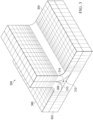
- composite structure 300 may be an example of one implementation for composite structure 102 in Figure 1 .
- composite structure 300 may include base 302, part 304, and part 306. Void 308 is created between base 302, part 304, and part 306. Void 308 may be an example of one implementation for void 107 in Figure 1 .
- filler 310 is used to substantially fill void 308.
- Filler 310 may be an example of one implementation for filler 108 in Figures 1-2 .
- Filler 108 may be comprised of fiber matrix 312.
- Fiber matrix 312 may be comprised of discontinuous filaments 314 that are randomly oriented and entangled with each other such that fiber matrix 312, and thereby filler 310, is substantially isotropic.
- Fiber matrix 312 and discontinuous filaments 314 may be examples of implementations for fiber matrix 115 and discontinuous filaments 120, respectively, in Figure 1 .
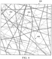
- Fiber matrix 400 may be an example of one implementation for fiber matrix 115 in Figure 1 .
- fiber matrix 400 may include discontinuous filaments 402, which may be an example of one implementation for discontinuous filaments 120 in Figure 1 .
- Discontinuous filaments 402 may include first plurality of discontinuous filaments 404 and second plurality of discontinuous filaments 406.
- First plurality of discontinuous filaments 404 and second plurality of discontinuous filaments 406 may be examples of implementations for first plurality of discontinuous filaments 122 and second plurality of discontinuous filaments 124, respectively, in Figures 1-2 .
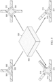
- feedstock 500 may be an example of one implementation for feedstock 212 in Figure 2 .
- Feedstock 500 may be substantially isotropic and comprised of randomly oriented discontinuous filaments 502.
- filler 504 having selected shape 505 may be formed by cutting out a selected portion from feedstock 500 and impregnating this selected portion with resin. As depicted, filler 504 may be used for filling a void within composite structure 506.
- filler 508 having selected shape 509 may be formed from feedstock 500 for use in filling a void within composite structure 510.
- filler 512 having selected shape 513 may be formed from feedstock 500 for use in filling a void within composite structure 514.
- filler 516 having selected shape 517 may be formed from feedstock 500 for use in filling a void within composite structure 518.
- Filler 504, filler 508, filler 512, and filler 516 may each be an example of one implementation for filler 108 in Figures 1-2 .
- feedstock 600 may be an example of one implementation for feedstock 212 in Figure 2 .
- Selected portion 602 may be cut out from feedstock 600 using a cutting device such as, for example, without limitation, cutting device 234 in Figure 2 .
- Selected portion 602 may be an example of one implementation for selected portion 236 in Figure 2 .
- selected portion 602 may include edge 603, edge 605, and edge 607. Resin (not shown) may then be impregnated within selected portion 602.
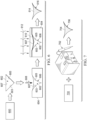
- Selected portion 602 may be pressed into cavity 606 of mold 604 by applying force 608 to edge 607 of selected portion 602.
- Cavity 606 may be shaped such that forcing selected portion 602 into cavity 606 shapes edge 603 and edge 605. Force 608 applied to edge 607 may also shape edge 607.
- Mold 604 may include plate 610 that is placed over edge 607 to maintain the desired shape for edge 607. Heat 612 may then be applied to selected portion 602 within mold 604. Heat 612 may cure selected portion 602 with resin (not shown) infused within selected portion 602 to form filler 614. Filler 614 may have final shape 616.
- feedstock 700 may be an example of one implementation for feedstock 212 in Figure 2 .
- Electronic knife 702 may be used to cut out selected portion 704 having selected shape 706 from feedstock 700.
- Electronic knife 702 may be an example of one implementation for cutting device 234 in Figure 2 .
- selected portion 800 may be an example of one implementation for selected portion 236 of feedstock 212 in Figure 2 .
- Rollers 802 may be an example of one implementation for number of rollers 244 in Figure 2 .
- Rollers 802 include spherical roller 804, spherical roller 806, and spherical roller 808.
- rollers 802 may be part of a nip roll compression system.
- Spherical roller 804 may be rotated about axis 810 in the direction of arrow 812 to shape edge 814 of selected portion 800 such that edge 814 substantially conforms to the radius of curvature of spherical roller 804.
- spherical roller 806 may be rotated about axis 816 in the direction of arrow 818 to shape edge 820 of selected portion 800 such that edge 820 substantially conforms to the radius of curvature of spherical roller 806.
- spherical roller 808 may be rotated about axis 822 in the direction of arrow 824 to shape edge 826 of selected portion 800 such that edge 826 substantially conforms to the radius of curvature of spherical roller 808.
- selected portion 900 may be an example of one implementation for selected portion 236 of feedstock 212 in Figure 2 .
- Rollers 902 may be an example of one implementation for number of rollers 244 in Figure 2 .
- rollers 902 may be part of a nip roll compression system.
- Rollers 902 include cylindrical roller 904, spherical roller 906, and spherical roller 908.
- Cylindrical roller 904 may be rotated about axis 910 in the direction of arrow 912 to shape edge 914 of selected portion 900 such that edge 914 substantially conforms to the radius of curvature of cylindrical roller 904.
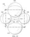
- selected portion 1000 may be an example of one implementation for selected portion 236 of feedstock 212 in Figure 2 .
- Rollers 1002 may be an example of one implementation for number of rollers 244 in Figure 2 .
- rollers 1002 may be part of a nip roll compression system.
- Rollers 1002 include spherical roller 1004, spherical roller 1006, spherical roller 1008, and spherical roller 1010.
- Spherical roller 1004, spherical roller 1006, spherical roller 1008, and spherical roller 1010 may be used to shape edge 1012, edge 1014, edge 1016, and edge 1018, respectively, of selected portion 1000.
- FIG. 3-10 may be illustrative examples of how components shown in block form in Figures 1-2 can be implemented as physical structures. Additionally, some of the components in Figures 3-10 may be combined with components in Figures 1-2 , used with components in Figures 1-2 , or a combination of the two.
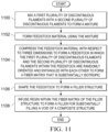
- FIG. 11 an illustration of a process for forming a filler for a void in a composite structure is depicted in the form of a flowchart in accordance with an illustrative aspect.
- the process illustrated in Figure 11 may be used to form filler 108 in Figures 1-2 .
- the process illustrated in Figure 11 may be implemented using composite manufacturing system 132 in Figures 1-2 .
- the process may begin by mixing a first plurality of discontinuous filaments with a second plurality of discontinuous filaments to form a mixture (operation 1100).
- the mixture formed in operation 1100 may be a homogenous mixture.
- the homogenous mixture may have a uniform composition and uniform properties.
- the first plurality of discontinuous filaments and the second plurality of discontinuous filaments may be substantially uniformly distributed throughout the mixture.
- feedstock material may be formed using the mixture (operation 1102). Thereafter, the feedstock material is compressed with respect to three dimensions to form a feedstock in which the first plurality of discontinuous filaments and the second plurality of discontinuous filaments within the feedstock are randomly oriented and entangled with each other to form a fiber matrix that is substantially isotropic (operation 1104).
- the feedstock may be shaped to form a filler structure (operation 1106).
- Resin may then be infused within the fiber matrix of the filler structure to form a filler for substantially filling a void of a composite structure (operation 1108), with the process terminating thereafter.
- operation 1108 is not performed.
- the filler structure formed in operation 1106 may form the final filler.
- This filler may be referred to as a dry filler.
- This dry filler may be collocated with a first dry preform and a second dry preform to form a composite structure.
- the dry filler may fill a void between the first dry preform and a second dry preform.
- Resin may then be infused into the composite structure to form a resin-infused composite structure, which may then be cured to form a fully cured and final composite structure.
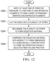
- FIG. 12 an illustration of a process for forming a feedstock is depicted in the form of a flowchart in accordance with an illustrative aspect.
- the process illustrated in Figure 12 may be an example of one manner in which operation 1102 and operation 1104 in Figure 11 may be performed. Further, this process may be implemented using, for example, without limitation, feedstock forming system 202 in Figure 2 .
- the process may begin by applying at least one of force or pressure to a mixture of discontinuous filaments to form a sheet of randomly oriented discontinuous filaments (operation 1200).
- the mixture may be the mixture formed in operation 1100 in Figure 11 .
- This mixture may be a substantially homogenous mixture.
- the sheet may then be cut into a plurality of strips (operation 1202).
- the plurality of strips may be recombined to form feedstock material (operation 1204).
- operation 1204 may be performed using a blender to blend together the plurality of strips to form feedstock material.
- the feedstock material may be compressed with respect to three dimensions at a substantially constant rate to form a feedstock having a selected fiber volume fraction (operation 1206), with the process terminating thereafter.
- the selected fiber volume fraction may be, for example, without limitation, between about 5 percent and about 60 percent.
- the feedstock material may be compressed at a substantially constant rate in directions corresponding to the three dimensions.
- FIG. 13 an illustration of a more detailed process for forming a filler for a void in a composite structure is depicted in the form of a flowchart in accordance with an illustrative aspect.
- the process illustrated in Figure 13 may be used to form filler 108 in Figures 1-2 .
- the process illustrated in Figure 11 may be implemented using composite manufacturing system 132 in Figures 1-2 .
- the process may begin by mixing a first plurality of discontinuous filaments with a second plurality of discontinuous filaments to form a substantially homogenous mixture in which the filaments are randomly oriented (operation 1300). Next, the mixture may be used to form feedstock material (operation 1302).
- the feedstock material may be compressed with respect to three dimensions to form a feedstock comprising a fiber matrix in which the first plurality of discontinuous filaments and the second plurality of discontinuous filaments are randomly oriented and entangled with each other such that the fiber matrix is substantially isotropic (operation 1304).
- the fiber matrix may be a three-dimensional fiber matrix.
- a selected portion having a selected shape may then be cut out of the feedstock (operation 1306).
- a number of edges of the selected portion of the feedstock may be shaped using at least one of a cutting device, a number of spherical rollers, a number of cylindrical rollers, a mold, a heating device, or some other type of device to form a filler structure (operation 1308).
- Resin may be infused within the filler structure to form a filler for substantially filling a void of a composite structure (operation 1310), with the process terminating thereafter.
- aircraft manufacturing and service method 1400 may be described in the context of aircraft manufacturing and service method 1400 as shown in Figure 14 and aircraft 1500 as shown in Figure 15 .
- Figure 14 an illustration of an aircraft manufacturing and service method is depicted in the form of a block diagram in accordance with an illustrative aspect.
- aircraft manufacturing and service method 1400 may include specification and design 1402 of aircraft 1500 in Figure 15 and material procurement 1404.
- aircraft 1500 in Figure 15 During production, component and subassembly manufacturing 1406 and system integration 1408 of aircraft 1500 in Figure 15 takes place. Thereafter, aircraft 1500 in Figure 15 may go through certification and delivery 1410 in order to be placed in service 1412. While in service 1412 by a customer, aircraft 1500 in Figure 15 is scheduled for routine maintenance and service 1414, which may include modification, reconfiguration, refurbishment, and other maintenance or service.
- Each of the processes of aircraft manufacturing and service method 1400 may be performed or carried out by a system integrator, a third party, and/or an operator.
- the operator may be a customer.
- a system integrator may include, without limitation, any number of aircraft manufacturers and major-system subcontractors
- a third party may include, without limitation, any number of vendors, subcontractors, and suppliers
- an operator may be an airline, a leasing company, a military entity, a service organization, and so on.
- aircraft 1500 is produced by aircraft manufacturing and service method 1400 in Figure 14 and may include airframe 1502 with plurality of systems 1504 and interior 1506.
- systems 1504 include one or more of propulsion system 1508, electrical system 1510, hydraulic system 1512, and environmental system 1514. Any number of other systems may be included.
- propulsion system 1508 include one or more of propulsion system 1508, electrical system 1510, hydraulic system 1512, and environmental system 1514. Any number of other systems may be included.
- propulsion system 1508 electrical system 1510, hydraulic system 1512, and environmental system 1514. Any number of other systems may be included.
- an aerospace example is shown, different illustrative aspects may be applied to other industries, such as the automotive industry.
- filler 108 from Figure 1 may be manufactured and used during any one of the stages of aircraft manufacturing and service method 1400.
- filler 108 from Figure 1 may be manufactured, used, or both during at least one of material procurement 1404, component and subassembly manufacturing 1406, system integration 1408, routine maintenance and service 1414, or some other stage of aircraft manufacturing and service method 1400.
- fillers, such as filler 108 from Figure 1 may be used to fill voids in composite structures that form airframe 1502 or interior 1506 of aircraft 1500.
- components or subassemblies produced in component and subassembly manufacturing 1406 in Figure 14 may be fabricated or manufactured in a manner similar to components or subassemblies produced while aircraft 1500 is in service 1412 in Figure 14 .
- one or more apparatus aspects, method aspects, or a combination thereof may be utilized during production stages, such as component and subassembly manufacturing 1406 and system integration 1408 in Figure 14 .
- One or more apparatus aspects, method aspects, or a combination thereof may be utilized while aircraft 1500 is in service 1412 and/or during maintenance and service 1414 in Figure 14 .
- the use of a number of the different illustrative aspects may substantially expedite the assembly of and/or reduce the cost of aircraft 1500.
- a fiber matrix (115) comprising:
Landscapes
- Chemical & Material Sciences (AREA)
- Engineering & Computer Science (AREA)
- Mechanical Engineering (AREA)
- Composite Materials (AREA)
- Health & Medical Sciences (AREA)
- Materials Engineering (AREA)
- Manufacturing & Machinery (AREA)
- Chemical Kinetics & Catalysis (AREA)
- Medicinal Chemistry (AREA)
- Polymers & Plastics (AREA)
- Organic Chemistry (AREA)
- Moulding By Coating Moulds (AREA)
- Reinforced Plastic Materials (AREA)
- Casting Or Compression Moulding Of Plastics Or The Like (AREA)
Claims (15)
- Appareil comprenant :une structure composite (102, 300) ayant un vide (107, 308) ; etune charge (108, 310) comprenant une matrice de fibres (115) qui est uniforme dans toutes les directions, dans lequel la matrice de fibres (115) comprend :une première pluralité de filaments discontinus (122) dans lesquels chaque filament (122) de la première pluralité de filaments discontinus (122) est constitué d'un matériau de raidissement (126) ; etune seconde pluralité de filaments discontinus (124) dans lesquels chaque filament (124) de la seconde pluralité de filaments discontinus (124) est constitué d'un matériau de liaison (128),dans lequel des filaments discontinus (120) à la fois de la première pluralité de filaments discontinus (122) et de la seconde pluralité de filaments discontinus (124) sont orientés de manière aléatoire et enchevêtrés les uns avec les autres,dans lequel la charge (108, 310) est utilisée pour remplir sensiblement le vide (107, 308) et dans lequel la charge (108, 310) a un ensemble de propriétés de charge (109) qui correspondent sensiblement à un ensemble de propriétés (110) de la structure composite (102, 300), dans lequel l'ensemble de propriétés de charge (110) comporte un coefficient de dilatation thermique (111) et une rigidité (112).
- Appareil selon la revendication 1, dans lequel le matériau de raidissement (126) comprend au moins l'un parmi du carbone, de la silice, du verre, du bore, une fibre synthétique para-aramide, un polyimide, un matériau céramique, ou un matériau métallique.
- Appareil selon la revendication 1 ou 2, dans lequel le matériau de liaison comprend (128) au moins l'un parmi un matériau thermoplastique ou un matériau thermodurcissable.
- Appareil selon l'une quelconque des revendications 1 à 3, dans lequel la charge (108, 310) comprend en outre :
une résine (116) infusée au sein de la matrice de fibres (115). - Appareil selon l'une quelconque des revendications 1 à 4, dans lequel la charge (108, 310) comprend en outre :
un liant supplémentaire (130) au sein de la matrice de fibres (115) pour renforcer la charge (108, 310). - Appareil selon l'une quelconque des revendications 1 à 5, dans lequel chacun des filaments discontinus (120) a une longueur d'au moins un millimètre environ.
- Procédé permettant de remplir sensiblement un vide (107, 308) d'une structure composite (102, 300) à l'aide d'une charge (108, 310), le procédé comprenant :
la fabrication de la charge (108, 308), comprenant :le mélange (1100) d'une première pluralité de filaments discontinus (122) avec une seconde pluralité de filaments discontinus (124) pour former un mélange (206) ;la formation (1102) d'une matière première (226) à l'aide du mélange (206) ;la compression (1104) de la matière première (226) pour former une charge d'alimentation (212) dans laquelle des filaments discontinus (120) de la première pluralité de filaments discontinus (122) et de la seconde pluralité de filaments discontinus (124) au sein de la charge d'alimentation (212) sont orientés de manière aléatoire et enchevêtrés les uns avec les autres pour former une matrice de fibres (115) qui est uniforme dans toutes les directions ; etla mise en forme (1106) de la charge d'alimentation (212) pour former une structure de charge (233) à utiliser pour former la charge (108, 310), dans lequel le mélange (1100) de la première pluralité de filaments discontinus (122) avec la seconde pluralité de filaments discontinus (124) comprend :le mélange de la première pluralité de filaments discontinus (122) constitués d'un matériau de raidissement (126) avec la seconde pluralité de filaments discontinus (124) constitués d'un matériau de liaison (128), etle remplissage sensible du vide (107, 308) de la structure composite (102, 300) avec la charge (108, 310), dans lequel la charge (108, 310) a un ensemble de propriétés de charge (109) qui correspondent sensiblement à un ensemble de propriétés (110) de la structure composite (102, 300), dans lequel l'ensemble de propriétés de charge (110) comporte un coefficient de dilatation thermique (111) et une rigidité (112). - Procédé selon la revendication 7, dans lequel le mélange (1100) de la première pluralité de filaments discontinus (122) constitués du matériau de raidissement (126) avec la seconde pluralité de filaments discontinus (124) constitués du matériau de liaison (128) comprend :
le mélange de la première pluralité de filaments discontinus (122) avec la seconde pluralité de filaments discontinus (124) pour former un mélange sensiblement homogène (208). - Procédé selon l'une quelconque des revendications 7 à 8, dans lequel la compression (1104) de la matière première (226) comprend :
la compression (1206) de la matière première (226) en trois dimensions à une vitesse sensiblement constante pour former la charge d'alimentation (212). - Procédé selon l'une quelconque des revendications 7 à 9, dans lequel la compression (1104) de la matière première (226) comprend :
la compression de la matière première (226) en trois dimensions pour former la charge d'alimentation (212) ayant une fraction volumique de fibres sélectionnée (232) comprise entre environ 5 pour cent et environ 80 pour cent, dans lequel la charge d'alimentation (212) est uniforme dans toutes les directions. - Procédé selon l'une quelconque des revendications 7 à 10, dans lequel la mise en forme (1106) de la charge d'alimentation (212) comprend :
la découpe (1306) d'une partie sélectionnée (236) de la charge d'alimentation (212) ayant une forme sélectionnée (238). - Procédé selon la revendication 11, dans lequel la mise en forme de la charge d'alimentation (212) comprend en outre :
la mise en forme d'un certain nombre de bords (240) de la partie sélectionnée (236) de la charge d'alimentation (212) pour former la structure de charge (223). - Procédé selon la revendication 12, dans lequel la mise en forme du nombre de bords de la partie sélectionnée (236) de la charge d'alimentation (212) comprend :
la mise en forme du nombre de bords (240) à l'aide d'au moins l'un parmi un certain nombre de rouleaux (244), un moule (254), ou un dispositif de chauffage (252). - Procédé selon l'une quelconque des revendications 7 à 11, comprenant en outre :
l'ajout d'un liant supplémentaire (130) dans la structure de charge (223) pour former la charge (108, 310). - Procédé selon la revendication 14, comprenant en outre :
l'imprégnation de la structure de charge (223) avec une résine (116) pour former la charge (108, 310).
Priority Applications (1)
| Application Number | Priority Date | Filing Date | Title |
|---|---|---|---|
| EP25168000.5A EP4556205A3 (fr) | 2015-07-29 | 2016-05-19 | Nouilles composées d'une matrice de filaments discontinus |
Applications Claiming Priority (1)
| Application Number | Priority Date | Filing Date | Title |
|---|---|---|---|
| US14/812,458 US20170029577A1 (en) | 2015-07-29 | 2015-07-29 | Noodle Comprised of a Matrix of Discontinuous Filaments |
Related Child Applications (2)
| Application Number | Title | Priority Date | Filing Date |
|---|---|---|---|
| EP25168000.5A Division-Into EP4556205A3 (fr) | 2015-07-29 | 2016-05-19 | Nouilles composées d'une matrice de filaments discontinus |
| EP25168000.5A Division EP4556205A3 (fr) | 2015-07-29 | 2016-05-19 | Nouilles composées d'une matrice de filaments discontinus |
Publications (2)
| Publication Number | Publication Date |
|---|---|
| EP3141377A1 EP3141377A1 (fr) | 2017-03-15 |
| EP3141377B1 true EP3141377B1 (fr) | 2025-05-07 |
Family
ID=56132744
Family Applications (2)
| Application Number | Title | Priority Date | Filing Date |
|---|---|---|---|
| EP16170468.9A Active EP3141377B1 (fr) | 2015-07-29 | 2016-05-19 | Appareil comprenant une structure composite ayant un vide et une charge et méthode pour remplir substantiellement un vide d'une structure composite |
| EP25168000.5A Pending EP4556205A3 (fr) | 2015-07-29 | 2016-05-19 | Nouilles composées d'une matrice de filaments discontinus |
Family Applications After (1)
| Application Number | Title | Priority Date | Filing Date |
|---|---|---|---|
| EP25168000.5A Pending EP4556205A3 (fr) | 2015-07-29 | 2016-05-19 | Nouilles composées d'une matrice de filaments discontinus |
Country Status (5)
| Country | Link |
|---|---|
| US (2) | US20170029577A1 (fr) |
| EP (2) | EP3141377B1 (fr) |
| CN (1) | CN106393737B (fr) |
| AU (1) | AU2016203032B2 (fr) |
| RU (1) | RU2716794C2 (fr) |
Families Citing this family (7)
| Publication number | Priority date | Publication date | Assignee | Title |
|---|---|---|---|---|
| US20170029577A1 (en) | 2015-07-29 | 2017-02-02 | The Boeing Company | Noodle Comprised of a Matrix of Discontinuous Filaments |
| US10800128B2 (en) | 2018-01-24 | 2020-10-13 | General Electric Company | Composite components having T or L-joints and methods for forming same |
| US11305859B2 (en) | 2018-03-28 | 2022-04-19 | The Boeing Company | Method for forming a composite structure |
| US11254074B2 (en) * | 2019-06-19 | 2022-02-22 | The Boeing Company | Apparatus and method for making radius composite gap filler |
| US11529776B2 (en) * | 2019-08-01 | 2022-12-20 | The Boeing Company | Aircraft comprising composite structural component, and method for forming composite structural component |
| US11504930B2 (en) * | 2021-02-03 | 2022-11-22 | General Electric Company | Compaction system and methods for compacting composite components |
| US12590544B2 (en) | 2023-11-30 | 2026-03-31 | General Electric Company | Composite airfoil |
Citations (1)
| Publication number | Priority date | Publication date | Assignee | Title |
|---|---|---|---|---|
| US5376327A (en) * | 1993-07-01 | 1994-12-27 | Automotive Polymer-Based Composites Joint Venture And Development Partnership | Method and apparatus for hermetic pneumatic rapid preforming of chopped fibers |
Family Cites Families (17)
| Publication number | Priority date | Publication date | Assignee | Title |
|---|---|---|---|---|
| US5272000A (en) * | 1987-05-22 | 1993-12-21 | Guardian Industries Corp. | Non-woven fibrous product containing natural fibers |
| NO178294C (no) * | 1989-07-24 | 1996-02-28 | Wiggins Teape Group Ltd | Fremgangsmåte for fremstilling av et luftpermeabelt ark av glassfiberarmert, termoplastisk materiale |
| US5579609A (en) | 1994-06-10 | 1996-12-03 | Tracor, Inc. | Rigidizable inflatable structure |
| US5810562A (en) * | 1996-09-17 | 1998-09-22 | Sikorsky Aircraft Corporation | Composite rotating swashplate for a helicopter rotor system |
| AU2001262912A1 (en) | 2000-02-25 | 2001-09-03 | The Boeing Company | Laminated composite radius filler |
| SE0001929L (sv) * | 2000-05-23 | 2001-12-21 | Christian Hoegfors | Förfarande för framställning av en härdplastinnehållande fiberbana, en sådan fiberbana, och en armerad härdplastkomposit innefattande fiberbanan |
| ES2304843B1 (es) * | 2006-04-25 | 2009-10-29 | Serra Soldadura S.A. | Metodo y aparato para fabricacion de perfiles macizos a partir de banda de fibra preimpregnada con resina. |
| US8540833B2 (en) | 2008-05-16 | 2013-09-24 | The Boeing Company | Reinforced stiffeners and method for making the same |
| US20120074265A1 (en) * | 2009-06-11 | 2012-03-29 | Saab Ab | Nano-reinforced radius filler for an aircraft structure and a method of producing an aircraft structure comprising such filler |
| EP2343046A1 (fr) * | 2010-01-08 | 2011-07-13 | Nirvana's Tree House B.V. | Copolymères triblocs fonctionnalisés et compositions contenant lesdits polymères |
| US8591685B2 (en) * | 2011-10-27 | 2013-11-26 | The Boeing Company | Method and apparatus for producing composite fillers |
| EP2610165B1 (fr) | 2011-12-28 | 2017-02-08 | AIRBUS HELICOPTERS DEUTSCHLAND GmbH | Agent de remplissage de gousset composite et procédé de fabrication de cet agent de remplissage de gousset composite |
| EP2666622B1 (fr) * | 2012-05-22 | 2017-04-12 | AIRBUS HELICOPTERS DEUTSCHLAND GmbH | Ensemble de transition peau-raidisseur, procédé de fabrication et d'application dudit ensemble de transition peau-raidisseur |
| US9370921B2 (en) * | 2012-11-01 | 2016-06-21 | The Boeing Company | Composite radius fillers and methods of forming the same |
| US9463880B2 (en) * | 2013-02-07 | 2016-10-11 | The Boeing Company | Method and system of making composite structures having gap fillers with chopped fiber material |
| US9358764B2 (en) * | 2013-12-17 | 2016-06-07 | The Boeing Company | System and method of joining components |
| US20170029577A1 (en) | 2015-07-29 | 2017-02-02 | The Boeing Company | Noodle Comprised of a Matrix of Discontinuous Filaments |
-
2015
- 2015-07-29 US US14/812,458 patent/US20170029577A1/en not_active Abandoned
-
2016
- 2016-05-11 AU AU2016203032A patent/AU2016203032B2/en active Active
- 2016-05-16 RU RU2016118819A patent/RU2716794C2/ru active
- 2016-05-19 EP EP16170468.9A patent/EP3141377B1/fr active Active
- 2016-05-19 EP EP25168000.5A patent/EP4556205A3/fr active Pending
- 2016-07-28 CN CN201610605799.6A patent/CN106393737B/zh active Active
-
2019
- 2019-12-17 US US16/718,086 patent/US11427687B2/en active Active
Patent Citations (1)
| Publication number | Priority date | Publication date | Assignee | Title |
|---|---|---|---|---|
| US5376327A (en) * | 1993-07-01 | 1994-12-27 | Automotive Polymer-Based Composites Joint Venture And Development Partnership | Method and apparatus for hermetic pneumatic rapid preforming of chopped fibers |
Also Published As
| Publication number | Publication date |
|---|---|
| AU2016203032B2 (en) | 2021-04-22 |
| RU2716794C2 (ru) | 2020-03-16 |
| CN106393737B (zh) | 2021-02-26 |
| US11427687B2 (en) | 2022-08-30 |
| AU2016203032A1 (en) | 2017-02-16 |
| CN106393737A (zh) | 2017-02-15 |
| US20170029577A1 (en) | 2017-02-02 |
| US20210253807A1 (en) | 2021-08-19 |
| RU2016118819A3 (fr) | 2019-08-27 |
| RU2016118819A (ru) | 2017-11-21 |
| EP4556205A3 (fr) | 2025-08-13 |
| EP3141377A1 (fr) | 2017-03-15 |
| EP4556205A2 (fr) | 2025-05-21 |
Similar Documents
| Publication | Publication Date | Title |
|---|---|---|
| EP3141377B1 (fr) | Appareil comprenant une structure composite ayant un vide et une charge et méthode pour remplir substantiellement un vide d'une structure composite | |
| AU2020201610B2 (en) | Fabrication of composite laminates using temporarily stitched preforms | |
| JP6966848B2 (ja) | 補強材を有する複合構造体及びその製造方法 | |
| EP2764987B1 (fr) | Procédé et système de fabrication de structures composites comprenant des matériaux de remplissage avec un matériau de fibres coupées | |
| US20190299552A1 (en) | Textured caul plate | |
| US9272495B1 (en) | Compaction system for composite stringers | |
| AU2014274534B2 (en) | Three-dimensional filament network for a composite laminate | |
| US9994008B2 (en) | Method and system for compacting composite part layup utilizing a single release film layer | |
| US20170182738A1 (en) | Composite Filler | |
| US20240269955A1 (en) | Foam sheeting for honeycomb core walls, to replace paper and metal honeycomb and machined foam core in sandwich structure | |
| US20210023798A1 (en) | Permeable radius filler for composite structure | |
| CN104428578A (zh) | 具有带有软化带的接头的复合罐及制造该罐的方法 | |
| JP6368748B2 (ja) | 繊維強化樹脂を成形する成形加工方法 | |
| US10899084B2 (en) | Methods for forming composite structures | |
| CN112743921B (zh) | 具有熔渗膜的复合材料系统和方法 | |
| CN104470706B (zh) | 用于控制低温下接头中的应力的装置及其制备方法 | |
| US20230202138A1 (en) | Thermoplastic Joining Films and Methods for Joining Thermoplastic and Thermoset Composite Materials | |
| EP3564016B1 (fr) | Panneau composite comportant plusieurs peaux et un noyau |
Legal Events
| Date | Code | Title | Description |
|---|---|---|---|
| PUAI | Public reference made under article 153(3) epc to a published international application that has entered the european phase |
Free format text: ORIGINAL CODE: 0009012 |
|
| STAA | Information on the status of an ep patent application or granted ep patent |
Free format text: STATUS: REQUEST FOR EXAMINATION WAS MADE |
|
| 17P | Request for examination filed |
Effective date: 20160519 |
|
| AK | Designated contracting states |
Kind code of ref document: A1 Designated state(s): AL AT BE BG CH CY CZ DE DK EE ES FI FR GB GR HR HU IE IS IT LI LT LU LV MC MK MT NL NO PL PT RO RS SE SI SK SM TR |
|
| AX | Request for extension of the european patent |
Extension state: BA ME |
|
| RBV | Designated contracting states (corrected) |
Designated state(s): AL AT BE BG CH CY CZ DE DK EE ES FI FR GB GR HR HU IE IS IT LI LT LU LV MC MK MT NL NO PL PT RO RS SE SI SK SM TR |
|
| STAA | Information on the status of an ep patent application or granted ep patent |
Free format text: STATUS: EXAMINATION IS IN PROGRESS |
|
| 17Q | First examination report despatched |
Effective date: 20190823 |
|
| RAP3 | Party data changed (applicant data changed or rights of an application transferred) |
Owner name: THE BOEING COMPANY |
|
| GRAP | Despatch of communication of intention to grant a patent |
Free format text: ORIGINAL CODE: EPIDOSNIGR1 |
|
| STAA | Information on the status of an ep patent application or granted ep patent |
Free format text: STATUS: GRANT OF PATENT IS INTENDED |
|
| INTG | Intention to grant announced |
Effective date: 20240829 |
|
| GRAJ | Information related to disapproval of communication of intention to grant by the applicant or resumption of examination proceedings by the epo deleted |
Free format text: ORIGINAL CODE: EPIDOSDIGR1 |
|
| STAA | Information on the status of an ep patent application or granted ep patent |
Free format text: STATUS: EXAMINATION IS IN PROGRESS |
|
| GRAP | Despatch of communication of intention to grant a patent |
Free format text: ORIGINAL CODE: EPIDOSNIGR1 |
|
| STAA | Information on the status of an ep patent application or granted ep patent |
Free format text: STATUS: GRANT OF PATENT IS INTENDED |
|
| P01 | Opt-out of the competence of the unified patent court (upc) registered |
Free format text: CASE NUMBER: APP_61517/2024 Effective date: 20241118 |
|
| INTC | Intention to grant announced (deleted) | ||
| INTG | Intention to grant announced |
Effective date: 20241223 |
|
| GRAS | Grant fee paid |
Free format text: ORIGINAL CODE: EPIDOSNIGR3 |
|
| GRAA | (expected) grant |
Free format text: ORIGINAL CODE: 0009210 |
|
| STAA | Information on the status of an ep patent application or granted ep patent |
Free format text: STATUS: THE PATENT HAS BEEN GRANTED |
|
| AK | Designated contracting states |
Kind code of ref document: B1 Designated state(s): AL AT BE BG CH CY CZ DE DK EE ES FI FR GB GR HR HU IE IS IT LI LT LU LV MC MK MT NL NO PL PT RO RS SE SI SK SM TR |
|
| REG | Reference to a national code |
Ref country code: GB Ref legal event code: FG4D |
|
| REG | Reference to a national code |
Ref country code: CH Ref legal event code: EP |
|
| REG | Reference to a national code |
Ref country code: DE Ref legal event code: R096 Ref document number: 602016092134 Country of ref document: DE |
|
| REG | Reference to a national code |
Ref country code: IE Ref legal event code: FG4D |
|
| PGFP | Annual fee paid to national office [announced via postgrant information from national office to epo] |
Ref country code: DE Payment date: 20250529 Year of fee payment: 10 |
|
| PGFP | Annual fee paid to national office [announced via postgrant information from national office to epo] |
Ref country code: GB Payment date: 20250527 Year of fee payment: 10 |
|
| PGFP | Annual fee paid to national office [announced via postgrant information from national office to epo] |
Ref country code: FR Payment date: 20250526 Year of fee payment: 10 |
|
| REG | Reference to a national code |
Ref country code: NL Ref legal event code: MP Effective date: 20250507 |
|
| PG25 | Lapsed in a contracting state [announced via postgrant information from national office to epo] |
Ref country code: FI Free format text: LAPSE BECAUSE OF FAILURE TO SUBMIT A TRANSLATION OF THE DESCRIPTION OR TO PAY THE FEE WITHIN THE PRESCRIBED TIME-LIMIT Effective date: 20250507 Ref country code: PT Free format text: LAPSE BECAUSE OF FAILURE TO SUBMIT A TRANSLATION OF THE DESCRIPTION OR TO PAY THE FEE WITHIN THE PRESCRIBED TIME-LIMIT Effective date: 20250908 Ref country code: ES Free format text: LAPSE BECAUSE OF FAILURE TO SUBMIT A TRANSLATION OF THE DESCRIPTION OR TO PAY THE FEE WITHIN THE PRESCRIBED TIME-LIMIT Effective date: 20250507 |
|
| REG | Reference to a national code |
Ref country code: LT Ref legal event code: MG9D |
|
| PG25 | Lapsed in a contracting state [announced via postgrant information from national office to epo] |
Ref country code: NO Free format text: LAPSE BECAUSE OF FAILURE TO SUBMIT A TRANSLATION OF THE DESCRIPTION OR TO PAY THE FEE WITHIN THE PRESCRIBED TIME-LIMIT Effective date: 20250807 Ref country code: GR Free format text: LAPSE BECAUSE OF FAILURE TO SUBMIT A TRANSLATION OF THE DESCRIPTION OR TO PAY THE FEE WITHIN THE PRESCRIBED TIME-LIMIT Effective date: 20250808 |
|
| PG25 | Lapsed in a contracting state [announced via postgrant information from national office to epo] |
Ref country code: NL Free format text: LAPSE BECAUSE OF FAILURE TO SUBMIT A TRANSLATION OF THE DESCRIPTION OR TO PAY THE FEE WITHIN THE PRESCRIBED TIME-LIMIT Effective date: 20250507 Ref country code: PL Free format text: LAPSE BECAUSE OF FAILURE TO SUBMIT A TRANSLATION OF THE DESCRIPTION OR TO PAY THE FEE WITHIN THE PRESCRIBED TIME-LIMIT Effective date: 20250507 |
|
| REG | Reference to a national code |
Ref country code: AT Ref legal event code: MK05 Ref document number: 1792025 Country of ref document: AT Kind code of ref document: T Effective date: 20250507 |
|
| PG25 | Lapsed in a contracting state [announced via postgrant information from national office to epo] |
Ref country code: BG Free format text: LAPSE BECAUSE OF FAILURE TO SUBMIT A TRANSLATION OF THE DESCRIPTION OR TO PAY THE FEE WITHIN THE PRESCRIBED TIME-LIMIT Effective date: 20250507 |
|
| PG25 | Lapsed in a contracting state [announced via postgrant information from national office to epo] |
Ref country code: HR Free format text: LAPSE BECAUSE OF FAILURE TO SUBMIT A TRANSLATION OF THE DESCRIPTION OR TO PAY THE FEE WITHIN THE PRESCRIBED TIME-LIMIT Effective date: 20250507 |
|
| PG25 | Lapsed in a contracting state [announced via postgrant information from national office to epo] |
Ref country code: AT Free format text: LAPSE BECAUSE OF FAILURE TO SUBMIT A TRANSLATION OF THE DESCRIPTION OR TO PAY THE FEE WITHIN THE PRESCRIBED TIME-LIMIT Effective date: 20250507 |
|
| PG25 | Lapsed in a contracting state [announced via postgrant information from national office to epo] |
Ref country code: RS Free format text: LAPSE BECAUSE OF FAILURE TO SUBMIT A TRANSLATION OF THE DESCRIPTION OR TO PAY THE FEE WITHIN THE PRESCRIBED TIME-LIMIT Effective date: 20250807 |
|
| PG25 | Lapsed in a contracting state [announced via postgrant information from national office to epo] |
Ref country code: IS Free format text: LAPSE BECAUSE OF FAILURE TO SUBMIT A TRANSLATION OF THE DESCRIPTION OR TO PAY THE FEE WITHIN THE PRESCRIBED TIME-LIMIT Effective date: 20250907 |
|
| PG25 | Lapsed in a contracting state [announced via postgrant information from national office to epo] |
Ref country code: LV Free format text: LAPSE BECAUSE OF FAILURE TO SUBMIT A TRANSLATION OF THE DESCRIPTION OR TO PAY THE FEE WITHIN THE PRESCRIBED TIME-LIMIT Effective date: 20250507 |
|
| REG | Reference to a national code |
Ref country code: CH Ref legal event code: H13 Free format text: ST27 STATUS EVENT CODE: U-0-0-H10-H13 (AS PROVIDED BY THE NATIONAL OFFICE) Effective date: 20251223 |
|
| PG25 | Lapsed in a contracting state [announced via postgrant information from national office to epo] |
Ref country code: SM Free format text: LAPSE BECAUSE OF FAILURE TO SUBMIT A TRANSLATION OF THE DESCRIPTION OR TO PAY THE FEE WITHIN THE PRESCRIBED TIME-LIMIT Effective date: 20250507 Ref country code: DK Free format text: LAPSE BECAUSE OF FAILURE TO SUBMIT A TRANSLATION OF THE DESCRIPTION OR TO PAY THE FEE WITHIN THE PRESCRIBED TIME-LIMIT Effective date: 20250507 |
|
| PG25 | Lapsed in a contracting state [announced via postgrant information from national office to epo] |
Ref country code: LU Free format text: LAPSE BECAUSE OF NON-PAYMENT OF DUE FEES Effective date: 20250519 |
|
| PG25 | Lapsed in a contracting state [announced via postgrant information from national office to epo] |
Ref country code: CH Free format text: LAPSE BECAUSE OF NON-PAYMENT OF DUE FEES Effective date: 20250531 |
|
| PG25 | Lapsed in a contracting state [announced via postgrant information from national office to epo] |
Ref country code: CZ Free format text: LAPSE BECAUSE OF FAILURE TO SUBMIT A TRANSLATION OF THE DESCRIPTION OR TO PAY THE FEE WITHIN THE PRESCRIBED TIME-LIMIT Effective date: 20250507 |
|
| PG25 | Lapsed in a contracting state [announced via postgrant information from national office to epo] |
Ref country code: EE Free format text: LAPSE BECAUSE OF FAILURE TO SUBMIT A TRANSLATION OF THE DESCRIPTION OR TO PAY THE FEE WITHIN THE PRESCRIBED TIME-LIMIT Effective date: 20250507 |
|
| PG25 | Lapsed in a contracting state [announced via postgrant information from national office to epo] |
Ref country code: SK Free format text: LAPSE BECAUSE OF FAILURE TO SUBMIT A TRANSLATION OF THE DESCRIPTION OR TO PAY THE FEE WITHIN THE PRESCRIBED TIME-LIMIT Effective date: 20250507 Ref country code: RO Free format text: LAPSE BECAUSE OF FAILURE TO SUBMIT A TRANSLATION OF THE DESCRIPTION OR TO PAY THE FEE WITHIN THE PRESCRIBED TIME-LIMIT Effective date: 20250507 |
|
| PG25 | Lapsed in a contracting state [announced via postgrant information from national office to epo] |
Ref country code: IT Free format text: LAPSE BECAUSE OF FAILURE TO SUBMIT A TRANSLATION OF THE DESCRIPTION OR TO PAY THE FEE WITHIN THE PRESCRIBED TIME-LIMIT Effective date: 20250507 |
|
| REG | Reference to a national code |
Ref country code: BE Ref legal event code: MM Effective date: 20250531 |
|
| REG | Reference to a national code |
Ref country code: DE Ref legal event code: R097 Ref document number: 602016092134 Country of ref document: DE |
|
| PG25 | Lapsed in a contracting state [announced via postgrant information from national office to epo] |
Ref country code: MC Free format text: LAPSE BECAUSE OF FAILURE TO SUBMIT A TRANSLATION OF THE DESCRIPTION OR TO PAY THE FEE WITHIN THE PRESCRIBED TIME-LIMIT Effective date: 20250507 |
|
| PLBE | No opposition filed within time limit |
Free format text: ORIGINAL CODE: 0009261 |
|
| STAA | Information on the status of an ep patent application or granted ep patent |
Free format text: STATUS: NO OPPOSITION FILED WITHIN TIME LIMIT |
|
| REG | Reference to a national code |
Ref country code: CH Ref legal event code: L10 Free format text: ST27 STATUS EVENT CODE: U-0-0-L10-L00 (AS PROVIDED BY THE NATIONAL OFFICE) Effective date: 20260318 |
|
| PG25 | Lapsed in a contracting state [announced via postgrant information from national office to epo] |
Ref country code: IE Free format text: LAPSE BECAUSE OF NON-PAYMENT OF DUE FEES Effective date: 20250519 |
|
| 26N | No opposition filed |
Effective date: 20260210 |
|
| PG25 | Lapsed in a contracting state [announced via postgrant information from national office to epo] |
Ref country code: BE Free format text: LAPSE BECAUSE OF NON-PAYMENT OF DUE FEES Effective date: 20250531 |