EP3141393A1 - Tintenstrahlaufzeichnungsvorrichtung - Google Patents
Tintenstrahlaufzeichnungsvorrichtung Download PDFInfo
- Publication number
- EP3141393A1 EP3141393A1 EP16186833.6A EP16186833A EP3141393A1 EP 3141393 A1 EP3141393 A1 EP 3141393A1 EP 16186833 A EP16186833 A EP 16186833A EP 3141393 A1 EP3141393 A1 EP 3141393A1
- Authority
- EP
- European Patent Office
- Prior art keywords
- paper sheet
- floating
- image
- unit
- inkjet recording
- Prior art date
- Legal status (The legal status is an assumption and is not a legal conclusion. Google has not performed a legal analysis and makes no representation as to the accuracy of the status listed.)
- Granted
Links
Images


















Classifications
-
- B—PERFORMING OPERATIONS; TRANSPORTING
- B41—PRINTING; LINING MACHINES; TYPEWRITERS; STAMPS
- B41J—TYPEWRITERS; SELECTIVE PRINTING MECHANISMS, i.e. MECHANISMS PRINTING OTHERWISE THAN FROM A FORME; CORRECTION OF TYPOGRAPHICAL ERRORS
- B41J13/00—Devices or arrangements of selective printing mechanisms, e.g. ink-jet printers or thermal printers, specially adapted for supporting or handling copy material in short lengths, e.g. sheets
- B41J13/0009—Devices or arrangements of selective printing mechanisms, e.g. ink-jet printers or thermal printers, specially adapted for supporting or handling copy material in short lengths, e.g. sheets control of the transport of the copy material
-
- H—ELECTRICITY
- H04—ELECTRIC COMMUNICATION TECHNIQUE
- H04N—PICTORIAL COMMUNICATION, e.g. TELEVISION
- H04N1/00—Scanning, transmission or reproduction of documents or the like, e.g. facsimile transmission; Details thereof
- H04N1/00002—Diagnosis, testing or measuring; Detecting, analysing or monitoring not otherwise provided for
- H04N1/00007—Diagnosis, testing or measuring; Detecting, analysing or monitoring not otherwise provided for relating to particular apparatus or devices
- H04N1/00013—Reading apparatus
-
- B—PERFORMING OPERATIONS; TRANSPORTING
- B41—PRINTING; LINING MACHINES; TYPEWRITERS; STAMPS
- B41J—TYPEWRITERS; SELECTIVE PRINTING MECHANISMS, i.e. MECHANISMS PRINTING OTHERWISE THAN FROM A FORME; CORRECTION OF TYPOGRAPHICAL ERRORS
- B41J11/00—Devices or arrangements of selective printing mechanisms, e.g. ink-jet printers or thermal printers, for supporting or handling copy material in sheet or web form
- B41J11/0095—Detecting means for copy material, e.g. for detecting or sensing presence of copy material or its leading or trailing end
-
- B—PERFORMING OPERATIONS; TRANSPORTING
- B41—PRINTING; LINING MACHINES; TYPEWRITERS; STAMPS
- B41J—TYPEWRITERS; SELECTIVE PRINTING MECHANISMS, i.e. MECHANISMS PRINTING OTHERWISE THAN FROM A FORME; CORRECTION OF TYPOGRAPHICAL ERRORS
- B41J2/00—Typewriters or selective printing mechanisms characterised by the printing or marking process for which they are designed
- B41J2/005—Typewriters or selective printing mechanisms characterised by the printing or marking process for which they are designed characterised by bringing liquid or particles selectively into contact with a printing material
- B41J2/01—Ink jet
-
- B—PERFORMING OPERATIONS; TRANSPORTING
- B41—PRINTING; LINING MACHINES; TYPEWRITERS; STAMPS
- B41J—TYPEWRITERS; SELECTIVE PRINTING MECHANISMS, i.e. MECHANISMS PRINTING OTHERWISE THAN FROM A FORME; CORRECTION OF TYPOGRAPHICAL ERRORS
- B41J2/00—Typewriters or selective printing mechanisms characterised by the printing or marking process for which they are designed
- B41J2/005—Typewriters or selective printing mechanisms characterised by the printing or marking process for which they are designed characterised by bringing liquid or particles selectively into contact with a printing material
- B41J2/01—Ink jet
- B41J2/135—Nozzles
- B41J2/165—Prevention or detection of nozzle clogging, e.g. cleaning, capping or moistening for nozzles
- B41J2/16579—Detection means therefor, e.g. for nozzle clogging
-
- B—PERFORMING OPERATIONS; TRANSPORTING
- B41—PRINTING; LINING MACHINES; TYPEWRITERS; STAMPS
- B41J—TYPEWRITERS; SELECTIVE PRINTING MECHANISMS, i.e. MECHANISMS PRINTING OTHERWISE THAN FROM A FORME; CORRECTION OF TYPOGRAPHICAL ERRORS
- B41J25/00—Actions or mechanisms not otherwise provided for
- B41J25/304—Bodily-movable mechanisms for print heads or carriages movable towards or from paper surface
- B41J25/308—Bodily-movable mechanisms for print heads or carriages movable towards or from paper surface with print gap adjustment mechanisms
-
- B—PERFORMING OPERATIONS; TRANSPORTING
- B65—CONVEYING; PACKING; STORING; HANDLING THIN OR FILAMENTARY MATERIAL
- B65H—HANDLING THIN OR FILAMENTARY MATERIAL, e.g. SHEETS, WEBS, CABLES
- B65H7/00—Controlling article feeding, separating, pile-advancing, or associated apparatus, to take account of incorrect feeding, absence of articles, or presence of faulty articles
- B65H7/02—Controlling article feeding, separating, pile-advancing, or associated apparatus, to take account of incorrect feeding, absence of articles, or presence of faulty articles by feelers or detectors
- B65H7/14—Controlling article feeding, separating, pile-advancing, or associated apparatus, to take account of incorrect feeding, absence of articles, or presence of faulty articles by feelers or detectors by photoelectric feelers or detectors
-
- G—PHYSICS
- G01—MEASURING; TESTING
- G01N—INVESTIGATING OR ANALYSING MATERIALS BY DETERMINING THEIR CHEMICAL OR PHYSICAL PROPERTIES
- G01N21/00—Investigating or analysing materials by the use of optical means, i.e. using sub-millimetre waves, infrared, visible or ultraviolet light
- G01N21/84—Systems specially adapted for particular applications
- G01N21/88—Investigating the presence of flaws or contamination
- G01N21/89—Investigating the presence of flaws or contamination in moving material, e.g. running paper or textiles
-
- B—PERFORMING OPERATIONS; TRANSPORTING
- B41—PRINTING; LINING MACHINES; TYPEWRITERS; STAMPS
- B41J—TYPEWRITERS; SELECTIVE PRINTING MECHANISMS, i.e. MECHANISMS PRINTING OTHERWISE THAN FROM A FORME; CORRECTION OF TYPOGRAPHICAL ERRORS
- B41J25/00—Actions or mechanisms not otherwise provided for
- B41J2025/008—Actions or mechanisms not otherwise provided for comprising a plurality of print heads placed around a drum
-
- B—PERFORMING OPERATIONS; TRANSPORTING
- B65—CONVEYING; PACKING; STORING; HANDLING THIN OR FILAMENTARY MATERIAL
- B65H—HANDLING THIN OR FILAMENTARY MATERIAL, e.g. SHEETS, WEBS, CABLES
- B65H2553/00—Sensing or detecting means
- B65H2553/40—Sensing or detecting means using optical, e.g. photographic, elements
- B65H2553/41—Photoelectric detectors
- B65H2553/412—Photoelectric detectors in barrier arrangements, i.e. emitter facing a receptor element
-
- G—PHYSICS
- G01—MEASURING; TESTING
- G01N—INVESTIGATING OR ANALYSING MATERIALS BY DETERMINING THEIR CHEMICAL OR PHYSICAL PROPERTIES
- G01N21/00—Investigating or analysing materials by the use of optical means, i.e. using sub-millimetre waves, infrared, visible or ultraviolet light
- G01N21/84—Systems specially adapted for particular applications
- G01N21/86—Investigating moving sheets
- G01N2021/8663—Paper, e.g. gloss, moisture content
-
- G—PHYSICS
- G01—MEASURING; TESTING
- G01N—INVESTIGATING OR ANALYSING MATERIALS BY DETERMINING THEIR CHEMICAL OR PHYSICAL PROPERTIES
- G01N21/00—Investigating or analysing materials by the use of optical means, i.e. using sub-millimetre waves, infrared, visible or ultraviolet light
- G01N21/84—Systems specially adapted for particular applications
- G01N21/88—Investigating the presence of flaws or contamination
- G01N21/89—Investigating the presence of flaws or contamination in moving material, e.g. running paper or textiles
- G01N21/892—Investigating the presence of flaws or contamination in moving material, e.g. running paper or textiles characterised by the flaw, defect or object feature examined
- G01N2021/8924—Dents; Relief flaws
Definitions
- the present invention relates to an inkjet recording apparatus which records an image on a paper sheet conveyed through a fixed conveying path by an inkjet method.
- paper sheets need to be conveyed in a flat state.
- floating such as wrinkles and folding
- the paper sheet may contact inkjet heads, and the inkjet heads may be damaged in the worst case.
- floating of the paper sheet is detected on the upstream side of an inkjet recording unit.
- conveyance of the paper sheet is stopped to prevent the paper sheet from contacting the inkjet heads (see, for example, Japanese Patent Application Laid-Open No. 2010-076872 ).
- an operator visually confirms a floating generation status and performs adjustment of a paper feeding system or a conveyance system in accordance with the type of the generated floating.
- the present invention has been made in consideration of such circumstances, and it is therefore an object of the present invention to provide an inkjet recording apparatus which can easily identify the type of floating when the floating is generated in a paper sheet during conveyance.
- the type of the floating when floating is generated in a paper sheet during conveyance, the type of the floating can easily be identified.
- Fig. 1 is a schematic configuration view of an inkjet recording apparatus.
- An inkjet recording apparatus 100 illustrated in Fig. 1 is a sheet-fed color inkjet recording apparatus which uses ink of four colors including cyan (C), magenta (M), yellow (Y), and black (K) to record a color image on a sheet by an inkjet method.
- the inkjet recording apparatus 100 of the present embodiment is an inkjet recording apparatus which uses general-purpose printing paper as the paper sheet and water-based ink as the ink.
- the general-purpose printing paper does not refer to so-called inkjet dedicated paper sheets but refers to paper sheets mainly made of cellulose, such as coated paper, which are used in general offset printing machines and the like.
- the paper sheets include art paper, coated paper, lightweight coated paper, cast paper, and fine coated paper.
- the water-based ink refers to the ink made by dissolving or dispersing colorants, such as dyes and paints, into water and solvents soluble in water.
- the inkjet recording apparatus 100 includes: a paper feeding unit 110 which feeds paper sheets P; a treatment liquid coating unit 120 which coats the paper sheets P fed from the paper feeding unit 110 with a treatment liquid; a treatment liquid drying unit 130 which performs dry processing of the paper sheets P coated with the treatment liquid; an inkjet recording unit 140 which performs recording on the dry-processed paper sheets P by the inkjet method; an ink drying unit 150 which performs dry processing of the paper sheets P with an image recorded thereon; and a stacking unit 160 which stacks the dry-processed paper sheets P.
- the paper feeding unit 110 feeds the paper sheets P. As illustrated in Fig. 1 , the paper feeding unit 110 includes a paper feeder 112, a feeder board 114, and a feeding drum 116.
- the paper feeder 112 takes out paper sheets P, which are set at a specified position in a bundle state, one sheet at a time in order from the top sheet and feeds the taken-out paper sheets P to the feeder board 114.
- the paper feeder 112 includes a blower which is not illustrated.
- the blower blows air to the paper sheet bundle for separating the respective paper sheets P. Volume of the air blowing out of the blower is adjustable and is adjusted as necessary.
- the feeder board 114 receives a paper sheet P supplied from the paper feeder 112, and feeds the paper sheet P to the feeding drum 116.
- the feeder board 114 includes a runner wheel 114A, a front plate 114B, and a retainer 114C.
- the runner wheel 114A is a member for pressing the paper sheet P to be conveyed with the feeder board 114.
- the runner wheel 114A which includes a plurality of rollers, depresses the paper sheet P with the rollers so as to press the paper sheet P to the feeder board 114.
- the position of the runner wheel 114A is adjustable, so that a placement position of the runner wheel 114A is adjusted as necessary.
- the front plate 114B is a member for correcting the posture of the paper sheet P conveyed to an end position of the feeder board 114.
- the front plate 114B is driven by a motor, which is not illustrated, to oscillate and appear on a conveying path of the paper sheet P.
- the retainer 114C is a member for sending the paper sheet P conveyed to the end position of the feeder board 114 to the feeding drum 116 while pressing the paper sheet P.
- the retainer 114C is driven by a motor, which is not illustrated, to oscillate in an anteroposterior direction, and the oscillating motions thereof depress the paper sheet P and sends the paper sheet P forward.
- the position of the retainer 114C is adjustable, so that a placement position of the retainer 114C is adjusted as necessary.
- the feeding drum 116 receives the paper sheet P from the feeder board 114, and transports it to the treatment liquid coating unit 120.
- the feeding drum 116 grips and rotates the tip of the paper sheet P with a gripper provided on a peripheral surface of the feeding drum 116, so that the paper sheet P is conveyed while being wound around the peripheral surface.
- the configuration of the paper feeding unit 110 is as described above.
- the paper sheets P are fed one sheet at a time to the feeder board 114 from the paper feeder 112, and are fed to the feeding drum 116 with the feeder board 114.
- Each of the fed paper sheets P is then transported to the treatment liquid coating unit 120 by the feeding drum 116.
- the treatment liquid coating unit 120 coats the paper sheet P with a treatment liquid.
- the treatment liquid is composed of a liquid having a function of condensing, insolubilizing, or thickening a coloring material component in the ink.
- the treatment liquid coating unit 120 includes a treatment liquid coating drum 122 which conveys the paper sheet P, and a treatment liquid coater 124 which coats a recording surface of the paper sheet P, which is conveyed by the treatment liquid coating drum 122, with the treatment liquid.
- the treatment liquid coating drum 122 receives the paper sheet P from the feeding drum 116, and transports it to the treatment liquid drying unit 130.
- the treatment liquid coating drum 122 grips and rotates the tip of the paper sheet P with a gripper provided on a peripheral surface of the treatment liquid coating drum 122, so that the paper sheet P is conveyed while being wound around the peripheral surface.
- the treatment liquid coater 124 coats the paper sheet P, which is conveyed by the treatment liquid coating drum 122, with the treatment liquid.
- the treatment liquid is roller-coated. That is, a roller having the treatment liquid applied to a peripheral surface thereof is pressed against the paper sheet P, which is conveyed by the treatment liquid coating drum 122, so as to coat the paper sheet P with the treatment liquid.
- the method for coating with the treatment liquid is not limited thereto, and other methods, such as a coating method using inkjet heads and a coating method using a spray, may also be adopted.
- the configuration of the treatment liquid coating unit 120 is as described above.
- the paper sheet P is coated with the treatment liquid by the treatment liquid coater 124 in the process of being conveyed by the treatment liquid coating drum 122.
- the treatment liquid drying unit 130 performs dry processing of the paper sheet P coated with the treatment liquid.
- the treatment liquid drying unit 130 includes a treatment liquid drying drum 132 which conveys the paper sheet P, and a treatment liquid dryer 134 which blows warm air to the paper sheet P, which is conveyed by the treatment liquid drying drum 132, to dry the paper sheet P.
- the treatment liquid drying drum 132 receives the paper sheet P from the treatment liquid coating drum 122 of the treatment liquid coating unit 120, and transports it to the inkjet recording unit 140.
- the treatment liquid drying drum 132 which is configured with a frame constructed into a cylindrical form, grips and rotates the tip of the paper sheet P with a gripper provided on a peripheral surface of the treatment liquid drying drum 132, so that the paper sheet P is conveyed while being wound around the peripheral surface.
- the treatment liquid dryer 134 which is placed inside the treatment liquid drying drum 132, sends warm air toward the paper sheet P conveyed by the treatment liquid drying drum 132.
- the configuration of the treatment liquid drying unit 130 is as described above.
- the paper sheet P is dry-processed by being exposed to the warm air sent from the treatment liquid dryer 134 in a process of being conveyed by the treatment liquid drying drum 132.
- the inkjet recording unit 140 records a color image on the recording surface of the paper sheet P with ink of four colors including cyan (C), magenta (M), yellow (Y), and black (K).
- Fig. 2 is a schematic configuration view of the inkjet recording unit.
- the inkjet recording unit 140 includes an inkjet recording drum 142 which conveys the paper sheet P along a fixed conveying path, a paper pressing roller 143 which presses the paper sheet P conveyed by the inkjet recording drum 142, a back tension applying unit 144 which applies back tension to the paper sheet P, an inkjet recording unit 145 which records an image on the paper sheet P conveyed with the inkjet recording drum 142 by the inkjet method, a paper floating detecting unit 147 which detects floating of the paper sheet P conveyed by the inkjet recording drum 142, and an image reader 149 which reads the image of the paper sheet P conveyed by the inkjet recording drum 142 line by line.
- the inkjet recording drum 142 is one example of the conveying device.
- the inkjet recording drum 142 receives the paper sheet P from the treatment liquid drying drum 132, and transports it to the ink drying unit 150 at constant speed.
- the inkjet recording drum 142 grips and rotates the tip of the paper sheet P with a gripper provided on a peripheral surface of the inkjet recording drum 142, so that the paper sheet P is conveyed while being wound around the peripheral surface.
- the inkjet recording drum 142 conveys the wound paper sheet P while sucking the paper sheet P to the peripheral surface. Negative pressure is utilized for suction.
- the inkjet recording drum 142 which includes a number of suction holes on the peripheral surface, sucks the paper sheet P through the suction holes to put the paper sheet P in close contact with the peripheral surface.
- static electricity can also be used for suction. To suck the paper sheet with static electricity, the inkjet recording drum 142 is charged.
- the paper pressing roller 143 depresses the paper sheet P, which is conveyed by the inkjet recording drum 142, at a fixed position to put the paper sheet P in close contact with the peripheral surface of the inkjet recording drum 142.
- the paper pressing roller 143 is arranged at a position immediately behind the position where the inkjet recording drum 142 receives the paper sheet P from the treatment liquid drying drum 132. As a consequence, the paper sheet P is wound around the peripheral surface of the inkjet recording drum 142 while being depressed by the paper pressing roller 143.
- the back tension applying unit 144 sucks the surface of the paper sheet P at a position immediately before the paper pressing roller 143 to apply back tension to the paper sheet P. That is, the force to pull the paper sheet P in a direction opposite to the conveyance direction is applied. In this way, the paper sheet P is wound around the inkjet recording drum 142 while being pulled in the direction opposite to the conveyance direction, which makes it possible to suppress generation of wrinkles.
- the inkjet recording unit 145 which is an inkjet recording device in a broad sense, records an image on the paper sheet P at a second position set on the conveying path of the paper sheet P.
- the inkjet recording unit 145 includes an inkjet head 146C which ejects an ink droplet of cyan, an inkjet head 146M which ejects an ink droplet of magenta, an inkjet head 146Y which ejects an ink droplet of yellow, and an inkjet head 146K which ejects an ink droplet of black.
- the inkjet heads 146C, 146M, 146Y, and 146K are integrally mounted on a carriage, which is not illustrated, to constitute the inkjet recording unit 145.
- Each of the inkjet heads 146C, 146M, 146Y, and 146K is an inkjet recording device in a narrow sense.
- Each of the inkjet heads 146C, 146M, 146Y, and 146K records an image on the paper sheet P conveyed by the inkjet recording drum 142 with a single pass.
- the inkjet heads 146C, 146M, 146Y, and 146K are each configured with a line head corresponding to the paper sheet width of maximum-size paper sheets handled in the inkjet recording apparatus 100.
- the inkjet heads 146C, 146M, 146Y, and 146K have nozzle faces at their tips, respectively. Ink droplets are ejected from nozzles arranged on the respective nozzle faces toward the paper sheet P conveyed by the inkjet recording drum 142.
- Fig. 3 is a plan view of the nozzle face. As illustrated in Fig. 3 , the nozzle faces NF of the inkjet heads 146C, 146M, 146Y, and 146K have nozzles Nz arranged at constant pitches along a direction Y orthogonal to the conveyance direction X of the paper sheet P.
- Each of the inkjet heads 146C, 146M, 146Y, and 146K is mounted on the carriage, which is not illustrated, so as to be arranged at fixed intervals along the conveyance direction of the paper sheet P.
- each of the inkjet heads 146C, 146M, 146Y, and 146K is radially arranged around the inkjet recording drum 142.
- the carriage includes a forward/backward moving mechanism which individually moves the inkjet heads 146C, 146M, 146Y, and 146K forward and backward with respect to the inkjet recording drum 142.
- the forward/backward moving mechanism is one example of the forward/backward moving device.
- a distance from the nozzle face of each of the inkjet heads 146C, 146M, 146Y, and 146K to the peripheral surface of the inkjet recording drum 142 can be adjusted.
- a distance from the nozzle face of each of the inkjet heads 146C, 146M, 146Y, and 146K to the surface of the paper sheet can be adjusted.
- the distance which is an ink flying distance, may also be called a slow distance.
- each of the inkjet heads 146C, 146M, 146Y, and 146K can be retreated in case of emergency. That is, the respective inkjet heads 146C, 146M, 146Y, and 146K can be moved to positions at a fixed height from the peripheral surface of the inkjet recording drum 142.
- the carriage is movably provided along a rotation shaft of the inkjet recording drum 142.
- the inkjet recording unit 145 is provided to be movable between an "image recording position" set on the conveying path of the paper sheet P, and a "maintenance position” set outside the conveying path of the paper sheet P when the carriage is moved.
- a capping device which is not illustrated is provided at the maintenance position. During standby and power OFF states, the inkjet recording unit 145 moves to the maintenance position to be capped by the capping device.
- the paper floating detecting unit 147 is one example of the paper sheet floating detecting device.
- the paper floating detecting unit 147 detects floating of the paper sheet P at a first position set on the conveying path of the paper sheet P.
- the paper floating detecting unit 147 detects floating-up of a certain level or more of the paper sheet P by using the peripheral surface of the inkjet recording drum 142, which is a suction holding surface of the paper sheet P, as a reference. Therefore, not only the floating-up of the entire paper sheet due to insufficient suction but also partial floating-up due to wrinkles, folding, and the like are detected as floating.
- Fig. 4 is a schematic configuration view of the paper sheet floating detecting unit.
- the paper floating detecting unit 147 includes a projector 147A which emits a detection beam B, and a photo detector 147B which receives the detection beam B emitted from the projector 147A.
- the projector 147A and the photo detector 147B are arranged facing each other across the inkjet recording drum 142.
- the projector 147A emits a laser beam as the detection beam B.
- the detection beam B is emitted in parallel with the rotating shaft of the inkjet recording drum 142 so as to pass the position at a height H from the peripheral surface of the inkjet recording drum 142.
- the position at the height H where the detection beam B passes is at the height of detecting the floating of the paper sheet P.
- the height H is set corresponding to the slow distance and the like.
- the photo detector 147B is arranged facing the projector 147A, and receives the detection beam B emitted from the projector 147A.
- the configuration of the paper floating detecting unit 147 is as described above.
- the floating of the paper sheet P is detected as follows.
- the detection beam B is set to pass the position at the fixed height H from the peripheral surface of the inkjet recording drum 142.
- the detection beam B is received by the photo detector 147B without any obstacle.
- the floating of a certain level or more when the floating of a certain level or more is generated, the light receiving amount of the detection beam B in the photo detector 147B decreases. As a result, the floating of the paper sheet P is detectable from the light receiving amount of the detection beam B in the photo detector 147B. Specifically, the floating of the paper sheet P is detected by detecting the light receiving amount equal to or less than the threshold in the photo detector 147B.
- the first position is set on the upstream side of the second position, the first position being the position where the paper floating detecting unit 147 detects the floating of the paper sheet P, the second position being the position where the inkjet recording unit 145 records an image on the paper sheet P.
- a positional relationship between the first position and the second position is fixed.
- the image reader 149 is one example of the image reading device. At a third position set on the conveying path of the paper sheet P, an image in the paper sheet P is read line by line. As illustrated in Fig. 2 , the image reader 149 includes a line sensor 149A, an image forming lens 149B, and a lighting unit 149C.
- the line sensor 149A reads an image recorded on the paper sheet P line by line.
- the line sensor 149A is configured with a one-dimensional charged coupled device (CCD) image sensor or a one-dimensional complementary metal oxide semiconductor (CMOS) image sensor, for example.
- the image forming lens 149B reduces an optical image on the reading surface of the paper sheet P and forms the image on the light receiving surface of the line sensor 149A.
- the lighting unit 149C irradiates a region read by the line sensor 149A with illumination light.
- the third position is set on the downstream side of the second position, the third position being the position where the image reader 149 reads the image from the paper sheet P, the second position being the position where the ink jet recording unit 145 records the image on the paper sheet P.
- a positional relationship between the second position and the third position is fixed. Since the positional relationship between the first position and the second position is fixed as described before, the positional relationship between the first position and the third position is also fixed.
- the configuration of the inkjet recording unit 140 is as described above.
- ink droplets of the respective colors including C, M, Y, and K are deposited on the recording surface of the paper sheet P from the respective inkjet heads 146C, 146M, 146Y, and 146K, which constitute the inkjet recording unit 145, to record a color image on the recording surface.
- the ink drying unit 150 performs the dry processing of the recorded paper sheet P.
- the ink drying unit 150 includes a chain gripper 152 which conveys the paper sheet P, a sheet guide 154 which guides running of the paper sheet P conveyed by the chain gripper 152, and a heat dryer 156 which heats and thereby dries the recording surface of the paper sheet P conveyed by the chain gripper 152.
- the chain gripper 152 receives the paper sheet P from the inkjet recording drum 142, and transports it to the stacking unit 160.
- the chain gripper 152 which includes an endless chain 152A running along a fixed running path, conveys the paper sheet P by gripping the tip of the paper sheet P by a gripper 152B included in the chain 152A. While being conveyed by the chain gripper 152, the paper sheet P passes through a heating region and a non-heating region set in the ink drying unit 150, and is transported to the stacking unit 160.
- the heating region is set as the region where the paper sheet P transported from the inkjet recording unit 140 is first conveyed in a horizontal direction.
- the non-heating region is set as the region where the paper sheet P is conveyed in an inclined direction.
- the sheet guide 154 guides conveyance of the paper sheet P conveyed in the heating region and the non-heating region.
- the sheet guide 154 includes a first guideboard 154A which guides conveyance of the paper sheet P in the heating region, and a second guideboard 154B which guides conveyance of the paper sheet P in the non-heating region.
- the first guideboard 154A and the second guideboard 154B each have a guide surface to cause the paper sheet P to slide thereon so as to guide conveyance of the paper sheet P.
- the first guideboard 154A and the second guideboard 154B suck the paper sheet P.
- tension can be applied to the paper sheet P to be conveyed.
- Negative pressure is utilized for suction.
- the first guideboard 154A and the second guideboard 154B include a number of suction holes on their guide surfaces to suck the paper sheet P through the suction holes to put the paper sheet P in close contact with the guide surfaces.
- the heat dryer 156 which is placed in the heating region, heats the paper sheet P conveyed through the heating region to dry the ink applied to the paper sheet P.
- the heat dryer 156 which includes a plurality of infrared lamps 156A as a heat source, is arranged inside the chain gripper 152.
- the infrared lamps 156A are arranged at a regular interval along the conveying path of the paper sheet P in the heating region.
- the configuration of the ink drying unit 150 is as described above.
- the paper sheet P is heated and dry-processed by the heat dryer 156 in the process of being conveyed by the chain gripper 152.
- the stacking unit 160 stacks the paper sheets P. As illustrated in Fig. 1 , the stacking unit 160 includes a stacking device 162. The stacking device 162 receives the paper sheets P from the chain gripper 152, and stacks them in bundle.
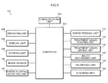
- Fig. 5 is a block diagram illustrating a system configuration of a control system of the inkjet recording apparatus.
- a computer 200 controls operation of each unit. That is, all processing is executed under the control of the computer 200, the processing including paper feeding from the paper feeding unit 110, conveying fed paper sheets P, coating the paper sheets P with treatment liquid in the treatment liquid coating unit 120, drying in the treatment liquid drying unit 130, recording in the inkjet recording unit 140, reading recorded images, drying in the ink drying unit 150, and stacking in the stacking unit 160.
- the computer 200 functions as a control device of the inkjet recording apparatus 100 by executing specified programs.
- the computer 200 is connected to a communicating unit 202, an operating unit 204, a display unit 206, and a storing unit 208.
- the communicating unit 202 which includes a communicating device, performs data exchange with external devices in accordance with a prescribed telecommunications standard under the control of the computer 200.
- the operating unit 204 includes various operating devices for operating the inkjet recording apparatus 100, and inputs information corresponding to operation of the operating devices into the computer 200.
- the display unit 206 includes a display device 170.
- the display device 170 is one example of the display device.
- the display device 170 is configured with a color liquid crystal display.
- the storing unit 208 includes a storing device.
- the storing device is configured with a hard disk drive, for example.
- the storing unit 208 stores a variety of information necessary for control, in addition to the various programs executed by the computer 200.
- Fig. 6 illustrates functional blocks implemented when the computer executes specified programs.
- the computer 200 executes specified programs to function as an image recording control unit 210, a defective nozzle detecting unit 220, a density unevenness detecting unit 222, a non-ejection nozzle information preparing unit 230, a density unevenness correction table preparing unit 232, an image reading control unit 240, a display control unit 250, and a forward/backward movement control unit 260.
- the image recording control unit 210 performs processing of applying various signal processing to image data to generate dot arrangement data, processing of generating driving signals of the inkjet heads based on the generated dot arrangement data, and processing of supplying the generated driving signals to head drivers 212C, 212M, 212Y, and 212K.
- Fig. 7 is a block diagram of the image recording control unit.
- the image recording control unit 210 includes a density data generating unit 210A, a correcting unit 210B, a dot arrangement data generating unit 210C, and a driving signal generating unit 210D.
- the density data generating unit 210A applies density conversion processing to the image data to generate initial density data for each ink color.
- the correcting unit 210B includes a non-ejection correcting unit 210B1 and a density unevenness correcting unit 210B2 to perform non-ejection correction and density unevenness correction of the density data generated by the density data generating unit 210A.
- the non-ejection correcting unit 210B1 performs non-ejection correction of the density data by using non-ejection nozzle information.
- the non-ejection nozzle information is the information on the position of an ejection-disabled nozzle.
- the non-ejection nozzle information is stored in the storing unit 208. As described later, the non-cjcction nozzle information is prepared in the non-ejection nozzle information preparing unit 230.
- the density unevenness correcting unit 210B2 performs density unevenness correction of density data by using a density unevenness correction table.
- the density unevenness correction table is stored in the storing unit 208. As described later, the density unevenness correction table is prepared by the density unevenness correction table preparing unit 232.
- the dot arrangement data generating unit 210C applies half-toning processing to the corrected density data generated by the correcting unit 210B to generate dot arrangement data.
- the driving signal generating unit 210D generates driving signals of the respective inkjet heads 146C, 146M, 146Y, and 146K based on the dot arrangement data generated by the dot arrangement data generating unit 210C.
- the driving signals of the respective inkjet heads 146C, 146M, 146Y, and 146K generated by the driving signal generating unit 210D are added to the head drivers 212C, 212M, 212Y, and 212K of the inkjet heads 146C, 146M, 146Y, and 146K, respectively.
- the head drivers 212C, 212M, 212Y, and 212K drive the inkjet heads 146C, 146M, 146Y, and 146K based on the input driving signals to eject ink from the nozzles.
- the image recording control unit 210 acquires the information thereof and stops recording of an image performed by the ink jet recording unit 145. That is, ejection of the ink from the respective inkjet heads 146C, 146M, 146Y, and 146K is stopped. This means that the image recording control unit 210 also has a function as the image recording stop control unit.
- the defective nozzle detecting unit 220 detects a defective nozzle from the inkjet heads.
- the defective nozzle refers to a non-ejection nozzle and an inclined-ejection nozzle.
- the non-ejection nozzle refers to a nozzle ejection-disabled due to clogging, failure, and the like.
- the inclined-ejection nozzle refers to a nozzle having impact position errors, the amount of which is equal to or more than a specified amount.
- Detection of the defective nozzle is performed based on the result of recording a specified test chart.
- the result of recording is read by the image reader 149.
- the defective nozzle detecting unit 220 analyzes image data of the test chart read by the image reader 149, and detects a defective nozzle.
- Fig. 8 illustrates one example of the test chart for defective nozzle detection.
- the test chart TC illustrated in Fig. 8 is a test chart called a nozzle check pattern.
- the nozzle check pattern is recorded by depositing ink droplets stepwise from the respective nozzles.
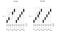
- Figs. 9A and 9B are concept views in the case of detecting a defective nozzle using the nozzle check pattern.
- Fig. 9A is a concept view in the case of detecting a non-ejection nozzle.
- Fig. 9B is a concept view in the case of detecting an inclined-ejection nozzle.
- Fig. 9A illustrates the case where a third nozzle Nz3 from the left is in a non-ejection state.
- the pattern to be formed by the nozzle in the non-ejection state is missing. Therefore, by detecting the position of the missing pattern, the non-ejection nozzle can be detected and the position thereof can be identified.
- Fig. 9B illustrates the case where inclined ejection occurs in a third nozzle Nz3 from the left.
- the recorded pattern of the nozzle having inclined ejection deviates from its regular position.
- the regular position is the position of the pattern recorded when the ejection direction is not inclined. Therefore, by detecting the recorded pattern deviating from the regular position, the inclined-ejection nozzle can be detected and the position thereof can be identified.
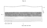
- Fig. 10 illustrates another example of the test chart for defective nozzle detection.
- the test chart TC illustrated in Fig. 10 is a test chart called an isoconcentration patch.
- the isoconcentration patch is a test chart recorded at a uniform density in the entire crosswise region.
- Figs. 11A and 11B are concept views in the case of detecting defective nozzles using the isoconcentration patch.
- Fig. 11A is a concept view in the case of detecting a non-ejection nozzle.
- Fig. 11B is a concept view in the case of detecting an inclined-ejection nozzle.
- Fig. 11A illustrates the case where a third nozzle Nz3 from the left is in the non-ejection state.
- a nozzle is in the non-ejection state when the isoconcentration patch is used, a portion corresponding to the nozzle in the non-ejection state is missing in the recorded chart. Therefore, by detecting the missing portion in the recorded test chart, the non-ejection nozzle can be detected and the position thereof can be identified.
- Fig. 11B illustrates the case where inclined ejection occurs in a third nozzle Nz3 from the left.
- the density in the vicinity of the nozzle causing inclined ejection changes. Therefore, by detecting a density change portion in the recorded test chart, the inclined-ejection nozzle can be detected and the position thereof can be identified.
- Defective nozzle detection is performed for each inkjet head. Since the inkjet recording apparatus 100 of the present embodiment includes four inkjet heads, defective nozzle detection is performed in each of these inkjet heads.
- Defective nozzle detection is constantly carried out during recording. That is, whenever image recording is performed on one paper sheet P, the defective nozzle detection is performed. The defective nozzle detection during recording is carried out by recording the test chart TC for defective nozzle detection in a margin region of the paper sheet P.
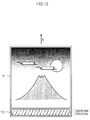
- Fig. 12 illustrates an example of recording an image on the paper sheet.
- a recording target image is recorded on the paper sheet P with a margin.
- the margin is formed in one end of the conveyance direction X of the paper sheet P.
- the test chart TC is recorded on the margin region.
- the inkjet head to be checked may be switched in each sheet, or all the inkjet heads may be checked in each sheet.
- the inkjet head which records the test chart is switched in a regular cycle to record the test chart on the margin region.
- the test chart is recorded on the margin region by all the inkjet heads.
- the density unevenness detecting unit 222 detects the density unevenness of an image recorded by the inkjet heads. Density unevenness detection is performed based on the result of recording a specified test chart. The result of recording is read by the image reader 149. The density unevenness detecting unit 222 analyzes image data of the test chart read by the image reader 149, and detects density unevenness.
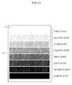
- Fig. 13 illustrates one example of a test chart for detecting density unevenness.
- the test chart TC illustrated in Fig. 13 is a test chart called a density chart.
- the density chart is a chart in which the density is arrayed stepwise.
- an example of the density chart of eight steps is indicated.
- the density from lowest density to highest density is expressed as gradation of eight steps.
- a first step of the chart corresponds to a portion of the lowest density
- an eighth step corresponds to a portion of the highest density.
- the density unevenness detecting unit 222 detects a density value of each gradation level in the density chart, and detects density unevenness in each gradation level.
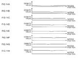
- Figs. 14A to 14H are graph views illustrating examples of gradation density values read from the density chart, respectively.
- a vertical axis represents a density value and a horizontal axis represents a nozzle position in the width direction.
- Figs. 14A to 14H illustrate the results of detecting density values in the first step to the eighth step in the density chart, respectively.
- the density values are detected for the respective gradation levels in the density chart, and density unevenness is detected in each gradation level.
- Density unevenness detection is performed for each inkjet head. Since the inkjet recording apparatus 100 of the present embodiment includes four inkjet heads, detection of density unevenness is performed in each of these inkjet heads. In this case, the test chart of one inkjet head is recorded on one paper sheet, or the test charts of all the inkjet heads may be recorded on one paper sheet.
- Density unevenness detection is carried out in each job.
- the job refers to an image recording command issued to the inkjet recording apparatus.
- density unevenness detection is also carried out at the timing instructed by a user, after startup of the apparatus, after execution of maintenance operation, and the like.
- the non-ejection nozzle information preparing unit 230 prepares non-ejection nozzle information based on the result of defective nozzle detection carried out in the defective nozzle detecting unit 220. That is, the detected defective nozzle is disabled from ejecting, and information on the position of the nozzle is prepared as the non-ejection nozzle information.
- the non-ejection nozzle information is prepared for each inkjet head.
- the prepared non-ejection nozzle information is stored in the storing unit 208.
- the non-ejection correcting unit 210B1 performs non-ejection correction by a known method based on the prepared non-ejection nozzle information. For example, non-ejection correction is performed by increasing the amount of ejection from the nozzles around the ejection-disabled nozzle. The processing of increasing the ejection amount is performed by, for example, increasing the number of dots per unit or increasing a droplet amount.
- the density unevenness correction table preparing unit 232 prepares a density unevenness correction table based on the result of density unevenness detection carried out in the density unevenness detecting unit 222.
- the density unevenness correction table is prepared for each inkjet head.
- the prepared density unevenness correction table is stored in the storing unit 208.
- Fig. 15 is a concept view for preparation of the density unevenness correction table and correction of density unevenness.
- Portion (A) of Fig. 15 illustrates one example of the result of detecting density unevenness.
- Portion (B) of Fig. 15 illustrates one example of the density unevenness correction table prepared from the detection result of the density unevenness illustrated in Portion (A) of Fig. 15 .
- Portion (C) of Fig. 15 is one example of a density value after the density unevenness is corrected using the density unevenness correction table illustrated in Portion (B) of Fig. 15 .
- a vertical axis represents a density value and a horizontal axis represents a nozzle position in a longitudinal direction of the inkjet head.
- the density unevenness correction table preparing unit 232 prepares a density unevenness correction table for all the nozzles to be used so that the density values of the respective gradation levels in the density chart read by the image reader become uniform in the width direction.
- the density unevenness correcting unit 210B2 performs density unevenness correction by performing gradation conversion of density data of an image to be recorded by using the prepared density unevenness correction table. This makes it possible to obtain an image in which the density in the width direction is substantially uniform in each gradation level as illustrated in Portion (C) of Fig. 15 .
- the image reading control unit 240 controls reading by the image reader 149. As described in the foregoing, defective nozzle detection and density unevenness detection are performed by recording a specified test chart on the paper sheet P, and reading the image of the recorded test chart with the image reader 149. When the defective nozzle and density unevenness are detected, the image reading control unit 240 controls driving of the image reader 149 so that the image of the test chart recorded on the paper sheet P is read with the image reader 149.
- driving of the image reader 149 is controlled so that reading is performed in each sheet.
- reading by the image reader 149 is controlled so that the region where the test chart is recorded is read.
- the image reading control unit 240 controls driving of the image reader 149 so that the image of the test chart recorded on the paper sheet P is read with the image reader 149 when the defective nozzle and density unevenness are detected.
- the image reading control unit 240 controls driving of the image reader 149 so that the image of the paper sheet P having floating is read by the image reader 149.
- the image reader 149 reads the image in a fixed front and rear range in the conveyance direction of the paper sheet P with the position where floating is detected as a reference.
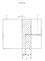
- Fig. 16 is a concept view of reading an image when floating is detected.
- Fig. 16 illustrates the case where a "longitudinal wrinkle" is generated in the paper sheet P, so that floating F is detected.
- the longitudinal wrinkle is a stripe-like wrinkle extending along the conveyance direction X of the paper sheet P.
- a fixed front and rear range along the conveyance direction X of the paper sheet P is set as an image reading range S with the position XP where floating F is detected as a reference.
- a front reading range Sf is set in a fixed front range in the conveyance direction X of the paper sheet P and a rear reading range Sr is set in a fixed rear range, by which the entire reading range S is set.
- a region expressed by a slanting line is the image reading range S.
- the image reading control unit 240 controls driving of the image reader 149 so that the image in the fixed front and rear range in the conveyance direction of the paper sheet P is read with the floating detection position XP as a reference. Specifically, when floating is detected, driving of the image reader 149 is controlled so that reading is started after the lapse of prescribed time from the detection, and reading is finished after the lapse of prescribed time from the start of reading.
- the distance between the position (first position) where the paper floating detecting unit 147 detects floating of the paper sheet P and the position (third position) where the image reader 149 reads an image in the paper sheet P is known, and the conveying speed of the paper sheet P is also known.
- the image in a desired range can be read.
- the time to start reading and the time to finish reading are set in accordance with the reading range S and the conveying speed of the paper sheet P.
- the display control unit 250 controls display of an image on the display device 170.
- Information such as information on an operation condition of the inkjet recording apparatus 100 is displayed on the display device 170.
- the display control unit 250 carries out following display control. That is, when floating of the paper sheet P is detected by the paper floating detecting unit 147, the display control unit 250 acquires an image read with the image reader 149, and displays the image on the display device 170.
- Fig. 17 illustrates an example of a read image displayed on the display device. As illustrated in Fig. 17 , an image G read with the image reader 149 is displayed on the display device 170. An operator can discriminate the type of the floating generated in the paper sheet P by visually confirming the display of the display device 170.
- the forward/backward movement control unit 260 controls a forward/backward moving mechanism 262 provided in the carriage so as to control forward/backward movement of the respective inkjet heads 146C, 146M, 146Y, and 146K. Specifically, the forward/backward movement of the respective inkjet heads 146C, 146M, 146Y, and 146K is controlled so that the preset slow distance is obtained. The forward/backward movement control is performed whenever the thickness of the paper sheet P is changed.
- the forward/backward movement control unit 260 carries out retreating control. More specifically, when floating of the paper sheet P is detected by the paper floating detecting unit 147, the respective inkjet heads 146C, 146M, 146Y, and 146K are simultaneously retreated so that the nozzle faces of the respective inkjet heads 146C, 146M, 146Y, and 146K are moved to the positions at a fixed height from the inkjet recording drum 142, respectively. Accordingly, even when the paper sheet P having floating continues to be conveyed, the paper sheet P can be prevented from contacting the inkjet heads 146C, 146M, 146Y, and 146K.
- the paper sheet P is processed in order of (a) paper feeding, (b) coating with treatment liquid, (c) drying of treatment liquid, (d) image recording, (e) ink drying, and (f) stacking.
- a paper sheet P is fed from the paper feeding unit 110.
- the paper sheet P fed from the paper feeding unit 110 is conveyed to the treatment liquid coating unit 120.
- a recording surface of the paper sheet P is coated with a treatment liquid.
- the paper sheet P coated with the treatment liquid is then conveyed to the treatment liquid drying unit 130. Then, in the process of being conveyed by the treatment liquid drying drum 132 of the treatment liquid drying unit 130, the paper sheet P is dry-processed with warm air blown to the recording surface.
- the dry-processed paper sheet P is then conveyed to the inkjet recording unit 140. Then, in the process of conveying the paper sheet P with the inkjet recording drum 142 of the inkjet recording unit 140, ink droplets of respective colors including cyan, magenta, yellow, and black are deposited to record a color image on the paper sheet P.
- the paper sheet P with the image recorded thereon is then conveyed to the ink drying unit 150. Then, in the process of conveying the paper sheet P by the chain gripper 152 of the ink drying unit 150, heat from the infrared lamps 156A is applied to the recording surface, so that the paper sheet P is dry-processed.
- the dry-processed paper sheet P is then directly conveyed to the stacking unit 160 by the chain gripper 152, and is collected by the stacking device 162 of the stacking unit 160.
- Fig. 18 is a flow chart illustrating processing procedures of the paper sheet in the inkjet recording unit.
- the paper sheet P received and delivered to the inkjet recording drum 142 is first subjected to detection of the presence/absence of floating in the paper floating detecting unit 147 (step S10). Based on the detection result of the floating, the presence/absence of floating is determined (step S11).
- image recording is immediately performed (step S16).
- step S12 image recording on the paper sheet P is stopped (step S12). However, conveyance of the paper sheet P is continuously performed. When recording has already been started, recording is stopped midway. It is to be noted that recording is stopped only for the paper sheet detected to have floating. Even when floating is detected in one paper sheet while recording is performed on a paper sheet preceding thereto, recording on the preceding paper sheet is not stopped. In this case, recording is stopped after image recording on the preceding paper sheet is completed.
- step S13 when image recording is stopped, all the inkjet heads 146C, 146M, 146Y, and 146K are simultaneously retreated from the inkjet recording drum 142 (step S13). As a consequence, it becomes possible to avoid the situation in which the paper sheet P having floating contacts the inkjet heads 146C, 146M, 146Y, and 146K.
- step S14 the image on the paper sheet P detected to have floating is read.
- the image in a fixed front and rear range in the conveyance direction is read with the floating detection position as a reference.
- the read image is then displayed on the display device 170 (step S 15).
- the inkjet recording apparatus 100 of the present embodiment when floating is detected on a paper sheet P by the inkjet recording unit 140, an image of the paper sheet P in a portion where floating is generated is read with the image reader 149, and the image is displayed on the display device 170.
- the operator can discriminate the type of the floating generated in the paper sheet P by visually confirming the display of the display device 170.
- an appropriate measure corresponding to the type of the floating can be taken. That is, since solutions to floating are different depending on the type of the floating, an appropriate measure can be taken when the type of the generated floating can be confirmed.
- the displayed image is not the image of the entire paper sheet but the image of a portion where floating is generated, so that a floating generation position can easily be found out. Furthermore, since the image is read from part of the paper sheet, the processing load in reading operation can be reduced. As a consequence, the processing speed of the paper sheet P can be enhanced.
- the image reader 149 is also used for defective nozzle detection and density unevenness detection, effective use of existing equipment can be achieved.
- the image in a fixed front and rear range is read with the position where the floating is detected as a reference.
- the form of reading is not limited thereto. It is possible to adopt the configuration in which the floating generation portion is read from part of the entire paper sheet.
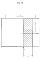
- Fig. 19 is a concept view illustrating another example of image reading when floating is detected.
- a fixed rear range in the conveyance direction X of the paper sheet P may also be set as an image reading range S with the position XP where floating F is detected as a reference.
- an image can be read from part of the entire paper sheet by concentrating attention on the portion where the floating is generated.
- the image reading control unit 240 controls driving of the image reader 149 so that the image in a fixed rear range in the conveyance direction of the paper sheet P is read with the floating detection position XP as a reference. Specifically, when floating is detected, driving of the image reader 149 is controlled so that reading is started after the lapse of prescribed time from the detection, and reading is finished after the lapse of prescribed time from the start of reading.
- the image reading range is set to be the range that is a part in the conveyance direction of the paper sheet P which is at least large enough to enable the type of the floating to be discriminated from the read image.
- the type of the floating can also be discriminated from an image showing part of the floating. Therefore, it is not necessary required to read the entire range of the generated floating. For example, as illustrated in Fig. 17 , floating such as floating caused by a longitudinal wrinkle can be discriminated from the image showing only part thereof.
- Fig. 20 is a concept view illustrating another example of image reading when floating is detected.
- the paper sheet P may be divided into a plurality of regions S1, S2, ... along the conveyance direction X of the paper sheet P, and a region detected to include floating F may be set as an image reading range.
- the floating F is detected in a region S5, so that the region S5 is set as the read region.
- the number of the regions to be divided can properly be set in accordance with the size of the paper sheet P or the like.
- the region where the floating F is detected is set as the image reading range in the aforementioned example
- the floating F detection region and a fixed front and rear region of the floating F detection region may be set as the image reading range.
- the floating F detection region and a fixed rear region of the floating F detection region may be set as the image reading range.
- the image read with the image reader 149 is displayed on the display device 170 without any other reprocessing.
- the processing of emphasizing the floating generated in the paper sheet may be applied to the image, and the processed image may be displayed on the display device 170.
- Fig. 21 is a functional block diagram of the computer in the case of image-processing and displaying a read image.
- the computer 200 executes a specified program to implement the function of the image processing unit 270.
- the image processing unit 270 acquires image data from the image reader 149, and applies the processing of emphasizing the floating generated in a paper sheet to the image data.
- the image processing is the processing of emphasizing contrast.
- the display control unit 250 acquires the image data image-processed in the image processing unit 270, and displays the image data on the display device 170.
- the read image is subjected to the processing of emphasizing floating and is then displayed on the display device 170. Accordingly, when confirming the type of the floating based on the image displayed on the display device 170, the operator can easily confirm the type of the floating.
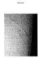
- Fig. 22A is an image of floating actually generated on the inkjet recording drum, the image being taken with a digital camera.
- Fig. 22A illustrates the example in which floating is generated due to a longitudinal wrinkle. Arrows in the image are directly written on the paper sheet with a pen to indicate the position where the floating is generated.
- Fig. 22B is an image of the paper sheet illustrated in Fig. 22A , the image being read with the image reader.
- Fig. 22C is an image obtained by applying processing of emphasizing contrast to the image illustrated in Fig. 22B . As illustrated in Fig. 22C , the processing of emphasizing contrast is applied to emphasize the floating, so that the floating can easily be confirmed from the image.
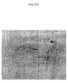
- Fig. 23A is an image of floating actually generated on the inkjet recording drum, the image being taken with the digital camera.
- the example illustrated in Fig. 23A indicates the case where floating is generated due to an annular wrinkle.
- a broken line circle illustrated in the image is directly written on the paper sheet with a pen to indicate the position where the floating is generated.
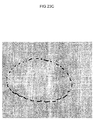
- Fig. 23B is an image of a paper sheet illustrated in Fig. 23A , the image being read with the image reader.
- Fig. 23C is an image obtained by applying processing of emphasizing contrast to the image illustrated in Fig. 23B .
- the processing of emphasizing contrast is applied to emphasize the floating, so that the floating can easily be confirmed from the image.
- the imaging processing for emphasizing the floating is not particularly limited. Processing such as edge emphasis processing other than the processing of emphasizing contrast may also be adopted.
- the configuration in which image processing is executed in response to an instruction from the operator, and an image after the image processing is displayed on the display device 170 may also be adopted.
- an image of the paper sheet read with the image reader is analyzed by a computer, and the type of floating is automatically discriminated. Since the configuration of reading an image on the paper sheet having floating is the same as the configuration of the inkjet recording apparatus described before, only the configuration of automatically discriminating the type of the generated floating is described herein.
- the inkjet recording apparatus of the present embodiment includes a paper sheet floating type discriminating unit 300 which discriminates the type of the floating generated in the paper sheet based on the image read with the image reader.
- the computer 200 executes a specified program to implement a function as the paper sheet floating type discriminating unit 300.
- Fig. 24 is a functional block diagram of the computer which functions as the paper sheet floating type discriminating unit.
- the paper sheet floating type discriminating unit 300 acquires an image read with the image reader 149 and analyzes the acquired image to discriminate the type of the floating generated in the paper sheet P.
- the display control unit 250 acquires information about the result of discrimination by the paper sheet floating type discriminating unit 300, and displays the information on the display device 170.
- the paper sheet floating type discriminating unit 300 analyzes an image read with the image reader 149, and discriminates the type of the floating generated in the paper sheet P. Hereinafter, the discriminating method is described.
- the paper width direction is a direction orthogonal to the conveyance direction X of the paper sheet P.
- the brightness change in the paper width direction is substantially zero.
- the type of floating can be identified by identifying the mode of brightness change.
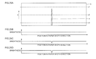
- Figs. 25A to 25D are concept views in the case of detecting a longitudinal wrinkle based on the brightness change.
- Fig. 25A illustrates an image on a paper sheet having a longitudinal wrinkle, the image being read with an image reader.
- Figs. 25B to 25D are graph views illustrating brightness change at positions x1, x2, and x3 of the read image illustrated in Fig. 25A , respectively.
- the brightness change in the paper width direction is substantially zero at the position without floating.
- the longitudinal wrinkle is a linear wrinkle
- the brightness change appears at substantially the same position in the paper width direction.
- Figs. 26A to 26D are concept views in the case of detecting an annular wrinkle based on the brightness change.
- Fig. 26A illustrates an image on a paper sheet having an annular wrinkle, the image being read with the image reader.
- Figs. 26B to 26D are graph views illustrating brightness change at positions x1, x2, and x3 of the read image illustrated in Fig. 26A , respectively.
- Figs. 26B to 26D brightness change appears at two positions in the paper width direction in the case of the annular wrinkle. Also in the case of the annular wrinkle, the generation position changes in the conveyance direction X of the paper sheet P. When such a brightness change is detected from the image, it can be estimated that the type of the floating is an annular wrinkle.
- the annular wrinkle has a characteristic of having a width W larger than that of the longitudinal wrinkle, the width W being the width of a portion having a brightness change. Therefore, when such a characteristic is detected, it can be estimated that the type of floating is an annular wrinkle.
- the type of the floating generated in the paper sheet P can be discriminated based on the brightness change in the image in the paper width direction, the image being read with the image reader 149.
- the paper sheet floating type discriminating unit 300 acquires an image read with the image reader 149 and analyzes the acquired image to discriminate the type of the floating generated in the paper sheet P based on the brightness information.
- the type of the floating generated in the paper sheet can be discriminated by pattern matching with sample images prepared in advance.
- the types of the floating generated in the paper sheet are limited to some extent. Accordingly, two or more kinds of sample images are prepared for each type, and pattern matching with these sample images is performed to determine the type of the floating of the read image. Specifically, correlation coefficients with the respective sample images are calculated, and the type of floating of a sample image with the highest correlation coefficient is regarded as the type of floating of the read image.
- the sample images are stored in the storing unit 208.
- the storing unit 208 is one example of a storing device which functions as a sample image storing unit 208A.
- the paper sheet floating type discriminating unit 300 acquires an image read with the image reader 149 and discriminates the type of floating generated in the paper sheet by pattern matching with the sample images stored in the storing unit 208.
- the sample images are subjected to expansion or reduction processing as necessary, and are then used for the matching processing.
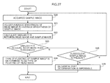
- Fig. 27 is a flow chart illustrating one example of processing procedures in the case of discriminating the type of floating by pattern matching.
- a sample image is acquired (step S20). Sample images are read in a preset order.
- an average brightness of the acquired sample image is adjusted to an average brightness of a read image (step S21).
- precision can be enhanced by using the average brightness of a region without floating. This is because only the whiteness of the paper sheet is theoretically present in the region without floating.
- a similarity R between the read image and the sample image is calculated by a following expression, where I(i, j) represents a brightness value of each pixel of the read image and T(i, j) represents a brightness value of each pixel of the sample image (step S22):
- an upper left corner (or lower left corner) has coordinates of (0, 0)
- a lower right corner (or upper right corner) has coordinates of (m-1, n-1).
- step S23 it is determined whether or not the calculated similarity R is equal to or more than a threshold.
- a threshold For example, a value of 0.3 to 0.5 is set as the threshold.
- the type of the floating into which the sample image is classified is determined as the type of the floating of the read image (step S24), and the processing is ended.
- step S25 When the similarity R is less than the threshold as a result of determination, the presence/absence of a subsequent sample image is determined (step S25). When the subsequent sample image to be compared is present, the sample image is read, and the processing from the steps S20 to S23 is carried out.
- step S26 when the subsequent sample image to be compared is not present, that is, when comparison with all the sample images is finished, it is determined that determination is impossible (step S26), and processing is ended.
- the type of floating generated in the paper sheet can be discriminated.
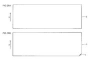
- Figs. 28A and 28B illustrate a read image of a paper sheet without floating and a read image of a paper sheet having floating caused by folding.
- Fig. 28A illustrates the read image of the paper sheet without floating
- Fig. 28B illustrates the read image of the paper sheet having floating caused by folding V.
- the floating due to folding has location dependence and is therefore always generated at the end of the paper sheet.
- the type of floating can easily be discriminated based on the premise that "every paper sheet has a square shape constituted of four straight lines.” That is, when folding is generated in a certain corner, the image of the paper sheet loses its square shape. Accordingly, it becomes possible to discriminate whether folding is generated or not by determining whether or not the read image has a square shape.
- the read image is part of a paper sheet, actually, an edge portion is extracted from the read image, and whether or not the extracted edge portion is constituted of straight lines is determined to detect whether or not folding is generated. Or a corner portion is extracted from the read image, and whether or not the extracted corner portion is at right angles is determined to detect whether or not folding is generated.
- Detection of folding can be used together with the analysis based on brightness or the analysis by pattern matching described before. For example, it is possible to adopt the configuration in which detection of folding is carried out first, and then the analysis based on brightness or analysis by pattern matching is carried out if folding is not detected. In this case, it is also possible to adopt the configuration of carrying out detection of folding only when floating is detected at the end of the paper sheet.
- the result of discrimination by the paper sheet floating type discriminating unit 300 is displayed on the display device 170.
- the display control unit 250 acquires information about the result of discrimination by the paper sheet floating type discriminating unit 300, and displays the information on the display device 170.
- the image read with the image reader 149 may also be displayed.
- the image may be subjected to the processing of emphasizing the floating and then be displayed.
- a conveyance system and/or a paper feeding system are adjusted. Adjustment needs to be performed in accordance with the type of the generated floating.
- the type of floating is discriminated from the image read with the image reader, and a solution corresponding to the type of the generated floating is presented.
- the inkjet recording apparatus includes a solution searching unit 310 which searches for the solution to the floating with reference to a specified database.
- Fig. 29 is a functional block diagram of the computer which functions as the solution searching unit.
- the storing unit 208 connected to the computer 200 stores information on the solution to each type of the floating generated in the paper sheet P as a solution database.
- the storing unit 208 is one example of the storing device which functions as a solution storing unit 208B.
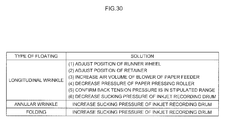
- Fig. 30 is a table illustrating one example of the solution database. As illustrated in Fig. 30 , the solution to each type of floating is registered into the solution database.
- the solution searching unit 310 acquires the information on the type of the generated floating from the paper sheet floating type discriminating unit 300, and searches the solution database for the solution to the floating.
- the information on the solution searched for by the solution searching unit 310 is displayed on the display device 170.
- the display control unit 250 acquires the information on the solution searched for by the solution searching unit 310, and displays the information on the display device 170.
- the information on the type of the floating discriminated by the paper sheet floating type discriminating unit 300 may also be displayed.
- the image read with the image reader 149 may further be displayed. When the image read with the image reader 149 is displayed, the image may be subjected to the processing of emphasizing floating and then be displayed.
- Fig. 31 illustrates an example of a solution to floating displayed on the display device.
- information on the type of generated floating and an image G read with the image reader 149 are displayed together with the information on the solution.
- a setting screen corresponding to the solution is displayed.
- Fig. 31 is one example in which folding is generated.
- the type of floating is discriminated from an image read with the image reader, a solution thereto is searched for, and feed and/or conveyance of the paper sheet is automatically adjusted.
- the method for discriminating the type of floating from the image read with the image reader and searching for the solution thereto is the same as that in the inkjet recording apparatus in each of the embodiments described before. Accordingly, only a method for automatically adjusting the feed and/or conveyance of the paper sheet is described herein.
- the inkjet recording apparatus includes an automatic adjusting unit 320 which automatically adjusts feed and/or conveyance of the paper sheet based on the solution searched for by the solution searching unit 310.
- the computer 200 executes a specified program to implement the function of the automatic adjusting unit 320.
- the automatic adjusting unit 320 is one example of the adjusting device.
- Fig. 32 is a functional block diagram of the computer which functions as the automatic adjusting unit.
- the automatic adjusting unit 320 acquires information on the solution searched for by the solution searching unit 310, and automatically adjusts setting of feed and conveyance. For example, based on the acquired information on the solution, volume of air from the blower is automatically adjusted for the paper feeder 112. Based on the acquired information on the solution, the position of the retainer 114C in the feeder board 114 is also automatically adjusted. Based on the acquired information on the solution, the position of the runner wheel 114A in the feeder board 114 is also automatically adjusted. Based on the acquired information on the solution, the sucking pressure of the inkjet recording drum 142 is also automatically adjusted. Based on the acquired information on the solution, the pressing force of the paper pressing roller 143 is also automatically adjusted. Based on the acquired information on the solution, the sucking pressure of the back tension applying unit 144 is also automatically adjusted.
- the forward/backward movement control unit 260 retreats the inkjet heads 146C, 146M, 146Y, and 146K. However, when floating of the paper sheet P is no longer detected by the paper floating detecting unit 147 after restart of operation, the forward/backward movement control unit 260 returns the inkjet heads 146C, 146M, 146Y, and 146K to the positions before retreat. As a consequence, operation can be resumed safely. This also applies to the case where manual adjustment is performed.
- the paper sheet is conveyed by the drum in the inkjet recording unit.
- the conveying device of the paper sheet is not limited thereto.
- the above configuration may be replaced by the configuration of conveying the paper sheet by sucking the paper sheet to a running belt.
- the configuration of conveying the paper sheet on a platen with a roller may also be adopted.
- floating-up of a certain level or more of the paper sheet is detected with the surface of the belt as a reference, the surface being a suction holding surface.
- floating-up of a certain level or more from the platen is detected as floating.
- the solution database is prepared in conformity with the configuration of the paper feeding system and the conveyance system of the inkjet recording apparatus.
- the automatic adjustment is also performed in conformity with the configuration of the paper feeding system and the conveyance system of the inkjet recording apparatus.
- the paper sheets include sheet-like media at large which are used as recording objects of the inkjet recording apparatus. Therefore, sheets made of resin, such as transparent sheets for overhead projectors, are also embraced in the concept of the paper sheets of the present invention.
Landscapes
- Engineering & Computer Science (AREA)
- Health & Medical Sciences (AREA)
- General Health & Medical Sciences (AREA)
- Biomedical Technology (AREA)
- Multimedia (AREA)
- Signal Processing (AREA)
- Life Sciences & Earth Sciences (AREA)
- Physics & Mathematics (AREA)
- Textile Engineering (AREA)
- Chemical & Material Sciences (AREA)
- Analytical Chemistry (AREA)
- Biochemistry (AREA)
- General Physics & Mathematics (AREA)
- Immunology (AREA)
- Pathology (AREA)
- Ink Jet (AREA)
- Controlling Sheets Or Webs (AREA)
Applications Claiming Priority (1)
| Application Number | Priority Date | Filing Date | Title |
|---|---|---|---|
| JP2015173686A JP6345635B2 (ja) | 2015-09-03 | 2015-09-03 | インクジェット記録装置 |
Publications (2)
| Publication Number | Publication Date |
|---|---|
| EP3141393A1 true EP3141393A1 (de) | 2017-03-15 |
| EP3141393B1 EP3141393B1 (de) | 2018-01-17 |
Family
ID=56852192
Family Applications (1)
| Application Number | Title | Priority Date | Filing Date |
|---|---|---|---|
| EP16186833.6A Active EP3141393B1 (de) | 2015-09-03 | 2016-09-01 | Tintenstrahlaufzeichnungsvorrichtung |
Country Status (3)
| Country | Link |
|---|---|
| US (1) | US9718289B2 (de) |
| EP (1) | EP3141393B1 (de) |
| JP (1) | JP6345635B2 (de) |
Cited By (1)
| Publication number | Priority date | Publication date | Assignee | Title |
|---|---|---|---|---|
| EP4053637A1 (de) * | 2021-03-05 | 2022-09-07 | Ricoh Company, Ltd. | Bildprüfer und bilderzeugungssystem mit dem bildprüfer |
Families Citing this family (6)
| Publication number | Priority date | Publication date | Assignee | Title |
|---|---|---|---|---|
| DE102017210365A1 (de) * | 2016-07-14 | 2018-01-18 | Heidelberger Druckmaschinen Ag | Verfahren zur Steuerung einer Druckmaschine und zum Anhalten von deren Transportvorrichtung |
| JP6769269B2 (ja) * | 2016-12-01 | 2020-10-14 | 富士通株式会社 | 円筒面検査装置および円筒面検査方法 |
| JP6926719B2 (ja) | 2017-06-26 | 2021-08-25 | セイコーエプソン株式会社 | 画像読取装置 |
| DE102017211988A1 (de) * | 2017-07-13 | 2019-01-17 | Heidelberger Druckmaschinen Ag | Detektion ausgefallener Druckdüsen am Druckrand |
| JP6988315B2 (ja) * | 2017-09-25 | 2022-01-05 | 富士フイルムビジネスイノベーション株式会社 | 画像形成装置 |
| JP2021084405A (ja) * | 2019-11-29 | 2021-06-03 | 株式会社リコー | 液体吐出装置及び液体吐出装置における検査用パターン形成方法 |
Citations (10)
| Publication number | Priority date | Publication date | Assignee | Title |
|---|---|---|---|---|
| WO2005108082A1 (de) * | 2004-05-03 | 2005-11-17 | Heidelberger Druckmaschinen Ag | Vorrichtung zur inline-überwachung der druckqualität bei bogenoffsetdruckmaschinen |
| JP2006084595A (ja) | 2004-09-14 | 2006-03-30 | Fuji Xerox Co Ltd | しわ検出装置および画像形成装置 |
| JP2006298606A (ja) | 2005-04-22 | 2006-11-02 | Sharp Corp | 用紙搬送装置の用紙状態検出装置 |
| JP2007301920A (ja) | 2006-05-15 | 2007-11-22 | Mimaki Engineering Co Ltd | 印刷装置、搬送装置、及び印刷方法 |
| JP2010076872A (ja) | 2008-09-25 | 2010-04-08 | Fujifilm Corp | 画像形成装置及び記録媒体の浮き上がり検出方法 |
| JP2012143944A (ja) | 2011-01-11 | 2012-08-02 | Fujifilm Corp | 画像形成装置 |
| EP2657035A1 (de) * | 2012-04-24 | 2013-10-30 | Komori Corporation | Digitale Druckvorrichtung |
| US20130300794A1 (en) * | 2012-05-09 | 2013-11-14 | Xerox Corporation | System and method for detecting defects in an inkjet printer |
| EP2703172A2 (de) * | 2012-08-29 | 2014-03-05 | Seiko Epson Corporation | Flüssigkeitsausstossgerät |
| JP2015037982A (ja) | 2012-08-24 | 2015-02-26 | 株式会社Pfu | 原稿搬送装置、ジャム判定方法及びコンピュータプログラム |
Family Cites Families (8)
| Publication number | Priority date | Publication date | Assignee | Title |
|---|---|---|---|---|
| JP2005153339A (ja) * | 2003-11-26 | 2005-06-16 | Seiko Epson Corp | 不具合問合せ装置、印刷装置、不具合問合せ方法及びそのプログラム |
| WO2006128849A2 (en) * | 2005-05-30 | 2006-12-07 | Agfa Graphics Nv | Collision avoidance method and sensor |
| US8419144B2 (en) * | 2010-05-11 | 2013-04-16 | Xerox Corporation | Media handling device for a printer |
| JP5306498B2 (ja) * | 2011-02-25 | 2013-10-02 | 富士フイルム株式会社 | 画像形成装置 |
| US9027477B2 (en) * | 2013-03-28 | 2015-05-12 | Xerox Corporation | Wrinkle detection in continuous feed printers |
| JP5922058B2 (ja) * | 2013-04-26 | 2016-05-24 | 株式会社東芝 | 分別装置、検知方法 |
| JP2015044345A (ja) * | 2013-08-28 | 2015-03-12 | 富士フイルム株式会社 | インクジェット印刷装置及びニス胴の自動清掃方法 |
| JP6507582B2 (ja) * | 2014-11-13 | 2019-05-08 | セイコーエプソン株式会社 | 印刷装置 |
-
2015
- 2015-09-03 JP JP2015173686A patent/JP6345635B2/ja active Active
-
2016
- 2016-09-01 EP EP16186833.6A patent/EP3141393B1/de active Active
- 2016-09-02 US US15/255,578 patent/US9718289B2/en active Active
Patent Citations (10)
| Publication number | Priority date | Publication date | Assignee | Title |
|---|---|---|---|---|
| WO2005108082A1 (de) * | 2004-05-03 | 2005-11-17 | Heidelberger Druckmaschinen Ag | Vorrichtung zur inline-überwachung der druckqualität bei bogenoffsetdruckmaschinen |
| JP2006084595A (ja) | 2004-09-14 | 2006-03-30 | Fuji Xerox Co Ltd | しわ検出装置および画像形成装置 |
| JP2006298606A (ja) | 2005-04-22 | 2006-11-02 | Sharp Corp | 用紙搬送装置の用紙状態検出装置 |
| JP2007301920A (ja) | 2006-05-15 | 2007-11-22 | Mimaki Engineering Co Ltd | 印刷装置、搬送装置、及び印刷方法 |
| JP2010076872A (ja) | 2008-09-25 | 2010-04-08 | Fujifilm Corp | 画像形成装置及び記録媒体の浮き上がり検出方法 |
| JP2012143944A (ja) | 2011-01-11 | 2012-08-02 | Fujifilm Corp | 画像形成装置 |
| EP2657035A1 (de) * | 2012-04-24 | 2013-10-30 | Komori Corporation | Digitale Druckvorrichtung |
| US20130300794A1 (en) * | 2012-05-09 | 2013-11-14 | Xerox Corporation | System and method for detecting defects in an inkjet printer |
| JP2015037982A (ja) | 2012-08-24 | 2015-02-26 | 株式会社Pfu | 原稿搬送装置、ジャム判定方法及びコンピュータプログラム |
| EP2703172A2 (de) * | 2012-08-29 | 2014-03-05 | Seiko Epson Corporation | Flüssigkeitsausstossgerät |
Cited By (3)
| Publication number | Priority date | Publication date | Assignee | Title |
|---|---|---|---|---|
| EP4053637A1 (de) * | 2021-03-05 | 2022-09-07 | Ricoh Company, Ltd. | Bildprüfer und bilderzeugungssystem mit dem bildprüfer |
| US20220286572A1 (en) * | 2021-03-05 | 2022-09-08 | Ricoh Company, Ltd. | Image inspector and image forming system incorporating the image inspector |
| US11936826B2 (en) * | 2021-03-05 | 2024-03-19 | Ricoh Company, Ltd. | Image inspector for detecting at least one abnormality of a recorded medium and image forming system incorporating the image inspector |
Also Published As
| Publication number | Publication date |
|---|---|
| JP6345635B2 (ja) | 2018-06-20 |
| US9718289B2 (en) | 2017-08-01 |
| JP2017047631A (ja) | 2017-03-09 |
| US20170066262A1 (en) | 2017-03-09 |
| EP3141393B1 (de) | 2018-01-17 |
Similar Documents
| Publication | Publication Date | Title |
|---|---|---|
| EP3141393B1 (de) | Tintenstrahlaufzeichnungsvorrichtung | |
| JP6576316B2 (ja) | 画像検査装置及び方法、プログラム並びにインクジェット印刷システム | |
| JP6694362B2 (ja) | 画像検査方法及び装置、プログラム並びに画像記録システム | |
| JP6571575B2 (ja) | スジ検出方法及び装置、印刷装置並びにプログラム | |
| JP6472058B2 (ja) | 画像形成装置及び画像補正方法 | |
| JP5406086B2 (ja) | 用紙浮き検出装置及びインクジェット記録装置 | |
| US8939528B2 (en) | Inkjet printing apparatus and inkjet printing method | |
| US12182989B2 (en) | Printed matter inspection device, printed matter inspection method, program, and printing apparatus | |
| JP6076848B2 (ja) | インクジェット記録装置 | |
| JP2017094523A (ja) | インクジェット印刷装置及びインクジェットヘッド吐出性能評価方法 | |
| JP2013237251A (ja) | 画像読み取り方法及び画像記録装置 | |
| US8820876B2 (en) | Printing apparatus and inspection method | |
| US20240359495A1 (en) | Printing apparatus and maintenance method thereof | |
| US10752034B2 (en) | Method for detecting ejection abnormality of nozzle and system for detecting ejection abnormality of nozzle | |
| JP6184386B2 (ja) | 画像欠陥検出装置及び方法、画像記録装置並びにプログラム | |
| US12285943B2 (en) | Printing system and defective nozzle detection method | |
| WO2021256389A1 (ja) | 欠陥検査装置、欠陥検査方法及びプログラム、並びに印刷装置、印刷物の製造方法 | |
| US20240278578A1 (en) | Printing apparatus and maintenance method therefor | |
| US11602930B2 (en) | Inkjet recording apparatus | |
| JP2017124890A (ja) | 画像形成システム、及び媒体仕分け方法 | |
| JP2021008034A (ja) | 印刷装置及び印刷方法 | |
| JP2012192545A (ja) | 画像形成装置及び画像形成方法 | |
| US20240399738A1 (en) | System and method for controlling inkjet operation in an inkjet printer using image content data | |
| US12157321B2 (en) | System and method for improving ink image quality in an inkjet printer | |
| JP2022015738A (ja) | 液体吐出装置、検査方法及びプログラム |
Legal Events
| Date | Code | Title | Description |
|---|---|---|---|
| PUAI | Public reference made under article 153(3) epc to a published international application that has entered the european phase |
Free format text: ORIGINAL CODE: 0009012 |
|
| STAA | Information on the status of an ep patent application or granted ep patent |
Free format text: STATUS: THE APPLICATION HAS BEEN PUBLISHED |
|
| STAA | Information on the status of an ep patent application or granted ep patent |
Free format text: STATUS: REQUEST FOR EXAMINATION WAS MADE |
|
| AK | Designated contracting states |
Kind code of ref document: A1 Designated state(s): AL AT BE BG CH CY CZ DE DK EE ES FI FR GB GR HR HU IE IS IT LI LT LU LV MC MK MT NL NO PL PT RO RS SE SI SK SM TR |
|
| AX | Request for extension of the european patent |
Extension state: BA ME |
|
| 17P | Request for examination filed |
Effective date: 20170301 |
|
| RBV | Designated contracting states (corrected) |
Designated state(s): AL AT BE BG CH CY CZ DE DK EE ES FI FR GB GR HR HU IE IS IT LI LT LU LV MC MK MT NL NO PL PT RO RS SE SI SK SM TR |
|
| GRAP | Despatch of communication of intention to grant a patent |
Free format text: ORIGINAL CODE: EPIDOSNIGR1 |
|
| STAA | Information on the status of an ep patent application or granted ep patent |
Free format text: STATUS: GRANT OF PATENT IS INTENDED |
|
| INTG | Intention to grant announced |
Effective date: 20170912 |
|
| GRAS | Grant fee paid |
Free format text: ORIGINAL CODE: EPIDOSNIGR3 |
|
| GRAA | (expected) grant |
Free format text: ORIGINAL CODE: 0009210 |
|
| STAA | Information on the status of an ep patent application or granted ep patent |
Free format text: STATUS: THE PATENT HAS BEEN GRANTED |
|
| AK | Designated contracting states |
Kind code of ref document: B1 Designated state(s): AL AT BE BG CH CY CZ DE DK EE ES FI FR GB GR HR HU IE IS IT LI LT LU LV MC MK MT NL NO PL PT RO RS SE SI SK SM TR |
|
| REG | Reference to a national code |
Ref country code: GB Ref legal event code: FG4D |
|
| REG | Reference to a national code |
Ref country code: CH Ref legal event code: EP |
|
| REG | Reference to a national code |
Ref country code: IE Ref legal event code: FG4D |
|
| REG | Reference to a national code |
Ref country code: DE Ref legal event code: R096 Ref document number: 602016001387 Country of ref document: DE Ref country code: AT Ref legal event code: REF Ref document number: 964141 Country of ref document: AT Kind code of ref document: T Effective date: 20180215 |
|
| REG | Reference to a national code |
Ref country code: NL Ref legal event code: MP Effective date: 20180117 |
|
| REG | Reference to a national code |
Ref country code: LT Ref legal event code: MG4D |
|
| REG | Reference to a national code |
Ref country code: AT Ref legal event code: MK05 Ref document number: 964141 Country of ref document: AT Kind code of ref document: T Effective date: 20180117 |
|
| PG25 | Lapsed in a contracting state [announced via postgrant information from national office to epo] |
Ref country code: NL Free format text: LAPSE BECAUSE OF FAILURE TO SUBMIT A TRANSLATION OF THE DESCRIPTION OR TO PAY THE FEE WITHIN THE PRESCRIBED TIME-LIMIT Effective date: 20180117 |
|
| PG25 | Lapsed in a contracting state [announced via postgrant information from national office to epo] |
Ref country code: FI Free format text: LAPSE BECAUSE OF FAILURE TO SUBMIT A TRANSLATION OF THE DESCRIPTION OR TO PAY THE FEE WITHIN THE PRESCRIBED TIME-LIMIT Effective date: 20180117 Ref country code: NO Free format text: LAPSE BECAUSE OF FAILURE TO SUBMIT A TRANSLATION OF THE DESCRIPTION OR TO PAY THE FEE WITHIN THE PRESCRIBED TIME-LIMIT Effective date: 20180417 Ref country code: LT Free format text: LAPSE BECAUSE OF FAILURE TO SUBMIT A TRANSLATION OF THE DESCRIPTION OR TO PAY THE FEE WITHIN THE PRESCRIBED TIME-LIMIT Effective date: 20180117 Ref country code: HR Free format text: LAPSE BECAUSE OF FAILURE TO SUBMIT A TRANSLATION OF THE DESCRIPTION OR TO PAY THE FEE WITHIN THE PRESCRIBED TIME-LIMIT Effective date: 20180117 Ref country code: ES Free format text: LAPSE BECAUSE OF FAILURE TO SUBMIT A TRANSLATION OF THE DESCRIPTION OR TO PAY THE FEE WITHIN THE PRESCRIBED TIME-LIMIT Effective date: 20180117 Ref country code: CY Free format text: LAPSE BECAUSE OF FAILURE TO SUBMIT A TRANSLATION OF THE DESCRIPTION OR TO PAY THE FEE WITHIN THE PRESCRIBED TIME-LIMIT Effective date: 20180117 |
|
| PG25 | Lapsed in a contracting state [announced via postgrant information from national office to epo] |
Ref country code: GR Free format text: LAPSE BECAUSE OF FAILURE TO SUBMIT A TRANSLATION OF THE DESCRIPTION OR TO PAY THE FEE WITHIN THE PRESCRIBED TIME-LIMIT Effective date: 20180418 Ref country code: BG Free format text: LAPSE BECAUSE OF FAILURE TO SUBMIT A TRANSLATION OF THE DESCRIPTION OR TO PAY THE FEE WITHIN THE PRESCRIBED TIME-LIMIT Effective date: 20180417 Ref country code: IS Free format text: LAPSE BECAUSE OF FAILURE TO SUBMIT A TRANSLATION OF THE DESCRIPTION OR TO PAY THE FEE WITHIN THE PRESCRIBED TIME-LIMIT Effective date: 20180517 Ref country code: PL Free format text: LAPSE BECAUSE OF FAILURE TO SUBMIT A TRANSLATION OF THE DESCRIPTION OR TO PAY THE FEE WITHIN THE PRESCRIBED TIME-LIMIT Effective date: 20180117 Ref country code: LV Free format text: LAPSE BECAUSE OF FAILURE TO SUBMIT A TRANSLATION OF THE DESCRIPTION OR TO PAY THE FEE WITHIN THE PRESCRIBED TIME-LIMIT Effective date: 20180117 Ref country code: SE Free format text: LAPSE BECAUSE OF FAILURE TO SUBMIT A TRANSLATION OF THE DESCRIPTION OR TO PAY THE FEE WITHIN THE PRESCRIBED TIME-LIMIT Effective date: 20180117 Ref country code: RS Free format text: LAPSE BECAUSE OF FAILURE TO SUBMIT A TRANSLATION OF THE DESCRIPTION OR TO PAY THE FEE WITHIN THE PRESCRIBED TIME-LIMIT Effective date: 20180117 Ref country code: AT Free format text: LAPSE BECAUSE OF FAILURE TO SUBMIT A TRANSLATION OF THE DESCRIPTION OR TO PAY THE FEE WITHIN THE PRESCRIBED TIME-LIMIT Effective date: 20180117 |
|
| REG | Reference to a national code |
Ref country code: DE Ref legal event code: R097 Ref document number: 602016001387 Country of ref document: DE |
|
| PG25 | Lapsed in a contracting state [announced via postgrant information from national office to epo] |
Ref country code: EE Free format text: LAPSE BECAUSE OF FAILURE TO SUBMIT A TRANSLATION OF THE DESCRIPTION OR TO PAY THE FEE WITHIN THE PRESCRIBED TIME-LIMIT Effective date: 20180117 Ref country code: AL Free format text: LAPSE BECAUSE OF FAILURE TO SUBMIT A TRANSLATION OF THE DESCRIPTION OR TO PAY THE FEE WITHIN THE PRESCRIBED TIME-LIMIT Effective date: 20180117 Ref country code: IT Free format text: LAPSE BECAUSE OF FAILURE TO SUBMIT A TRANSLATION OF THE DESCRIPTION OR TO PAY THE FEE WITHIN THE PRESCRIBED TIME-LIMIT Effective date: 20180117 Ref country code: RO Free format text: LAPSE BECAUSE OF FAILURE TO SUBMIT A TRANSLATION OF THE DESCRIPTION OR TO PAY THE FEE WITHIN THE PRESCRIBED TIME-LIMIT Effective date: 20180117 |
|
| PLBE | No opposition filed within time limit |
Free format text: ORIGINAL CODE: 0009261 |
|
| STAA | Information on the status of an ep patent application or granted ep patent |
Free format text: STATUS: NO OPPOSITION FILED WITHIN TIME LIMIT |
|
| PG25 | Lapsed in a contracting state [announced via postgrant information from national office to epo] |
Ref country code: CZ Free format text: LAPSE BECAUSE OF FAILURE TO SUBMIT A TRANSLATION OF THE DESCRIPTION OR TO PAY THE FEE WITHIN THE PRESCRIBED TIME-LIMIT Effective date: 20180117 Ref country code: SM Free format text: LAPSE BECAUSE OF FAILURE TO SUBMIT A TRANSLATION OF THE DESCRIPTION OR TO PAY THE FEE WITHIN THE PRESCRIBED TIME-LIMIT Effective date: 20180117 Ref country code: SK Free format text: LAPSE BECAUSE OF FAILURE TO SUBMIT A TRANSLATION OF THE DESCRIPTION OR TO PAY THE FEE WITHIN THE PRESCRIBED TIME-LIMIT Effective date: 20180117 Ref country code: DK Free format text: LAPSE BECAUSE OF FAILURE TO SUBMIT A TRANSLATION OF THE DESCRIPTION OR TO PAY THE FEE WITHIN THE PRESCRIBED TIME-LIMIT Effective date: 20180117 |
|
| 26N | No opposition filed |
Effective date: 20181018 |
|
| PG25 | Lapsed in a contracting state [announced via postgrant information from national office to epo] |
Ref country code: SI Free format text: LAPSE BECAUSE OF FAILURE TO SUBMIT A TRANSLATION OF THE DESCRIPTION OR TO PAY THE FEE WITHIN THE PRESCRIBED TIME-LIMIT Effective date: 20180117 |
|
| PG25 | Lapsed in a contracting state [announced via postgrant information from national office to epo] |
Ref country code: MC Free format text: LAPSE BECAUSE OF FAILURE TO SUBMIT A TRANSLATION OF THE DESCRIPTION OR TO PAY THE FEE WITHIN THE PRESCRIBED TIME-LIMIT Effective date: 20180117 |
|
| REG | Reference to a national code |
Ref country code: BE Ref legal event code: MM Effective date: 20180930 |
|
| REG | Reference to a national code |
Ref country code: IE Ref legal event code: MM4A |
|
| PG25 | Lapsed in a contracting state [announced via postgrant information from national office to epo] |
Ref country code: LU Free format text: LAPSE BECAUSE OF NON-PAYMENT OF DUE FEES Effective date: 20180901 |
|
| PG25 | Lapsed in a contracting state [announced via postgrant information from national office to epo] |
Ref country code: IE Free format text: LAPSE BECAUSE OF NON-PAYMENT OF DUE FEES Effective date: 20180901 |
|
| PG25 | Lapsed in a contracting state [announced via postgrant information from national office to epo] |
Ref country code: FR Free format text: LAPSE BECAUSE OF NON-PAYMENT OF DUE FEES Effective date: 20180930 Ref country code: BE Free format text: LAPSE BECAUSE OF NON-PAYMENT OF DUE FEES Effective date: 20180930 |
|
| PG25 | Lapsed in a contracting state [announced via postgrant information from national office to epo] |
Ref country code: MT Free format text: LAPSE BECAUSE OF NON-PAYMENT OF DUE FEES Effective date: 20180901 |
|
| PG25 | Lapsed in a contracting state [announced via postgrant information from national office to epo] |
Ref country code: TR Free format text: LAPSE BECAUSE OF FAILURE TO SUBMIT A TRANSLATION OF THE DESCRIPTION OR TO PAY THE FEE WITHIN THE PRESCRIBED TIME-LIMIT Effective date: 20180117 |
|
| PG25 | Lapsed in a contracting state [announced via postgrant information from national office to epo] |
Ref country code: PT Free format text: LAPSE BECAUSE OF FAILURE TO SUBMIT A TRANSLATION OF THE DESCRIPTION OR TO PAY THE FEE WITHIN THE PRESCRIBED TIME-LIMIT Effective date: 20180117 |
|
| REG | Reference to a national code |
Ref country code: CH Ref legal event code: PL |
|
| PG25 | Lapsed in a contracting state [announced via postgrant information from national office to epo] |
Ref country code: MK Free format text: LAPSE BECAUSE OF NON-PAYMENT OF DUE FEES Effective date: 20180117 Ref country code: HU Free format text: LAPSE BECAUSE OF FAILURE TO SUBMIT A TRANSLATION OF THE DESCRIPTION OR TO PAY THE FEE WITHIN THE PRESCRIBED TIME-LIMIT; INVALID AB INITIO Effective date: 20160901 |
|
| PG25 | Lapsed in a contracting state [announced via postgrant information from national office to epo] |
Ref country code: LI Free format text: LAPSE BECAUSE OF NON-PAYMENT OF DUE FEES Effective date: 20190930 Ref country code: CH Free format text: LAPSE BECAUSE OF NON-PAYMENT OF DUE FEES Effective date: 20190930 |
|
| GBPC | Gb: european patent ceased through non-payment of renewal fee |
Effective date: 20200901 |
|
| PG25 | Lapsed in a contracting state [announced via postgrant information from national office to epo] |
Ref country code: GB Free format text: LAPSE BECAUSE OF NON-PAYMENT OF DUE FEES Effective date: 20200901 |
|
| P01 | Opt-out of the competence of the unified patent court (upc) registered |
Effective date: 20230515 |
|
| PGFP | Annual fee paid to national office [announced via postgrant information from national office to epo] |
Ref country code: DE Payment date: 20250730 Year of fee payment: 10 |