EP3141406B1 - Attelage - Google Patents
Attelage Download PDFInfo
- Publication number
- EP3141406B1 EP3141406B1 EP16187841.8A EP16187841A EP3141406B1 EP 3141406 B1 EP3141406 B1 EP 3141406B1 EP 16187841 A EP16187841 A EP 16187841A EP 3141406 B1 EP3141406 B1 EP 3141406B1
- Authority
- EP
- European Patent Office
- Prior art keywords
- latching
- pivot bearing
- guide
- pivot
- actuating
- Prior art date
- Legal status (The legal status is an assumption and is not a legal conclusion. Google has not performed a legal analysis and makes no representation as to the accuracy of the status listed.)
- Active
Links
Images








Classifications
-
- B—PERFORMING OPERATIONS; TRANSPORTING
- B60—VEHICLES IN GENERAL
- B60D—VEHICLE CONNECTIONS
- B60D1/00—Traction couplings; Hitches; Draw-gear; Towing devices
- B60D1/01—Traction couplings or hitches characterised by their type
- B60D1/06—Ball-and-socket hitches
- B60D1/065—Ball-and-socket hitches characterised by the hitch mechanism
-
- B—PERFORMING OPERATIONS; TRANSPORTING
- B60—VEHICLES IN GENERAL
- B60D—VEHICLE CONNECTIONS
- B60D1/00—Traction couplings; Hitches; Draw-gear; Towing devices
- B60D1/01—Traction couplings or hitches characterised by their type
- B60D1/06—Ball-and-socket hitches
-
- B—PERFORMING OPERATIONS; TRANSPORTING
- B60—VEHICLES IN GENERAL
- B60D—VEHICLE CONNECTIONS
- B60D1/00—Traction couplings; Hitches; Draw-gear; Towing devices
- B60D1/24—Traction couplings; Hitches; Draw-gear; Towing devices characterised by arrangements for particular functions
- B60D1/246—Traction couplings; Hitches; Draw-gear; Towing devices characterised by arrangements for particular functions for actuating the hitch by powered means
-
- B—PERFORMING OPERATIONS; TRANSPORTING
- B60—VEHICLES IN GENERAL
- B60D—VEHICLE CONNECTIONS
- B60D1/00—Traction couplings; Hitches; Draw-gear; Towing devices
- B60D1/24—Traction couplings; Hitches; Draw-gear; Towing devices characterised by arrangements for particular functions
- B60D1/42—Traction couplings; Hitches; Draw-gear; Towing devices characterised by arrangements for particular functions for being adjustable
- B60D1/44—Traction couplings; Hitches; Draw-gear; Towing devices characterised by arrangements for particular functions for being adjustable horizontally
-
- B—PERFORMING OPERATIONS; TRANSPORTING
- B60—VEHICLES IN GENERAL
- B60D—VEHICLE CONNECTIONS
- B60D1/00—Traction couplings; Hitches; Draw-gear; Towing devices
- B60D1/24—Traction couplings; Hitches; Draw-gear; Towing devices characterised by arrangements for particular functions
- B60D1/42—Traction couplings; Hitches; Draw-gear; Towing devices characterised by arrangements for particular functions for being adjustable
- B60D1/46—Traction couplings; Hitches; Draw-gear; Towing devices characterised by arrangements for particular functions for being adjustable vertically
-
- B—PERFORMING OPERATIONS; TRANSPORTING
- B60—VEHICLES IN GENERAL
- B60D—VEHICLE CONNECTIONS
- B60D1/00—Traction couplings; Hitches; Draw-gear; Towing devices
- B60D1/48—Traction couplings; Hitches; Draw-gear; Towing devices characterised by the mounting
- B60D1/54—Traction couplings; Hitches; Draw-gear; Towing devices characterised by the mounting collapsible or retractable when not in use, e.g. hide-away hitches
-
- B—PERFORMING OPERATIONS; TRANSPORTING
- B60—VEHICLES IN GENERAL
- B60D—VEHICLE CONNECTIONS
- B60D1/00—Traction couplings; Hitches; Draw-gear; Towing devices
- B60D1/58—Auxiliary devices
- B60D1/62—Auxiliary devices involving supply lines, electric circuits or the like
Definitions
- the invention relates to a trailer coupling comprising a ball neck movable between a working position and a rest position with a swivel bearing body arranged at a first end and a coupling ball arranged at a second end, a swivel bearing unit arranged fixed to the vehicle, by means of which the swivel bearing body rotates about the swivel axis between the working position and the rest position is pivotally received, and a rotary blocking device with at least two rotary blocking bodies, which are guided by means of a guide body in a guide direction with at least one component so as to be movable in the radial direction to the pivot axis, the rotary blocking bodies in the working position being able to be brought into a rotary blocking position by movement in the guide direction and in this is in engagement with a receptacle in the pivot bearing body in order to block a pivoting movement of the pivot bearing body about the pivot axis relative to the guide body ockieren, and can be brought into a release position
- Such towbars are for example from the EP 1 741 572 A1 known.
- the EP 2 266 820 A1 discloses a trailer hitch according to the preamble of claim 1.
- a rest position locking device which is independent of the rotation blocking device is provided, which in a release position permits movement of the swivel bearing body relative to the guide body and, in a rest position rest position, fixes the swivel bearing body relative to the guide body in a rotationally fixed manner and at least in the rotational position of the swivel bearing body corresponding to the rest position automatically changes into the latching position.
- the rest locking device in such a way that it triggers automatically, for example electrically, when the rest position is reached.
- the rest position latch device automatically changes to the latch position when the pivot position of the pivot bearing body corresponding to the rest position is reached due to a spring element provided in this rest position latch device, so that no actuation of a latch element required by a control is required, but instead there is a mechanically automatic function of the rest locking device, which ensures high reliability.
- the rest position locking device In order to be able to move the rest position locking device in a suitable manner from the rest position rest position into the release position, it is preferably provided that the rest position rest device can be released depending on a specific functional state of the trailer coupling.
- the functional state of the trailer coupling is a control command for swiveling the ball neck from the rest position into the working position or even a beginning swiveling of the ball neck from the rest position into the working position.
- the rest position rest device can be released from the rest position into the working position at the beginning of a pivoting of the pivot bearing body.
- such a drive unit could act directly on a latching body of the rest position latching device in order to move it from the rest position latching position into the release position.
- a particularly advantageous solution provides that a drive unit provided for pivoting the ball neck transfers the rest position device into the release position via a pivot drive for the ball neck.
- the advantage of this solution is that the swivel drive can be used to ensure in a simple manner that the rest position locking device is only transferred from the rest position to the release position at the beginning of the swiveling of the swivel bearing body and thus of the ball neck.
- a particularly simple solution provides that the swivel drive transfers the rest position locking device into the release position before the swivel bearing body is swiveled.
- the rest position locking device comprises a locking body which is arranged in one of the bodies and movable in a locking direction and which can be brought into engagement with a locking receptacle arranged in another of the bodies.
- the formation of the rest position latching device is particularly simple when the latching body movable in the latching direction is arranged in the guide body and the latching receptacle is arranged in the swivel bearing body.
- the latching receptacle is assigned a latching release body which, when actuated, displaces the latching body from the latching receptacle and thus transfers it to the release position .
- the latch release body can be actuated by a pivot drive for the pivot bearing body.
- the rest position device is transferred from the rest position to the release position by the pivot drive during the release.
- a release position latching device which, in a release position of the actuating body, between a latching release position releasing movement of the actuating body relative to the guide body and a latching position which defines the actuating body relative to the guide body Locking position is movable and is acted upon by a spring element in the direction of the locking position at least in the release position of the actuating body.
- the release position locking device automatically changes into the locking position in the release position of the actuating body when the pivot bearing body has left the rotational position corresponding to the working position.
- the release position locking device changes from the locking position to the locking release position when at least one functional position of the trailer coupling is reached and thus in turn releases the movement of the actuating body, in particular in the direction of its rotational blocking position.
- the functional position does not correspond to the rest position of the trailer coupling, but is a position encompassing the working position.
- the functional position is that of the working position of the trailer coupling, so that it is ensured that the release position locking device can always pass from the locking position into the locking release position in the working position and thus the rotation blocking device can be active in the working position.
- the transition from the locking position to the locking release position could take place by detecting a wide variety of variables influencing the function of the trailer coupling.
- the position of the ball neck in particular the working position of the ball neck, could be recorded electronically and then the transition of the release position locking device from the locking position into the locking release position could be initiated electronically.
- the individual functional positions of the trailer coupling can be detected particularly simply by detecting a rotational position of the swivel bearing body, so that the release position locking device changes from the detent position to the detent release position as a function of at least one specific rotational position of the pivot bearing body.
- the release position locking device changes from the locking position to the locking release position when at least one predetermined rotational position of the swivel bearing body is reached, that is to say that it can thereby be determined in a simple manner from which rotational position of the pivot bearing body the release position locking device changes from the locking position to the locking release position should pass.
- the release position locking device passes mechanically controlled from the locking position into the locking release position when the at least one predetermined rotational position of the swivel bearing body is reached.
- the mechanical control of the transition from the locking position to the locking release position ensures a particularly high level of functional reliability, since an essential safety aspect is that the rotary blocking device always changes automatically into the rotary blocking position in the working position and remains in it.
- the release position locking device comprises a locking body guided in one of the bodies in a locking direction and a locking receptacle provided in the other of the body, in which the locking body engages in the locking position and is disengaged in the locking release position.
- latching body is arranged in the actuating body in the latching direction and the latching receptacle is arranged in the guide body.
- a sensing element is arranged in the snap-in receptacle, which detects the presence of rotational positions of the swivel bearing body relative to the guide body and thus can mechanically recognize the rotational positions of the swivel bearing body relative to the guide body .
- this can advantageously be achieved in that the probe body scans a contour arranged on the swivel bearing body and movable with the swivel bearing body to detect the individual rotational positions of the swivel bearing body.
- the feeler body displaces the latching body from the latching receptacle in at least one predetermined rotational position of the pivot bearing body and thus moves it from the latching position into the Lock release position moves.
- the locking body and the locking receptacle could be aligned such that the locking direction runs radially to the pivot axis.
- a solution which is particularly advantageous in terms of construction provides, however, that the latching body can be moved in a latching direction running parallel to the pivot axis.
- the rotation blocking device comprises at least three rotation blocking bodies.
- a particularly favorable solution provides that the rotary blocking bodies are arranged relative to the actuating body in such a way that at least their reaction forces acting transversely to the pivot axis and acting on the actuating body are at least partially compensated.
- the actuating body does not have to be designed so that it has to be stably supported to absorb the reaction forces acting on it from the rotary blocking bodies, but can be stored very easily if the rotating blocking bodies move on the At least partially cancel the actuating body acting reaction forces.
- the rotary blocking bodies are arranged relative to the actuating body in such a way that at least their reaction forces directed transversely to the pivot axis and acting on the actuating body essentially cancel each other out.
- rotary blocking bodies are arranged relative to the actuating body in such a way that their reaction forces acting on the actuating body are at least partially canceled out.
- the rotary blocking bodies can be arranged in any manner relative to the actuating body.
- An exemplary embodiment provides that the rotational blocking bodies are arranged around the actuating body.
- rotation blocking bodies are arranged essentially symmetrically to a plane running perpendicular to the pivot axis.
- At least two of the rotation blocking bodies cooperate with the receptacles provided for them in such a way that they generate opposing torques on the swivel bearing body.
- the actuating body has wedge surfaces which extend over an angular range around the pivot axis and vary in their radial distance from the pivot axis and with which the rotary blocking bodies can be acted upon.
- the rotation blocking body is guided by a guide body adjoining the pivot bearing body in the radial direction.
- the guide body is preferably designed such that it has a guide sleeve with the guide receptacle for the respective rotational blocking body.
- a guide body provided in this way can advantageously also be used, in particular, for a bearing for the actuating body to be connected to the guide body, so that the actuating body can thereby be mounted in a simple and inexpensive manner.
- a favorable solution provides that the guide body forms a swivel bearing for the swivel bearing body, so that the guide body offers the advantage, in addition to the guide function, of taking over the bearing function for the swivel body.
- the guide body is expediently arranged in such a way that it is part of the swivel bearing unit arranged fixed to the vehicle.
- the swivel bearing body forms an outer body that surrounds the swivel bearing unit on the outside and is arranged immovably in relation to the swivel bearing unit and the guide body in the direction of the swivel axis.
- Such an arrangement of the pivot bearing body has on the one hand the advantage of a favorable spatial structure of the pivot bearing unit itself and the advantage of a relatively simple sealing of the pivot bearing unit, since the pivot bearing body does not make any movements in the axial direction of the pivot axis.
- Seals are provided between a housing of the swivel bearing unit and both end sides of the outer body around the swivel axis, with which seals are made against ingress of dirt and moisture.
- a particularly favorable exemplary embodiment provides that the first end of the ball neck is attached to the outer body.
- the swivel bearing body forms an outer body which surrounds the rotation blocking device and is arranged so as to be immovable relative to the guide body in the direction of the swivel axis.
- the rotary blocking bodies can be moved by the actuating body from a release position into a rotary blocking position.
- the actuating body is preferably designed such that it allows the rotational blocking body to be released in the release position.
- actuating body provides that in the rotational blocking position it holds the rotational blocking body in its rotational blocking position.
- the actuating body is acted upon in the direction of its rotational blocking position by an elastic force accumulator, in particular by a torsion spring.
- Such an elastic energy store could in principle be arranged at several locations.
- the elastic energy accumulator is arranged within the guide body.
- Another structurally advantageous solution provides that the elastic energy accumulator is arranged on one side of the actuating body.
- the elastic energy accumulator can advantageously be coupled to the actuating body.
- an actuating device is preferably provided, by means of which the actuating body can be moved from the rotational blocking position into the release position.
- the actuating device is designed such that it can be used to move the actuating body against the action of the energy accumulator.
- actuating body In the case of a rotatably provided actuating body, it is provided that the actuating body can be rotated in the opposite direction to the direction of rotation caused by the energy accumulator.
- the actuating device has a drive element which is coupled to the actuating body.
- Such a coupling between the drive element and the actuating body can be designed in a wide variety of ways.
- a solution would be a direct connection between the drive element and the actuating body.
- the drive element and the actuating body are coupled to one another via a driving coupling device.
- Such a driving coupling device can be designed in a wide variety of ways.
- An advantageous embodiment provides that the driving coupling device has a driving-free release state and a driving state.
- An embodiment of a trailer coupling according to the invention provides that the driving coupling device is designed such that moving the drive element starting from an initial position only results in a movement of the actuating body after passing through a free state and reaching the driving state in an intermediate position.
- a motorized drive provides as a swivel drive for executing the swivel movement of the swivel bearing body.
- a motor drive being provided for actuating the rotary blocking device and a motor drive being provided for carrying out the pivoting movement of the pivot bearing body.
- a corresponding sensor system must be used to determine when the rotary blocking device is in the rotational blocking position or the freewheeling position and when the pivot bearing body is in the position corresponding to the working position or the position corresponding to the rest position, and the drive power in accordance with the positions detected by the sensor system switch from one drive to the other.
- an advantageous solution therefore provides that the drive for the rotary blocking device and the drive for the pivoting movement of the pivot bearing body are coupled by a planetary gear.
- Such a planetary gear allows the two movements to be coupled with one another.
- Such a planetary gear is particularly suitable, in which the planetary gear can be driven by a single motor drive.
- the planetary gear is preferably integrated between an output for actuating the rotary blocking device and an output for executing the pivoting movement of the pivot bearing body in such a way that the planetary gear allows a change between a drive of the rotary blocking device and the pivoting movement of the pivot bearing body.
- a drive of the various functions of the trailer coupling according to the invention is particularly advantageously possible if a planetary gear is provided, which is driven by a motor drive unit, and if an output of the planetary gear acts as an actuator on the actuating body to move it from the rotational blocking position into the release position and / or if necessary to move the other way round, and if another output of the planetary gear acts as a pivot drive on the pivot bearing body for pivoting the ball neck between the working position and the rest position.
- a planetary gear allows a change from one output to the other output in a simple manner and thus one drive unit, for example comprising an electric drive motor and possibly a gear, is sufficient to alternate via the one output to drive the movements of the actuating body and to drive the pivoting movement of the ball neck between the working position and the rest position via the other output.
- one drive unit for example comprising an electric drive motor and possibly a gear
- a sun gear of the planetary gear can be driven by the motor drive.
- a ring gear of the planetary gear is coupled to the output for the rotation blocking device.
- a planet gear carrier of the planetary gear is coupled to the output for the pivoting movement.
- Such an inhibition of the pivoting movement or the rotary blocking device can be implemented in different ways.
- the swivel movement can be inhibited in a simple manner by the swivel bearing part being lockable relative to the guide body, so that the swivel movement is inevitably inhibited when the swivel bearing part is locked.
- the drive of the rotary blocking device can be inhibited in a wide variety of ways.
- a particularly favorable solution provides that the release position locking device is provided to inhibit the drive of the rotary blocking device.
- the planetary gear is arranged on a side of the actuating body facing the motor drive, so that the planetary gear can be used in a simple manner to drive the actuating body.
- the planetary gear is driven on one side by the motor drive and has an output for the actuating body on the opposite side.
- a structurally particularly expedient solution provides that the planetary gear is arranged between the motor drive and the actuating body, viewed in the direction of the pivot axis.
- a further advantageous solution therefore provides that the actuating body can be blocked by a securing device.
- a solution in which the actuating body can be blocked by the securing device against reaching its inactive position is particularly advantageous, in order to ensure that the actuating body never independently, for example in the event of a breakage of the elastic force accumulator acting on it in the direction of its active position, the release position of the rotational blocking bodies allows.
- Such a safety device is designed such that it requires an action to remove the blocking of the actuating body.
- the actuating device is coupled to the securing device, so that the actuating device can also be used to release the blocking of the actuating body by the securing device.
- the securing device is preferably coupled to the actuating device in such a way that the securing device blocks a movement of the actuating body that is not triggered by an actuation.
- the securing device is designed such that it blocks a movement of the actuating body into its release position when the actuating device is not actuated.
- An expedient solution provides for the drive element of the actuating device, for example the output element of the planetary gear, to be coupled to the securing device.
- the drive element for example the output element of the planetary gear
- the drive element can expediently be designed such that the action on the actuating body and the action on the securing device are coordinated with one another via the drive element, so that actuation of the actuating device on the one hand leads to the blocking of the actuating body is lifted and on the other hand leads to the actuating body being moved from the active position to the inactive position.
- the drive element transfers the securing device from the securing position into the unlocking position in the course of its movement from the starting position into an intermediate position.
- any type of coupling for example via an electrical control, would also be conceivable.
- a solution which is particularly expedient due to its simplicity provides that the drive element and the securing device are coupled to one another via a mechanical coupling device.
- the mechanical coupling device is advantageously designed such that it controls the action on the securing device by means of a slide track.
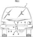
- a first embodiment of a trailer coupling AK according to the invention for a motor vehicle shown in Fig. 1 , 2nd and 3rd in a working position A and in Fig. 4 and 5 in a rest position R, comprises a ball neck designated as a whole with 10, which is held with a first end 12 on a pivot bearing body 14 and carries a coupling ball designated as a whole with 18 at a second end 16, to which a coupling ball receptacle of a trailer can be fixed.
- the pivot bearing body 14 is pivotally mounted about a pivot axis 22 relative to a carrier 24 fixed to the vehicle by means of a pivot bearing unit designated as a whole, the carrier 24 preferably having a support plate 26 holding the pivot bearing unit 20, which preferably extends in a plane perpendicular to the pivot axis 22 , and has a vehicle-fixed cross member 28, which can be fastened in a known manner to a rear region H of a vehicle body F, in such a way that the pivot bearing unit 20 and the carrier 24 lie on a side of a lower edge 30 of a bumper unit 36 facing away from a road surface, and through the bumper unit 36 are covered ( Fig. 2 ).
- the ball neck 10 engages with a section 32 adjoining the first end 12, the lower edge 30 of the bumper unit 36, so that the second end 16 and the coupling ball 18 together with a socket receptacle 34 are on a side of the rear bumper unit 36 facing away from the vehicle body, while in the rest position both the pivot bearing unit 20 and the entire ball neck 10 together with the coupling ball 18 are covered by the rear bumper unit 36 from behind.
- the pivot bearing unit 20 comprises, as in FIG 6 to 9 shown, a guide body 40 which is fixedly connected to the support plate 26 with a flange 42 and a guide sleeve 44 extending from the flange 42 away from the support plate 26 and on which the pivot bearing body 14 is rotatably mounted.
- the guide sleeve 44 comprises a cylindrical outer circumferential surface 46, on which the swivel bearing body 14 rests with a cylindrical inner surface 48 and is thereby rotated about the swivel axis 22 about the axis 22, so that the swivel bearing body 14 can be rotated relative to the guide body 40 such that the Ball neck 10 is pivotable from the working position A to the rest position R and vice versa.
- the guide body 40 thus forms, through its fixed connection with the carrier plate 26 and the carrier 24, the vehicle-mounted rotary bearing for the pivot bearing body 14.
- the swivel bearing unit 20 is provided with a rotary blocking device, designated as a whole by 50, which has an actuating body 52, a plurality of rotating blocking bodies 54 which can be acted upon by the actuating body 52 and which are arranged in guide receptacles 56 of the guide sleeve 44 in an essentially radial manner Swivel axis 22 extending guide direction 58 are movably guided, and, starting from the inner surface 48 of the swivel bearing body 14, includes receptacles 60 extending into the latter, with which the rotational blocking bodies can be brought into engagement in the working position A, the receptacles 60 increasing in the radial direction to the swivel axis 22 have a smaller distance from each other wall surfaces.
- a set of three rotary blocking bodies 54a, 54b and 54c the guide sleeve 44 has a corresponding set of three guide receptacles 56a, 56b and 56c, in which the rotary blocking bodies 54a, 54b and 54c in the substantially radial to the pivot axis 22 extending guide direction 58 are slidably guided, and the pivot bearing body 14 is provided with a set of first receptacles 60a, 60b and 60c, with which the rotation blocking bodies 54a, 54b and 54c can be brought into engagement in the working position A.
- the actuating body 52 is provided with a set of a total of three retraction receptacles 62a, 62b and 62c and three corresponding to the number of the rotary blocking bodies 54 and three in a circumferential direction 64
- the pressure surfaces 66 preferably run as spiral or involute segments relative to the pivot axis 22.
- the actuating body 52 is also about the pivot axis 22, in particular coaxially the latter, rotatable in such a way that either the set of retraction receptacles 62a, 62b and 62c faces the rotation blocking bodies 54 and these, as in FIG Fig.
- a rotation of the actuating body 52 in the case of rotary blocking bodies 54 seated in the retraction receptacles 62 in a direction of rotation 72 opposite to the direction of rotation 64 has the effect that the rotational blocking bodies 54 are moved out of the retraction receptacles 62 and initially, as in FIG Fig. 7 shown, in the active position of the actuating body 52 seated on the initial areas 68 of the pressure surfaces 66, but in the process, for example, immersed in the first receptacles 56 and thus preventing the free rotation of the pivot bearing body 14 relative to the guide body 40.
- the actuating body 52 In the rotational blocking position of the rotational blocking body 54, the actuating body 52 is in its active position such that the rotational blocking body 54, as in FIG Fig. 7 shown, approximately on central regions 76, which lie between the start regions 68 and the end regions 70, of the pressure surfaces 66 and are acted upon by them.
- the play-free locking of the pivot bearing body 14 by the rotary blocking body 54 can be achieved particularly favorably if the rotating blocking body 54 and the receptacles 60 are designed such that when one of the rotating blocking bodies 54 is increasingly immersed in one of the receptacles 60 and the rotating blocking bodies 54 are in contact with one Side of the receptacles 60 cause a rotation of the pivot bearing body 14 and the set of rotary blocking bodies 54a to 54c acts on the receptacles 60 for play-free fixing of the pivot bearing body 14 with torques 90, 92 acting in opposite directions ( Fig. 7 ).
- the actuating body 52 In order to give the actuating body 52 the possibility of optimally loading each of the three rotary blocking bodies 54, provision is made for the actuating body 52 to be centered in the active position in accordance with the position of the rotating blocking bodies 54.
- the actuating body 52 is mounted on a guide shaft 100, the actuating body 52 being able to center itself within the guide body 40 due to the play created by a gap relative to the guide shaft 100 in accordance with the position of the rotary blocking body 54 due to manufacturing tolerances, the self-centering of the actuating body 52 can differ slightly from a coaxial arrangement to the guide shaft 100 and thus to the geometric pivot axis 22.
- the rotational blocking bodies 54a, 54b and 54c act in the respective guide direction 58a, 58b and 58c with approximately equal forces on the receptacles 60a, 60b and 60c, so that the reaction forces acting on the actuating body 52 are approximately equally large.
- the rotary blocking bodies 54 are arranged in the guide receptacles 56 at equal angular intervals around the pivot axis 22, so that the reaction forces, which are approximately equal in size due to the self-centering, on one of the rotary blocking bodies 54a, 54b, 54c relate equally to the affect other rotary blocking bodies 54b and 54c, 54a and 54c and 54a and 54b and thus cancel each other out, so that the actuating body 52 is in equilibrium of forces and requires no additional support.
- the rotary blocking bodies 54 are preferably designed as balls, which thus bear on the one hand on the actuating body 52 and on the other hand also on the receptacles 60.
- the guide shaft 100 thus mediates only a playable, rotatable mounting of the actuating body 52 relative to the pivot axis 22, which is primarily relevant when the actuating body 52 holds the rotary blocking body 54 in a release position in which the rotating blocking body 54 plunges into the retraction receptacles 62 of the actuating body 52.
- the torsion spring 102 also has the effect that the actuating body 52 presses the rotational blocking bodies 54 into the receptacles 60 when subjected to a force, and thus the swivel bearing body 14 is fixed without play, with the play being free even with the geometry of the receptacles 60 changing due to the loads during operation by further rotation of the actuating body 52 is maintained in the direction of rotation 72.
- the guide sleeve 44 extends with a section forming a receptacle 102 for the actuating body 52 between the flange 42 and a cover 104 closing the guide sleeve 44, which is preferably integrally formed on the guide sleeve 44 and delimits the receptacle 102 for the actuating body 52, so that the actuating body 52 is guided radially to the pivot axis 22 through the receptacle 102 of the guide sleeve 44 and is guided axially in the direction of the pivot axis 22 by abutment on an inside 108 of the cover 104.
- the cover 104 also has a bore 106 for receiving the guide shaft 100 which passes through the cover 104.
- the guide sleeve 44 forms, for example with a section passing through the flange 42, a torsion spring receptacle 112, in which a torsion spring 114 is arranged following the actuating body 52, on the one hand with a outer end is fixed in the torsion spring receptacle 112 and is connected at its inner end to a drive sleeve 122, which is non-rotatably coupled to the actuating body 52.
- the drive sleeve 122 as in the Fig. 10 and 11 shown, for example provided with extensions 124 which engage in corresponding recesses 126 in the actuating body 52.
- the actuation body is driven in the direction of rotation 72 by the action of the torsion spring 114 on the drive sleeve 122, so that the actuation body 52 with unimpeded action of the Torsion spring 114 always acts on the actuating body 52 on the drive sleeve 122 such that it has the tendency to press the rotational blocking body 54 into the receptacles 60 when subjected to force and thus fix the pivot bearing body 14 in a rotationally fixed manner and in particular without play, relative to the guide sleeve 44.
- the drive sleeve 122 can be driven by a planetary gear 130, designated as a whole by 130, which is arranged in a gear receptacle 132 of the guide sleeve 44, in particular coaxially to the pivot axis 22. which is arranged, for example, within an opening 134 of the carrier plate 26 and preferably projects from the flange 42 in the direction of the opening 134 of the carrier plate.
- the planetary gear 130 in turn comprises a ring gear 142 which is guided in the gear receptacle 132 and is provided with an internal toothing 144, with which planet gears 146 engage with their external toothing 148.
- the planet gears 146 are rotatably held on a planet gear carrier 152, which in turn is non-rotatably connected to the guide shaft 100, so that the planet gear carrier 152 forms an output of the planetary gear 130 for executing the pivoting of the ball neck.
- the ring gear 142 comprises a flange body 154 lying between the planet gear carrier 152 and the torsion spring 114, which also extends in the direction of the guide shaft 100, but surrounds it, but is rotatable relative to the latter and represents an output of the planetary gear 130 for actuating the rotation blocking device 50.
- the flange body 154 has circular arc-shaped drive slots 156a, 156b arranged circumferentially about the swivel axis 22, which cooperate with drive fingers 158a, 158b of the drive sleeve 122 engaging in them, and which, however, are designed such that the difference between the angular range around the swivel axis 22, over which the drive slots 156 extend, and the angular range around the pivot axis 22, over which the drive fingers 158 extend, it is possible for the drive sleeve 122 to be free relative to the ring gear 142, which will be explained in more detail below.
- the planet gears 146 are also with their external toothing 148 in engagement with an external toothing 164 of a sun gear 162 of the planetary gear 130, which is seated on a drive shaft designated as a whole by 166, which is arranged coaxially to the pivot axis 22 and, for example, by means of an end-side stub shaft 168, which in an end bore 172 of the guide shaft 100 engages, is freely rotatable relative to the guide shaft 100, but is mounted coaxially to the latter.
- the drive shaft 166 carries a drive gear 174, for example a bevel gear, which meshes with an output gear 176 of a motor drive unit 182 which, for example, has a drive motor, preferably an electric motor, and a reduction gear for driving the drive gear 174 includes.
- a drive gear 174 for example a bevel gear
- a motor drive unit 182 which, for example, has a drive motor, preferably an electric motor, and a reduction gear for driving the drive gear 174 includes.
- the drive unit 182 is held, for example, on a cover body 184 which, starting from the carrier plate 126, overlaps the drive shaft 166 with the drive gear 174 and the output gear 176 meshing with it and also supports the drive shaft 166 on a side facing away from the shaft stub 168.
- the planetary gear 130 and the drive unit 182 form, for example, an actuating device 180 for the rotary blocking device 50.
- the guide shaft 100 which is coupled in a rotationally fixed manner to the planetary gear carrier 152, penetrates - as already described - the cover 104 of the guide body 40 and is coupled in a rotationally fixed manner at an end 192 projecting beyond the cover 104 to a drive body 194 which has two drive arms 196a and 196b which are in one another Extend in the direction of an end flange 198 of the pivot bearing body 14, which overlaps an outer partial region of the cover 104 of the guide body 40.
- the end flange 198 overlaps the cover 104 of the guide body 40 in an outer region and extends as far as a guide shoulder 202 of the cover 104, the end flange 198, for example with a radially inner cylinder surface 204, engaging around an outer cylinder surface 206 of the guide shoulder 202, for example this rests and is also additionally guided on the guide projection 202.
- a continuation of the guide projection 202 extends to a threaded sleeve 212 integrally formed on the guide projection 202, onto which a retaining ring 214 is placed and fixed, in particular screwed, which partially overlaps the end flange 198 in a radially inner region, so that the end flange 198 of the swivel bearing body 14 is axially immovable between the cover 104 and the retaining ring 214 placed on the threaded sleeve 212 and thus axially immovable relative to the guide body 40.
- a cover 222 is also rotatably mounted, which engages over the drive body 194 with the drive arms 196 and forms a bearing seat 224 for the end 192 of the guide shaft 100, so that the cover 222 forms a unit with the pivot bearing body 14 Swivel axis 22 is rotatable.
- the cover 222 is seated with contact bodies 226a and 226b and 228a and 228b on the end flange 198, the contact bodies 226a, 226b and 228a and 228b being arranged such that the drive arms 196a and 196b have their ends 232a, 232b between the contact bodies 226a and 228a or 226b and 228b engage, but can be rotated between the contact bodies 226a and 228a or 226b and 228b to a limited extent with a defined clearance.
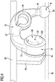
- the release position locking device 240 shown comprises, for example, a locking body 244 arranged in a bore 242 in the actuating body 52 and movable in a locking direction parallel to the bore 242, which is acted upon by a spring unit 246 in the direction of a locking position and which thus moves from a locking release position into the Can pass into the latching position and engage in a latching receptacle 252 in the cover 104 designed as a latching bore if the actuating body 52 is in the position shown in FIG Fig. 8 and 9 shown release position is.
- the spring 246 acts on the latching body 244 in the direction of the cover 104, the latching body 244 having no latching action as long as it slides along the inside 108 of the lid 104 when the actuating body 52 is moved outside the latching receptacle 252.
- a sensing body 254 is arranged in the locking receptacle 252, which scans a flange side 258 of the end flange 198 facing the cover 104 with a probe 256, whereby the flange side 258 has a recess 262, in which the probe 256 of the probe body 254 engages when the latter is intended to allow the locking body 244 to be locked with the locking bore 252.
- the depression 262 merges with a ramp 264 into a latching releasing surface 266 which is higher than the depression 262. whereby the ramp 264 increasingly acts on the probe 256 of the probe body 254 starting from the recess 262 in the direction of the locking body 244 and thus the probe body 254 increasingly displaces the locking body 244 out of the locking receptacle 52 in the direction of the actuating body 252, when the probe head 256 has reached the catch release surface 266, as in Fig. 16 Shown in dashed lines, the probe body 254 is displaced so far in the direction of the actuating body that its end face 268 opposite the probe head 256 is flush with the inside 108 of the cover 104.
- the latching of the actuating body 52 in the release position is released by means of the latching body 244 when the working position A is reached, so that the actuating body 52 then rotates into the rotational blocking position due to the force of the torsion spring 114 and thus the pivot bearing body 14 in this position relative to the guide body 40 rotatably fixed.
- the position of the bore 242 guiding the latching body 244, as well as the latching receptacle 252 and the position of the latching releasing surface 266 are selected such that the probe 256 of the sensing element 254 reaches the latching releasing surface 266 immediately before the working position A is reached, and thus the sensing element 254 detaches the latching body 244 the locking receptacle 252 moved out and thereby the locking of the actuating body 52 in its release position immediately before Reaching or at the latest when the working position is reached, so that even in the working position A, the rotary blocking bodies 54 can engage in the receptacles 60, which are aligned in this position with the guide receptacles 56, and can fix the pivot bearing body 14 in a rotationally fixed manner relative to the guide body 40.
- a rest position locking device 270 which has a locking body 274 provided in the cover 104 in a bore 272, which is acted upon by a spring element 276, for example arranged in the bore 272, in the direction of a locking direction parallel to the bore 272 and in the direction of the end flange 198 and engages in a remaining receptacle 282 formed as a locking bore in the end flange 198 when the pivot bearing body 14 is in the rest position.
- the spring element 276 constantly acts on the latching body 274 in the direction of the flange side 258 of the end flange 198 facing the cover 104, wherein engagement of the latching body 274 in the latching receptacle 282 is only possible if the pivot bearing body 14 has the rotational position corresponding to the rest position R relative to the guide body Has reached 40.
- a sensing body 284 is provided in the latching receptacle 282, which protrudes with a probe 286 over the end flange 198 in the direction of one of the ends 232 of one of the drive arms 196, as in FIG Fig. 18 shown.
- the probe 286 only engage in a recess 288 in one of the ends 232 if, as in FIG Fig. 18 shown, the end 232a bears against the contact body 226a, which is the case when the end 232a, by acting on the contact body 226a, has moved the swivel bearing body 14 and thus the ball neck 10 into the rest position.
- the depression 288 is further provided with a ramp 292, which becomes effective when the end 232a of the drive arm 196a moves from the contact body 226a in the direction of the contact body 228a.
- the ramp 292 acts on the probe 286 in such a way that the probe body 284 is pushed into the detent receptacle 282 until it has pushed the detent body 274 out of its rest position in the detent bore 282 and moved into a release position, one of the probe head 286 Opposing end surface 294 of the probe body 284 is flush with the flange side 258, so that the latching body 274 can no longer fix the pivot bearing body 14 with the end flange 198 relative to the cover 104, but rather the latching body 274 is in its release position and the end flange 198 can rotate freely allows the pivot bearing body 14 relative to the guide body 40, in particular to the cover 104 thereof.
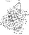
- a securing device 300 is provided in the guide body 40, in particular in the area of the torsion spring receptacle 112, which has a securing body 302, which according to Fig. 20 and 21 in the guide body 40, in particular in the area of the torsion spring receptacle 112, is guided over more than half a circumferential side and projects into the torsion spring receptacle 112 with a securing body segment 304, but does not interact with the torsion spring 114.
- the securing body 302 extends between the ring gear 142 of the planetary gear 130 and the actuating body 52 in such a way that the securing body 302 engages with the securing body segment 304 projecting radially into the torsion spring receptacle 112 either in one unlocking position with one end 306 in a recess 308 in the hollow gear 142, as in Fig. 11 shown, or engages in a securing position with one end 312 in a recess 314 in the actuating body 52, as in Fig. 10 and Fig. 20 shown.
- the securing body 302 remains in this securing position, for example in FIG Fig. 20 is shown, the rotational blocking body in its rotational blocking position.
- the recess 308 is arranged in such a way that an engagement of the securing body 302 with the end 306 in the recess 308 is only possible if the ring gear 142 is rotated using the clearance through the drive slots 156 and the drive fingers, without the actuating body 52 has rotated, so that the actuating body 52 can subsequently be moved out of the rotational blocking position by rotating the ring gear 142 further while rotatingly acting on the drive sleeve 122.
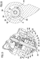
- the actuating body 52 is rotated by the ring gear 142 out of the rotational blocking position in the direction of its release position, namely until the release position is reached and the release position latching device 240 of the actuating body 52 takes effect and locks it in the release position relative to the guide body 40 in the manner described, as shown in FIG Fig. 15 is shown.
- the rest locking device 270 becomes active, namely in that the locking body 274 is able to engage in the locking bore 282 and to move the sensing body in the direction of the depression 288 and to allow it to enter the ends 232 of the drive arms 196.
- the swivel bearing body 14 is thus locked in the rotational position corresponding to the rest position R of the ball neck 10 by the rest position locking device 270.
Landscapes
- Engineering & Computer Science (AREA)
- Transportation (AREA)
- Mechanical Engineering (AREA)
- Rolling Contact Bearings (AREA)
- Mechanical Operated Clutches (AREA)
- Retarders (AREA)
- Lock And Its Accessories (AREA)
- Pivots And Pivotal Connections (AREA)
Claims (15)
- Attelage de remorque comprenant un col de rotule (10), déplaçable entre une position de travail (A) et une position de repos (R), avec un corps de palier pivotant (14) agencé contre une première extrémité (12) et une rotule d'attelage (18) agencée contre une seconde extrémité (16), une unité de palier pivotant (20) agencée de manière fixe contre le véhicule, au moyen de laquelle le corps de palier pivotant (14) est reçu de façon à pouvoir être pivoté autour d'un axe de pivotement (22) entre la position de travail (A) et la position de repos (R), et un dispositif de blocage en rotation (50) avec au moins deux corps de blocage en rotation (54) qui sont guidés de façon déplaçable au moyen d'un corps de guidage (40) dans une direction de guidage (58) avec au moins une composante dans une direction radiale, dans lequel les corps de blocage en rotation dans la position de travail (A) peuvent être amenés, par un déplacement dans la direction de guidage (58), dans une position de blocage en rotation (54), et sont en prise dans celle-ci avec un logement (60) dans le corps de palier pivotant (14) afin de bloquer un déplacement pivotant du corps de palier pivotant (14) autour de l'axe de pivotement (22) par rapport au corps de guidage (40), et peuvent être amenés dans une position de libération et sont dans celle-ci hors de prise avec le logement (60) respectif, et avec un corps d'actionnement (52) présentant pour chacun des corps de blocage en rotation (54) respectivement une surface de calage (66) se déroulant transversalement à la direction de guidage (58) et agencé en rotation autour de l'axe de pivotement (22), par le déplacement en rotation duquel corps d'actionnement dans une direction d'actionnement (72) les au moins deux corps de blocage en rotation (54) peuvent être déplacés et sollicités dans la direction de guidage (58),
caractérisé en ce qu'est prévu, indépendant du dispositif de blocage en rotation (50), un dispositif d'encliquetage en position de repos (270) qui dans une position de libération autorise un déplacement du corps de palier pivotant (14) par rapport au corps de guidage (40) et dans une position d'encliquetage en position de repos établit le corps de palier pivotant (14) solidairement en rotation par rapport au corps de guidage (40), et au moins dans la position de rotation correspondant à la position de repos (R) du corps de palier pivotant (14) solidairement en rotation passe automatiquement dans la position d'encliquetage du fait d'un élément de ressort (276) prévu dans celui-ci. - Attelage de remorque selon la revendication 1, caractérisé en ce que, lorsqu'est atteinte la position de rotation correspondant à la position de repos (R) du corps de palier pivotant (14), le dispositif d'encliquetage en position de repos (270) passe automatiquement dans la position d'encliquetage du fait d'un élément de ressort (276) prévu dans celui-ci.
- Attelage de remorque selon la revendication 1 ou 2, caractérisé en ce que le dispositif d'encliquetage en position de repos (270) peut être libéré en fonction d'un état fonctionnel déterminé de l'attelage de remorque, en ce qu'en particulier au début d'un pivotement du corps de palier pivotant (14) le dispositif d'encliquetage en position de repos (270) peut être libéré de la position de repos (R) vers la position de travail (A).
- Attelage de remorque selon la revendication 3, caractérisé en ce que le dispositif d'encliquetage en position de repos (270) peut être libéré par une unité d'entraînement (182) pouvant être entraînée électriquement.
- Attelage de remorque selon l'une des revendications 3 à 4, caractérisé en ce qu'une unité d'entraînement (182) prévue pour faire pivoter le col de rotule (10) transfère, via un entraînement pivotant pour le col de rotule (10), le dispositif d'encliquetage en position de repos (270) dans la position de libération, en ce qu'en particulier avant un pivotement du corps de palier pivotant (14), l'entraînement pivotant transfère le dispositif d'encliquetage en position de repos (270) dans la position de libération.
- Attelage de remorque selon l'une des revendications précédentes, caractérisé en ce que le dispositif d'encliquetage en position de repos (270) comprend un corps d'encliquetage (274) agencé dans l'un des corps (14, 40) et déplaçable dans une direction d'encliquetage, lequel corps d'encliquetage peut être amené en prise avec un logement d'encliquetage (282) agencé dans un autre des corps (14, 40), en ce qu'en particulier le corps d'encliquetage (274) déplaçable dans la direction d'encliquetage est agencé dans le corps de guidage (40) et en ce que le logement d'encliquetage (282) est agencé dans le corps de palier pivotant (14).
- Attelage de remorque selon la revendication 6, caractérisé en ce que la direction d'encliquetage se déroule en parallèle de l'axe de pivotement (22).
- Attelage de remorque selon l'une des revendications précédentes, caractérisé en ce qu'au logement d'encliquetage (282) est affecté un corps de libération d'encliquetage (284) qui lors d'un actionnement refoule le corps d'encliquetage (274) hors du logement d'encliquetage (282), en ce qu'en particulier le corps de libération d'encliquetage (284) peut être actionné par un entraînement pivotant pour le corps de palier pivotant (14) et en ce qu'en particulier, pour faire pivoter le corps de palier pivotant (14), l'entraînement pivotant peut être déplacé de la position de repos (R) dans la position de travail (A) tout d'abord en course libre par rapport au corps de palier pivotant (14) puis fait pivoter le corps de palier pivotant (14) entre la position de repos (R) et la position de travail (A), en ce qu'en particulier le dispositif d'encliquetage en position de repos (270) est transféré par l'entraînement pivotant pendant la course libre de la position d'encliquetage au repos dans la position de libération.
- Attelage de remorque selon l'une des revendications précédentes, caractérisé en ce qu'un dispositif d'encliquetage en position de libération (240) est prévu, lequel dans une position de libération du corps d'actionnement (52) est déplaçable entre une position de libération d'encliquetage libérant un déplacement du corps d'actionnement (52) par rapport au corps de guidage (40) et une position d'encliquetage immobilisant le corps d'actionnement (52) par rapport au corps de guidage (40) et au moins dans la position de libération du corps d'actionnement (52) est sollicité par un élément de ressort dans la direction de la position d'encliquetage.
- Attelage de remorque selon la revendication 9, caractérisé en ce que le dispositif d'encliquetage en position de libération (240) dans la position de libération du corps d'actionnement (52) passe automatiquement dans la position d'encliquetage à partir du moment où le corps de palier pivotant (14) a quitté la position de rotation correspondant à la position de travail (A).
- Attelage de remorque selon la revendication 9 ou 10, caractérisé en ce que le dispositif d'encliquetage en position de libération (240), lorsqu'est atteinte au moins une position fonctionnelle de l'attelage de remorque, passe de la position d'encliquetage dans la position de libération d'encliquetage, en ce qu'en particulier le dispositif d'encliquetage en position de libération (240) passe, en fonction d'au moins une position de rotation déterminée du corps de palier pivotant (14), de la position d'encliquetage dans la position de libération d'encliquetage et/ou en ce qu'en particulier le dispositif d'encliquetage en position de libération (240) passe, lorsqu'est atteinte au moins une position de rotation prédéfinie du corps de palier pivotant (14), de la position d'encliquetage dans la position de libération d'encliquetage.
- Attelage de remorque selon la revendication 11, caractérisé en ce que le dispositif d'encliquetage en position de libération (240), lorsqu'est atteinte la au moins une position de rotation prédéfinie du corps de palier pivotant (14), passe, commandé mécaniquement, de la position d'encliquetage dans la position de libération d'encliquetage.
- Attelage de remorque selon l'une des revendications précédentes, caractérisé en ce que les corps de blocage en rotation (54) sont agencés autour du corps d'actionnement (52), en ce qu'en particulier le corps d'actionnement (52) présente des surfaces de calage (66) s'étendant selon une plage angulaire autour de l'axe de pivotement (22) et variant dans sa distance radiale par rapport à l'axe de pivotement (22), en ce qu'en particulier le corps de blocage en rotation (54) est guidé par un corps de guidage (40) se raccordant au corps de palier pivotant (14) dans une direction radiale et en ce qu'en particulier le corps de guidage (40) présente une douille de guidage (44) avec le logement de guidage (56) pour le corps de blocage en rotation (54) respectif.
- Attelage de remorque selon l'une des revendications précédentes, caractérisé en ce que le corps de guidage (40) fait partie de l'unité de palier pivotant (20) agencée de manière fixe contre le véhicule, en ce qu'en particulier le corps de guidage (40) forme un palier pivotant pour le corps de palier pivotant (14), et en ce qu'en particulier un palier pour le corps d'actionnement (52) est raccordé au corps de guidage (40).
- Attelage de remorque selon l'une des revendications précédentes, caractérisé en ce que le corps d'actionnement (52) est entouré par le corps de guidage (40) et en ce que le corps de palier pivotant (14) enserre le corps de guidage (40), en ce qu'en particulier le corps de palier pivotant (14) forme un corps extérieur situé à l'extérieur l'unité de palier pivotant (20) et entourant celle-ci, lequel corps extérieur est agencé de façon non coulissante par rapport à l'unité de palier pivotant (20) dans la direction de l'axe de pivotement (22), en ce qu'en particulier la première extrémité du col de rotule (10) est appliquée contre le corps extérieur (14) et en ce qu'en particulier le corps de palier pivotant (14) forme un corps extérieur situé à l'extérieur du dispositif de blocage en rotation (50) et entourant celui-ci, lequel corps extérieur est agencé de façon non coulissante par rapport au corps de guidage (40) dans la direction de l'axe de pivotement (22).
Applications Claiming Priority (1)
| Application Number | Priority Date | Filing Date | Title |
|---|---|---|---|
| DE102015115357.2A DE102015115357A1 (de) | 2015-09-11 | 2015-09-11 | Anhängekupplung |
Publications (2)
| Publication Number | Publication Date |
|---|---|
| EP3141406A1 EP3141406A1 (fr) | 2017-03-15 |
| EP3141406B1 true EP3141406B1 (fr) | 2020-03-25 |
Family
ID=56889009
Family Applications (2)
| Application Number | Title | Priority Date | Filing Date |
|---|---|---|---|
| EP16187841.8A Active EP3141406B1 (fr) | 2015-09-11 | 2016-09-08 | Attelage |
| EP16187840.0A Active EP3141405B1 (fr) | 2015-09-11 | 2016-09-08 | Attelage |
Family Applications After (1)
| Application Number | Title | Priority Date | Filing Date |
|---|---|---|---|
| EP16187840.0A Active EP3141405B1 (fr) | 2015-09-11 | 2016-09-08 | Attelage |
Country Status (3)
| Country | Link |
|---|---|
| US (1) | US10189323B2 (fr) |
| EP (2) | EP3141406B1 (fr) |
| DE (1) | DE102015115357A1 (fr) |
Families Citing this family (23)
| Publication number | Priority date | Publication date | Assignee | Title |
|---|---|---|---|---|
| EP3379222B1 (fr) | 2017-03-22 | 2020-12-30 | Methode Electronics Malta Ltd. | Ensemble de capteur à base magnétoélastique |
| CN108328234B (zh) * | 2018-01-26 | 2024-09-17 | 苏州博众智能机器人有限公司 | 防松动料车运输机器人 |
| US11014417B2 (en) | 2018-02-27 | 2021-05-25 | Methode Electronics, Inc. | Towing systems and methods using magnetic field sensing |
| US11135882B2 (en) | 2018-02-27 | 2021-10-05 | Methode Electronics, Inc. | Towing systems and methods using magnetic field sensing |
| EP3758959B1 (fr) | 2018-02-27 | 2025-11-05 | Methode Electronics, Inc. | Systèmes et procédés de remorquage utilisant la détection magnétique |
| US11084342B2 (en) | 2018-02-27 | 2021-08-10 | Methode Electronics, Inc. | Towing systems and methods using magnetic field sensing |
| US11221262B2 (en) | 2018-02-27 | 2022-01-11 | Methode Electronics, Inc. | Towing systems and methods using magnetic field sensing |
| US11491832B2 (en) | 2018-02-27 | 2022-11-08 | Methode Electronics, Inc. | Towing systems and methods using magnetic field sensing |
| DE102018124518A1 (de) * | 2018-10-04 | 2020-04-09 | ACPS Automotive GmbH | Anhängekupplung |
| DE102019129346A1 (de) * | 2019-10-30 | 2021-05-06 | ACPS Automotive GmbH | Anhängekupplung |
| DE102019129347A1 (de) | 2019-10-30 | 2021-05-06 | ACPS Automotive GmbH | Anhängekupplung |
| DE102020111468A1 (de) | 2020-04-27 | 2021-10-28 | ACPS Automotive GmbH | Anhängekupplung |
| DE102020111469A1 (de) * | 2020-04-27 | 2021-10-28 | ACPS Automotive GmbH | Anhängekupplung |
| DE102020114231A1 (de) * | 2020-05-27 | 2021-12-02 | ACPS Automotive GmbH | Anhängevorrichtung |
| CZ309084B6 (cs) * | 2020-07-07 | 2022-01-19 | Brano A.S. | Výklopné tažné zařízení |
| DE102020134913A1 (de) | 2020-11-03 | 2022-05-05 | Westfalia-Automotive Gmbh | Anhängekupplung mit einer Fixiereinrichtung |
| DE102020128980A1 (de) | 2020-11-03 | 2022-05-05 | Westfalia-Automotive Gmbh | Anhängekupplung mit einer Verriegelungseinrichtung |
| DE112022002547A5 (de) * | 2021-07-06 | 2024-03-07 | Westfalia-Automotive Gmbh | Anhängekupplung mit Betätigungskonturen und Widerlagerkonturen |
| CN215621229U (zh) * | 2021-07-26 | 2022-01-25 | 浙江致优汽车科技有限公司 | 一种拖车联接器 |
| DE102021121092A1 (de) | 2021-08-13 | 2023-02-16 | ACPS Automotive GmbH | Anhängekupplung |
| DE102022114954A1 (de) | 2022-06-14 | 2023-12-14 | ACPS Automotive GmbH | Anhängekupplung |
| CN115675689B (zh) * | 2022-12-26 | 2023-12-01 | 河南兰兴电力机械有限公司 | 一种防脱牵引型agv小车 |
| DE102024111707A1 (de) * | 2024-03-11 | 2025-09-11 | ACPS Automotive GmbH | Anbaueinheit |
Family Cites Families (4)
| Publication number | Priority date | Publication date | Assignee | Title |
|---|---|---|---|---|
| DE19858978C5 (de) * | 1998-12-19 | 2012-06-06 | Westfalia-Automotive Gmbh | Schwenkbare Anhängerkupplung für Kraftfahrzeuge |
| DE102005032474A1 (de) | 2005-07-07 | 2007-01-11 | Oris Fahrzeugteile Hans Riehle Gmbh | Anhängevorrichtung |
| DE102005056217A1 (de) * | 2005-11-25 | 2007-06-06 | Jaeger Cartronix Gmbh | Antriebseinheit für eine Anhängerkupplung |
| DE102006035261A1 (de) * | 2006-07-29 | 2008-01-31 | Scambia Industrial Developments Aktiengesellschaft | Anhängekupplung |
-
2015
- 2015-09-11 DE DE102015115357.2A patent/DE102015115357A1/de not_active Ceased
-
2016
- 2016-09-08 EP EP16187841.8A patent/EP3141406B1/fr active Active
- 2016-09-08 EP EP16187840.0A patent/EP3141405B1/fr active Active
- 2016-09-09 US US15/261,323 patent/US10189323B2/en active Active
Non-Patent Citations (1)
| Title |
|---|
| None * |
Also Published As
| Publication number | Publication date |
|---|---|
| EP3141405A1 (fr) | 2017-03-15 |
| EP3141405B1 (fr) | 2020-06-10 |
| EP3141406A1 (fr) | 2017-03-15 |
| DE102015115357A1 (de) | 2017-03-16 |
| US10189323B2 (en) | 2019-01-29 |
| US20170072753A1 (en) | 2017-03-16 |
Similar Documents
| Publication | Publication Date | Title |
|---|---|---|
| EP3141406B1 (fr) | Attelage | |
| EP3815936B1 (fr) | Crochet d'attelage | |
| EP2261066B1 (fr) | Dispositif de remorque | |
| EP2141034B2 (fr) | Attelage | |
| EP3904129B1 (fr) | Accouplement de remorque | |
| EP2920020B1 (fr) | Dispositif de verrouillage permettant de verrouiller des connecteurs électriques mâles | |
| EP3904128B1 (fr) | Accouplement de remorque | |
| DE19961975C1 (de) | Verriegelungsvorrichtung | |
| DE3616122C2 (de) | Lenk- und Zündschloß | |
| EP3784855B1 (fr) | Serrure de véhicule automobile | |
| EP1491369B1 (fr) | Attelage pour vehicules | |
| EP4292838A1 (fr) | Attelage de remorque | |
| WO2013020541A1 (fr) | Frein de stationnement | |
| DE102021104132B4 (de) | Betätigungsvorrichtung für eine an einem bauteil beweglich gelagerte klappe sowie ein bauteil mit einer solchen betätigungsvorrichtung | |
| EP0823342B1 (fr) | Attelage de remorque | |
| DE102022122865A1 (de) | Anhängekupplung | |
| DE102024123336A1 (de) | Anhängekupplung | |
| EP0791707A2 (fr) | Serrure pour véhicule automobile |
Legal Events
| Date | Code | Title | Description |
|---|---|---|---|
| PUAI | Public reference made under article 153(3) epc to a published international application that has entered the european phase |
Free format text: ORIGINAL CODE: 0009012 |
|
| STAA | Information on the status of an ep patent application or granted ep patent |
Free format text: STATUS: THE APPLICATION HAS BEEN PUBLISHED |
|
| AK | Designated contracting states |
Kind code of ref document: A1 Designated state(s): AL AT BE BG CH CY CZ DE DK EE ES FI FR GB GR HR HU IE IS IT LI LT LU LV MC MK MT NL NO PL PT RO RS SE SI SK SM TR |
|
| AX | Request for extension of the european patent |
Extension state: BA ME |
|
| STAA | Information on the status of an ep patent application or granted ep patent |
Free format text: STATUS: REQUEST FOR EXAMINATION WAS MADE |
|
| 17P | Request for examination filed |
Effective date: 20170824 |
|
| RBV | Designated contracting states (corrected) |
Designated state(s): AL AT BE BG CH CY CZ DE DK EE ES FI FR GB GR HR HU IE IS IT LI LT LU LV MC MK MT NL NO PL PT RO RS SE SI SK SM TR |
|
| RAP1 | Party data changed (applicant data changed or rights of an application transferred) |
Owner name: BOSAL ACPS HOLDING 2 B.V. |
|
| REG | Reference to a national code |
Ref country code: DE Ref legal event code: R079 Ref document number: 502016009248 Country of ref document: DE Free format text: PREVIOUS MAIN CLASS: B60D0001540000 Ipc: B60D0001060000 |
|
| GRAP | Despatch of communication of intention to grant a patent |
Free format text: ORIGINAL CODE: EPIDOSNIGR1 |
|
| STAA | Information on the status of an ep patent application or granted ep patent |
Free format text: STATUS: GRANT OF PATENT IS INTENDED |
|
| RIC1 | Information provided on ipc code assigned before grant |
Ipc: B60D 1/06 20060101AFI20190531BHEP Ipc: B60D 1/54 20060101ALI20190531BHEP Ipc: B60D 1/62 20060101ALI20190531BHEP |
|
| INTG | Intention to grant announced |
Effective date: 20190628 |
|
| RAP1 | Party data changed (applicant data changed or rights of an application transferred) |
Owner name: ACPS AUTOMOTIVE GMBH |
|
| GRAS | Grant fee paid |
Free format text: ORIGINAL CODE: EPIDOSNIGR3 |
|
| GRAJ | Information related to disapproval of communication of intention to grant by the applicant or resumption of examination proceedings by the epo deleted |
Free format text: ORIGINAL CODE: EPIDOSDIGR1 |
|
| GRAL | Information related to payment of fee for publishing/printing deleted |
Free format text: ORIGINAL CODE: EPIDOSDIGR3 |
|
| STAA | Information on the status of an ep patent application or granted ep patent |
Free format text: STATUS: REQUEST FOR EXAMINATION WAS MADE |
|
| GRAP | Despatch of communication of intention to grant a patent |
Free format text: ORIGINAL CODE: EPIDOSNIGR1 |
|
| STAA | Information on the status of an ep patent application or granted ep patent |
Free format text: STATUS: GRANT OF PATENT IS INTENDED |
|
| INTC | Intention to grant announced (deleted) | ||
| INTG | Intention to grant announced |
Effective date: 20191204 |
|
| GRAA | (expected) grant |
Free format text: ORIGINAL CODE: 0009210 |
|
| STAA | Information on the status of an ep patent application or granted ep patent |
Free format text: STATUS: THE PATENT HAS BEEN GRANTED |
|
| AK | Designated contracting states |
Kind code of ref document: B1 Designated state(s): AL AT BE BG CH CY CZ DE DK EE ES FI FR GB GR HR HU IE IS IT LI LT LU LV MC MK MT NL NO PL PT RO RS SE SI SK SM TR |
|
| REG | Reference to a national code |
Ref country code: GB Ref legal event code: FG4D Free format text: NOT ENGLISH |
|
| REG | Reference to a national code |
Ref country code: AT Ref legal event code: REF Ref document number: 1248171 Country of ref document: AT Kind code of ref document: T Effective date: 20200415 Ref country code: IE Ref legal event code: FG4D Free format text: LANGUAGE OF EP DOCUMENT: GERMAN |
|
| REG | Reference to a national code |
Ref country code: DE Ref legal event code: R096 Ref document number: 502016009248 Country of ref document: DE |
|
| REG | Reference to a national code |
Ref country code: NL Ref legal event code: FP |
|
| PG25 | Lapsed in a contracting state [announced via postgrant information from national office to epo] |
Ref country code: FI Free format text: LAPSE BECAUSE OF FAILURE TO SUBMIT A TRANSLATION OF THE DESCRIPTION OR TO PAY THE FEE WITHIN THE PRESCRIBED TIME-LIMIT Effective date: 20200325 Ref country code: NO Free format text: LAPSE BECAUSE OF FAILURE TO SUBMIT A TRANSLATION OF THE DESCRIPTION OR TO PAY THE FEE WITHIN THE PRESCRIBED TIME-LIMIT Effective date: 20200625 Ref country code: RS Free format text: LAPSE BECAUSE OF FAILURE TO SUBMIT A TRANSLATION OF THE DESCRIPTION OR TO PAY THE FEE WITHIN THE PRESCRIBED TIME-LIMIT Effective date: 20200325 |
|
| PG25 | Lapsed in a contracting state [announced via postgrant information from national office to epo] |
Ref country code: LV Free format text: LAPSE BECAUSE OF FAILURE TO SUBMIT A TRANSLATION OF THE DESCRIPTION OR TO PAY THE FEE WITHIN THE PRESCRIBED TIME-LIMIT Effective date: 20200325 Ref country code: SE Free format text: LAPSE BECAUSE OF FAILURE TO SUBMIT A TRANSLATION OF THE DESCRIPTION OR TO PAY THE FEE WITHIN THE PRESCRIBED TIME-LIMIT Effective date: 20200325 Ref country code: HR Free format text: LAPSE BECAUSE OF FAILURE TO SUBMIT A TRANSLATION OF THE DESCRIPTION OR TO PAY THE FEE WITHIN THE PRESCRIBED TIME-LIMIT Effective date: 20200325 Ref country code: GR Free format text: LAPSE BECAUSE OF FAILURE TO SUBMIT A TRANSLATION OF THE DESCRIPTION OR TO PAY THE FEE WITHIN THE PRESCRIBED TIME-LIMIT Effective date: 20200626 Ref country code: BG Free format text: LAPSE BECAUSE OF FAILURE TO SUBMIT A TRANSLATION OF THE DESCRIPTION OR TO PAY THE FEE WITHIN THE PRESCRIBED TIME-LIMIT Effective date: 20200625 |
|
| REG | Reference to a national code |
Ref country code: LT Ref legal event code: MG4D |
|
| PG25 | Lapsed in a contracting state [announced via postgrant information from national office to epo] |
Ref country code: LT Free format text: LAPSE BECAUSE OF FAILURE TO SUBMIT A TRANSLATION OF THE DESCRIPTION OR TO PAY THE FEE WITHIN THE PRESCRIBED TIME-LIMIT Effective date: 20200325 Ref country code: EE Free format text: LAPSE BECAUSE OF FAILURE TO SUBMIT A TRANSLATION OF THE DESCRIPTION OR TO PAY THE FEE WITHIN THE PRESCRIBED TIME-LIMIT Effective date: 20200325 Ref country code: SM Free format text: LAPSE BECAUSE OF FAILURE TO SUBMIT A TRANSLATION OF THE DESCRIPTION OR TO PAY THE FEE WITHIN THE PRESCRIBED TIME-LIMIT Effective date: 20200325 Ref country code: PT Free format text: LAPSE BECAUSE OF FAILURE TO SUBMIT A TRANSLATION OF THE DESCRIPTION OR TO PAY THE FEE WITHIN THE PRESCRIBED TIME-LIMIT Effective date: 20200818 Ref country code: RO Free format text: LAPSE BECAUSE OF FAILURE TO SUBMIT A TRANSLATION OF THE DESCRIPTION OR TO PAY THE FEE WITHIN THE PRESCRIBED TIME-LIMIT Effective date: 20200325 Ref country code: IS Free format text: LAPSE BECAUSE OF FAILURE TO SUBMIT A TRANSLATION OF THE DESCRIPTION OR TO PAY THE FEE WITHIN THE PRESCRIBED TIME-LIMIT Effective date: 20200725 Ref country code: SK Free format text: LAPSE BECAUSE OF FAILURE TO SUBMIT A TRANSLATION OF THE DESCRIPTION OR TO PAY THE FEE WITHIN THE PRESCRIBED TIME-LIMIT Effective date: 20200325 |
|
| REG | Reference to a national code |
Ref country code: DE Ref legal event code: R097 Ref document number: 502016009248 Country of ref document: DE |
|
| PG25 | Lapsed in a contracting state [announced via postgrant information from national office to epo] |
Ref country code: ES Free format text: LAPSE BECAUSE OF FAILURE TO SUBMIT A TRANSLATION OF THE DESCRIPTION OR TO PAY THE FEE WITHIN THE PRESCRIBED TIME-LIMIT Effective date: 20200325 Ref country code: IT Free format text: LAPSE BECAUSE OF FAILURE TO SUBMIT A TRANSLATION OF THE DESCRIPTION OR TO PAY THE FEE WITHIN THE PRESCRIBED TIME-LIMIT Effective date: 20200325 Ref country code: DK Free format text: LAPSE BECAUSE OF FAILURE TO SUBMIT A TRANSLATION OF THE DESCRIPTION OR TO PAY THE FEE WITHIN THE PRESCRIBED TIME-LIMIT Effective date: 20200325 |
|
| PLBE | No opposition filed within time limit |
Free format text: ORIGINAL CODE: 0009261 |
|
| STAA | Information on the status of an ep patent application or granted ep patent |
Free format text: STATUS: NO OPPOSITION FILED WITHIN TIME LIMIT |
|
| PG25 | Lapsed in a contracting state [announced via postgrant information from national office to epo] |
Ref country code: PL Free format text: LAPSE BECAUSE OF FAILURE TO SUBMIT A TRANSLATION OF THE DESCRIPTION OR TO PAY THE FEE WITHIN THE PRESCRIBED TIME-LIMIT Effective date: 20200325 |
|
| 26N | No opposition filed |
Effective date: 20210112 |
|
| PG25 | Lapsed in a contracting state [announced via postgrant information from national office to epo] |
Ref country code: MC Free format text: LAPSE BECAUSE OF FAILURE TO SUBMIT A TRANSLATION OF THE DESCRIPTION OR TO PAY THE FEE WITHIN THE PRESCRIBED TIME-LIMIT Effective date: 20200325 |
|
| REG | Reference to a national code |
Ref country code: CH Ref legal event code: PL |
|
| PG25 | Lapsed in a contracting state [announced via postgrant information from national office to epo] |
Ref country code: SI Free format text: LAPSE BECAUSE OF FAILURE TO SUBMIT A TRANSLATION OF THE DESCRIPTION OR TO PAY THE FEE WITHIN THE PRESCRIBED TIME-LIMIT Effective date: 20200325 |
|
| REG | Reference to a national code |
Ref country code: BE Ref legal event code: MM Effective date: 20200930 |
|
| PG25 | Lapsed in a contracting state [announced via postgrant information from national office to epo] |
Ref country code: LU Free format text: LAPSE BECAUSE OF NON-PAYMENT OF DUE FEES Effective date: 20200908 |
|
| PG25 | Lapsed in a contracting state [announced via postgrant information from national office to epo] |
Ref country code: LI Free format text: LAPSE BECAUSE OF NON-PAYMENT OF DUE FEES Effective date: 20200930 Ref country code: IE Free format text: LAPSE BECAUSE OF NON-PAYMENT OF DUE FEES Effective date: 20200908 Ref country code: BE Free format text: LAPSE BECAUSE OF NON-PAYMENT OF DUE FEES Effective date: 20200930 Ref country code: CH Free format text: LAPSE BECAUSE OF NON-PAYMENT OF DUE FEES Effective date: 20200930 |
|
| PG25 | Lapsed in a contracting state [announced via postgrant information from national office to epo] |
Ref country code: TR Free format text: LAPSE BECAUSE OF FAILURE TO SUBMIT A TRANSLATION OF THE DESCRIPTION OR TO PAY THE FEE WITHIN THE PRESCRIBED TIME-LIMIT Effective date: 20200325 Ref country code: MT Free format text: LAPSE BECAUSE OF FAILURE TO SUBMIT A TRANSLATION OF THE DESCRIPTION OR TO PAY THE FEE WITHIN THE PRESCRIBED TIME-LIMIT Effective date: 20200325 Ref country code: CY Free format text: LAPSE BECAUSE OF FAILURE TO SUBMIT A TRANSLATION OF THE DESCRIPTION OR TO PAY THE FEE WITHIN THE PRESCRIBED TIME-LIMIT Effective date: 20200325 |
|
| PG25 | Lapsed in a contracting state [announced via postgrant information from national office to epo] |
Ref country code: MK Free format text: LAPSE BECAUSE OF FAILURE TO SUBMIT A TRANSLATION OF THE DESCRIPTION OR TO PAY THE FEE WITHIN THE PRESCRIBED TIME-LIMIT Effective date: 20200325 Ref country code: AL Free format text: LAPSE BECAUSE OF FAILURE TO SUBMIT A TRANSLATION OF THE DESCRIPTION OR TO PAY THE FEE WITHIN THE PRESCRIBED TIME-LIMIT Effective date: 20200325 |
|
| REG | Reference to a national code |
Ref country code: DE Ref legal event code: R081 Ref document number: 502016009248 Country of ref document: DE Owner name: ACPS AUTOMOTIVE GMBH, DE Free format text: FORMER OWNER: ACPS AUTOMOTIVE GMBH, 71706 MARKGROENINGEN, DE |
|
| REG | Reference to a national code |
Ref country code: AT Ref legal event code: MM01 Ref document number: 1248171 Country of ref document: AT Kind code of ref document: T Effective date: 20210908 |
|
| PG25 | Lapsed in a contracting state [announced via postgrant information from national office to epo] |
Ref country code: AT Free format text: LAPSE BECAUSE OF NON-PAYMENT OF DUE FEES Effective date: 20210908 |
|
| P01 | Opt-out of the competence of the unified patent court (upc) registered |
Effective date: 20230517 |
|
| PGFP | Annual fee paid to national office [announced via postgrant information from national office to epo] |
Ref country code: DE Payment date: 20250919 Year of fee payment: 10 |
|
| PGFP | Annual fee paid to national office [announced via postgrant information from national office to epo] |
Ref country code: NL Payment date: 20250918 Year of fee payment: 10 |
|
| PGFP | Annual fee paid to national office [announced via postgrant information from national office to epo] |
Ref country code: GB Payment date: 20250919 Year of fee payment: 10 |
|
| PGFP | Annual fee paid to national office [announced via postgrant information from national office to epo] |
Ref country code: FR Payment date: 20250922 Year of fee payment: 10 |
|
| PGFP | Annual fee paid to national office [announced via postgrant information from national office to epo] |
Ref country code: CZ Payment date: 20250903 Year of fee payment: 10 |