EP3141408A1 - Radführungslenker für ein kraftfahrzeug - Google Patents
Radführungslenker für ein kraftfahrzeug Download PDFInfo
- Publication number
- EP3141408A1 EP3141408A1 EP16001965.9A EP16001965A EP3141408A1 EP 3141408 A1 EP3141408 A1 EP 3141408A1 EP 16001965 A EP16001965 A EP 16001965A EP 3141408 A1 EP3141408 A1 EP 3141408A1
- Authority
- EP
- European Patent Office
- Prior art keywords
- radführungslenker
- supporting structure
- louver
- guiding device
- side wall
- Prior art date
- Legal status (The legal status is an assumption and is not a legal conclusion. Google has not performed a legal analysis and makes no representation as to the accuracy of the status listed.)
- Granted
Links
Images


Classifications
-
- B—PERFORMING OPERATIONS; TRANSPORTING
- B60—VEHICLES IN GENERAL
- B60G—VEHICLE SUSPENSION ARRANGEMENTS
- B60G7/00—Pivoted suspension arms; Accessories thereof
- B60G7/001—Suspension arms, e.g. constructional features
-
- B—PERFORMING OPERATIONS; TRANSPORTING
- B62—LAND VEHICLES FOR TRAVELLING OTHERWISE THAN ON RAILS
- B62D—MOTOR VEHICLES; TRAILERS
- B62D35/00—Vehicle bodies characterised by streamlining
- B62D35/02—Streamlining the undersurfaces
-
- B—PERFORMING OPERATIONS; TRANSPORTING
- B60—VEHICLES IN GENERAL
- B60G—VEHICLE SUSPENSION ARRANGEMENTS
- B60G2200/00—Indexing codes relating to suspension types
- B60G2200/10—Independent suspensions
- B60G2200/14—Independent suspensions with lateral arms
- B60G2200/154—Independent suspensions with lateral arms the lateral arm having an L-shape
-
- B—PERFORMING OPERATIONS; TRANSPORTING
- B60—VEHICLES IN GENERAL
- B60G—VEHICLE SUSPENSION ARRANGEMENTS
- B60G2204/00—Indexing codes related to suspensions per se or to auxiliary parts
- B60G2204/10—Mounting of suspension elements
- B60G2204/20—Mounting of accessories, e.g. pump, compressor
-
- B—PERFORMING OPERATIONS; TRANSPORTING
- B60—VEHICLES IN GENERAL
- B60G—VEHICLE SUSPENSION ARRANGEMENTS
- B60G2204/00—Indexing codes related to suspensions per se or to auxiliary parts
- B60G2204/40—Auxiliary suspension parts; Adjustment of suspensions
-
- B—PERFORMING OPERATIONS; TRANSPORTING
- B60—VEHICLES IN GENERAL
- B60G—VEHICLE SUSPENSION ARRANGEMENTS
- B60G2206/00—Indexing codes related to the manufacturing of suspensions: constructional features, the materials used, procedures or tools
- B60G2206/01—Constructional features of suspension elements, e.g. arms, dampers, springs
- B60G2206/10—Constructional features of arms
-
- B—PERFORMING OPERATIONS; TRANSPORTING
- B60—VEHICLES IN GENERAL
- B60G—VEHICLE SUSPENSION ARRANGEMENTS
- B60G2206/00—Indexing codes related to the manufacturing of suspensions: constructional features, the materials used, procedures or tools
- B60G2206/01—Constructional features of suspension elements, e.g. arms, dampers, springs
- B60G2206/10—Constructional features of arms
- B60G2206/122—Constructional features of arms the arm having L-shape
-
- B—PERFORMING OPERATIONS; TRANSPORTING
- B60—VEHICLES IN GENERAL
- B60G—VEHICLE SUSPENSION ARRANGEMENTS
- B60G2206/00—Indexing codes related to the manufacturing of suspensions: constructional features, the materials used, procedures or tools
- B60G2206/01—Constructional features of suspension elements, e.g. arms, dampers, springs
- B60G2206/70—Materials used in suspensions
- B60G2206/71—Light weight materials
- B60G2206/7104—Thermoplastics
-
- B—PERFORMING OPERATIONS; TRANSPORTING
- B60—VEHICLES IN GENERAL
- B60G—VEHICLE SUSPENSION ARRANGEMENTS
- B60G2206/00—Indexing codes related to the manufacturing of suspensions: constructional features, the materials used, procedures or tools
- B60G2206/01—Constructional features of suspension elements, e.g. arms, dampers, springs
- B60G2206/80—Manufacturing procedures
- B60G2206/82—Joining
Definitions
- the invention relates to a Rad arrangementslenker for a motor vehicle, comprising at least one wheel-side connection point and one or more body-side connection points and connecting these attachment points structural structure with a pointing in the forward direction flank.
- components of the wheel suspension which are arranged near the ground in particular are increasingly exposed to an incident flow through the airstream and thus influence the air resistance coefficient of the motor vehicle.
- these components are mainly protected by surrounding components from direct flow, so that there is less pronounced this problem.
- the present invention has for its object to reduce by simple means caused by a vehicle suspension air resistance of a motor vehicle.
- the Rad arrangementslenker invention comprises at least one wheel-side connection point and one or more body-side connection points and connecting these attachment structures structure with a pointing in the forward direction flank and is characterized in particular by the fact that on the pointing forward in the direction of travel flank of the structure an air guiding device is provided, which is configured is to simultaneously direct a portion of the flow of the Rad Equipmentslenkers on the structure structure and a portion of the flow under the structure structure through.
- the solution according to the invention is particularly suitable for vehicles in which, due to the design, individual wheel guide links are particularly exposed in the flow.
- the support structure in a downstream of the air guide in the direction of flow area adjacent to the air guide have a profile cross-section in the vehicle transverse direction, which is closed up and down.
- flow separations and turbulences are reduced in the course of the flow around the structure of the structure and the air resistance coefficient is further improved.
- the air guiding device when viewed in the installed position in the vehicle transverse direction in the profile cross section, may have a curvature projecting in the forward direction of travel, which continuously merges into the course of an upwardly pointing side wall of the supporting structure. This favors, above all, the course of the flow over the upward-pointing side wall of the supporting structure.
- the upwardly facing side wall of the supporting structure be designed such that it falls against the forward direction of travel to the louver in its ground level.
- the air guide when viewed in installation position in the vehicle transverse direction in profile cross section with its lower edge over a downwardly facing side wall of the structure support, the supernatant in the vertical direction less than 1/4 of the profile height of the structure in the transition to the louver is.
- the air resistance can be further reduced in the case of a correspondingly predefined structural structure. It is also possible to completely avoid such a projection, so that the curvature of the air guiding device as on the upwardly facing side wall continuously merges into a downwardly facing side wall of the supporting structure.
- the louver is attached to the structure of the structure.
- the louver can be made of plastic, whereas the structure of the structure consists of metal.
- the attachment of such a separate air guiding device can basically be carried out in any desired manner on the supporting structure.
- a particularly advantageous possibility consists in verklipsen the louver with the pointing in the forward direction edge of the structure structure.
- Verklipsen can also be done elsewhere.
- the air guiding device can be integrally formed on the supporting structure.
- the air guiding device can be formed on only one of the shell elements in order to simplify the manufacture and assembly of the structural structure.
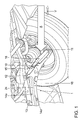
- FIG. 1 a first embodiment of a Rad enclosureslenkers invention 10 is shown in the installed position on a motor vehicle 1.
- a Rad Equipmentslenker usually supports a wheel of a motor vehicle against its structure.
- 10 terms such as top, bottom, front, rear or transverse are used in the following description of the wheel control arm, these are to be understood in each case based on the usual and intended installation position on the motor vehicle.
- arranged near the ground wheel guide arm 10 may be exposed to the flow A through the wind and thus adversely affect the drag coefficient of a motor vehicle.
- the Rad enclosureslenker 10 is exemplified as a triangular wishbone.
- the following explanations can be equally applied to other types of Rad enclosureslenkern.
- the wheel guide link 10 of the first embodiment accordingly comprises at least one wheel-side attachment point 11 and one or more, in the present case two body-side attachment points 12 and 13. These attachment points 11, 12 and 13 are interconnected by a support structure 14.
- the supporting structure 14 is double-shelled and comprises an upper shell element 14a and a lower shell element 14b, which are connected to one another and enclose a cavity.
- the structural structure 14 is double-shelled and comprises an upper shell element 14a and a lower shell element 14b, which are connected to one another and enclose a cavity.
- a different type of design of the structural structure 14 is possible.
- the structural structure 14 has an edge 15 pointing in the forward direction of travel V, which lies in the flow A.
- a louver 16th which is configured to simultaneously pass part of the flow A of the wheel guide arm 10 over the support structure 14 and part of the flow under the structure 14, as shown in FIG FIG. 5 can be seen.
- the air impinging on the wheel guide arm 10 is thus guided by both in the forward direction of travel V on the Rad Equipmentslenker 10 louver 16 both above and below the Rad arrangementslenkers 10 over.
- the proportion of the flow, which is guided over the Rad Equipmentslenker 10, and the proportion, which is passed under the Rad Equipmentslenker 10 can be adjusted.
- louver 16 causes a significant reduction of areas with detached flow and thus less turbulence of the flow along and behind the Rad arrangementslenker 10, resulting in a significantly reduced air resistance for the Rad arrangementslenker 10 with louver 16.
- the support structure 14 is not performed with an open profile cross-section.
- the structural structure 14 is presently formed with a predominantly closed profile cross-section.
- the structural structure 14 has accordingly to the flank 15 subsequent upper and lower side walls 17 and 18. At least in one of the louver 16 downstream in the direction of flow, which adjoins the louver 16, the profile cross-section of the structure 14 should be closed in the vehicle transverse direction up and down.
- FIG. 5 It can also be seen that, when viewed in the installation position in the vehicle transverse direction in the profile cross-section, the air-guiding device 16 has a curvature 16a projecting in the forward direction of travel, which merges continuously into the course of the upward-pointing side wall 17 of the structure.
- the upwardly facing side wall 17 of the supporting structure 14 can fall against the forward direction of travel V toward the louver 16 in its ground level.
- the air guide 16 is when viewed in installation position in the vehicle transverse direction in the profile cross-section (see. FIG. 5 ) with its lower edge 16b over the downwardly facing side wall 18 of the structure 14 structure before something.
- the projection of the lower edge 16b is relatively small and is in the vertical direction at most 1/4 of the profile height of the structural structure 14 in the transition to the louver 16.
- FIG. 4 shows, thereby the flow behavior under the Rad Equipmentslenker 10 is improved.
- such a supernatant can also be completely eliminated, so that, as on the upper side wall 17, there is also a continuous and therefore non-abrupt transition to the lower side wall 18.
- the louver 16 is attached to the structure 14, whereby a large design freedom is available for them.
- the louver can be made of a different material than the structure of the structure.
- other fastening techniques may be used.
- 16 lugs 16c can be integrally formed on the louver 16, which engage with the upper side wall 17 and the lower side wall 18 of the supporting structure 14.
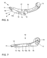
- the louver 16 is clipped with the pointing in the forward direction edge 15 of the structure 15 structure.
- the Verklipsung 19 is located in this case in the vehicle transverse direction laterally adjacent to the vault 16a projecting in the forward direction of travel.
- an attachment can in principle also be made in other ways.
- louver 16 integrally on the support structure 14, whereby a separate component and its attachment omitted.
- the louver 16 may be formed on only one of the shell elements.
- the pointing in the forward direction flank 15 as part of the upper shell member 14a with a pointing in the direction of curvature 16a for example, according to the vaults in the Figures 2 and 6 be executed.
Landscapes
- Engineering & Computer Science (AREA)
- Mechanical Engineering (AREA)
- Chemical & Material Sciences (AREA)
- Combustion & Propulsion (AREA)
- Transportation (AREA)
- Body Structure For Vehicles (AREA)
- Platform Screen Doors And Railroad Systems (AREA)
Abstract
Description
- Die Erfindung bezieht sich auf einen Radführungslenker für ein Kraftfahrzeug, umfassend mindestens eine radseitige Anbindungsstelle und eine oder mehrere aufbauseitige Anbindungsstellen sowie eine diese Anbindungsstellen verbindende Tragwerkstruktur mit einer in Vorwärtsfahrtrichtung weisenden Flanke.
- Derartige Radführungslenker sind im Kraftfahrzeugbau allgemein bekannt und kommen dort in einer Vielzahl von Varianten zum Einsatz.
- Bei Kraftfahrzeugen mit größerer Bodenhöhe, beispielsweise leichten Nutzkraftfahrzeugen, sind insbesondere in Bodennähe angeordnete Komponenten der Radaufhängung verstärkt einer Anströmung durch den Fahrtwind ausgesetzt und beeinflussen somit den Luftwiderstandbeiwert des Kraftfahrzeugs. Bei herkömmlichen Personenkraftfahrzeugen sind diese Komponenten überwiegend durch umliegende Bauteile vor einer unmittelbaren Anströmung geschützt, so dass dort diese Problematik weniger stark ausgeprägt ist.
- Der vorliegenden Erfindung liegt die Aufgabe zugrunde, mit einfachen Mitteln den durch eine Fahrzeugradaufhängung bewirkten Luftwiderstand eines Kraftfahrzeugs zu verringern.
- Diese Aufgabe wird durch einen Radführungslenker gemäß Patentanspruch 1 gelöst. Der erfindungsgemäße Radführungslenker umfasst mindestens eine radseitige Anbindungsstelle und eine oder mehrere aufbauseitige Anbindungsstellen sowie eine diese Anbindungsstellen verbindende Tragwerkstruktur mit einer in Vorwärtsfahrtrichtung weisenden Flanke und zeichnet sich insbesondere dadurch aus, dass an der in Vorwärtsfahrtrichtung weisenden Flanke der Tragwerkstruktur eine Luftleiteinrichtung vorgesehen ist, welche derart konfiguriert ist, um gleichzeitig einen Teil der Anströmung des Radführungslenkers über die Tragwerkstruktur und einen Teil der Anströmung unter der Tragwerkstruktur hindurch zu leiten.
- Mit der erfindungsgemäßen Lösung lässt sich mit sehr geringem Aufwand eine überraschend deutliche Verringerung des Luftwiderstandsbeiwerts eines Kraftfahrzeugs erzielen. Der Fahrtwind wird dabei sowohl über dem Radführungslenkers als auch unter diesem vorbei geleitet, wobei die Bereiche abgelöster Strömung, welche den Luftwiderstand erhöhen würden, vermindert werden.
- Die erfindungsgemäße Lösung eignet sich vor allem für Fahrzeuge, bei denen bauartbedingt einzelne Radführungslenker besonders exponiert in der Anströmung stehen.
- Vorteilhafte Ausgestaltungen der Erfindung sind Gegenstand weiterer Patentansprüche.
- So kann beispielsweise die Tragwerkstruktur in einem der Luftleiteinrichtung in Anströmrichtung nachgelagerten Bereich, welcher an die Luftleiteinrichtung angrenzt, einen Profilquerschnitt in Fahrzeugquerrichtung aufweisen, welcher nach oben und unten geschlossen ist. Hierdurch werden im weiteren Verlauf der Umströmung der Tragwerkstruktur Strömungsablösungen und Verwirbelungen reduziert und der Luftwiderstandbeiwert weiter verbessert.
- Gemäß einer vorteilhaften Ausgestaltung kann die Luftleiteinrichtung bei Betrachtung in Einbaulage in Fahrzeugquerrichtung im Profilquerschnitt eine in Vorwärtsfahrtrichtung vorspringende Wölbung aufweisen, welche kontinuierlich in den Verlauf einer nach oben weisenden Seitenwand der Tragwerkstruktur übergeht. Dies begünstigt vor allem den Strömungsverlauf über die nach oben weisende Seitenwand der Tragwerkstruktur hinweg.
- In diesem Zusammenhang kann zur weiteren Verbesserung des Strömungsverhaltens die nach oben weisende Seitenwand der Tragwerkstruktur derart ausgebildet sein, dass diese entgegen der Vorwärtsfahrtrichtung zu der Luftleiteinrichtung hin in ihrer Bodenhöhe abfällt.
- Gemäß einer weiteren vorteilhaften Ausgestaltung der Erfindung kann die Luftleiteinrichtung bei Betrachtung in Einbaulage in Fahrzeugquerrichtung im Profilquerschnitt mit ihrer Unterkante über eine nach unten weisende Seitenwand der Tragwerkstruktur überstehen, wobei der Überstand in Vertikalrichtung kleiner als 1/4 der Profilhöhe der Tragwerkstruktur im Übergang zu der Luftleiteinrichtung ist. Dadurch lässt sich bei einer entsprechend vorgegebenen Tragwerkstruktur der Luftwiderstand weiter reduzieren. Es ist auch möglich, einen solchen Überstand vollständig zu vermeiden, so dass die Wölbung der Luftleiteinrichtung wie an der nach oben weisenden Seitenwand kontinuierlich in eine nach unten weisende Seitenwand der Tragwerkstruktur übergeht.
- In einer Ausführungsvariante ist die Luftleiteinrichtung an der Tragwerkstruktur befestigt.
- Hierdurch ist es möglich, die Luftleiteinrichtung aus einem anderen Material als die Tragwerkstruktur herzustellen. Beispielsweise kann die Luftleiteinrichtung aus Kunststoff gefertigt werden, wohingegen die Tragwerkstruktur aus Metall besteht. Zudem ergibt sich hierdurch insbesondere in fertigungstechnischer Hinsicht ein großer Gestaltungsfreiraum für die Formgebung der Luftleiteinrichtung.
- Die Befestigung einer solchen separaten Luftleiteinrichtung kann grundsätzlich ein beliebiger Art und Weise an der Tragwerkstruktur vorgenommen werden. Eine besonders vorteilhafte Möglichkeit besteht darin, die Luftleiteinrichtung mit der in Vorwärtsfahrtrichtung weisenden Flanke der Tragwerkstruktur zu verklipsen. Ein solches Verklipsen kann auch an anderer Stelle erfolgen. Beispielsweise ist es auch möglich, die Luftleiteinrichtung vor der in Vorwärtsfahrtrichtung weisenden Flanke anzuordnen und jeweils mit einer an dieser anschließenden nach oben weisenden Seitenwand und einer nach unten weisenden Seitenwand der Tragwerkstruktur zu verklipsen.
- In einer weiteren Ausführungsvariante kann die Luftleiteinrichtung integral an der Tragwerkstruktur ausgeformt sein.
- Wird die Tragwerkstruktur zweischalig ausgebildet, wobei deren Schalenelemente in Vertikalrichtung über einander liegen, kann die Luftleiteinrichtung an lediglich einem der Schalenelemente ausgeformt sein, um Fertigung und Zusammenbau der Tragwerkstruktur zu vereinfachen.
- Nachfolgend wird die Erfindung anhand von in der Zeichnung dargestellten Ausführungsbeispielen näher erläutert. Die Zeichnung zeigt in:
- Figur 1
- ein erstes Ausführungsbeispiel eines Radführungslenkers nach der vorliegenden Erfindung in Einbaulage an einem Kraftfahrzeug,
- Figur 2
- eine räumliche Ansicht des Radführungslenkers aus
Figur 1 , - Figur 3
- eine Ansicht des Radführungslenkers aus
Figur 1 in Blickrichtung auf die Luftleiteinrichtung, - Figur 4
- eine Darstellung der Anströmung ohne Luftleiteinrichtung,
- Figur 5
- eine Darstellung der Anströmung des Radführungslenkers des ersten Ausführungsbeispiels mit Luftleiteinrichtung,
- Figur 6
- eine räumliche Ansicht eines Radführungslenkers nach einem zweiten Ausführungsbeispiel, und in
- Figur 7
- eine Ansicht des Radführungslenkers aus
Figur 6 in Blickrichtung auf die Luftleiteinrichtung. - In
Figur 1 ist ein erstes Ausführungsbeispiel eines erfindungsgemäßen Radführungslenkers 10 in Einbaulage an einem Kraftfahrzeug 1 dargestellt. Ein Radführungslenker stützt üblicherweise ein Rad eines Kraftfahrzeugs gegen dessen Aufbau ab. Soweit in der nachfolgenden Beschreibung des Radführungslenkers 10 Begriffe wie oben, unten, vorn, hinten oder quer verwendet werden, sind diese jeweils auf die übliche und bestimmungsgemäßer Einbaulage am Kraftfahrzeug bezogen zu verstehen. - Insbesondere bodennah angeordnete Radführungslenker 10 können der Anströmung A durch den Fahrtwind ausgesetzt sein und damit den Luftwiderstandsbeiwert eines Kraftfahrzeugs ungünstig beeinflussen.
- Bei dem dargestellten ersten Ausführungsbeispiel ist der Radführungslenker 10 beispielhaft als Dreiecksquerlenker dargestellt. Jedoch lassen sich die nachfolgenden Erläuterungen gleichermaßen auch auf andere Typen von Radführungslenkern übertragen.
- Der Radführungslenker 10 des ersten Ausführungsbeispiels umfasst dementsprechend mindestens eine radseitige Anbindungsstelle 11 und eine oder mehrere, vorliegend zwei aufbauseitige Anbindungsstellen 12 und 13. Diese Anbindungsstellen 11, 12 und 13 sind durch eine Tragwerkstruktur 14 miteinander verbunden.
- Die Tragwerkstruktur 14 ist vorliegend zweischalig ausgebildet und umfasst ein oberes Schalenelement 14a und ein unteres Schalenelement 14b, welche miteinander verbunden sind und einen Hohlraum umschließen. Jedoch ist auch einer andersartige Ausgestaltung der Tragwerkstruktur 14 möglich.
- Generell weist die Tragwerkstruktur 14 jedoch eine in Vorwärtsfahrtrichtung V weisenden Flanke 15 auf, welche in der Anströmung A liegt. An dieser Flanke ist eine Luftleiteinrichtung 16 vorgesehen, welche derart konfiguriert ist, um gleichzeitig einen Teil der Anströmung A des Radführungslenkers 10 über die Tragwerkstruktur 14 hinweg und einen Teil der Anströmung unter der Tragwerkstruktur 14 hindurch zu leiten, wie dies in
Figur 5 zu erkennen ist. Die auf den Radführungslenker 10 auftreffende Luft wird somit durch die in Vorwärtsfahrtrichtung V an dem Radführungslenker 10 vorliegende Luftleiteinrichtung 16 sowohl oberhalb als auch unterhalb des Radführungslenkers 10 vorbei geleitet. Über die Profilierung der Luftleiteinrichtung 16 kann der Anteil der Anströmung, welcher über den Radführungslenker 10 geführt wird, und der Anteil, welcher unter dem Radführungslenker 10 hindurchgeführt wird, eingestellt werden. - Wie einem Vergleich der
Figuren 4 und 5 ohne und mit Luftleiteinrichtung 16 entnommen werden kann, bewirkt die Luftleiteinrichtung 16 eine deutliche Verringerung von Bereichen mit abgelöster Strömung und damit eine geringere Verwirbelung der Strömung entlang und hinter dem Radführungslenker 10, wodurch sich für den Radführungslenker 10 mit Luftleiteinrichtung 16 ein deutlich reduzierter Luftwiderstand ergibt. - Für die Umströmung des Radführungslenkers ist es ferner von Vorteil, wenn dessen Tragwerkstruktur 14 nicht mit einem offenen Profilquerschnitt ausgeführt wird. Wie den
Figuren 1 und2 entnommen werden kann, ist die Tragwerkstruktur 14 vorliegend mit einem weit überwiegend geschlossenen Profilquerschnitt ausgebildet. Die Tragwerkstruktur 14 weist dementsprechend an die Flanke 15 anschließende obere und untere Seitenwände 17 und 18 auf. Zumindest in einem der Luftleiteinrichtung 16 in Anströmrichtung nachgelagerten Bereich, welcher an die Luftleiteinrichtung 16 angrenzt, sollte der Profilquerschnitt der Tragwerkstruktur 14 in Fahrzeugquerrichtung nach oben und unten geschlossen sein. -
Figur 5 ist weiter zu entnehmen, dass die Luftleiteinrichtung 16 bei Betrachtung in Einbaulage in Fahrzeugquerrichtung im Profilquerschnitt eine in Vorwärtsfahrtrichtung vorspringende Wölbung 16a aufweist, welche kontinuierlich in den Verlauf der nach oben weisenden Seitenwand 17 der Tragwerkstruktur übergeht. - Zudem kann die nach oben weisende Seitenwand 17 der Tragwerkstruktur 14 entgegen der Vorwärtsfahrtrichtung V zu der Luftleiteinrichtung 16 hin in ihrer Bodenhöhe abfallen.
- Bei dem dargestellten Ausführungsbeispiel steht die Luftleiteinrichtung 16 bei Betrachtung in Einbaulage in Fahrzeugquerrichtung im Profilquerschnitt (vgl.
Figur 5 ) mit ihrer Unterkante 16b über die nach unten weisende Seitenwand 18 der Tragwerkstruktur 14 etwas vor. Der Überstand der Unterkante 16b ist jedoch verhältnismäßig gering und beträgt in Vertikalrichtung maximal 1/4 der Profilhöhe der Tragwerkstruktur 14 im Übergang zu der Luftleiteinrichtung 16. Wie ein Vergleich mitFigur 4 zeigt, wird hierdurch das Strömungsverhalten unter dem Radführungslenker 10 verbessert. Ein solcher Überstand kann jedoch auch vollständig entfallen, so dass sich wie an der oberen Seitenwand 17 auch zu der unteren Seitenwand 18 hin ein kontinuierlicher und damit sprungfreier Übergang ergibt. - Bei dem ersten Ausführungsbeispiel ist die Luftleiteinrichtung 16 an der Tragwerkstruktur 14 befestigt, wodurch für diese ein großer Gestaltungsfreiraum zur Verfügung steht. Zudem kann die Luftleiteinrichtung aus einem anderen Werkstoff als die Tragwerkstruktur gefertigt werden. Insbesondere ist es möglich, die Luftleiteinrichtung 16 als Kunststoffbauteil auszuführen. Letzteres ist vorliegend mit der Tragwerkstruktur 14 verklipst. Jedoch können auch andere Befestigungstechniken zum Einsatz kommen.
- Wie insbesondere den
Figuren 2 und 3 entnommen werden kann, können an die Luftleiteinrichtung 16 Laschen 16c angeformt sein, welche mit der oberen Seitenwand 17 und der unteren Seitenwand 18 der Tragwerkstruktur 14 verrasten. In einer weiteren Ausführungsvariante, welche in denFiguren 6 und 7 dargestellt ist, ist die Luftleiteinrichtung 16 mit der in Vorwärtsfahrtrichtung weisenden Flanke 15 der Tragwerkstruktur 15 verklipst. Die Verklipsung 19 befindet sich in diesem Fall in Fahrzeugquerrichtung seitlich neben der in Vorwärtsfahrtrichtung vorspringenden Wölbung 16a. Wie bereits ausgeführt, kann jedoch eine Befestigung grundsätzlich auch auf andere Art und Weise vorgenommen sein. - Weiterhin ist es möglich, die Luftleiteinrichtung 16 integral an der Tragwerkstruktur 14 auszuformen, wodurch ein separates Bauteil und dessen Befestigung entfallen. Beispielsweise kann an einer zweischaligen Tragwerkstruktur 14 mit übereinanderliegendem oberen und unteren Schalenelement 14a und 14b, wie in den
Figuren 1 bis 3 dargestellt, die Luftleiteinrichtung 16 an lediglich einem der Schalenelemente ausgeformt sein. Vorliegend kann beispielsweise die in Vorwärtsfahrtrichtung weisende Flanke 15 als Bestandteil des oberen Schalenelements 14a mit einer in Fahrtrichtung weisenden Wölbung 16a, beispielsweise entsprechend den Wölbungen in denFiguren 2 und6 ausgeführt werden. - Die Erfindung wurde vorstehend anhand eines Ausführungsbeispiels und weiterer Abwandlungen näher erläutert. Insbesondere können technische Einzelmerkmale, welche oben im Kontext weiterer Einzelmerkmale erläutert wurden, unabhängig von diesen sowie in Kombination mit weiteren Einzelmerkmalen verwirklicht werden, auch wenn dies nicht ausdrücklich beschrieben ist, solange dies technisch möglich ist. Die Erfindung ist daher ausdrücklich nicht auf die beschriebenen Ausführungsbeispiele und Abwandlungen beschränkt, sondern umfasst alle durch die Patentansprüche definierten Ausgestaltungen.
-
- 1
- Kraftfahrzeug
- 10
- Radführungslenker
- 11
- radseitige Anbindungsstelle
- 12
- aufbauseitige Anbindungsstellen
- 13
- aufbauseitige Anbindungsstellen
- 14
- Tragwerkstruktur
- 14a
- oberes Schalenelement
- 14b
- unteres Schalenelement
- 15
- Flanke
- 16
- Luftleiteinrichtung
- 16a
- Wölbung
- 16b
- Unterkante
- 16c
- Lasche
- 17
- nach oben weisende Seitenwand
- 18
- nach unten weisende Seitenwand
- 19
- Verklipsung
- A
- Anströmung
- V
- Vorwärtsfahrtrichtung
Claims (10)
- Radführungslenker (10) für ein Kraftfahrzeug, umfassend
mindestens eine radseitige Anbindungsstelle (11) und eine oder mehrere aufbauseitige Anbindungsstellen (12,13) sowie eine diese Anbindungsstellen (11, 12,13) verbindende Tragwerkstruktur (14) mit einer in Vorwärtsfahrtrichtung weisenden Flanke (15),
dadurch gekennzeichnet, dass
an der in Vorwärtsfahrtrichtung weisenden Flanke (15) eine Luftleiteinrichtung (16) vorgesehen ist, welche derart konfiguriert ist, um gleichzeitig einen Teil der Anströmung des Radführungslenkers (10) über die Tragwerkstruktur (14) und einen Teil der Anströmung unter der Tragwerkstruktur (14) hindurch zu leiten. - Radführungslenker nach Anspruch 1, dadurch gekennzeichnet, dass die Tragwerkstruktur (14) in einem der Luftleiteinrichtung (16) in Anströmrichtung nachgelagerten Bereich, welcher an die Luftleiteinrichtung (16) angrenzt, einen Profilquerschnitt in Fahrzeugquerrichtung aufweist, welcher nach oben und unten geschlossen ist.
- Radführungslenker nach Anspruch 1 oder 2, dadurch gekennzeichnet, dass die Luftleiteinrichtung (16) bei Betrachtung in Einbaulage in Fahrzeugquerrichtung im Profilquerschnitt eine in Vorwärtsfahrtrichtung vorspringende Wölbung (16a) aufweist, welche kontinuierlich in den Verlauf einer nach oben weisenden Seitenwand (17) der Tragwerkstruktur (14) übergeht.
- Radführungslenker nach Anspruch 3, dadurch gekennzeichnet, dass die nach oben weisende Seitenwand (17) der Tragwerkstruktur (14) entgegen der Vorwärtsfahrtrichtung zu der Luftleiteinrichtung (16) hin in ihrer Bodenhöhe abfällt.
- Radführungslenker nach einem der Ansprüche 1 bis 4, dadurch gekennzeichnet, dass die Luftleiteinrichtung (16) bei Betrachtung in Einbaulage in Fahrzeugquerrichtung im Profilquerschnitt mit ihrer Unterkante (16c) über eine nach unten weisende Seitenwand (18) der Tragwerkstruktur (14) übersteht, wobei der Überstand in Vertikalrichtung kleiner als 1/4 der Profilhöhe der Tragwerkstruktur (14) im Übergang zu der Luftleiteinrichtung (16) ist.
- Radführungslenker nach einem der Ansprüche 1 bis 5, dadurch gekennzeichnet, dass die Luftleiteinrichtung (16) an der Tragwerkstruktur (14) befestigt ist.
- Radführungslenker nach Anspruch 6, dadurch gekennzeichnet, dass die Luftleiteinrichtung (16) mit der in Vorwärtsfahrtrichtung weisenden Flanke (15) der Tragwerkstruktur (14) verklipst ist.
- Radführungslenker nach Anspruch 6 oder 7, dadurch gekennzeichnet, dass die Luftleiteinrichtung (16) vor der in Vorwärtsfahrtrichtung weisenden Flanke (15) angeordnet und jeweils mit einer an dieser anschließenden nach oben weisenden Seitenwand (17) und einer nach unten weisenden Seitenwand (18) der Tragwerkstruktur (14) verklipst ist.
- Radführungslenker nach einem der Ansprüche 1 bis 5, dadurch gekennzeichnet, dass die Luftleiteinrichtung (16) integral an der Tragwerkstruktur (14) ausgeformt ist.
- Radführungslenker nach Anspruch 9, dadurch gekennzeichnet, dass die Tragwerkstruktur (14) zweischalig ausgebildet ist, wobei deren Schalenelemente (14a, 14b) in Vertikalrichtung über einander liegen und die Luftleiteinrichtung (16) an lediglich einem der Schalenelemente (14a) ausgeformt ist.
Applications Claiming Priority (1)
| Application Number | Priority Date | Filing Date | Title |
|---|---|---|---|
| DE102015115227.4A DE102015115227A1 (de) | 2015-09-10 | 2015-09-10 | Radführungslenker für ein Kraftfahrzeug |
Publications (2)
| Publication Number | Publication Date |
|---|---|
| EP3141408A1 true EP3141408A1 (de) | 2017-03-15 |
| EP3141408B1 EP3141408B1 (de) | 2020-09-02 |
Family
ID=56936231
Family Applications (1)
| Application Number | Title | Priority Date | Filing Date |
|---|---|---|---|
| EP16001965.9A Active EP3141408B1 (de) | 2015-09-10 | 2016-09-09 | Radführungslenker für ein kraftfahrzeug |
Country Status (3)
| Country | Link |
|---|---|
| EP (1) | EP3141408B1 (de) |
| CN (1) | CN107031324B (de) |
| DE (1) | DE102015115227A1 (de) |
Cited By (3)
| Publication number | Priority date | Publication date | Assignee | Title |
|---|---|---|---|---|
| EP4124478A1 (de) * | 2021-07-28 | 2023-02-01 | Renault s.a.s | Lenker oder dreieckslenker und verfahren zur herstellung eines solchen lenkers oder dreieckslenkers |
| JP2025072087A (ja) * | 2023-10-24 | 2025-05-09 | 豊田鉄工株式会社 | サスペンションアーム |
| US20260097618A1 (en) * | 2023-01-24 | 2026-04-09 | Toyoda Iron Works Co., Ltd. | Suspension arm |
Families Citing this family (1)
| Publication number | Priority date | Publication date | Assignee | Title |
|---|---|---|---|---|
| DE102021100479A1 (de) * | 2021-01-13 | 2022-07-14 | Audi Aktiengesellschaft | Fahrzeugachse mit Luftumlenkelementen und Anschlagschutzen |
Citations (11)
| Publication number | Priority date | Publication date | Assignee | Title |
|---|---|---|---|---|
| DE69102228T2 (de) * | 1990-07-30 | 1994-09-15 | Fiat Auto Spa | Unabhängige Aufhängung für ein Motorfahrzeugrad. |
| DE69108832T2 (de) * | 1990-10-04 | 1995-12-07 | Mac Lean Fogg Lock Nut Co | Endverbindungsglied eines Fahrzeugstabilisatorstabs. |
| DE19738249A1 (de) * | 1997-09-02 | 1999-03-11 | Daimler Benz Ag | Lenker, insbesondere für eine Radaufhängung eines Kraftfahrzeuges |
| DE10252135A1 (de) * | 2002-11-09 | 2004-05-27 | Zf Friedrichshafen Ag | Achsaufhängung in Einzelradaufhängung für Kraftfahrzeuge |
| US6810586B1 (en) * | 1999-11-03 | 2004-11-02 | Raufoss Technology As | Control arm and method for manufacturing |
| US20070096420A1 (en) * | 2005-11-02 | 2007-05-03 | Lounsberry Todd H | Air deflector arrangement for a vehicle |
| JP2009196557A (ja) * | 2008-02-22 | 2009-09-03 | Toyota Motor Corp | サスペンションアームカバー |
| DE102011051575A1 (de) * | 2011-07-05 | 2013-01-10 | Dr. Ing. H.C. F. Porsche Aktiengesellschaft | Gestänge, insbesondere Lenker für eine Radführung eines Kraftfahrzeugs |
| DE102011056161A1 (de) * | 2011-12-08 | 2013-06-13 | Dr.Ing.H.C. F. Porsche Ag | Luftleitvorrichtung |
| DE102014014837A1 (de) * | 2014-10-07 | 2016-04-07 | Audi Ag | Verkleidungsteil für einen Fahrwerkslenker |
| DE102015005501A1 (de) * | 2015-04-30 | 2016-11-03 | Audi Ag | Luftleiteinrichtung für einen Fahrwerkslenker |
Family Cites Families (3)
| Publication number | Priority date | Publication date | Assignee | Title |
|---|---|---|---|---|
| JP3966874B2 (ja) * | 2004-08-23 | 2007-08-29 | 本田技研工業株式会社 | 車両用サスペンション装置 |
| DE102013006253A1 (de) * | 2013-04-11 | 2014-10-16 | Audi Ag | Verfahren zur Herstellung einer Luftleiteinrichtung für einen Fahrwerkslenker und Fahrwerkslenker mit einer Luftleiteinrichtung |
| KR101427079B1 (ko) * | 2013-06-11 | 2014-08-07 | 주식회사 오스템 | 자동차 현가장치용 로어아암 |
-
2015
- 2015-09-10 DE DE102015115227.4A patent/DE102015115227A1/de not_active Withdrawn
-
2016
- 2016-09-09 EP EP16001965.9A patent/EP3141408B1/de active Active
- 2016-09-12 CN CN201610817553.5A patent/CN107031324B/zh active Active
Patent Citations (11)
| Publication number | Priority date | Publication date | Assignee | Title |
|---|---|---|---|---|
| DE69102228T2 (de) * | 1990-07-30 | 1994-09-15 | Fiat Auto Spa | Unabhängige Aufhängung für ein Motorfahrzeugrad. |
| DE69108832T2 (de) * | 1990-10-04 | 1995-12-07 | Mac Lean Fogg Lock Nut Co | Endverbindungsglied eines Fahrzeugstabilisatorstabs. |
| DE19738249A1 (de) * | 1997-09-02 | 1999-03-11 | Daimler Benz Ag | Lenker, insbesondere für eine Radaufhängung eines Kraftfahrzeuges |
| US6810586B1 (en) * | 1999-11-03 | 2004-11-02 | Raufoss Technology As | Control arm and method for manufacturing |
| DE10252135A1 (de) * | 2002-11-09 | 2004-05-27 | Zf Friedrichshafen Ag | Achsaufhängung in Einzelradaufhängung für Kraftfahrzeuge |
| US20070096420A1 (en) * | 2005-11-02 | 2007-05-03 | Lounsberry Todd H | Air deflector arrangement for a vehicle |
| JP2009196557A (ja) * | 2008-02-22 | 2009-09-03 | Toyota Motor Corp | サスペンションアームカバー |
| DE102011051575A1 (de) * | 2011-07-05 | 2013-01-10 | Dr. Ing. H.C. F. Porsche Aktiengesellschaft | Gestänge, insbesondere Lenker für eine Radführung eines Kraftfahrzeugs |
| DE102011056161A1 (de) * | 2011-12-08 | 2013-06-13 | Dr.Ing.H.C. F. Porsche Ag | Luftleitvorrichtung |
| DE102014014837A1 (de) * | 2014-10-07 | 2016-04-07 | Audi Ag | Verkleidungsteil für einen Fahrwerkslenker |
| DE102015005501A1 (de) * | 2015-04-30 | 2016-11-03 | Audi Ag | Luftleiteinrichtung für einen Fahrwerkslenker |
Cited By (4)
| Publication number | Priority date | Publication date | Assignee | Title |
|---|---|---|---|---|
| EP4124478A1 (de) * | 2021-07-28 | 2023-02-01 | Renault s.a.s | Lenker oder dreieckslenker und verfahren zur herstellung eines solchen lenkers oder dreieckslenkers |
| FR3125747A1 (fr) * | 2021-07-28 | 2023-02-03 | Renault S.A.S | Bras ou triangle de suspension et procédé de fabrication d’un tel bras ou triangle de suspension |
| US20260097618A1 (en) * | 2023-01-24 | 2026-04-09 | Toyoda Iron Works Co., Ltd. | Suspension arm |
| JP2025072087A (ja) * | 2023-10-24 | 2025-05-09 | 豊田鉄工株式会社 | サスペンションアーム |
Also Published As
| Publication number | Publication date |
|---|---|
| EP3141408B1 (de) | 2020-09-02 |
| CN107031324A (zh) | 2017-08-11 |
| DE102015115227A1 (de) | 2017-03-16 |
| CN107031324B (zh) | 2022-03-01 |
Similar Documents
| Publication | Publication Date | Title |
|---|---|---|
| EP3116767B1 (de) | Abdeckung für einen fahrwerkslenker | |
| EP2435288B1 (de) | Fahrzeug mit einer luftleiteinrichtung | |
| EP3003835B1 (de) | Kraftfahrzeug mit von einem radgehäuse ausgehenden luftkanal | |
| DE102010036442B4 (de) | Luftleitvorrichtung | |
| DE19958748B4 (de) | Vorrichtung zur Beeinflussung der Luftströmung | |
| DE102010061760B4 (de) | Unterer Aufbau eines hinteren Teils eines Fahrzeugkörpers | |
| WO2015082149A1 (de) | Unterbodenverkleidung für ein zweispuriges kraftfahrzeug sowie zweispuriges kraftfahrzeug mit einer solchen unterbodenverkleidung | |
| DE102016109605B4 (de) | Fahrzeugfrontstruktur | |
| DE102013006253A1 (de) | Verfahren zur Herstellung einer Luftleiteinrichtung für einen Fahrwerkslenker und Fahrwerkslenker mit einer Luftleiteinrichtung | |
| EP3672818B1 (de) | Abdeckteil für ein fahrwerkselement eines kraftfahrzeugs | |
| EP3141408A1 (de) | Radführungslenker für ein kraftfahrzeug | |
| WO2016124458A1 (de) | Fahrwerksbauteil in hybridkonstruktion | |
| DE102014208560A1 (de) | Fahrzeugfrontstruktur | |
| DE102010008348A1 (de) | Fliessheck eines Personenkraftwagens | |
| DE102018114434B4 (de) | Fahrzeugunterkonstruktion | |
| DE102012023586A1 (de) | Windabweiseinrichtung für ein Fahrzeugdach eines Kraftwagens | |
| DE102016113730A1 (de) | Querträger im Kraftfahrzeug | |
| DE102014006757B4 (de) | Fahrzeugfrontstruktur | |
| DE102016215032A1 (de) | Luftleiteinrichtung für ein Kraftfahrzeug | |
| DE102014223054A1 (de) | Fahrzeugkarosserie für ein Fahrzeug | |
| WO2024061421A1 (de) | Strömungsleitstruktur und kraftfahrzeug | |
| DE102015100225A1 (de) | Wasserkastenanordnung für einen Personenkraftwagen | |
| DE102010060613A1 (de) | Trennelement mit Lüftungskanälen | |
| DE102004057899B4 (de) | Fahrzeugklappenanordnung für ein Kraftfahrzeug | |
| DE102016116458A1 (de) | Bug eines Kraftfahrzeugs |
Legal Events
| Date | Code | Title | Description |
|---|---|---|---|
| PUAI | Public reference made under article 153(3) epc to a published international application that has entered the european phase |
Free format text: ORIGINAL CODE: 0009012 |
|
| STAA | Information on the status of an ep patent application or granted ep patent |
Free format text: STATUS: THE APPLICATION HAS BEEN PUBLISHED |
|
| AK | Designated contracting states |
Kind code of ref document: A1 Designated state(s): AL AT BE BG CH CY CZ DE DK EE ES FI FR GB GR HR HU IE IS IT LI LT LU LV MC MK MT NL NO PL PT RO RS SE SI SK SM TR |
|
| AX | Request for extension of the european patent |
Extension state: BA ME |
|
| STAA | Information on the status of an ep patent application or granted ep patent |
Free format text: STATUS: REQUEST FOR EXAMINATION WAS MADE |
|
| 17P | Request for examination filed |
Effective date: 20170822 |
|
| RBV | Designated contracting states (corrected) |
Designated state(s): AL AT BE BG CH CY CZ DE DK EE ES FI FR GB GR HR HU IE IS IT LI LT LU LV MC MK MT NL NO PL PT RO RS SE SI SK SM TR |
|
| GRAP | Despatch of communication of intention to grant a patent |
Free format text: ORIGINAL CODE: EPIDOSNIGR1 |
|
| STAA | Information on the status of an ep patent application or granted ep patent |
Free format text: STATUS: GRANT OF PATENT IS INTENDED |
|
| INTG | Intention to grant announced |
Effective date: 20200604 |
|
| GRAS | Grant fee paid |
Free format text: ORIGINAL CODE: EPIDOSNIGR3 |
|
| RIN1 | Information on inventor provided before grant (corrected) |
Inventor name: PETZOLD, ROUVEN Inventor name: SUMEC, MICHAL Inventor name: KNOTHE, ULRICH |
|
| GRAA | (expected) grant |
Free format text: ORIGINAL CODE: 0009210 |
|
| STAA | Information on the status of an ep patent application or granted ep patent |
Free format text: STATUS: THE PATENT HAS BEEN GRANTED |
|
| AK | Designated contracting states |
Kind code of ref document: B1 Designated state(s): AL AT BE BG CH CY CZ DE DK EE ES FI FR GB GR HR HU IE IS IT LI LT LU LV MC MK MT NL NO PL PT RO RS SE SI SK SM TR |
|
| REG | Reference to a national code |
Ref country code: GB Ref legal event code: FG4D Free format text: NOT ENGLISH |
|
| REG | Reference to a national code |
Ref country code: AT Ref legal event code: REF Ref document number: 1308431 Country of ref document: AT Kind code of ref document: T Effective date: 20200915 Ref country code: CH Ref legal event code: EP |
|
| REG | Reference to a national code |
Ref country code: DE Ref legal event code: R096 Ref document number: 502016010981 Country of ref document: DE |
|
| REG | Reference to a national code |
Ref country code: IE Ref legal event code: FG4D Free format text: LANGUAGE OF EP DOCUMENT: GERMAN |
|
| REG | Reference to a national code |
Ref country code: LT Ref legal event code: MG4D |
|
| PG25 | Lapsed in a contracting state [announced via postgrant information from national office to epo] |
Ref country code: BG Free format text: LAPSE BECAUSE OF FAILURE TO SUBMIT A TRANSLATION OF THE DESCRIPTION OR TO PAY THE FEE WITHIN THE PRESCRIBED TIME-LIMIT Effective date: 20201202 Ref country code: LT Free format text: LAPSE BECAUSE OF FAILURE TO SUBMIT A TRANSLATION OF THE DESCRIPTION OR TO PAY THE FEE WITHIN THE PRESCRIBED TIME-LIMIT Effective date: 20200902 Ref country code: HR Free format text: LAPSE BECAUSE OF FAILURE TO SUBMIT A TRANSLATION OF THE DESCRIPTION OR TO PAY THE FEE WITHIN THE PRESCRIBED TIME-LIMIT Effective date: 20200902 Ref country code: SE Free format text: LAPSE BECAUSE OF FAILURE TO SUBMIT A TRANSLATION OF THE DESCRIPTION OR TO PAY THE FEE WITHIN THE PRESCRIBED TIME-LIMIT Effective date: 20200902 Ref country code: FI Free format text: LAPSE BECAUSE OF FAILURE TO SUBMIT A TRANSLATION OF THE DESCRIPTION OR TO PAY THE FEE WITHIN THE PRESCRIBED TIME-LIMIT Effective date: 20200902 Ref country code: GR Free format text: LAPSE BECAUSE OF FAILURE TO SUBMIT A TRANSLATION OF THE DESCRIPTION OR TO PAY THE FEE WITHIN THE PRESCRIBED TIME-LIMIT Effective date: 20201203 Ref country code: NO Free format text: LAPSE BECAUSE OF FAILURE TO SUBMIT A TRANSLATION OF THE DESCRIPTION OR TO PAY THE FEE WITHIN THE PRESCRIBED TIME-LIMIT Effective date: 20201202 |
|
| REG | Reference to a national code |
Ref country code: NL Ref legal event code: MP Effective date: 20200902 |
|
| PG25 | Lapsed in a contracting state [announced via postgrant information from national office to epo] |
Ref country code: RS Free format text: LAPSE BECAUSE OF FAILURE TO SUBMIT A TRANSLATION OF THE DESCRIPTION OR TO PAY THE FEE WITHIN THE PRESCRIBED TIME-LIMIT Effective date: 20200902 Ref country code: LV Free format text: LAPSE BECAUSE OF FAILURE TO SUBMIT A TRANSLATION OF THE DESCRIPTION OR TO PAY THE FEE WITHIN THE PRESCRIBED TIME-LIMIT Effective date: 20200902 Ref country code: PL Free format text: LAPSE BECAUSE OF FAILURE TO SUBMIT A TRANSLATION OF THE DESCRIPTION OR TO PAY THE FEE WITHIN THE PRESCRIBED TIME-LIMIT Effective date: 20200902 |
|
| PG25 | Lapsed in a contracting state [announced via postgrant information from national office to epo] |
Ref country code: NL Free format text: LAPSE BECAUSE OF FAILURE TO SUBMIT A TRANSLATION OF THE DESCRIPTION OR TO PAY THE FEE WITHIN THE PRESCRIBED TIME-LIMIT Effective date: 20200902 Ref country code: RO Free format text: LAPSE BECAUSE OF FAILURE TO SUBMIT A TRANSLATION OF THE DESCRIPTION OR TO PAY THE FEE WITHIN THE PRESCRIBED TIME-LIMIT Effective date: 20200902 Ref country code: SM Free format text: LAPSE BECAUSE OF FAILURE TO SUBMIT A TRANSLATION OF THE DESCRIPTION OR TO PAY THE FEE WITHIN THE PRESCRIBED TIME-LIMIT Effective date: 20200902 Ref country code: PT Free format text: LAPSE BECAUSE OF FAILURE TO SUBMIT A TRANSLATION OF THE DESCRIPTION OR TO PAY THE FEE WITHIN THE PRESCRIBED TIME-LIMIT Effective date: 20210104 Ref country code: EE Free format text: LAPSE BECAUSE OF FAILURE TO SUBMIT A TRANSLATION OF THE DESCRIPTION OR TO PAY THE FEE WITHIN THE PRESCRIBED TIME-LIMIT Effective date: 20200902 Ref country code: CZ Free format text: LAPSE BECAUSE OF FAILURE TO SUBMIT A TRANSLATION OF THE DESCRIPTION OR TO PAY THE FEE WITHIN THE PRESCRIBED TIME-LIMIT Effective date: 20200902 |
|
| REG | Reference to a national code |
Ref country code: CH Ref legal event code: PL |
|
| PG25 | Lapsed in a contracting state [announced via postgrant information from national office to epo] |
Ref country code: ES Free format text: LAPSE BECAUSE OF FAILURE TO SUBMIT A TRANSLATION OF THE DESCRIPTION OR TO PAY THE FEE WITHIN THE PRESCRIBED TIME-LIMIT Effective date: 20200902 Ref country code: AL Free format text: LAPSE BECAUSE OF FAILURE TO SUBMIT A TRANSLATION OF THE DESCRIPTION OR TO PAY THE FEE WITHIN THE PRESCRIBED TIME-LIMIT Effective date: 20200902 Ref country code: IS Free format text: LAPSE BECAUSE OF FAILURE TO SUBMIT A TRANSLATION OF THE DESCRIPTION OR TO PAY THE FEE WITHIN THE PRESCRIBED TIME-LIMIT Effective date: 20210102 |
|
| REG | Reference to a national code |
Ref country code: DE Ref legal event code: R097 Ref document number: 502016010981 Country of ref document: DE |
|
| REG | Reference to a national code |
Ref country code: BE Ref legal event code: MM Effective date: 20200930 |
|
| PG25 | Lapsed in a contracting state [announced via postgrant information from national office to epo] |
Ref country code: LU Free format text: LAPSE BECAUSE OF NON-PAYMENT OF DUE FEES Effective date: 20200909 Ref country code: SK Free format text: LAPSE BECAUSE OF FAILURE TO SUBMIT A TRANSLATION OF THE DESCRIPTION OR TO PAY THE FEE WITHIN THE PRESCRIBED TIME-LIMIT Effective date: 20200902 Ref country code: MC Free format text: LAPSE BECAUSE OF FAILURE TO SUBMIT A TRANSLATION OF THE DESCRIPTION OR TO PAY THE FEE WITHIN THE PRESCRIBED TIME-LIMIT Effective date: 20200902 |
|
| PLBE | No opposition filed within time limit |
Free format text: ORIGINAL CODE: 0009261 |
|
| STAA | Information on the status of an ep patent application or granted ep patent |
Free format text: STATUS: NO OPPOSITION FILED WITHIN TIME LIMIT |
|
| 26N | No opposition filed |
Effective date: 20210603 |
|
| PG25 | Lapsed in a contracting state [announced via postgrant information from national office to epo] |
Ref country code: SI Free format text: LAPSE BECAUSE OF FAILURE TO SUBMIT A TRANSLATION OF THE DESCRIPTION OR TO PAY THE FEE WITHIN THE PRESCRIBED TIME-LIMIT Effective date: 20200902 Ref country code: IE Free format text: LAPSE BECAUSE OF NON-PAYMENT OF DUE FEES Effective date: 20200909 Ref country code: LI Free format text: LAPSE BECAUSE OF NON-PAYMENT OF DUE FEES Effective date: 20200930 Ref country code: CH Free format text: LAPSE BECAUSE OF NON-PAYMENT OF DUE FEES Effective date: 20200930 Ref country code: DK Free format text: LAPSE BECAUSE OF FAILURE TO SUBMIT A TRANSLATION OF THE DESCRIPTION OR TO PAY THE FEE WITHIN THE PRESCRIBED TIME-LIMIT Effective date: 20200902 Ref country code: BE Free format text: LAPSE BECAUSE OF NON-PAYMENT OF DUE FEES Effective date: 20200930 |
|
| PG25 | Lapsed in a contracting state [announced via postgrant information from national office to epo] |
Ref country code: IT Free format text: LAPSE BECAUSE OF FAILURE TO SUBMIT A TRANSLATION OF THE DESCRIPTION OR TO PAY THE FEE WITHIN THE PRESCRIBED TIME-LIMIT Effective date: 20200902 |
|
| PG25 | Lapsed in a contracting state [announced via postgrant information from national office to epo] |
Ref country code: TR Free format text: LAPSE BECAUSE OF FAILURE TO SUBMIT A TRANSLATION OF THE DESCRIPTION OR TO PAY THE FEE WITHIN THE PRESCRIBED TIME-LIMIT Effective date: 20200902 Ref country code: MT Free format text: LAPSE BECAUSE OF FAILURE TO SUBMIT A TRANSLATION OF THE DESCRIPTION OR TO PAY THE FEE WITHIN THE PRESCRIBED TIME-LIMIT Effective date: 20200902 Ref country code: CY Free format text: LAPSE BECAUSE OF FAILURE TO SUBMIT A TRANSLATION OF THE DESCRIPTION OR TO PAY THE FEE WITHIN THE PRESCRIBED TIME-LIMIT Effective date: 20200902 |
|
| PG25 | Lapsed in a contracting state [announced via postgrant information from national office to epo] |
Ref country code: MK Free format text: LAPSE BECAUSE OF FAILURE TO SUBMIT A TRANSLATION OF THE DESCRIPTION OR TO PAY THE FEE WITHIN THE PRESCRIBED TIME-LIMIT Effective date: 20200902 |
|
| REG | Reference to a national code |
Ref country code: AT Ref legal event code: MM01 Ref document number: 1308431 Country of ref document: AT Kind code of ref document: T Effective date: 20210909 |
|
| PG25 | Lapsed in a contracting state [announced via postgrant information from national office to epo] |
Ref country code: AT Free format text: LAPSE BECAUSE OF NON-PAYMENT OF DUE FEES Effective date: 20210909 |
|
| P01 | Opt-out of the competence of the unified patent court (upc) registered |
Effective date: 20230526 |
|
| PGFP | Annual fee paid to national office [announced via postgrant information from national office to epo] |
Ref country code: DE Payment date: 20250930 Year of fee payment: 10 |
|
| PGFP | Annual fee paid to national office [announced via postgrant information from national office to epo] |
Ref country code: GB Payment date: 20250923 Year of fee payment: 10 |
|
| PGFP | Annual fee paid to national office [announced via postgrant information from national office to epo] |
Ref country code: FR Payment date: 20250926 Year of fee payment: 10 |