EP3141429B1 - Rétroviseur de porte de véhicule - Google Patents
Rétroviseur de porte de véhicule Download PDFInfo
- Publication number
- EP3141429B1 EP3141429B1 EP14891440.1A EP14891440A EP3141429B1 EP 3141429 B1 EP3141429 B1 EP 3141429B1 EP 14891440 A EP14891440 A EP 14891440A EP 3141429 B1 EP3141429 B1 EP 3141429B1
- Authority
- EP
- European Patent Office
- Prior art keywords
- door mirror
- rotation
- protrusion
- shaft
- mirror unit
- Prior art date
- Legal status (The legal status is an assumption and is not a legal conclusion. Google has not performed a legal analysis and makes no representation as to the accuracy of the status listed.)
- Active
Links
- 230000001105 regulatory effect Effects 0.000 claims description 33
- 238000003780 insertion Methods 0.000 description 5
- 230000037431 insertion Effects 0.000 description 5
- 230000000717 retained effect Effects 0.000 description 5
- 238000005406 washing Methods 0.000 description 3
- 230000000694 effects Effects 0.000 description 2
- 230000014759 maintenance of location Effects 0.000 description 2
- 229920003002 synthetic resin Polymers 0.000 description 2
- 239000000057 synthetic resin Substances 0.000 description 2
- 230000033228 biological regulation Effects 0.000 description 1
- 230000006835 compression Effects 0.000 description 1
- 238000007906 compression Methods 0.000 description 1
- 238000010276 construction Methods 0.000 description 1
- 238000009434 installation Methods 0.000 description 1
- 230000002265 prevention Effects 0.000 description 1
- 230000003068 static effect Effects 0.000 description 1
Images




Classifications
-
- B—PERFORMING OPERATIONS; TRANSPORTING
- B60—VEHICLES IN GENERAL
- B60R—VEHICLES, VEHICLE FITTINGS, OR VEHICLE PARTS, NOT OTHERWISE PROVIDED FOR
- B60R1/00—Optical viewing arrangements; Real-time viewing arrangements for drivers or passengers using optical image capturing systems, e.g. cameras or video systems specially adapted for use in or on vehicles
- B60R1/02—Rear-view mirror arrangements
- B60R1/06—Rear-view mirror arrangements mounted on vehicle exterior
- B60R1/076—Rear-view mirror arrangements mounted on vehicle exterior yieldable to excessive external force and provided with an indexed use position
Definitions
- the present invention relates to a vehicular door mirror.
- a door mirror unit is assembled via a shaft to a door mirror base which is fixed to a vehicular side part (a door side).
- the door mirror unit is made turnable at a folded storage position at which a mirror surface faces the door side about the shaft and a deployed use position at which the mirror surface faces a vehicular rear side while a phase is varied at a required angle from the folded storage position.
- a rotation moderation mechanism is provided at a respective one of a shaft and a bearing portion of a door mirror unit so that the deployed use position of the door mirror unit can be appropriately retained.
- a plurality of recessed and protrusion engagement portions to engage the shaft and the bearing portion from each other in a vertical direction are provided on a same planar circumference and to these recessed and protrusion engagement portions, a pressing force in the vertical direction is imparted by a spring so that the recessed and protrusion engagement portions engage with or disengage from each other in a rotation direction due to a rotation operation of the door mirror unit to thereby retain a required rotation position with a sense of moderation.
- Document US 2013/025810 A1 discloses a vehicular door mirror according to the preamble of claim 1.
- Patent Literature 1 Japanese Unexamined Patent Application Publication No. 2011-121560
- the recessed and protrusion engagement portions that are provided at the respective one of the shaft and bearing portion described above are respectively provided at a relative rotation position which corresponds to the deployed use position of the door mirror unit and at a relative rotation position which corresponds to the folded storage position thereof, and the deployed use position and the folded storage position, of the door mirror unit, can be thereby appropriately retained.
- a shaft and its bearing portion are also downsized; and therefore, there may be a case in which it becomes difficult in terms of space requirements to set the recessed and protrusion engagement portion at the rotation position that corresponds to the folded storage position.
- the present invention provides a vehicular door mirror in which an engagement construction to retain a folded storage position can be set at a respective one of a shaft and a door mirror unit without being affected by setting of a rotation moderation mechanism which retains a deployed use position of the door mirror unit.
- a vehicular door mirror according to the present invention is defined by the features of claim 1.
- a protrusion portion of a groove top face of a rotation regulating groove comes into sliding contact with and rides over a protrusion portion at an upper edge of a rotation regulating piece and then these protrusion portions drop and engage, and the folded storage position of the door mirror unit is retained.
- Fig. 1 shows a state of arrangement of a door mirror at a left side of a vehicle.
- the door mirror of the embodiment shown in Fig. 1 is equipped with: a door mirror base 1 which is fixed to a vehicular side part, specifically a door side D of a front door; a shaft 2 which is fixed to the door mirror base 1; and a door mirror unit 3 which has been turnably supported on the door mirror base 1 by means of the shaft 2.
- the door mirror base 1, the shaft 2, and the housing 31 and the bracket 32 of the door mirror unit 3 all are made of an appropriate synthetic resin.
- the door mirror base 1 is equipped with an attachment portion 11 which is securely fixed to the door size D; and an arm portion 12 substantially horizontally overhanging laterally from the attachment portion 11 and supporting the door mirror unit 3 via the shaft 2.
- the shaft 2 is assembled to the door mirror unit 3 in a subsidiary manner, and a lower end thereof is fixed to the arm portion 12 of the door mirror base 1.
- a bearing portion 33 forming a shaft insertion hole 34 is provided at one end of the bracket 32 of the door mirror unit 3.
- An outer circumference of the bearing portion 33 is formed in a substantially semicircular shape which is coaxial to the shaft insertion hole 34.
- a substantially annular rotation regulating groove 37 which is set at a required groove width is formed of: an outer circumferential wall 35 which has been formed on an outer circumference of the substantially semicircular shape; and an inner circumferential wall 36 which has been formed on a hole edge of the shaft insertion hole 34.
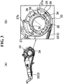
- the rotation regulating groove 37 as shown in Fig. 1 , is partitioned in a shape of a fan by a groove stop end wall 37a to specify a folded storage position P1 of the door mirror unit 3 and a groove stop end wall 37 to specify a maximally unfolded position P3.
- the shaft 2 is integrally erected on an erection base portion surface 22 forming a top face of a substantially cylindrical base portion 21 of which lower side has been opened, and is disposed to be inserted into the bearing hole 34 from a lower side of the bracket 32.
- a plurality of boss portions 21a are protruded, and the boss portions 21a are securely fixed onto the arm portion 12 of the door mirror base 1.
- a rotation regulating piece 23 which engages with the rotation regulating groove 37 on a bottom surface of the bearing portion 33 is integrally erected.
- one groove stop end wall 37a in the rotation regulating groove 37 of the bracket 22 described above is engagingly locked with one side edge of the rotation regulating piece 23, and the folded storage position P1 of the door mirror unit 3 is thereby specified; and the other groove stop end wall 37 is engagingly locked with the other side edge of the rotation regulating piece 23, and the maximally unfolded position P3 is thereby specified.
- a rotation top 4 formed in a shape of a ring is movably disposed to be engagingly inserted in a circumferential direction and in an axial direction.
- the rotation top 4 is made of an appropriate synthetic resin as in the shaft 2 and the bracket 32 or the like.
- a collar 41 which comes into sliding contact with a lower edge of the shaft insertion hole 34 of the bearing portion 33 and an inner circumferential wall 36 that follows the lower edge are formed to be integral with each other.
- a plurality of engagingly locking protrusions 42 are intermittently provided to be integral with one another in a circumferential direction, whereas at an end edge of the inner circumferential wall 36, a plurality of cutout portions 38 with which the engagingly locking protrusions 42 respectively engage are intermittently formed in the circumferential direction.
- the rotation top 4 is rotatable to be integral with the bracket 32 with respect to the shaft 2.
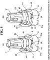
- a plurality of protrusion edge parts 43 are provided in the circumferential direction, whereas on the erection base portion surface 22 of the shaft 2, there is provided a recessed portion 24 for specifying the deployed use position P2 at which the protrusion edge part 43 drops and engages with the erection base portion surface 22 when the door mirror unit 3 has been rotated from the folded storage position P1 to the deployment direction.
- protrusion edge part 43 and recessed portion 24 each form a circumferential end edge in a diagonal manner, so that both of them easily engage with or disengage from each other.
- a coil spring 5 is elastically equipped in a compressed state.
- the coil spring 5 constitutes a rotation moderation mechanism 6 of the door mirror unit 3 together with the rotation top 4 described above; functions as retention of a pressing force of the bearing portion 33 and the rotation top 4 with respect to the erection base portion surface 22 of the shaft 2 and as prevention of a backlash of the door mirror unit 3; and is elastically equipped in a compressed state between a washer 7 which has been disposed on a top face of the bearing portion 33 and a push nut 8 which has been engagingly inserted into and then engagingly fitted to an upper end part of the shaft 2.
- the door mirror unit 3 is manually rotatable with respect to the door mirror base 1, at the folded storage position P1 at which the mirror surface faces the door side about the shaft 2 and at the deployed use position P2 at which the mirror surface faces the vehicular rear side while a phase is varied at a required angle from the folded storage position P1.
- the door mirror unit 3 rotates up to the maximally unfolded position P3 and then a load on the door mirror unit 3 is reduced to avoid damage thereto.
- protrusion portions 25, 39 which respectively ride over, drop, and engage in the course of rotation from the deployed use position P2 to the folded storage position P1 of the door mirror unit 3 and then retain the folded storage position P1.
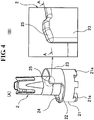
- the protrusion portion 25 of the rotation regulating piece 23 is formed at an upper edge of an end edge side at which the rotation regulating piece 23 engagingly locks with the groove stop end wall 37a that specifies the folded storage position P1 in the rotation regulating groove 37.
- the protrusion portion 39 at the rotation regulating groove 37 side is formed on a groove top face at a position at intervals which are equivalent to a length of the protrusion portion 25 from the groove stop end wall 37a.
- the door mirror unit 3 is slightly lifted up and moved on an axial line of the shaft 2 together with the rotation top 4 against the spring force of the coil spring 5 of the rotation moderation mechanism 6 to thereby permit riding of the respective one of the protrusion portions 25, 39 described above.
- the protrusion portion 39 rides over the protrusion portion 25, the protrusion portion 39 drops and engages in a gap between the protrusion portion 25 and the groove stop end wall 37a due to the spring force of the coil spring 5 (refer to Fig. 6 (A) to Fig. 6 (C) ).
- the respective protrusion portions 25, 39 ride over, drop, and engage, and a sense of click can be thereby felt; and accordingly, it is possible to recognize that a rotation operation leading up to the appropriate folded storage position P1 has completed, and it is also possible to avoid an occurrence of a storage operation failure.
- an angle of rotation between the folded storage position P1 and the deployed use position P2 of the door mirror unit 3 does not need to be set to be so large, and at the periphery of the shaft 2 that is a center of rotation, the A-B strokes of rotation of the rotation top 4 are extremely small.
- the protrusion portions 25, 39 which respectively drop and engage with the respective one of the upper edge of the rotation regulating piece 23 of the shaft 2 and the groove top face of the rotation regulating groove 37 of the bearing portion 33 at the course of rotation from the deployed use position P2 to the folded storage position P1.
- the structure of engagement for retaining the folded storage position P1 can be employed in a reasonable manner in terms of design requirements without being affected by setting of the structure of engagement that is made of the recessed portion 24 and the protrusion edge part 43 for retaining the deployed use position P2 by means of the rotation moderation mechanism 6, and it is possible to provide a vehicular door mirror of which quality is high.
- Fig. 7 shows a second embodiment of the present invention.
- a recessed portion 44 is provided at a central part of a lower edge of the protrusion edge part 43 in the first embodiment.
- an engagingly locking protrusion 26 with which the recessed portion 44 of the protrusion edge part 43 drops and engages is provided at the folded storage position P1 of the door mirror unit 3.
- the recessed portion 44 of the protrusion portion 43 and the engagingly locking protrusion 26 of the erection base portion surface 22 corresponding thereto are small in dimensions in the structural point of view, engaging locking forces thereof are respectively applied to engagingly locking forces of the protrusion portions 25, 39 described previously; and therefore, it is possible to enhance the rotation regulation effect of the door mirror unit 3 in the deployment direction at the folded storage position P1 described previously.
- the door mirror of the manual storage type was shown as an example, it is also possible to apply to a door mirror of an electrically driven storage type.
Landscapes
- Engineering & Computer Science (AREA)
- Multimedia (AREA)
- Mechanical Engineering (AREA)
- Rear-View Mirror Devices That Are Mounted On The Exterior Of The Vehicle (AREA)
Claims (3)
- Rétroviseur de porte de véhicule comprenant:une base de rétroviseur de porte (1) qui est fixée à une partie latérale de véhicule (D);une tige (2) qui est fixée à la base de rétroviseur de porte (1); etune unité de rétroviseur de porte (3) qui peut tourner autour de l'arbre (2) dans une position de repos repliée (P1) et une position d'utilisation déployée (P2) via une partie d'appui (33),dans lequel la partie d'appui (33) est une structure qui est équipée d'une rainure de réglage de rotation (37) sensiblement annulaire sur son côté inférieur, et qui est agencée pour s'engager dans la rainure de réglage de rotation (37) avec une pièce de réglage de rotation (23) prévue au niveau de la tige et dans laquelle un mécanisme de modération de rotation (6) retenant la position d'utilisation déployée (P2) de l'unité de rétroviseur extérieur (3) est prévu au niveau de la tige (2) et de la partie d'appui (33),caractérisé en ce qu'un bord supérieur de la pièce de réglage de rotation (23) et une face supérieure de la rainure de réglage de rotation (37) opposée au bord supérieur de la pièce de réglage de rotation (23) présentent chacune une partie en saillie (25, 39), dans lequel les parties en saillie (25, 39) sont agencées de sorte que la saillie (39) de la face supérieure de la rainure de réglage de rotation (37) chevauche, retombe et s'engage avec la partie en saillie (25) du bord supérieur de la pièce de réglage de rotation (23) lors de la rotation de l'unité de rétroviseur (3) depuis la position d'utilisation déployée (P2) vers la position de repos repliée (P1) et dans laquelle les parties saillantes (25, 39), dans la position engagée conservent la position de repos repliée (P1).
- Rétroviseur de porte de véhicule selon la revendication 1, caractérisé en ce que le mécanisme de modération de rotation (6) comprend:un sommet de rotation (4) en forme d'anneau, qui est disposé de manière mobile pour s'introduire en mettant en prise la tige (2), une rotation du sommet de rotation (4) étant restreinte par rapport à la partie d'appui (33); etun ressort (5) pour comprimer le sommet de rotation (4) contre une surface de la partie base de construction de la tige (22); etqu'une partie de bord en saillie (43) qui est prévue sur une face inférieure du sommet de rotation (4) et une partie en creux (24) qui est prévue sur la surface de la partie de base de construction (22) de la tige (2) sont respectivement capables de retomber et de s'engager l'une dans l'autre au niveau de la position d'utilisation déployée (P2) de l'unité de rétroviseur extérieur (3).
- Rétroviseur de porte de véhicule selon la revendication 2, caractérisé en ce qu'une seconde partie en creux (44) est prévue sur un bord inférieur de la partie de bord en saillie (43) du sommet de rotation (4), et sur la surface de la partie de base de construction (22) de la tige (2), une saillie de verrouillage par engagement (26) avec laquelle la seconde partie en creux (44) de la partie de bord de saillie (43) est configurée pour retomber et s'engager dans la position de repos repliée (P1) de l'unité de rétroviseur extérieur (3).
Applications Claiming Priority (1)
| Application Number | Priority Date | Filing Date | Title |
|---|---|---|---|
| PCT/JP2014/062484 WO2015170404A1 (fr) | 2014-05-09 | 2014-05-09 | Rétroviseur de porte de véhicule |
Publications (3)
| Publication Number | Publication Date |
|---|---|
| EP3141429A1 EP3141429A1 (fr) | 2017-03-15 |
| EP3141429A4 EP3141429A4 (fr) | 2017-12-27 |
| EP3141429B1 true EP3141429B1 (fr) | 2019-08-14 |
Family
ID=54392272
Family Applications (1)
| Application Number | Title | Priority Date | Filing Date |
|---|---|---|---|
| EP14891440.1A Active EP3141429B1 (fr) | 2014-05-09 | 2014-05-09 | Rétroviseur de porte de véhicule |
Country Status (4)
| Country | Link |
|---|---|
| US (1) | US9925923B2 (fr) |
| EP (1) | EP3141429B1 (fr) |
| CN (1) | CN106458098B (fr) |
| WO (1) | WO2015170404A1 (fr) |
Families Citing this family (1)
| Publication number | Priority date | Publication date | Assignee | Title |
|---|---|---|---|---|
| WO2018215336A1 (fr) * | 2017-05-24 | 2018-11-29 | SMR Patents S.à.r.l. | Système de détente de pivot et dispositif de vision arrière équipé dudit système |
Family Cites Families (9)
| Publication number | Priority date | Publication date | Assignee | Title |
|---|---|---|---|---|
| DE10009670B4 (de) * | 2000-02-29 | 2005-08-04 | Bühler Motor GmbH | Außenrückblickspiegel für ein Kraftfahrzeug |
| JP3996441B2 (ja) * | 2002-05-21 | 2007-10-24 | 市光工業株式会社 | 車両用サイドミラー |
| JP2007083839A (ja) * | 2005-09-21 | 2007-04-05 | Tokai Rika Co Ltd | 車両用ミラー装置 |
| JP2008143357A (ja) * | 2006-12-11 | 2008-06-26 | Tokai Rika Co Ltd | 車両用ミラー装置 |
| JP4847311B2 (ja) * | 2006-12-25 | 2011-12-28 | 株式会社東海理化電機製作所 | 車両用ミラー装置 |
| JP2011121560A (ja) | 2009-12-14 | 2011-06-23 | Mitsuba Corp | ドアミラー、およびドアミラーの製造方法 |
| JP6019664B2 (ja) * | 2012-03-28 | 2016-11-02 | 市光工業株式会社 | 車両用アウトサイドミラー装置 |
| CN202656933U (zh) * | 2012-06-19 | 2013-01-09 | 三多乐精密注塑(深圳)有限公司 | 汽车后视镜折叠装置 |
| JP6083274B2 (ja) * | 2013-03-19 | 2017-02-22 | 市光工業株式会社 | 車両用ドアミラー |
-
2014
- 2014-05-09 CN CN201480078677.5A patent/CN106458098B/zh not_active Expired - Fee Related
- 2014-05-09 EP EP14891440.1A patent/EP3141429B1/fr active Active
- 2014-05-09 WO PCT/JP2014/062484 patent/WO2015170404A1/fr not_active Ceased
- 2014-05-09 US US15/309,581 patent/US9925923B2/en not_active Expired - Fee Related
Non-Patent Citations (1)
| Title |
|---|
| None * |
Also Published As
| Publication number | Publication date |
|---|---|
| WO2015170404A1 (fr) | 2015-11-12 |
| CN106458098B (zh) | 2019-12-31 |
| US20170151911A1 (en) | 2017-06-01 |
| EP3141429A4 (fr) | 2017-12-27 |
| CN106458098A (zh) | 2017-02-22 |
| US9925923B2 (en) | 2018-03-27 |
| EP3141429A1 (fr) | 2017-03-15 |
Similar Documents
| Publication | Publication Date | Title |
|---|---|---|
| US10919382B2 (en) | Rotary type extension/retraction device | |
| CN105899745B (zh) | 闩锁装置 | |
| US7594819B2 (en) | Rotary connector | |
| KR101322540B1 (ko) | 압상장치 | |
| EP3135844A1 (fr) | Dispositif trappe | |
| CN102308053B (zh) | 用于固定具有推-推运动机构的致动装置的固定装置 | |
| CA2615174A1 (fr) | Dispositif de verrouillage de direction electrique et methode d'installation | |
| CN105383389B (zh) | 车辆用目视确认装置 | |
| JP6329845B2 (ja) | 回転コネクタ装置 | |
| US11131115B2 (en) | Compression latch with key holding | |
| CN105291907A (zh) | 用于车辆座椅的角度调节装置 | |
| US11110863B2 (en) | Connector arrangement for a motor vehicle rear-view mirror | |
| EP2642617B1 (fr) | Dispositif rotatif de connexion | |
| US9925923B2 (en) | Vehicular door mirror | |
| JP2021500262A (ja) | 特に自動車の外部視覚ユニットの固定構造 | |
| CN103908190B (zh) | 用于坐便器座圈的减振器锁定机构 | |
| CN112997368B (zh) | 车辆用连接器 | |
| JP6557172B2 (ja) | 飲料容器 | |
| EP2065169A1 (fr) | Mécanisme de blocage de talon de vulcanisateur de pneus | |
| CN107887768B (zh) | 旋转连接器 | |
| JP2008080946A (ja) | キャップ装置 | |
| JP6083274B2 (ja) | 車両用ドアミラー | |
| EP2923900A1 (fr) | Dispositif de direction | |
| US20160036184A1 (en) | Lock member for a rotary connector device | |
| US11251666B2 (en) | Motor and electrical product |
Legal Events
| Date | Code | Title | Description |
|---|---|---|---|
| STAA | Information on the status of an ep patent application or granted ep patent |
Free format text: STATUS: THE INTERNATIONAL PUBLICATION HAS BEEN MADE |
|
| PUAI | Public reference made under article 153(3) epc to a published international application that has entered the european phase |
Free format text: ORIGINAL CODE: 0009012 |
|
| STAA | Information on the status of an ep patent application or granted ep patent |
Free format text: STATUS: REQUEST FOR EXAMINATION WAS MADE |
|
| 17P | Request for examination filed |
Effective date: 20161108 |
|
| AK | Designated contracting states |
Kind code of ref document: A1 Designated state(s): AL AT BE BG CH CY CZ DE DK EE ES FI FR GB GR HR HU IE IS IT LI LT LU LV MC MK MT NL NO PL PT RO RS SE SI SK SM TR |
|
| AX | Request for extension of the european patent |
Extension state: BA ME |
|
| DAX | Request for extension of the european patent (deleted) | ||
| A4 | Supplementary search report drawn up and despatched |
Effective date: 20171127 |
|
| RIC1 | Information provided on ipc code assigned before grant |
Ipc: B60R 1/06 20060101AFI20171121BHEP |
|
| GRAP | Despatch of communication of intention to grant a patent |
Free format text: ORIGINAL CODE: EPIDOSNIGR1 |
|
| STAA | Information on the status of an ep patent application or granted ep patent |
Free format text: STATUS: GRANT OF PATENT IS INTENDED |
|
| INTG | Intention to grant announced |
Effective date: 20190321 |
|
| GRAS | Grant fee paid |
Free format text: ORIGINAL CODE: EPIDOSNIGR3 |
|
| GRAA | (expected) grant |
Free format text: ORIGINAL CODE: 0009210 |
|
| STAA | Information on the status of an ep patent application or granted ep patent |
Free format text: STATUS: THE PATENT HAS BEEN GRANTED |
|
| AK | Designated contracting states |
Kind code of ref document: B1 Designated state(s): AL AT BE BG CH CY CZ DE DK EE ES FI FR GB GR HR HU IE IS IT LI LT LU LV MC MK MT NL NO PL PT RO RS SE SI SK SM TR |
|
| REG | Reference to a national code |
Ref country code: GB Ref legal event code: FG4D |
|
| REG | Reference to a national code |
Ref country code: CH Ref legal event code: EP Ref country code: AT Ref legal event code: REF Ref document number: 1166641 Country of ref document: AT Kind code of ref document: T Effective date: 20190815 |
|
| REG | Reference to a national code |
Ref country code: IE Ref legal event code: FG4D |
|
| REG | Reference to a national code |
Ref country code: DE Ref legal event code: R096 Ref document number: 602014051963 Country of ref document: DE |
|
| REG | Reference to a national code |
Ref country code: NL Ref legal event code: MP Effective date: 20190814 |
|
| REG | Reference to a national code |
Ref country code: LT Ref legal event code: MG4D |
|
| PG25 | Lapsed in a contracting state [announced via postgrant information from national office to epo] |
Ref country code: FI Free format text: LAPSE BECAUSE OF FAILURE TO SUBMIT A TRANSLATION OF THE DESCRIPTION OR TO PAY THE FEE WITHIN THE PRESCRIBED TIME-LIMIT Effective date: 20190814 Ref country code: HR Free format text: LAPSE BECAUSE OF FAILURE TO SUBMIT A TRANSLATION OF THE DESCRIPTION OR TO PAY THE FEE WITHIN THE PRESCRIBED TIME-LIMIT Effective date: 20190814 Ref country code: SE Free format text: LAPSE BECAUSE OF FAILURE TO SUBMIT A TRANSLATION OF THE DESCRIPTION OR TO PAY THE FEE WITHIN THE PRESCRIBED TIME-LIMIT Effective date: 20190814 Ref country code: NO Free format text: LAPSE BECAUSE OF FAILURE TO SUBMIT A TRANSLATION OF THE DESCRIPTION OR TO PAY THE FEE WITHIN THE PRESCRIBED TIME-LIMIT Effective date: 20191114 Ref country code: PT Free format text: LAPSE BECAUSE OF FAILURE TO SUBMIT A TRANSLATION OF THE DESCRIPTION OR TO PAY THE FEE WITHIN THE PRESCRIBED TIME-LIMIT Effective date: 20191216 Ref country code: LT Free format text: LAPSE BECAUSE OF FAILURE TO SUBMIT A TRANSLATION OF THE DESCRIPTION OR TO PAY THE FEE WITHIN THE PRESCRIBED TIME-LIMIT Effective date: 20190814 Ref country code: BG Free format text: LAPSE BECAUSE OF FAILURE TO SUBMIT A TRANSLATION OF THE DESCRIPTION OR TO PAY THE FEE WITHIN THE PRESCRIBED TIME-LIMIT Effective date: 20191114 Ref country code: NL Free format text: LAPSE BECAUSE OF FAILURE TO SUBMIT A TRANSLATION OF THE DESCRIPTION OR TO PAY THE FEE WITHIN THE PRESCRIBED TIME-LIMIT Effective date: 20190814 |
|
| REG | Reference to a national code |
Ref country code: AT Ref legal event code: MK05 Ref document number: 1166641 Country of ref document: AT Kind code of ref document: T Effective date: 20190814 |
|
| PG25 | Lapsed in a contracting state [announced via postgrant information from national office to epo] |
Ref country code: RS Free format text: LAPSE BECAUSE OF FAILURE TO SUBMIT A TRANSLATION OF THE DESCRIPTION OR TO PAY THE FEE WITHIN THE PRESCRIBED TIME-LIMIT Effective date: 20190814 Ref country code: LV Free format text: LAPSE BECAUSE OF FAILURE TO SUBMIT A TRANSLATION OF THE DESCRIPTION OR TO PAY THE FEE WITHIN THE PRESCRIBED TIME-LIMIT Effective date: 20190814 Ref country code: AL Free format text: LAPSE BECAUSE OF FAILURE TO SUBMIT A TRANSLATION OF THE DESCRIPTION OR TO PAY THE FEE WITHIN THE PRESCRIBED TIME-LIMIT Effective date: 20190814 Ref country code: GR Free format text: LAPSE BECAUSE OF FAILURE TO SUBMIT A TRANSLATION OF THE DESCRIPTION OR TO PAY THE FEE WITHIN THE PRESCRIBED TIME-LIMIT Effective date: 20191115 Ref country code: ES Free format text: LAPSE BECAUSE OF FAILURE TO SUBMIT A TRANSLATION OF THE DESCRIPTION OR TO PAY THE FEE WITHIN THE PRESCRIBED TIME-LIMIT Effective date: 20190814 Ref country code: IS Free format text: LAPSE BECAUSE OF FAILURE TO SUBMIT A TRANSLATION OF THE DESCRIPTION OR TO PAY THE FEE WITHIN THE PRESCRIBED TIME-LIMIT Effective date: 20191214 |
|
| PG25 | Lapsed in a contracting state [announced via postgrant information from national office to epo] |
Ref country code: TR Free format text: LAPSE BECAUSE OF FAILURE TO SUBMIT A TRANSLATION OF THE DESCRIPTION OR TO PAY THE FEE WITHIN THE PRESCRIBED TIME-LIMIT Effective date: 20190814 |
|
| PG25 | Lapsed in a contracting state [announced via postgrant information from national office to epo] |
Ref country code: EE Free format text: LAPSE BECAUSE OF FAILURE TO SUBMIT A TRANSLATION OF THE DESCRIPTION OR TO PAY THE FEE WITHIN THE PRESCRIBED TIME-LIMIT Effective date: 20190814 Ref country code: PL Free format text: LAPSE BECAUSE OF FAILURE TO SUBMIT A TRANSLATION OF THE DESCRIPTION OR TO PAY THE FEE WITHIN THE PRESCRIBED TIME-LIMIT Effective date: 20190814 Ref country code: RO Free format text: LAPSE BECAUSE OF FAILURE TO SUBMIT A TRANSLATION OF THE DESCRIPTION OR TO PAY THE FEE WITHIN THE PRESCRIBED TIME-LIMIT Effective date: 20190814 Ref country code: AT Free format text: LAPSE BECAUSE OF FAILURE TO SUBMIT A TRANSLATION OF THE DESCRIPTION OR TO PAY THE FEE WITHIN THE PRESCRIBED TIME-LIMIT Effective date: 20190814 Ref country code: DK Free format text: LAPSE BECAUSE OF FAILURE TO SUBMIT A TRANSLATION OF THE DESCRIPTION OR TO PAY THE FEE WITHIN THE PRESCRIBED TIME-LIMIT Effective date: 20190814 Ref country code: IT Free format text: LAPSE BECAUSE OF FAILURE TO SUBMIT A TRANSLATION OF THE DESCRIPTION OR TO PAY THE FEE WITHIN THE PRESCRIBED TIME-LIMIT Effective date: 20190814 |
|
| PG25 | Lapsed in a contracting state [announced via postgrant information from national office to epo] |
Ref country code: CZ Free format text: LAPSE BECAUSE OF FAILURE TO SUBMIT A TRANSLATION OF THE DESCRIPTION OR TO PAY THE FEE WITHIN THE PRESCRIBED TIME-LIMIT Effective date: 20190814 Ref country code: SM Free format text: LAPSE BECAUSE OF FAILURE TO SUBMIT A TRANSLATION OF THE DESCRIPTION OR TO PAY THE FEE WITHIN THE PRESCRIBED TIME-LIMIT Effective date: 20190814 Ref country code: IS Free format text: LAPSE BECAUSE OF FAILURE TO SUBMIT A TRANSLATION OF THE DESCRIPTION OR TO PAY THE FEE WITHIN THE PRESCRIBED TIME-LIMIT Effective date: 20200224 Ref country code: SK Free format text: LAPSE BECAUSE OF FAILURE TO SUBMIT A TRANSLATION OF THE DESCRIPTION OR TO PAY THE FEE WITHIN THE PRESCRIBED TIME-LIMIT Effective date: 20190814 |
|
| REG | Reference to a national code |
Ref country code: DE Ref legal event code: R097 Ref document number: 602014051963 Country of ref document: DE |
|
| PLBE | No opposition filed within time limit |
Free format text: ORIGINAL CODE: 0009261 |
|
| STAA | Information on the status of an ep patent application or granted ep patent |
Free format text: STATUS: NO OPPOSITION FILED WITHIN TIME LIMIT |
|
| PG2D | Information on lapse in contracting state deleted |
Ref country code: IS |
|
| 26N | No opposition filed |
Effective date: 20200603 |
|
| PG25 | Lapsed in a contracting state [announced via postgrant information from national office to epo] |
Ref country code: SI Free format text: LAPSE BECAUSE OF FAILURE TO SUBMIT A TRANSLATION OF THE DESCRIPTION OR TO PAY THE FEE WITHIN THE PRESCRIBED TIME-LIMIT Effective date: 20190814 |
|
| PG25 | Lapsed in a contracting state [announced via postgrant information from national office to epo] |
Ref country code: MC Free format text: LAPSE BECAUSE OF FAILURE TO SUBMIT A TRANSLATION OF THE DESCRIPTION OR TO PAY THE FEE WITHIN THE PRESCRIBED TIME-LIMIT Effective date: 20190814 Ref country code: LI Free format text: LAPSE BECAUSE OF NON-PAYMENT OF DUE FEES Effective date: 20200531 Ref country code: CH Free format text: LAPSE BECAUSE OF NON-PAYMENT OF DUE FEES Effective date: 20200531 |
|
| REG | Reference to a national code |
Ref country code: BE Ref legal event code: MM Effective date: 20200531 |
|
| PG25 | Lapsed in a contracting state [announced via postgrant information from national office to epo] |
Ref country code: LU Free format text: LAPSE BECAUSE OF NON-PAYMENT OF DUE FEES Effective date: 20200509 |
|
| PG25 | Lapsed in a contracting state [announced via postgrant information from national office to epo] |
Ref country code: IE Free format text: LAPSE BECAUSE OF NON-PAYMENT OF DUE FEES Effective date: 20200509 |
|
| PG25 | Lapsed in a contracting state [announced via postgrant information from national office to epo] |
Ref country code: BE Free format text: LAPSE BECAUSE OF NON-PAYMENT OF DUE FEES Effective date: 20200531 |
|
| PG25 | Lapsed in a contracting state [announced via postgrant information from national office to epo] |
Ref country code: MT Free format text: LAPSE BECAUSE OF FAILURE TO SUBMIT A TRANSLATION OF THE DESCRIPTION OR TO PAY THE FEE WITHIN THE PRESCRIBED TIME-LIMIT Effective date: 20190814 Ref country code: CY Free format text: LAPSE BECAUSE OF FAILURE TO SUBMIT A TRANSLATION OF THE DESCRIPTION OR TO PAY THE FEE WITHIN THE PRESCRIBED TIME-LIMIT Effective date: 20190814 |
|
| PG25 | Lapsed in a contracting state [announced via postgrant information from national office to epo] |
Ref country code: MK Free format text: LAPSE BECAUSE OF FAILURE TO SUBMIT A TRANSLATION OF THE DESCRIPTION OR TO PAY THE FEE WITHIN THE PRESCRIBED TIME-LIMIT Effective date: 20190814 |
|
| REG | Reference to a national code |
Ref country code: DE Ref legal event code: R081 Ref document number: 602014051963 Country of ref document: DE Owner name: MISATO INDUSTRIES CO., LTD., FUJIOKA-SHI, JP Free format text: FORMER OWNER: ICHIKOH INDUSTRIES, LTD., ISEHARA-SHI, KANAGAWA-KEN, JP |
|
| REG | Reference to a national code |
Ref country code: GB Ref legal event code: 732E Free format text: REGISTERED BETWEEN 20230420 AND 20230426 |
|
| PGFP | Annual fee paid to national office [announced via postgrant information from national office to epo] |
Ref country code: FR Payment date: 20230526 Year of fee payment: 10 Ref country code: DE Payment date: 20230519 Year of fee payment: 10 |
|
| PGFP | Annual fee paid to national office [announced via postgrant information from national office to epo] |
Ref country code: GB Payment date: 20230524 Year of fee payment: 10 |
|
| REG | Reference to a national code |
Ref country code: DE Ref legal event code: R119 Ref document number: 602014051963 Country of ref document: DE |
|
| GBPC | Gb: european patent ceased through non-payment of renewal fee |
Effective date: 20240509 |
|
| PG25 | Lapsed in a contracting state [announced via postgrant information from national office to epo] |
Ref country code: DE Free format text: LAPSE BECAUSE OF NON-PAYMENT OF DUE FEES Effective date: 20241203 |
|
| PG25 | Lapsed in a contracting state [announced via postgrant information from national office to epo] |
Ref country code: FR Free format text: LAPSE BECAUSE OF NON-PAYMENT OF DUE FEES Effective date: 20240531 |
|
| PG25 | Lapsed in a contracting state [announced via postgrant information from national office to epo] |
Ref country code: GB Free format text: LAPSE BECAUSE OF NON-PAYMENT OF DUE FEES Effective date: 20240509 |