EP3141431B1 - Dispositif de capteur et son unité modulaire - Google Patents
Dispositif de capteur et son unité modulaire Download PDFInfo
- Publication number
- EP3141431B1 EP3141431B1 EP16178047.3A EP16178047A EP3141431B1 EP 3141431 B1 EP3141431 B1 EP 3141431B1 EP 16178047 A EP16178047 A EP 16178047A EP 3141431 B1 EP3141431 B1 EP 3141431B1
- Authority
- EP
- European Patent Office
- Prior art keywords
- sensor
- unit
- motor vehicle
- user
- detection
- Prior art date
- Legal status (The legal status is an assumption and is not a legal conclusion. Google has not performed a legal analysis and makes no representation as to the accuracy of the status listed.)
- Active
Links
Images





Classifications
-
- E—FIXED CONSTRUCTIONS
- E05—LOCKS; KEYS; WINDOW OR DOOR FITTINGS; SAFES
- E05F—DEVICES FOR MOVING WINGS INTO OPEN OR CLOSED POSITION; CHECKS FOR WINGS; WING FITTINGS NOT OTHERWISE PROVIDED FOR, CONCERNED WITH THE FUNCTIONING OF THE WING
- E05F15/00—Power-operated mechanisms for wings
- E05F15/70—Power-operated mechanisms for wings with automatic actuation
- E05F15/73—Power-operated mechanisms for wings with automatic actuation responsive to movement or presence of persons or objects
-
- B—PERFORMING OPERATIONS; TRANSPORTING
- B60—VEHICLES IN GENERAL
- B60R—VEHICLES, VEHICLE FITTINGS, OR VEHICLE PARTS, NOT OTHERWISE PROVIDED FOR
- B60R13/00—Elements for body-finishing, identifying, or decorating; Arrangements or adaptations for advertising purposes
- B60R13/07—Water drainage or guide means not integral with roof structure
-
- B—PERFORMING OPERATIONS; TRANSPORTING
- B60—VEHICLES IN GENERAL
- B60R—VEHICLES, VEHICLE FITTINGS, OR VEHICLE PARTS, NOT OTHERWISE PROVIDED FOR
- B60R16/00—Electric or fluid circuits specially adapted for vehicles and not otherwise provided for; Arrangement of elements of electric or fluid circuits specially adapted for vehicles and not otherwise provided for
- B60R16/02—Electric or fluid circuits specially adapted for vehicles and not otherwise provided for; Arrangement of elements of electric or fluid circuits specially adapted for vehicles and not otherwise provided for electric constitutive elements
-
- E—FIXED CONSTRUCTIONS
- E05—LOCKS; KEYS; WINDOW OR DOOR FITTINGS; SAFES
- E05B—LOCKS; ACCESSORIES THEREFOR; HANDCUFFS
- E05B81/00—Power-actuated vehicle locks
- E05B81/54—Electrical circuits
- E05B81/64—Monitoring or sensing, e.g. by using switches or sensors
- E05B81/76—Detection of handle operation; Detection of a user approaching a handle; Electrical switching actions performed by door handles
-
- E—FIXED CONSTRUCTIONS
- E05—LOCKS; KEYS; WINDOW OR DOOR FITTINGS; SAFES
- E05F—DEVICES FOR MOVING WINGS INTO OPEN OR CLOSED POSITION; CHECKS FOR WINGS; WING FITTINGS NOT OTHERWISE PROVIDED FOR, CONCERNED WITH THE FUNCTIONING OF THE WING
- E05F15/00—Power-operated mechanisms for wings
- E05F15/70—Power-operated mechanisms for wings with automatic actuation
- E05F15/73—Power-operated mechanisms for wings with automatic actuation responsive to movement or presence of persons or objects
- E05F15/76—Power-operated mechanisms for wings with automatic actuation responsive to movement or presence of persons or objects responsive to devices carried by persons or objects, e.g. magnets or reflectors
-
- E—FIXED CONSTRUCTIONS
- E05—LOCKS; KEYS; WINDOW OR DOOR FITTINGS; SAFES
- E05F—DEVICES FOR MOVING WINGS INTO OPEN OR CLOSED POSITION; CHECKS FOR WINGS; WING FITTINGS NOT OTHERWISE PROVIDED FOR, CONCERNED WITH THE FUNCTIONING OF THE WING
- E05F15/00—Power-operated mechanisms for wings
- E05F15/70—Power-operated mechanisms for wings with automatic actuation
- E05F15/77—Power-operated mechanisms for wings with automatic actuation using wireless control
-
- B—PERFORMING OPERATIONS; TRANSPORTING
- B60—VEHICLES IN GENERAL
- B60R—VEHICLES, VEHICLE FITTINGS, OR VEHICLE PARTS, NOT OTHERWISE PROVIDED FOR
- B60R13/00—Elements for body-finishing, identifying, or decorating; Arrangements or adaptations for advertising purposes
- B60R13/005—Manufacturers' emblems, name plates, bonnet ornaments, mascots or the like; Mounting means therefor
-
- E—FIXED CONSTRUCTIONS
- E05—LOCKS; KEYS; WINDOW OR DOOR FITTINGS; SAFES
- E05Y—INDEXING SCHEME ASSOCIATED WITH SUBCLASSES E05D AND E05F, RELATING TO CONSTRUCTION ELEMENTS, ELECTRIC CONTROL, POWER SUPPLY, POWER SIGNAL OR TRANSMISSION, USER INTERFACES, MOUNTING OR COUPLING, DETAILS, ACCESSORIES, AUXILIARY OPERATIONS NOT OTHERWISE PROVIDED FOR, APPLICATION THEREOF
- E05Y2400/00—Electronic control; Electrical power; Power supply; Power or signal transmission; User interfaces
- E05Y2400/10—Electronic control
- E05Y2400/50—Fault detection
- E05Y2400/502—Fault detection of components
-
- E—FIXED CONSTRUCTIONS
- E05—LOCKS; KEYS; WINDOW OR DOOR FITTINGS; SAFES
- E05Y—INDEXING SCHEME ASSOCIATED WITH SUBCLASSES E05D AND E05F, RELATING TO CONSTRUCTION ELEMENTS, ELECTRIC CONTROL, POWER SUPPLY, POWER SIGNAL OR TRANSMISSION, USER INTERFACES, MOUNTING OR COUPLING, DETAILS, ACCESSORIES, AUXILIARY OPERATIONS NOT OTHERWISE PROVIDED FOR, APPLICATION THEREOF
- E05Y2400/00—Electronic control; Electrical power; Power supply; Power or signal transmission; User interfaces
- E05Y2400/10—Electronic control
- E05Y2400/50—Fault detection
- E05Y2400/508—Fault detection of detection
-
- E—FIXED CONSTRUCTIONS
- E05—LOCKS; KEYS; WINDOW OR DOOR FITTINGS; SAFES
- E05Y—INDEXING SCHEME ASSOCIATED WITH SUBCLASSES E05D AND E05F, RELATING TO CONSTRUCTION ELEMENTS, ELECTRIC CONTROL, POWER SUPPLY, POWER SIGNAL OR TRANSMISSION, USER INTERFACES, MOUNTING OR COUPLING, DETAILS, ACCESSORIES, AUXILIARY OPERATIONS NOT OTHERWISE PROVIDED FOR, APPLICATION THEREOF
- E05Y2400/00—Electronic control; Electrical power; Power supply; Power or signal transmission; User interfaces
- E05Y2400/80—User interfaces
- E05Y2400/85—User input means
- E05Y2400/852—Sensors
-
- E—FIXED CONSTRUCTIONS
- E05—LOCKS; KEYS; WINDOW OR DOOR FITTINGS; SAFES
- E05Y—INDEXING SCHEME ASSOCIATED WITH SUBCLASSES E05D AND E05F, RELATING TO CONSTRUCTION ELEMENTS, ELECTRIC CONTROL, POWER SUPPLY, POWER SIGNAL OR TRANSMISSION, USER INTERFACES, MOUNTING OR COUPLING, DETAILS, ACCESSORIES, AUXILIARY OPERATIONS NOT OTHERWISE PROVIDED FOR, APPLICATION THEREOF
- E05Y2400/00—Electronic control; Electrical power; Power supply; Power or signal transmission; User interfaces
- E05Y2400/80—User interfaces
- E05Y2400/85—User input means
- E05Y2400/856—Actuation thereof
- E05Y2400/858—Actuation thereof by body parts, e.g. by feet
-
- E—FIXED CONSTRUCTIONS
- E05—LOCKS; KEYS; WINDOW OR DOOR FITTINGS; SAFES
- E05Y—INDEXING SCHEME ASSOCIATED WITH SUBCLASSES E05D AND E05F, RELATING TO CONSTRUCTION ELEMENTS, ELECTRIC CONTROL, POWER SUPPLY, POWER SIGNAL OR TRANSMISSION, USER INTERFACES, MOUNTING OR COUPLING, DETAILS, ACCESSORIES, AUXILIARY OPERATIONS NOT OTHERWISE PROVIDED FOR, APPLICATION THEREOF
- E05Y2900/00—Application of doors, windows, wings or fittings thereof
- E05Y2900/50—Application of doors, windows, wings or fittings thereof for vehicles
- E05Y2900/53—Type of wing
- E05Y2900/546—Tailboards, tailgates or sideboards opening upwards
-
- G—PHYSICS
- G01—MEASURING; TESTING
- G01S—RADIO DIRECTION-FINDING; RADIO NAVIGATION; DETERMINING DISTANCE OR VELOCITY BY USE OF RADIO WAVES; LOCATING OR PRESENCE-DETECTING BY USE OF THE REFLECTION OR RERADIATION OF RADIO WAVES; ANALOGOUS ARRANGEMENTS USING OTHER WAVES
- G01S13/00—Systems using the reflection or reradiation of radio waves, e.g. radar systems; Analogous systems using reflection or reradiation of waves whose nature or wavelength is irrelevant or unspecified
- G01S13/88—Radar or analogous systems specially adapted for specific applications
- G01S13/93—Radar or analogous systems specially adapted for specific applications for anti-collision purposes
- G01S13/931—Radar or analogous systems specially adapted for specific applications for anti-collision purposes of land vehicles
- G01S2013/9327—Sensor installation details
- G01S2013/93275—Sensor installation details in the bumper area
Definitions
- the invention relates u. a. to a module unit with a sensor device for actuating a movable part, in particular a flap of a motor vehicle, with a carrier body on which the sensor device with at least one sensor is arranged in order to enable detection of an object in at least one detection area adjoining the motor vehicle, so that the actuation of the movable part can be activated via the detection.
- the actuation is preferably non-contact.
- the invention is also only directed to such a sensor device and to an actuation method.
- sensor devices For the contactless actuation of moving parts of a motor vehicle, sensor devices are known which sense the presence and in particular the movement of a person in order to recognize therein the desire to open the moving part of the motor vehicle.
- the moving part of the Motor vehicle can relate to a flap and in particular a tailgate or a side door or bonnet of the motor vehicle, movable window elements are also known, such as a rear window movable in a tailgate, which can then advantageously be opened or closed by a generic sensor device when manual actuation the tailgate is not possible or only with difficulty.
- the movable part is referred to for the sake of simplicity as a flap.
- the object detected by the sensor device can be a person who approaches the motor vehicle with the intention of opening the tailgate.
- the operation of the tailgate describes both an opening process, for example if the person wants to insert an object into the trunk with both hands, or the operation of the tailgate relates to a closing operation of the tailgate when the person has removed an object from the trunk with both hands, in order to then open the tailgate close.
- the known sensor device comprises at least one sensor which is arranged on the motor vehicle via a carrier body.
- the sensors for actuating the tailgate are usually mounted on the inside of the bumper, so that the support body is formed by the bumper itself. It is known to glue or laminate the sensors on the inside of the surface of the bumper, the sensors being designed as capacitive electrodes in the form of wires or foils.
- the wires or foils of the sensors formed by electrodes are attached over at least part of or preferably over the entire width of the bumper of the motor vehicle. It is consequently possible to actuate the tailgate of the motor vehicle from different areas in the vicinity of the rear of the motor vehicle. This means that the sensors are part of the rear bumper and are glued onto the inside of the bumper or attached to the bumper with fasteners.
- DE 102 05 281 A1 discloses a door space monitoring device for a door space of a vehicle with a distance sensor and an associated detection area.
- An evaluation unit is provided which generates an output signal as a function of whether a distance signal exceeds or falls below a comparison value, and has a variable memory for the comparison value and a calibration unit for the comparison value.
- a method and a safety device for proving an authorization of a person to lock or unlock or to use an object of a motor vehicle is disclosed. It is provided here that two zones are optoelectronically monitored to determine whether a person, starting from a predetermined position outside the nearer zone, moves into the nearer zone in a predetermined direction. If a person is in the middle of the distant zone, light signals of approximately the same size result from two measuring devices on a light receiver, which can be acknowledged by the lighting of the two rear lights of the vehicle.
- the object of the present invention is to create a module unit with a sensor device described above, which can be attached to the motor vehicle in a simple and easy-to-assemble manner.
- An essential core of the present invention is that an individually manageable module is created which can be attached in a simple manner to the motor vehicle, in particular to the rear area.
- corresponding fastening elements are preferably provided on the module unit, with which the module unit can be reliably arranged on the motor vehicle.
- the module unit can be attached to a part on the motor vehicle side in a form-fitting, force-fitting and / or material fit.
- the module unit is latched, clipped or pushed into a motor vehicle part.
- An adhesive connection is also conceivable.
- the module unit, in particular the carrier body consist at least partially of plastic.
- the at least one sensor is designed as an optical sensor.
- an electrical unit connected to the sensor device is arranged on the carrier body.
- This electrical unit forwards the signals transmitted by the sensors to a main electrical unit which is arranged on the motor vehicle side.
- the electrical unit can wirelessly transmit signals from the main electrical unit on the motor vehicle.
- the electrical unit of the module unit can simultaneously act as the main electrical unit of the motor vehicle.
- the sensor device can be integrated in the electrical unit.
- the sensor device advantageously has at least a first and a second sensor, the sensors having different detection areas, in particular the different detection areas being of different sizes.
- the module unit can be designed in such a way that at least one sensor has a lateral arrangement on the motor vehicle, which means that it is not arranged on the rear section of the motor vehicle, but on a side area of the motor vehicle.
- the support body can be attached to the motor vehicle in a form-fitting, non-positive and / or material fit, wherein in particular the support body can be attached to the motor vehicle via a latching connection or can be pushed into the motor vehicle.
- the corresponding part on the motor vehicle side, on which the carrier body is arranged, can be designed with corresponding fastening elements which interact with the fastening elements of the carrier body for reliable fixing.
- the module unit is arranged on the emblem of the motor vehicle or has an emblem of the motor vehicle, the emblem being visibly arranged on the motor vehicle.
- the motor vehicle has a pivotable tailgate.
- a rear camera device is provided as a parking aid on the motor vehicle, in particular on the tailgate.
- the module unit is integrated on the tailgate and / or at least partially on the rear camera device.
- the module unit may comprise a first and a second sensor which are arranged within the rear view camera device. It is also possible for the camera of the rear camera device to act as a sensor of the sensor device in order to detect an object located in the vicinity of the motor vehicle. At the same time, the camera of this rear camera device can of course serve as a parking aid in a different mode of operation.
- the sensor preferably has an elongated extension, the sensor in particular being designed to be flexible.
- One of the advantages of a flexible sensor device is that it results in advantages during assembly.
- the sensor device and / or the electrical unit can be attached to the carrier body in a form-fitting, force-fitting and / or cohesive manner.
- the sensor device and / or the electrical unit can be integrated in the carrier body, in particular the sensor device and / or the electrical unit can form a monolithic component with the carrier body.
- the sensor device has an extension that extends in the width direction of the motor vehicle, with the sensors in particular extending essentially parallel to one another.
- a measure expanding the invention can provide that the electrical unit is in data communication, in particular connected, with at least one further third sensor which is arranged on the motor vehicle side.
- the third sensor in the tire, on the rear camera device, on a license plate lighting unit, on a decorative strip, on a bumper, on a lock cylinder of a locking unit, in a locking unit for locking the steering, in a windshield wiper arrangement, in a rear light, in a handle of the Be arranged motor vehicle.
- the third sensor can be, for example, a heat sensor, a distance sensor, a voice sensor, an image sensor, in particular for visual field recognition.
- positioning means can be provided in order to ensure that the carrier body is clearly attached to the motor vehicle.
- the positioning means can, for example, be cutouts or cutouts formed on the carrier body, which can only be arranged in one position on the component of the motor vehicle to be fastened. This ensures that the sensors arranged on the carrier body also have the desired position for reliable detection of an object in the area of the motor vehicle.
- the electrical unit preferably has a circuit board on which the sensors are arranged, in particular the circuit board with the sensors being integrated within a potting compound.
- the module unit can also have a plastic housing within which the sensor device including the electrical unit is located. The housing can be fixed to the motor vehicle using suitable fastening means.
- At least one sensor can be integrated as a partial sensor within the carrier body, with in particular at least one contact point of the partial sensor protruding from the carrier body.
- a first partial sensor is located within the carrier body, a second partial sensor being attached to the carrier body and both partial sensors being correspondingly connected via contact points so that both partial sensors form an overall sensor.
- the carrier body preferably has a receptacle in which the electrical unit is located, in particular a cover element sealingly closes the receptacle.
- the cover element can, for example, be designed with a corresponding seal so that no dirt, moisture, etc. get into the receptacle and thus the functionality of the electrical unit is impaired.
- the carrier body expediently has at least one stiffening element which, in particular, is at the same time the sensor.
- the stiffening element can, for example, be a metal strip or metal plate, which reinforces the construction of the support body.
- this stiffening element can serve as an electrode, which thus takes over the function of the sensor in order to be part of the sensor device according to the invention.
- a checking module is advantageously provided which checks the functionality of the sensor device.
- the checking module can, for example, be located in the vicinity of the respective sensor, the checking module preferably being attached to the carrier body.
- the checking module is arranged on the motor vehicle side and thus carries out the checking of the functionality of the sensor device from a greater distance.
- an externally accessible emergency switch can be provided, which can be activated via a tactile action by the user. If the functionality of the module unit or the sensor device is disturbed, a signal can also be triggered by touching the emergency switch, which signal can activate the moving part.
- the activation of the movable part after a positive detection by the sensor device means, according to this invention, that the movable part can be moved from its closed position into its open position and vice versa.
- the movable part is only actuated, that is to say the movable part is moved into its open position and / or closed position, only when a positive authentication with the object has also taken place.
- This authentication usually takes place via an ID transmitter that the authorized person carries with them.
- the ID transmitter has a corresponding identification code that is checked by the vehicle for authentication.
- a corresponding actuation of the movable part takes place only with a positive authentication.
- the electrical unit can be supplied with energy inductively.
- the electrical unit has a coil element which interacts with a counter-coil element and a corresponding energy supply for the electrical unit can be provided inductively.
- a lighting unit which is activated in particular during the detection.
- the lighting unit gives the user feedback via a defined lighting method.
- turn signals or rear lights can serve as a lighting unit that light up or flash during or after successful detection and / or authentication.
- an acoustic signal can also give the user a corresponding feedback during or after successful detection and / or authentication.
- a measure improving the invention can provide that a threshold value control is provided which detects an actual touch of the user on the movable part. If the user leans directly against the movable part or touches this part without actually wanting to activate the movable part, the latter recognizes the threshold value control so that an opening process of the movable part is not activated.
- At least one sensor is arranged between the support body and the component on the motor vehicle side, the support body in particular being designed with a profile that is directed towards the component on the motor vehicle side and offering the sensor a specific installation position that is sealed off from the outside in particular .
- the electrical unit can be attached to the vehicle or to the carrier body of the module unit in a form-fitting and / or force-fitting manner by means of counter-holding elements.
- These holding elements can be designed as latching elements or clip elements or the like in order to securely fasten the electrical unit, in particular the control unit, to the vehicle or the carrier body of the module unit.
- the holding elements are integrated on the housing of the electrical unit in order to be able to interact mechanically with the vehicle, for example.
- the holding elements are integrated on the vehicle, in particular the bumper, the door sill or the like or the carrier body of the module unit. These holding elements work together with counter holding elements on the other element.
- the electrical unit can, for example, be attached to the vehicle directly or indirectly in a hanging or standing position via the holding elements.
- buffer elements are provided with which the electrical unit can be attached to the vehicle-side element or the carrier body of the module unit and which absorb a substantial part of the weight of the electrical unit. These buffer elements can be used to cushion and / or dampen tolerances and vibrations that inevitably arise in a vehicle, in order to protect the electrical unit from mechanical influences as far as possible.
- the holding elements are integrated with the buffer elements in order to thus fasten the electrical unit to the vehicle or to the carrier body of the module unit.
- both the retaining elements and the buffer elements can be injection-molded, welded, glued, screwed or otherwise fastened directly onto the housing in order to safely accommodate the electrical unit on the vehicle.
- Corresponding counter-elements which can consist of a bore, for example, or also of latching elements, can be fastened just like the holding elements, for example, to the bumper, door sill or carrier body of the module unit or the like.
- the holding elements can have additional metal clips, or screw elements or the like, which are used to fasten the electrical unit.
- the invention also includes a sensor device for actuating a movable part, in particular a flap of a motor vehicle, with at least one sensor to enable detection of an object in at least one detection area adjacent to the motor vehicle, so that the actuation of the movable part via the detection can be activated, the sensor being designed as a capacitive sensor.
- a sensor device for actuating a movable part, in particular a flap of a motor vehicle, with at least one sensor to enable detection of an object in at least one detection area adjacent to the motor vehicle, so that the actuation of the movable part via the detection can be activated, the sensor being designed as a capacitive sensor.
- all the technical features for the sensor device can also be provided that have already been listed for the sensor device in the modular unit according to the invention or are disclosed in the sensor device in the method according to the invention. It is therefore not mandatory for the sensor device according to the invention It is necessary that this is also built into a module unit via a carrier body.
- At least one sensor can be designed as a wire or a conductor foil, which in particular has an elongate extension. It is also conceivable that at least one sensor is designed in the manner of a film or in the form of a surface, in particular the elongate extension being designed to be significantly larger than the width of the corresponding sensor. As already mentioned, the sensor can be arranged on the motor vehicle in the bumper area or in the door sill area or the lower door area of the side doors. For this purpose, the carrier body from the modular unit according to the invention can be used. It is also conceivable that this sensor extends over the entire width or only a partial area of the width of the bumper or door sill.
- Attaching a sensor in or on the movable part also offers the possibility that the movable part can follow the object in the detection area in that a drive for the movable part is controlled by the sensor device.
- the side door is automatically opened by, for example, a hand or foot (the object) of the operator, in which he only tries to remove the hand from the detection range of the sensor, the sensor detects this movement and instructs the drive, the moving part to follow the object so that it remains in the detection range of the sensor.
- the detection area of the sensors should not protrude into the pivoting area of the movable flap, since this can lead to collisions with the object to be detected. Unless the corresponding sensor is used to make the moving part follow the object, as previously described.
- the sensor device initially carries out a reference measurement with at least one sensor in order to initially detect interfering influences such as weather conditions, obstacles or the like.
- This reference measured value is stored as a reference value in the electrical unit, in particular in the control unit.
- the sensor After the reference measurement has been carried out, the sensor then records a detection of an object in the detection area by measurement. In this way, malfunctions in the operation of the movable part can be reliably avoided. So it is e.g. B. conceivable that the sensor device carries out the mentioned reference measurement during or shortly after the parking process, for example to detect objects in the detection area, which could later lead to measurement errors when the movable flap is actuated as desired.
- this reference measurement is used to establish threshold values in the subsequent measurement. It should be mentioned at this point that it is optionally possible to switch the sensor device on or off via an additional switch in the vehicle.
- the activation of the sensor device can also be controlled by the vehicle electronics, e.g. B. via the steering lock or the starter switch or a switch on the gear lever or the like.
- a sensor can be equipped with a terminal resistor which is arranged at the end of the sensor electrode. A comparison measurement can thus be used to determine whether the resistance can still be achieved in terms of measurement technology or not. If the terminal resistance is no longer detected, it can be assumed that there is a defect or break in the sensor at some point. B. detected as an error by the control unit and can be further reported to the motor vehicle electronics.
- the sensor element can be loop-shaped or U-shaped so that the input connection and the output connection of the sensor element can be arranged next to one another.
- At least one sensor is equipped with a shielding element.
- This shielding element can be partially wrapped around the sensor as a shielding film in order to define the detection area of the sensor more precisely.
- the detection area of the sensor is then geometrically predetermined at the exposed areas of the sensor that are not enveloped or covered by the shielding film.
- a sensor designed over the entire width of a motor vehicle can only be aimed at the corner areas of the motor vehicle (transition from the rear area to the side area) through the shielding element.
- a so-called active shield is used for one or each sensor in order to direct the detection area forward away from the active shield. The respective sensor is thus arranged between its detection area and its active shield.
- the respective sensor can be partially or entirely plastic or rubber encased with the shielding element and / or the active shield.
- the sensor can be encased, for example, by an injection or continuous casting process.
- the corresponding sensor with its shielding element and / or its active shield forms an inseparable component.
- the sensor can also be arranged separately from its shielding element and / or its active shield.
- the sensor can also be attached directly or indirectly to the vehicle or the carrier part of the module unit by a mat or a net, the sensor being completely or partially embedded in the mat or the net.
- the mat or the net can then in turn be fastened indirectly via further holding elements, in particular locking elements or clips, as described.
- An additional connection can be made in the area of the clips for improved sensing.
- the sensor device it is also conceivable for the sensor device according to the invention to have a first sensor with a first horizontal detection area and at least one second sensor is provided with a second vertical detection area on the motor vehicle in order to detect not only the entry of the object into the detection area of a sensor, but also the corresponding movement of the object.
- a first sensor with a first horizontal detection area
- at least one second sensor is provided with a second vertical detection area on the motor vehicle in order to detect not only the entry of the object into the detection area of a sensor, but also the corresponding movement of the object.
- At least one capacitive coupling of a sensor can be changed. It is also conceivable that the capacitive coupling of the further sensors is also designed to be changeable or that this takes place only after a first sensor has been changed.
- the capacitive change can also be regulated via a threshold value, so that, for. B. the first sensor triggers but the second sensor detects that the object has already entered its detection area but is not yet completely present in it. The actuation of the movable part can thus also be controlled in a targeted manner via only partial entry of the object into the detection area of a sensor.
- an access authorization system and / or a security system is only activated when at least one sensor of the sensor device perceives an object in its detection area.
- the access authorization system or the security system can also only be activated when it is ensured that this object actually wants access to the vehicle. This can take place, for example, via the successful detection of a movement sequence of the object or in which two or more sensors detect the object in the detection area. It is therefore also conceivable that the access authorization system and / or the security system are only activated when the measured value of a sensor falls or will fall below a predetermined threshold value.
- Access to the vehicle is usually only released when the access authorization system and / or the security system with a mobile ID transmitter has carried out a successful security query for the access code. Exactly these However, query can be made dependent on the measurement result of the sensor device according to the invention, as described above.
- At least one sensor of the sensor device according to the invention serves as an antenna or as an additional antenna for the access authorization system and / or the security system.
- the query of the access authorization system does not have to serve to activate the sensor device according to the invention. Rather, the sensor device can also serve to wake up the access authorization system and / or the security system.
- the additional query of the ID transmitter merely represents a further improvement in security in order to prevent unauthorized opening of the movable part on the motor vehicle.
- An actuation of the camera device in particular the rear camera device, can also be controlled or activated via the sensor device in order, for example, to avoid mechanical collisions of the vehicle or only of the movable part with an environment during the opening process.
- other technical means for the aforementioned camera are also provided in order to prevent the movable part from colliding with an obstacle or object when it is opened or closed.
- This can also be, for example, a further proximity sensor, a radar system or an ultrasonic sensor or the like. This ensures that the opening or closing process of the movable part takes place - for example only after possible authentication - when it is ensured that there is no object or obstacle in the movement area of the movable part. This can be particularly important in low garages.
- the sensor device according to the invention can also be used to detect depressions and elevations in the detection area of its sensors in order to avoid collisions of the vehicle. The measurement results of the sensors can e.g. B. issued as warnings in the vehicle to the occupants.
- At least one sensor of the sensor device is used to determine whether an object, in particular a person, is located in the range of motion of the movable part. Only when the sensor ensures that no object is detected can the control of the movable part by the electronics unit, in particular the control unit, be released in order to operate the movable part. The risk of trapping can be effectively reduced here.
- the other vehicle-internal sensor systems such as the parking system, the distance warning system or the like can be used to determine that an endangered person is outside the danger zone of the moving part.
- a sensor of the sensor device can be arranged on the vehicle, in particular on the inside of the bumper or the movable part or on the door sill area, by means of holding elements.
- the holding elements can themselves be designed as clips or locking elements.
- the clips themselves can also be designed so that they can be glued to, for. B. to hold the sensor cohesively.
- Form-fitting loops or retaining means can also be provided on the clips for fastening the sensor.
- At least one sensor can be connected to the module unit according to the invention via the carrier body. It is also conceivable that a separate carrier body is present for each sensor in order to form the module unit. Of course, several sensors can also be arranged next to one another, parallel or one behind the other on a carrier body. It is also conceivable that at least one sensor element is arranged outside of the module unit, whereas another sensor is provided on the carrier element of the module unit.
- At least one sensor can be arranged in a meander shape or in a loop or loop shape in order to form its detection area.
- This configuration of the sensor is particularly important if the sensor should not only detect whether an object is completely in the detection area or not, but if the sensor should also detect whether the object has penetrated its detection area entirely or partially.
- This configuration of the sensor is therefore particularly suitable when working with threshold values in the measurement.
- several sensors of the sensor device according to the invention can also be designed in this way.
- the sensor device according to the invention additionally supports a parking system or a driving guidance system or even for short distances, i.e. H. completely replaced under 2 m.
- the measurement signals detected at the sensor device according to the invention can thus also be used to support the driving safety of the motor vehicle, in particular when parking or at the lowest speeds.
- a sensor is additionally equipped with a heating element or a corresponding heating element is arranged in the vicinity of a sensor in order to allow water to evaporate as quickly as possible in the area of the sensor through the action of additional heat.
- This heating element can also be used to thaw frozen water that has frozen onto the sensor or in the immediate vicinity. This allows the measurement accuracy to be increased significantly, since water in particular causes great metrological interference with a capacitive sensor. It is also conceivable that the heating element is temporarily switched on and off by the electrical unit, depending on the weather, in order to regularly ensure that the immediate vicinity of the respective sensor is free of water. It should also be mentioned that it is conceivable to use the sensor itself or e.g. B.
- the control unit can ensure this by switching on the sensor or the shielding element once as a heating element and using it once as a sensor or shielding element.
- an additional heating element can also be present in order to generate the required heat.
- the heating element with the sensor and possibly the shielding element to a component by z. B. an envelope or insulation can be combined.
- water guide elements are expediently arranged either directly on the sensor, the support body for the module unit or the bumper, the door sill or the like, with the help of which an attempt is made to divert existing water as far as possible from the detection area of the corresponding sensor. This should already previously described disturbances or negative measuring influences on the respective sensor are minimized as far as possible by the possibly existing water.
- the water guide elements themselves can be designed as projections or tear-off edges or as drainage channels or holes. The aim is to prevent a film of water from forming, in particular in the direct detection area of the sensor.
- the water guide elements can be designed, for example, in a wedge shape, as a result of which a tear-off edge is formed for a watercourse on which the water droplets then separate from the water guide element.
- the water guide element can also consist only of a tear-off edge which is incorporated into the carrier body or the bumper or the like. Also conceivable are water channels or openings for draining or guiding the water away from the sensor, which are arranged on the support body or the vehicle, in particular the bumper, the door sill or the like.
- the invention is also achieved by a method having all the features of claim 15. Further possible embodiments of the method are proposed in the respective sub-claims.
- a first and a second sensor are provided, the object, in particular the authorized user, performing a conscious action that is detected by the first or second sensor.
- the conscious action can be, for example, bringing the user closer to the first or the second sensor with his arm or hand.
- the module unit only needs one sensor for the corresponding detection of an object, whereby the actuation of the movable part can be activated via the detection.
- a conscious leg or foot movement of the user is detected by the first sensor and a further body movement of the user is detected by the second sensor.
- At least one lighting unit of the motor vehicle has a defined lighting mode during the detection.
- the module unit is arranged on the rear area and / or on the side door area of the motor vehicle, in particular below a sliding side door.
- An opening process of the sliding door can be triggered by a corresponding detection of a person who is in the vicinity of the sliding side door of the motor vehicle.
- This embodiment is particularly useful in vehicles that are designed as utility vehicles, in particular as transporters or small transporters.
- the electrical unit is advantageously connected to at least one third sensor and / or switch that is arranged inside the motor vehicle, in particular that the third sensor and / or switch is arranged in the motor vehicle in such a way that it is placed over the foot and / or knee and / or or and / or elbow and / or shoulder and / or head of the user can be actuated. Furthermore, it is conceivable that an opening movement and / or closing movement of the sliding side door can be triggered by actuating the third sensor or / or switch. If the user is inside the motor vehicle, it is conceivable to close the sliding door of the motor vehicle by actuating the third sensor and / or switch. A renewed opening of the sliding side door by actuating the third sensor and / or switch can also be triggered.
- the third sensor and / or switch can be designed as a proximity sensor, non-contact sensor or as a tactile pressure switch.
- the third sensor and / or switch for triggering an opening movement and / or closing movement of the sliding side door of the motor vehicle is advantageously arranged in or on the sliding side door.
- An arrangement in or on the door trim, on the vehicle seat or in the floor area or on various decorative elements within the motor vehicle is also conceivable.
- a closing movement of the sliding side door can be triggered by the user activating the third sensor and / or switch located on the inside, for example. It is also conceivable that when leaving the Motor vehicle the user must first operate the internal third sensor and / or switch. Another detection of the sensor of the module unit is then necessary in order to trigger an actual closing process of the sliding side door. Furthermore, it is also conceivable that the internal third sensor can be triggered via a defined movement pattern.
- the third sensor can expediently be deactivated as a function of the operating state of the motor vehicle. This means that when the motor is "running" or activated, the third sensor and / or switch for opening the sliding side door is deactivated. Nevertheless, it can be provided that such a deactivation can in turn be deactivated by the user so that the user can initiate a closing movement and / or opening movement of the sliding side door via the third sensor and / or switch even when the motor is "running".
- an unlocking and / or locking of a further motor vehicle door and / or tailgate and / or fuel filler flap can be triggered by actuating the third sensor.
- the speed of the opening movement and / or closing movement of the sliding door can be changed, in particular the electrical unit controls and / or regulates the speed of the opening movement and / or closing movement of the sliding door.
- the method according to the invention can be designed in such a way that the actual activation of the movable part takes place after a defined time and / or as a function of a defined distance that the user must have from the module unit. It can be provided here that a defined time is specified which triggers the opening of the movable part with a time delay after a positive detection and / or after a positive authentication process. Due to the construction of the motor vehicle, in particular of the movable part, it can also be advantageous that the movable part is only opened when the user is at a defined distance from the movable part. This means that the necessary distance to the sensor device according to the invention, which is located in the module unit User is determined. In one possible embodiment, it may be necessary for the user to first move away from the movable part so that an actuation of the movable part is triggered.
- the module unit is designed with its own lighting unit, which communicates the necessary distance to the user according to its lighting mode. If the user is still too close to the motor vehicle, the lighting unit can, for example, use a first color to signal corresponding information to the user. If the user is at a sufficient distance from the module unit, the light unit changes its color and the moving part can be opened.
- the authentication process is started and the sensor device is activated via an ID transmitter that the user carries with him, even though the user in particular is outside the detection area.
- the method according to the invention offers the possibility that the user can operate the ID transmitter at a greater distance from the motor vehicle, so that the authentication process is triggered first. Only when the user is in the vicinity of the motor vehicle, in particular the module unit, does a corresponding detection take place via the sensor device in order to activate the actuation of the movable part. This means that the authentication process can precede the detection process for actuating the movable part.
- the sensor device can already be activated after positive authentication.
- the movable part is actuated as a function of a speed signal. This means that actuation of the movable part is only possible when the motor vehicle is stationary and not moving.
- a third sensor is provided, the flap opening via a positive detection via the first and the second sensor, a pane arranged on the flap opening via a positive detection via the first and the third sensor and via a positive detection via the second and third sensor, the flap closes.
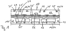
- Fig. 1 shows, purely schematically, a possible embodiment variant of the modular unit 10 according to the invention, which is designed with a sensor device 11 for actuating a movable part, in particular a flap of a motor vehicle.
- the module unit 10 has a carrier body 12 on which the sensor device 11 with at least one sensor 21 is arranged.
- the sensor 21 is fastened here to the carrier body 12 via fastening means 35.
- the sensor 21 here has an elongated configuration that extends transversely to the vehicle direction. Parallel to the schematically illustrated sensor 21, a further sensor 22 can be attached to the carrier body 12 at a distance, which is not explicitly illustrated.
- a third sensor 23 can also be fastened above the sensor 11 in the region of the fastening means 35, which are located on the upper edge region of the module unit 10.
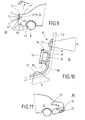
- the module unit 10 furthermore has an electrical unit 13 which is connected both to the sensor device 11 and to a main electrical unit 27 on the motor vehicle side, which is exemplarily shown in FIG Fig. 11 is shown, is connected.
- a checking module 26 is arranged on the module unit 10, which checks the functionality of the sensor device 11, in particular the individual sensors 11.
- the carrier body 12 is made of a plastic.
- the carrier body 12 and the module unit 10 are designed as individually manageable modules in such a way that the module unit 10 can be attached to the motor vehicle in a simple manner. This means that the module unit 10 with all in Fig. 1 illustrated components can be attached by the worker during assembly on a motor vehicle part.
- fastening elements 14 are shown purely schematically in the present exemplary embodiment, with which a fixation on the motor vehicle can be established. Furthermore, an emergency switch 28 is provided, which can be activated by the user using tactile means. If the functioning of the sensor device 11 should be disturbed, the user can actuate this emergency switch 28 in order to trigger a corresponding activation of the movable part 1.
- a motor vehicle 2 which has an emblem 15 on which, for example, the vehicle brand can be shown.
- the emblem 15 is integrated in the modular unit 10 according to the invention.
- the sensor device 11 has at least two sensors 21, 22.
- Fig. 3 is a possible sectional view in the area of the emblem 15 according to FIG Fig. 2 shown.
- the motor vehicle 2 has two fixing elements 36 on the inside, within which the module unit 10 is fixed.
- a first sensor 21 and a second sensor 22 are fastened in the carrier body 12.
- the emblem 15 is visibly attached to the outside.
- the carrier body 12 is designed as an independent component visible from the outside for the user, the carrier body 12 alone on its outer surface bearing the emblem 15, which is shown schematically in FIG Fig. 2 is indicated.
- the first sensor 21 has a first detection area 5 and the second sensor 22 has a second detection area 6.
- the detection areas 5, 6 can be of different sizes.
- the module unit 10 can be designed as a license plate lighting unit 9, which is shown in FIG Fig. 2 as in Fig. 7 is shown.
- the module unit 10 has two light units 29, 32 which are used to illuminate the license plate of the motor vehicle.
- the module unit 10 is designed with the electrical unit 13.
- the sensor device 11 is designed with a third sensor 23.
- the sensor 23 can work as a parking aid.
- the first sensor 21 and the second sensor 22 are also arranged on the module unit 10, the third sensor 23 being arranged centrally between the first sensor 21 and the second sensor 22.
- further positioning of the first sensor 21 and the second sensor 22 are conceivable.
- Fig. 2 Another exemplary embodiment is indicated, in which the module unit 10 can communicate with a third sensor 23 which is integrated on the motor vehicle side, in particular on a windshield wiper arrangement 16.
- Fig. 4 the carrier body 12 is shown, on which the first sensor 21 and the second sensor 22 are arranged. Furthermore, the carrier body 12 has four Positioning means 17 so that the fitter achieves an unambiguous fixation of the carrier body 12 on the motor vehicle component when fastening the module unit 10. These positioning means are designed as recesses. Alternative geometric embodiments and alternative positioning means are also conceivable.
- the module unit 10 is shown with the sensor device 11, the electrical unit 13 having a circuit board 18 on which the first sensor 21 and the second sensor 22 are arranged.
- a shielding element 37 is provided between the two sensors 21, 22. If the sensors 21, 22 are capacitive sensors, the shielding element 37 helps to ensure that the overall arrangement functions properly.
- the first detection area 5 is to be assigned to the first sensor 21 and the second detection area 6 to the second sensor 22.
- the electrical unit 13 is enclosed in a potting compound 19 which acts as a carrier body 12.
- the module unit 10 can, as in Fig. 1 already discussed, can be fixed on the motor vehicle via various fastening options.
- the module unit 10 has a first sensor 21 and a second sensor 22.
- a third sensor 23 can also be integrated in the module unit 10.
- the third sensor 23 has a third detection area 40.
- the tailgate 1 can be opened via a positive detection via the first 21 and the second sensor 22.
- a window 33 movably arranged on the flap 1 can be opened via a positive detection via the first 21 and the third sensor 23.
- the object only needs to approach first sensor 21 here.
- the movement of the pane 33 is then activated via a foot movement in the detection area 40.
- the flap 1 and / or the pane 33 can be closed again via a positive detection via the second sensor 22 and the third sensor 23.
- a motor vehicle 2 is indicated schematically, which is designed at its rear area with a modular unit 10 which has a first sensor 21 and a second sensor 22, which are each equipped with different detection areas 5, 6.
- the detection process can take place in such a way that both the first sensor 21 and the second sensor 22 simultaneously detect an object.
- the detection ranges of the detection areas are designed to be of different sizes.
- the detection area 5 has a small effective area, which means that the object must approach the module unit 10 very closely in order to be recognized by the sensor 5.
- the detection area 6 acts at a further distance than the first detection area 5.
- a detection can take place in such a way that an object 4 is initially detected via the second sensor 22. The object then has to come very close to the first sensor 21 so that a positive detection takes place in order to activate a corresponding actuation of the movable part 1. It is also conceivable that the first sensor 21 is used to detect the object 4 and then the second sensor 22 is activated in order to detect the object 4 within its second detection range.
- a further embodiment is shown purely schematically, in which the module unit 10 is arranged within a rear camera device 7 of a tailgate 1. Both sensors 21, 22 are integrated within the rear camera device 7.
- a third sensor 23 is located on the motor vehicle side on a bumper and has its detection area 40. The third sensor 23 can be addressed via a leg or foot movement of the user. Alternatively, it is also conceivable that the third sensor 23 is arranged inside the tire 8. The third sensor 23 within the tire 8 can be addressed by a targeted kick against the tire 8.
- the sensor 23 within the tire 8 can for example be a pressure sensor which detects such a tire impact.
- the camera of the rear camera device 7 can act as a first sensor 21 or a second sensor 22.
- Fig. 10 shows, purely schematically, a possible embodiment of the carrier body 12, on which a first sensor 21 and a second sensor 22 are arranged, their corresponding Have detection areas 5 and 6.
- the carrier body 12 has a corresponding profile 38 with a receptacle 24 in which the electrical unit 13 is arranged.
- a cover element 25 is placed on the profile 38, which is additionally designed with a seal 34.
- the electrical unit 13 can be completely cast inside the module carrier 10.
- the module carrier 10 is fastened to the motor vehicle 2 or to the movable part 1.
- the first sensor 21 is designed as a stiffening element.
- the first sensor 21 is located within the carrier body 12, a contact point 20 of the first sensor 21 protruding from the carrier body 12.
- the electrical unit 13 is placed on the contact point 20.
- the second sensor 22 is attached to the carrier body 12 at a distance from the first sensor 21.
- the second sensor 22 is connected to the electrical unit 13 via a cable element.
- the module unit 10 is attached to a motor vehicle part 1, 2.
- Fig. 13 shows a further embodiment of a modular unit 10, a sensor 21 being integrated as a partial sensor within the carrier body 12.
- the second sub-sensor 21 is placed on the inside of the support body 12. Both sub-sensors are electrically connected to one another, with both sub-sensors forming the first sensor 21 which, as in FIG Fig. 12 has an external contact point 20 to which the electrical unit 13 is connected.
- the electrical unit 13 is connected to the carrier body 12 via a screw connection.
- the second sensor 22 is also formed by two sub-sensors, the first sub-sensor being placed on the inside of the carrier body 12 and the second sub-sensor running inside the carrier body 12.
- the second sensor 22 also has a corresponding external contact point 20 which is connected to the electrical unit 13.
- the module unit 10 can be fastened to a motor vehicle part 1, 2.
- the module unit 10 has a corresponding profiling 38 implemented on the carrier body 12.
- a receptacle 24, within which the electrical unit 13 is arranged, is provided within the profiling 38 on the inside.
- the profile 38 is also arranged on the outside, with a receptacle 24 also being formed in the outer profile 38, within which the first sensor 21 is arranged.
- the outer profile 38 is designed with web-like extensions that lie directly on the motor vehicle part 2 and for reliable sealing and insulation of the first sensor 21 provide.
- the first sensor 21 is connected to the electrical unit 13.
- a second sensor 22 is integrated within the carrier body 12.
- the sensor 21 is also formed by the partial sensor 21 located inside the carrier body 12 and the partial sensor 21 located inside the outer profile 38. It is of course conceivable that only one sensor element 21 is arranged in the respective receptacle 24 of the external profile 38.
- the first sensor 21 is at least partially located between the carrier body 12 and the motor vehicle part 2.
- the sensor device 11 lies between the support body 12 and the motor vehicle part 1, 2 and that the support body 12 is positioned between the sensor device 11 and the motor vehicle part 1, 2.
- Fig. 16 shows a further alternative of a possible positioning of the module unit 10.
- the module unit 10 is located on the door sill of the sliding side door 42 of the motor vehicle 2.
- the sliding side door 42 can be moved according to the double arrow representation.
- the sliding side door 42 is in an open state.
- the module unit 10 can have an embodiment that is shown, for example, in the Figures 1 to 15 has been described. If the sliding door 42 is in the closed state, the sensor device of the module unit 10 can detect an authorized user in the vicinity of the sliding door 42, whereby a corresponding actuation or opening movement of the side sliding door 42 can be triggered.
- a third sensor 23 or at least one of the following third sensors can be arranged inside the motor vehicle 2, which are provided with the reference numerals 23.1, 23.2, 23.3, 23.4 and 23.5.
- the sensor 23.1 can be actuated via the user's foot.
- the sensor 23.2 can be actuated via the user's knee.
- the sensor 23.3 can be actuated via the elbow and / or the shoulder of the user.
- the sensor 23.4 can be actuated via the user's head.
- the sensor 23.5 can be actuated via the user's foot, knee or elbow. If the user is inside the motor vehicle 2, a closing movement of the sliding side door 42 can be triggered by actuating one of the third sensors 23 mentioned.
- the third sensors 23 are here with the electrical unit 13, in particular the control unit, so that both the sensors within the module unit 10 and the internal sensors 23 communicate with the same electrical unit.
- the user can trigger the opening movement of the sliding side door 42 by actuating an internal third sensor 23.
- authentication can take place in parallel, during which it is checked to what extent the user is actually the authorized user in order to implement such an opening movement. Authentication is usually carried out with an ID transmitter, which will be discussed below. It is also conceivable that no authentication takes place.
- the speed of the opening movement and / or the closing movement of the sliding door 42 can be variable.
- a speed setting is controlled or regulated via the electrical unit within the module unit 10.
- the electrical unit can be connected to a rain sensor.
- the control unit can, for example, provide a high speed for the opening movement and / or closing movement.
- Fig. 15 is shown purely schematically that the detection process 3, in which the sensor device 11 is active, an authentication process 31 can take place at the same time, in which it is checked to what extent the authorized person is allowed to trigger an actuation of the movable part. If the person carries a corresponding "correct" ID transmitter with them, positive authentication takes place.
- This authentication 31 can take place before the detection 3, during the detection 3 and after the detection 3.
- the detection here only includes the checking of a possible person or a possible object in the vicinity of the module unit 10, whereupon in the Figures 1 to 16 has been received in detail.
- step 39 the subsequent activation of the actuation of the movable part takes place, that is to say the opening process or the closing process of the movable part, but only if both a positive authentication 31 and a positive detection 3 are present.
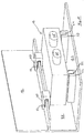
- the electrical unit 13 has a housing with two bar-shaped feet 51. With these two feet 51, the housing of the electrical unit 13 is supported on the support body 12, in particular a lower cross member 12.2 of the module unit 10.
- the feet 51 are in the present Fig. 17 however, not attached to the support body 12, so that additional holding elements 50 are used, which are also attached to the support body 12, in particular an upper cross member 12.1.
- the two holding elements 50 are arranged in the upper rear area on the left and right sides of the housing of the electrical unit 13. These holding elements 50 are, for example, materially connected to the housing in order to enable a mechanically secure hold.
- the holding elements 50 themselves interact with counter holding elements 50 'on the carrier 12, in particular a first cross member 12.1.
- a first cross member 12.1 conical or ramp-shaped projections can be provided, which interact positively with the counter-holding elements 50 ′ designed as bores on the first cross member 12.1.
- the electrical unit 13 is thus securely fastened to the carrier body 12 or the bumper or the door sill or the like, directly or indirectly, to the vehicle 2, even in the event of strong mechanical influences.
- the upper cross member 12.1 and the lower cross member 12.2 are also provided on the carrier body 12, which more or less form a U-shaped receptacle 24 for the electrical unit 13.
- the electrical unit 13 stands with its feet 51 on the lower cross member 12.2, although a hanging attachment to the first cross member 12.1 would also be conceivable.
- the feet 51 in the Figure 17 can themselves consist of an elastic material in order to absorb mechanical impacts. It is also conceivable that the electrical unit 13 is connected to the support body 12 or the vehicle 2 in a form-fitting and / or force-fitting and / or material fit only via the feet 51.
- the feet 51 are arranged in U-shaped buffers 52 in order to enable, on the one hand, a form-fitting attachment and, on the other hand, a shock-absorbing mounting of the electronic unit 13 on the vehicle 2 or carrier body 12.
- the U-shaped receptacle in the buffer elements 52 is designed to be open towards the front, wherein however, this can also be closed so that the electrical unit 13 is also attached to the carrier element 12 towards the front by the buffer elements 52.
- cylindrical feet 51 or the like are also used, which interact with corresponding buffer elements 52 of complementary design on the vehicle 2 or support body 12.
- the U-shaped holding elements 50 have basic metal clips 53 which claw into the upper cross member 12.1 of the carrier body 12 in order to hold the electrical unit 13 on the carrier body 12 in a form-fitting and / or force-fitting manner.
- two sensor connections 21 ', 22' are illustrated for the first sensor 21 and the second sensor 22.
- a third or further sensor can also be provided. Only one sensor 21 can also be present for the sensor device 11 or module unit 10 according to the invention.
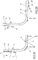
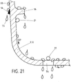
- a first water guide element 54 in the form of a wedge-shaped element is provided above the first sensor 21 on the outside of the support body 12 or on the bumper of the motor vehicle 2. If the water 55 (see arrow 57) runs along the outside, that is the side facing away from the sensors 21 and 22, it reaches the first water element 54 under the influence of gravity. The water flows due to the existing forces of adhesion 55 along the ramp-shaped water guide element 54 and detaches itself from the support body 12 or the bumper, door sill or the like at the lower tearing edge of the water guide element 54. The water 55 then drips from this tear-off edge onto the floor so that it is reliably prevented from flowing further along the outside and reaching the detection area 5 of the first sensor 21.
- Detection area 5 traverses, but not constantly, as in an exemplary flow movement, is located therein.
- another water guide element 54 which is approximately triangular in shape and also forms a tear-off edge for the water 55 flowing along it.
- the detection area 5 and 6 is purely schematic in FIG Figure 19 indicated for the two sensors 21 and 22.
- a further water guide element 54 is also arranged on the opposite side of the sensor element 22, which is designed in a manner comparable to the triangular water guide element described above. This right water guiding element 54 ensures that water 55 is also guided past the detection area 6 from the right side.
- the water guide elements 54 consist of a tear-off edge for the water 55.
- This water guide element 54 is also intended to ensure that the water 55 does not simply flow along the outer surface or possibly the inner surface of the support 12 or bumper, door sill or the like and into the detection area 5, 6 of the sensors 21, 22 arrives.
- the middle water guiding element 54 which is arranged on the left on the outer side of the second sensor 22, has a triangular or wedge-shaped incision in order to thus form a tear-off edge for the water 55.
- the arrow 57 shown represents the normal flow direction for the water 55.
- the additional arrow 56 indicates the wind direction when the vehicle 2 is moving, which also influences the flow direction of the water 55.
- the right water guide element 54 is also only shown as a tear-off edge for the sensor 22.
- inner water guide elements 54 are also provided for sensors 21, 22.
- a projection which serves as a water-guiding element 54, is provided above the first sensor 21.
- the lower edge of the projection-like water guide element 54 serves here as a tear-off edge for the water droplets 55 flowing along it.
- a triangular water guide element 54 is located on the outer side of the carrier body 12 intended.
- the two inner and outer water guide elements 54 for the first sensor 21 are arranged approximately at the same height on the carrier body 12. With this geometric arrangement, however, it is important that the water flowing away on the surface of the carrier body 12 is torn off in front of the detection area 5.
- a bore, opening or elongated hole or the like is provided in the carrier body 12 so that the water 55 that has accumulated within the carrier body 12 can escape.
- This water guide element 54 can also be arranged on the left and right of the second sensor 22 in order to prevent the water droplets 54 present in the detection area 6 of the second sensor 22 from flowing away.
- FIG. 22 For clarification is in the Figure 22 a three-dimensional view of two elongated water guide elements 54 under the sensor 22 is shown. As already mentioned, it is also expedient to arrange these slot-like water guide elements 54 on the left and right next to the corresponding sensor 21, 22, whereby fastening of the corresponding sensor 21, 22 is also facilitated.
- a bumper, a door sill, a side sill, a stone guard or the like can be used as a carrier for the sensors on the vehicle 2.
Landscapes
- Engineering & Computer Science (AREA)
- Mechanical Engineering (AREA)
- Computer Networks & Wireless Communication (AREA)
- Lock And Its Accessories (AREA)
- Power-Operated Mechanisms For Wings (AREA)
Claims (19)
- Unité modulaire (10) avec un dispositif de détection (11) pour l'actionnement d'une partie mobile (1, 33), en particulier d'un volet (1), d'un véhicule automobile (2), avec un corps de support (12) sur lequel est disposé le dispositif de détection (11) avec au moins un capteur optique (21, 22) pour permettre la détection (3) d'un utilisateur (4) essentiellement dans au moins une zone de détection (5, 6, 40) adjacente du véhicule automobile (2), de sorte que l'actionnement de la partie mobile (1, 33) peut être activé par la détection (3), caractérisée en ce que
l'unité modulaire (10) est conçue comme un module (10) gérable individuellement de telle sorte que l'unité modulaire (10) puisse être fixée sur le véhicule automobile (2), dans lequel l'unité modulaire (10) est conçue avec sa propre unité d'éclairage (32), qui communique à l'utilisateur (4) la distance nécessaire en fonction de son mode d'éclairage, et dans lequel l'unité d'éclairage (29) est conçue pour fournir un retour d'information à l'utilisateur via un mode d'éclairage défini, dans lequel le dispositif de détection (11) avec au moins un capteur (21, 22, 23) peut effectuer une mesure de référence afin de détecter d'abord les influences perturbatrices et, après que la mesure de référence a été effectuée, de mesurer une détection (3) de l'utilisateur (4) dans la zone de détection (5, 6, 40) par le capteur, et d'utiliser cette mesure de référence pour déterminer les valeurs seuils dans la mesure suivante,
dans lequel une unité électrique (13) reliée au dispositif de détection (11) est disposée sur le corps de support (12), et une valeur de mesure de référence provenant de la mesure de référence peut être enregistrée dans l'unité électrique (13) comme valeur de référence. - Unité modulaire (10) selon la revendication 1,
caractérisé en ce
qu'une unité électrique (13), notamment une unité de commande (13), reliée au dispositif de détection (11) est disposée sur le corps de support (12), et/ou en ce que le dispositif de détection (11) comporte au moins un premier (21) et un deuxième (22) capteurs, les capteurs (21, 22) présentant des zones de détection (5, 6) différentes, les différentes zones de détection (5, 6) étant notamment de tailles différentes. - Unité modulaire (10) selon la revendication 1 ou 2,
caractérisé en ce
que le capteur (21, 22, 23) comporte une extension allongée, le capteur (21, 22, 23) en particulier étant de conception flexible. - Unité de module (10) selon l'une des revendications précédentes,
caractérisé en ce
que le dispositif de détection (11) et/ou l'unité électrique (13) est fixé par complémentarité de forme, de force et/ou de matière sur le corps de support (12) et/ou est intégré dans le corps de support (12), en particulier le dispositif de détection (11) et/ou l'unité électrique (13) forment un composant monolithique avec le corps de support (12). - Unité de module (10) selon l'une des revendications précédentes,
caractérisé en ce
que l'unité électrique (13) est en communication de données avec au moins un autre, notamment un troisième, capteur (23) qui peut être disposé du côté du véhicule automobile, en particulier l'autre et/ou le troisième capteur (23) peuvent être disposés dans le pneu (8), sur le dispositif de caméra arrière (7), sur un éclairage de plaque d'immatriculation (9), sur une bande de garniture, sur un pare-chocs, sur un cylindre de serrure d'une unité de verrouillage, dans une unité de verrouillage pour bloquer la direction, dans un dispositif d'essuie-glace (16), dans un feu arrière, dans une poignée du véhicule automobile (2). - Unité modulaire (10) selon la revendication 5,
caractérisé en ce
qu'un autre, en particulier un troisième, capteur (23) est un capteur de chaleur, un capteur de distance, un capteur de parole, un capteur d'image, en particulier pour la reconnaissance du champ visuel. - Unité modulaire (10) selon l'une des revendications précédentes 2 à 6,
caractérisé en ce
que l'unité électrique (13) comporte une carte de circuit imprimé (18) sur laquelle sont disposés les capteurs (21, 22, 23), la carte de circuit imprimé (18) avec les capteurs (21, 22, 23) étant notamment intégrée dans une masse de coulée (19). - Unité modulaire (10) selon l'une des revendications précédentes 2 à 7,
caractérisé en ce
que le corps de support (12) comporte un réceptacle (24) dans lequel se trouve l'unité électrique (13), en particulier un élément de couvercle (25) fermant de manière étanche le réceptacle (24). - Unité modulaire (10) selon l'une des revendications précédentes 2 à 8,
caractérisé en ce
que l'unité électrique (13) transmet des signaux sans fil à une unité électrique principale (27) du côté du véhicule automobile, et/ou en ce que l'unité électrique (13) fait office d'unité électrique principale (27) du véhicule automobile (2). - Unité modulaire (10) selon l'une des revendications précédentes 2 à 9,
caractérisé en ce
que l'alimentation électrique de l'unité électrique (13) est inductive. - Unité de module (10) selon l'une des revendications précédentes,
caractérisé en ce
que l'unité d'éclairage (29) est activée pendant la détection (3). - Unité de module (10) selon l'une des revendications précédentes,
caractérisé en ce
qu'un contrôle de seuil est prévu qui détecte un contact réel de l'utilisateur avec la partie mobile (1, 33). - Unité de module (10) selon l'une des revendications précédentes,
caractérisé en ce
que l'unité modulaire (10) peut être disposée dans la zone arrière et/ou dans la zone de la porte latérale (41) du véhicule automobile (2), en particulier sous une porte latérale coulissante (42), l'unité électrique (13) étant en particulier reliée à au moins un troisième capteur (23) et/ou commutateur qui peut être disposé à l'intérieur du véhicule automobile (2), en particulier que le troisième capteur (23) et/ou commutateur peut être disposé dans le véhicule automobile (2) de telle sorte qu'il peut être actionné par le pied et/ou le genou et/ou le coude et/ou l'épaule et/ou la tête de l'utilisateur. - Unité modulaire (10) selon la revendication 13,
caractérisé en ce
qu'un mouvement d'ouverture et/ou de fermeture de la porte coulissante latérale (42) peut être déclenché par l'actionnement du troisième capteur (23) et/ou interrupteur, la vitesse du mouvement d'ouverture et/ou de fermeture de la porte coulissante (42) étant variable, en particulier l'unité électrique (13) qui commande et/ou régule la vitesse du mouvement d'ouverture et/ou de fermeture de la porte coulissante (42). - Procédé pour actionner une partie mobile (1, 33), en particulier un volet (1), d'un véhicule automobile (2), avec une unité modulaire (10) qui présente un corps de support (12) sur lequel est disposé un dispositif de détection (11) avec au moins un capteur optique (21, 22, 23), afin de permettre une détection (3) d'un utilisateur (4) essentiellement dans au moins une zone de détection (5, 6, 40) adjacente au véhicule automobile (2), de sorte que l'actionnement de la partie mobile (1, 33) puisse être activé par la détection (3), un processus d'authentification (31) étant prévu qui vérifie dans quelle mesure l'utilisateur (4) est autorisé à actionner la partie mobile (1, 33),
dans laquelle le processus d'authentification (31) a lieu avant la détection (3), après la détection (3) et/ou pendant la détection (3),
caractérisé en ce
que l'unité modulaire (10) est essentiellement fixée au véhicule automobile (2) en tant que module (10) pouvant être géré individuellement,
dans laquelle l'activation effective de la partie mobile (1, 33) est effectuée en fonction d'une distance définie que l'utilisateur (4) doit avoir par rapport à l'unité modulaire,
dans laquelle l'unité modulaire (10) est conçue avec sa propre unité d'éclairage (32) qui communique la distance nécessaire à l'utilisateur (4) en fonction de son mode d'éclairage,
et dans lequel l'unité d'éclairage (32) fournit un retour d'information à l'utilisateur (4) via un mode d'éclairage défini,
dans lequel le dispositif de détection (11) avec au moins un capteur (21, 22, 23) effectue d'abord une mesure de référence afin de détecter ainsi dans un premier temps des influences perturbatrices, dans lequel
le capteur (21, 22, 23), après que la mesure de référence a été effectuée, détecte métrologiquement une détection (3) de l'utilisateur (4) dans la zone de détection (5, 6, 40), dans laquelle
la mesure de référence est utilisée pour définir les valeurs seuils pour la mesure suivante,
dans lequel une unité électrique (13) reliée au dispositif de détection (11) est disposée sur le corps de support (12), et une valeur de mesure de référence provenant de la mesure de référence est mémorisée dans l'unité électrique (13) en tant que valeur de référence. - Procédé selon la revendication 15,
caractérisé en ce
que l'activation effective de la partie mobile (1, 33) a lieu après un temps défini que l'utilisateur (4) a à l'unité modulaire (10). - Procédé selon la revendication 16,
caractérisé en ce
que l'unité d'éclairage (32) communique la distance nécessaire à l'utilisateur (4) en fonction de son mode d'éclairage, afin que le mouvement d'ouverture de la partie mobile puisse avoir lieu sans mettre en danger l'utilisateur (4). - Procédé selon l'une des revendications précédentes 15 à 17,
caractérisé en ce
que l'actionnement de la partie mobile (1, 33) est activé en fonction d'un signal de vitesse du véhicule automobile. - Procédé selon l'une des revendications précédentes 15 à 18, avec laquelle une unité modulaire (10) est exploitable selon l'une des revendications 1 à 14.
Priority Applications (1)
| Application Number | Priority Date | Filing Date | Title |
|---|---|---|---|
| EP20195096.1A EP3778307B1 (fr) | 2009-07-17 | 2010-07-16 | Unité modulaire pourvue de capteur en boucle ou en u |
Applications Claiming Priority (7)
| Application Number | Priority Date | Filing Date | Title |
|---|---|---|---|
| DE102009033738 | 2009-07-17 | ||
| DE102009034549A DE102009034549A1 (de) | 2009-07-17 | 2009-07-23 | Moduleinheit |
| DE102010002560 | 2010-03-03 | ||
| DE102010002671 | 2010-03-08 | ||
| DE202010005427 | 2010-05-10 | ||
| EP10739535.2A EP2454435B1 (fr) | 2009-07-17 | 2010-07-16 | Unité modulaire avec dispositif détecteur |
| PCT/EP2010/060365 WO2011007008A2 (fr) | 2009-07-17 | 2010-07-16 | Dispositif détecteur et unité module correspondante |
Related Parent Applications (2)
| Application Number | Title | Priority Date | Filing Date |
|---|---|---|---|
| EP10739535.2A Division EP2454435B1 (fr) | 2009-07-17 | 2010-07-16 | Unité modulaire avec dispositif détecteur |
| EP10739535.2A Division-Into EP2454435B1 (fr) | 2009-07-17 | 2010-07-16 | Unité modulaire avec dispositif détecteur |
Related Child Applications (1)
| Application Number | Title | Priority Date | Filing Date |
|---|---|---|---|
| EP20195096.1A Division EP3778307B1 (fr) | 2009-07-17 | 2010-07-16 | Unité modulaire pourvue de capteur en boucle ou en u |
Publications (3)
| Publication Number | Publication Date |
|---|---|
| EP3141431A2 EP3141431A2 (fr) | 2017-03-15 |
| EP3141431A3 EP3141431A3 (fr) | 2017-07-26 |
| EP3141431B1 true EP3141431B1 (fr) | 2020-09-09 |
Family
ID=42937122
Family Applications (5)
| Application Number | Title | Priority Date | Filing Date |
|---|---|---|---|
| EP20195096.1A Active EP3778307B1 (fr) | 2009-07-17 | 2010-07-16 | Unité modulaire pourvue de capteur en boucle ou en u |
| EP10739535.2A Revoked EP2454435B1 (fr) | 2009-07-17 | 2010-07-16 | Unité modulaire avec dispositif détecteur |
| EP16178047.3A Active EP3141431B1 (fr) | 2009-07-17 | 2010-07-16 | Dispositif de capteur et son unité modulaire |
| EP16178045.7A Pending EP3130512A1 (fr) | 2009-07-17 | 2010-07-16 | Dispositif de capteur et son unite modulaire |
| EP16178044.0A Active EP3141685B2 (fr) | 2009-07-17 | 2010-07-16 | Dispositif de capteur et son unite modulaire |
Family Applications Before (2)
| Application Number | Title | Priority Date | Filing Date |
|---|---|---|---|
| EP20195096.1A Active EP3778307B1 (fr) | 2009-07-17 | 2010-07-16 | Unité modulaire pourvue de capteur en boucle ou en u |
| EP10739535.2A Revoked EP2454435B1 (fr) | 2009-07-17 | 2010-07-16 | Unité modulaire avec dispositif détecteur |
Family Applications After (2)
| Application Number | Title | Priority Date | Filing Date |
|---|---|---|---|
| EP16178045.7A Pending EP3130512A1 (fr) | 2009-07-17 | 2010-07-16 | Dispositif de capteur et son unite modulaire |
| EP16178044.0A Active EP3141685B2 (fr) | 2009-07-17 | 2010-07-16 | Dispositif de capteur et son unite modulaire |
Country Status (6)
| Country | Link |
|---|---|
| US (1) | US8874324B2 (fr) |
| EP (5) | EP3778307B1 (fr) |
| KR (1) | KR101743790B1 (fr) |
| CN (5) | CN102575495B (fr) |
| DE (8) | DE102010027508B4 (fr) |
| WO (1) | WO2011007008A2 (fr) |
Families Citing this family (89)
| Publication number | Priority date | Publication date | Assignee | Title |
|---|---|---|---|---|
| DE102009024062A1 (de) * | 2009-06-05 | 2010-12-09 | Valeo Schalter Und Sensoren Gmbh | Vorrichtung und Verfahren zur Anzeige von Objekten in einer Fahrzeugumgebung |
| DE102010027508B4 (de) * | 2009-07-17 | 2023-12-21 | Huf Hülsbeck & Fürst Gmbh & Co. Kg | Sensoreinrichtung sowie Moduleinheit dafür |
| US11634937B2 (en) | 2009-08-21 | 2023-04-25 | Uusi, Llc | Vehicle assembly having a capacitive sensor |
| US9705494B2 (en) * | 2009-08-21 | 2017-07-11 | Uusi, Llc | Vehicle assemblies having fascia panels with capacitance sensors operative for detecting proximal objects |
| US12320180B2 (en) | 2009-08-21 | 2025-06-03 | Uusi, Llc | Vehicle assembly having a capacitive sensor |
| US10017977B2 (en) | 2009-08-21 | 2018-07-10 | Uusi, Llc | Keyless entry assembly having capacitance sensor operative for detecting objects |
| US10954709B2 (en) | 2009-08-21 | 2021-03-23 | Uusi, Llc | Vehicle assembly having a capacitive sensor |
| US9051769B2 (en) | 2009-08-21 | 2015-06-09 | Uusi, Llc | Vehicle assembly having a capacitive sensor |
| US9845629B2 (en) | 2009-08-21 | 2017-12-19 | Uusi, Llc | Vehicle keyless entry assembly having capacitance sensor operative for detecting objects |
| DE102010034203B3 (de) * | 2010-08-12 | 2011-11-10 | Brose Fahrzeugteile Gmbh & Co. Kommanditgesellschaft, Hallstadt | Antriebsanordnung zur motorischen Verstellung einer Klappenanordnung |
| DE102010060364A1 (de) | 2010-11-04 | 2012-05-10 | Huf Hülsbeck & Fürst Gmbh & Co. Kg | Verfahren für ein Kraftfahrzeug |
| JP5643129B2 (ja) * | 2011-02-07 | 2014-12-17 | 株式会社アルファ | 車両の扉体制御装置 |
| KR20130026942A (ko) * | 2011-09-06 | 2013-03-14 | 한국전자통신연구원 | 차량의 위험감지장치 및 그 제어방법 |
| DE102011082547A1 (de) * | 2011-09-12 | 2013-03-14 | Brose Fahrzeugteile Gmbh & Co. Kommanditgesellschaft, Hallstadt | Vorrichtung zum Steuern und Überwachen von Funktionen eines Kraftfahrzeugs mit einem optischen Sensor |
| JP5924027B2 (ja) * | 2012-02-29 | 2016-05-25 | アイシン精機株式会社 | 車両用開閉体制御装置 |
| DE202012102047U1 (de) * | 2012-06-04 | 2013-09-06 | Brose Fahrzeugteile Gmbh & Co. Kommanditgesellschaft, Hallstadt | System mit Einklemmschutzvorrichtung für die Verstellung eines Schließelements an einem Fahrzeug |
| DE102012107116A1 (de) * | 2012-08-02 | 2014-02-06 | Brose Fahrzeugteile Gmbh & Co. Kommanditgesellschaft, Hallstadt | Verfahren zur Steuerung einer Verstellbewegung eines Fahrzeugschließelements mit Kollisionsvermeidung für einen Schlossbereich und Einklemmschutzsystem |
| DE102012107288A1 (de) * | 2012-08-08 | 2014-03-06 | Brose Fahrzeugteile Gmbh & Co. Kommanditgesellschaft, Hallstadt | Steuerungsverfahren und Steuerungssystem für ein Fahrzeugschließelement |
| US8626387B1 (en) * | 2012-11-14 | 2014-01-07 | Toyota Motor Engineering & Manufacturing North America, Inc. | Displaying information of interest based on occupant movement |
| CN105209706B (zh) | 2013-05-15 | 2018-11-02 | 麦格纳覆盖件有限公司 | 用于操作车辆的闭合板的方法和系统 |
| DE102013008725A1 (de) * | 2013-05-23 | 2014-12-11 | Brose Fahrzeugteile Gmbh & Co. Kommanditgesellschaft, Hallstadt | Einklemmschutz für eine Scheibe in einer Fahrzeugtür mit Schließhilfe |
| US9475369B2 (en) * | 2013-07-17 | 2016-10-25 | Aisin Seiki Kabushiki Kaisha | Vehicle door opening and closing apparatus and method of controlling the same |
| DE102013110866A1 (de) * | 2013-10-01 | 2015-04-02 | Brose Fahrzeugteile Gmbh & Co. Kommanditgesellschaft, Hallstadt | Kapazitive Sensoranordnung eines Kraftfahrzeugs |
| DE102013018838A1 (de) * | 2013-11-08 | 2015-05-13 | Brose Fahrzeugteile Gmbh & Co. Kommanditgesellschaft, Hallstadt | Fahrzeug mit einer Stellvorrichtung für eine Fahrzeugtür, Stellvorrichtung und Verwendung einer Stellvorrichtung |
| DE102014000408A1 (de) | 2013-11-27 | 2015-05-28 | Huf Hülsbeck & Fürst Gmbh & Co. Kg | Kraftfahrzeugsensoreinheit mit zumindest einem Sensor |
| DE102014101199A1 (de) * | 2014-01-31 | 2015-08-06 | Huf Hülsbeck & Fürst Gmbh & Co. Kg | Montagemodul für ein Kraftfahrzeug mit einem optischen Sensorsystem und einer Notbetätigung |
| DE102014101195A1 (de) * | 2014-01-31 | 2015-08-06 | Huf Hülsbeck & Fürst Gmbh & Co. Kg | Montagemodul für ein Kraftfahrzeug |
| DE102014107269A1 (de) * | 2014-05-22 | 2015-11-26 | Huf Hülsbeck & Fürst Gmbh & Co. Kg | Variabel einsetzbare Sensoreinheit |
| DE102014212780A1 (de) * | 2014-07-02 | 2016-01-07 | Robert Bosch Gmbh | Fahrzeugteil mit integriertem Sensor und Verfahren zu dessen Herstellung |
| DE102014010177B4 (de) * | 2014-07-09 | 2024-11-21 | Brose Fahrzeugteile Se & Co. Kommanditgesellschaft, Bamberg | Sensormodul zur berührungslosen Betätigung eines verstellbaren Fahrzeugteils |
| JP6211506B2 (ja) * | 2014-12-03 | 2017-10-11 | アイシン精機株式会社 | 車両用開閉体の開閉検知装置 |
| US9694735B2 (en) | 2015-01-26 | 2017-07-04 | Flextronics International Usa, Inc. | Vehicle emblem incorporating capacitive switch and LED lighting |
| JP6327194B2 (ja) * | 2015-04-23 | 2018-05-23 | トヨタ自動車株式会社 | レーダ装置 |
| US9470033B1 (en) | 2015-06-09 | 2016-10-18 | Ford Global Technologies, Llc | System and method for controlling vehicle access component |
| JP6333778B2 (ja) * | 2015-07-16 | 2018-05-30 | オムロンオートモーティブエレクトロニクス株式会社 | 車両用開閉体作動システム |
| DE102015214793A1 (de) * | 2015-08-03 | 2017-02-09 | Brose Fahrzeugteile Gmbh & Co. Kommanditgesellschaft, Bamberg | Bedienvorrichtung für eine motorisch verstellbare Seitentür eines Fahrzeugs |
| DE102015121405A1 (de) * | 2015-12-09 | 2017-06-14 | Huf Hülsbeck & Fürst GmbH & Co KG | Vorrichtung zur Positionsbestimmung |
| DE102016102667A1 (de) * | 2016-02-16 | 2017-08-17 | Brose Fahrzeugteile Gmbh & Co. Kommanditgesellschaft, Bamberg | Messelektrode für einen kapazitiven Näherungssensor eines Kraftfahrzeugs |
| US10087672B2 (en) * | 2016-02-22 | 2018-10-02 | GM Global Technology Operations LLC | Hands-free access control system for a closure of a vehicle |
| US10070286B2 (en) * | 2016-05-27 | 2018-09-04 | Analog Devices, Inc. | Single-wire sensor bus |
| CN106002917A (zh) * | 2016-06-13 | 2016-10-12 | 刘哲 | 一种电杆式自动化仓储机器人 |
| DE102016220032A1 (de) * | 2016-10-14 | 2018-04-19 | Robert Bosch Gmbh | Sensorvorrichtung für ein Fahrzeug, Kraftfahrzeug |
| DE102016220031A1 (de) * | 2016-10-14 | 2018-04-19 | Robert Bosch Gmbh | Sensorvorrichtung für ein Fahrzeug, Kraftfahrzeug |
| DE102016220036A1 (de) * | 2016-10-14 | 2018-04-19 | Robert Bosch Gmbh | Sensorvorrichtung für ein Fahrzeug, Kraftfahrzeug |
| US20180265043A1 (en) * | 2017-03-14 | 2018-09-20 | Ford Global Technologies, Llc | Proximity switch and humidity sensor assembly |
| US10480962B2 (en) | 2017-04-21 | 2019-11-19 | Capsule Technologies, Inc. | Electronic device including a capacitive sensor in a housing |
| US10023110B1 (en) * | 2017-04-21 | 2018-07-17 | Ford Global Technologies, Llc | Vehicle badge sensor assembly |
| US10914110B2 (en) * | 2017-11-02 | 2021-02-09 | Magna Closures Inc. | Multifunction radar based detection system for a vehicle liftgate |
| US11054514B2 (en) * | 2017-11-22 | 2021-07-06 | Magna Closures Inc. | Radar beam forming shield for motor vehicle |
| DE102017128774B4 (de) * | 2017-12-04 | 2023-11-02 | Witte Automotive Gmbh | Optisches Sensorsystem für ein Kraftfahrzeug |
| JP6923460B2 (ja) * | 2018-01-26 | 2021-08-18 | トヨタ自動車株式会社 | 車両下部構造 |
| JP7093648B2 (ja) * | 2018-02-27 | 2022-06-30 | 株式会社ホンダアクセス | 超音波センサの取付構造 |
| DE102018107184A1 (de) | 2018-03-26 | 2019-09-26 | Brose Fahrzeugteile Gmbh & Co. Kommanditgesellschaft, Bamberg | Verfahren zur Ansteuerung einer motorischen Klappenanordnung eines Kraftfahrzeugs |
| TWI708695B (zh) * | 2018-07-06 | 2020-11-01 | 為升電裝工業股份有限公司 | 車用雷達裝置 |
| CN109057616A (zh) * | 2018-08-31 | 2018-12-21 | 佛山市顺德区美的洗涤电器制造有限公司 | 家用电器及其门控制系统和方法 |
| DE102018222197B3 (de) * | 2018-12-18 | 2020-06-18 | Witte Automotive Gmbh | Vorrichtung sowie ein Verfahren zur Erkennung von mindestens einem Objekt in einem Umgebungsbereich eines Fahrzeugs |
| JP7256441B2 (ja) * | 2019-01-15 | 2023-04-12 | 株式会社豊田自動織機 | ブラケットの取付構造 |
| DE102019102879A1 (de) * | 2019-02-06 | 2020-08-06 | HELLA GmbH & Co. KGaA | Baueinheit zur Anordnung im Frontend oder im Heckend eines Kraftfahrzeugs |
| EP3678112B1 (fr) * | 2019-02-21 | 2024-12-04 | LG Electronics Inc. | Procédé et dispositif d'enregistrement d'emplacement de parking |
| DE102019108467A1 (de) * | 2019-04-01 | 2020-10-01 | Brose Fahrzeugteile Se & Co. Kommanditgesellschaft, Bamberg | Steuersystem für eine elektrische Antriebsanordnung einer Klappe eines Kraftfahrzeugs |
| DE102019210912A1 (de) * | 2019-07-23 | 2021-01-28 | Brose Fahrzeugteile Se & Co. Kommanditgesellschaft, Bamberg | Verstellvorrichtung und Verfahren für die fremdkraftbetätigte Verstellung eines Verstellteils an einem Fahrzeug auf Basis wenigstens eines Bedienereignisses |
| DE102019121280A1 (de) * | 2019-08-07 | 2021-02-11 | Kiekert Aktiengesellschaft | Verfahren und vorrichtung zum aufstellen eines kraftfahrzeugtürelements |
| DE102019122206B4 (de) * | 2019-08-19 | 2021-07-08 | Webasto SE | Dachmodul zur Bildung eines Fahrzeugdachs mit Umfeldsensor |
| DE102020121603A1 (de) * | 2019-09-05 | 2021-03-11 | Huf Hülsbeck & Fürst Gmbh & Co. Kg | Betätigungsvorrichtung mit bewegbarem Schaltelement, Fahrzeug sowie Betätigungsverfahren |
| DE102019123876A1 (de) * | 2019-09-05 | 2021-03-11 | Brose Fahrzeugteile Se & Co. Kommanditgesellschaft, Bamberg | System und Verfahren zum Verstellen einer Fahrzeugtür relativ zu einer Fahrzeugkarosserie |
| DE102019123871A1 (de) | 2019-09-05 | 2021-03-11 | Brose Fahrzeugteile Se & Co. Kommanditgesellschaft, Bamberg | System und Verfahren zum Verstellen einer Fahrzeugtür relativ zu einer Fahrzeugkarosserie |
| CN210478550U (zh) * | 2019-09-17 | 2020-05-08 | 延锋彼欧汽车外饰系统有限公司 | 一种吸收震动偏差的柔性雷达支架 |
| DE102019219240A1 (de) * | 2019-12-10 | 2021-06-10 | Psa Automobiles Sa | Kraftfahrzeugassistenzsystem, Verfahren zum berührungslosen Öffnen einer Klappe, Haube oder Tür eines Kraftfahrzeugs, Computerprogrammprodukt, sowie Kraftfahrzeug |
| DE102020102887A1 (de) * | 2020-02-05 | 2021-08-05 | Huf Hülsbeck & Fürst Gmbh & Co. Kg | Betätigungsvorrichtung mit Verkleidungselement, Fahrzeug, sowie Verfahren |
| DE102020102897A1 (de) * | 2020-02-05 | 2021-08-05 | Huf Hülsbeck & Fürst Gmbh & Co. Kg | Modulare Betätigungsvorrichtung, Fahrzeug, sowie Verfahren |
| JP7267229B2 (ja) * | 2020-04-08 | 2023-05-01 | ミネベアアクセスソリューションズ株式会社 | 動作検出装置 |
| DE102020112797A1 (de) | 2020-05-12 | 2021-11-18 | Bayerische Motoren Werke Aktiengesellschaft | Bedieneinheit für eine Fahrzeugtür |
| JP7556705B2 (ja) * | 2020-06-18 | 2024-09-26 | トヨタ自動車九州株式会社 | キックセンサの構造及びその取付け構造 |
| KR20220023091A (ko) * | 2020-08-20 | 2022-03-02 | 현대자동차주식회사 | 차량 및 그 제어방법 |
| WO2022054389A1 (fr) * | 2020-09-11 | 2022-03-17 | 三菱自動車工業株式会社 | Structure de montage de capteur de pare-chocs de véhicule |
| DE102020216512A1 (de) | 2020-12-22 | 2022-06-23 | Witte Automotive Gmbh | Multi-Sensormodul, ein Griffmodul und bewegliches Fahrzeugelement |
| JP7538060B2 (ja) * | 2021-02-19 | 2024-08-21 | トヨタ自動車株式会社 | 車両のキックセンサ取付構造 |
| DE102021203384B3 (de) * | 2021-04-06 | 2022-06-23 | Vitesco Technologies GmbH | Fahrzeug mit Sensoreinheit zur berührungslosen Betätigung eines Fahrzeugelements |
| DE102021119150A1 (de) | 2021-07-23 | 2023-01-26 | Infineon Technologies Ag | Sensorsystem |
| DE102021209108A1 (de) | 2021-08-19 | 2023-02-23 | Vitesco Technologies GmbH | Vorrichtung und Verfahren zum Schließen einer Fahrzeugklappe eines Fahrzeugs |
| DE102021126043A1 (de) | 2021-10-07 | 2023-04-13 | Minebea Mitsumi Inc. | Sensorvorrichtung eines türgriffs für ein kraftfahrzeug |
| DE102021130337B3 (de) | 2021-11-19 | 2023-02-02 | Webasto SE | Sensormodul zur Anbringung an einem Flächenbauteil eines Kraftfahrzeuges und Flächenbauteil mit einem derartigen Sensormodul |
| EP4209649A1 (fr) * | 2021-12-30 | 2023-07-12 | Witte Automotive GmbH | Élément décoratif comprenant un module d'actionnement, élément de véhicule et véhicule |
| US20230243200A1 (en) * | 2022-01-31 | 2023-08-03 | Panasonic Automotive Systems Company Of America, Division Of Panasonic Corporation Of North America | Vehicle door safety system |
| DE102022003183B4 (de) | 2022-08-31 | 2026-07-02 | Jost-Werke Deutschland Gmbh | Kupplungsvorrichtung für ein Zugfahrzeug mit einem daran angebrachten Objekterkennungsmittel |
| USD1073985S1 (en) | 2022-10-18 | 2025-05-06 | Uusi, Llc | Sensor weather seal |
| DE102022128826A1 (de) * | 2022-10-31 | 2024-05-02 | Brose Fahrzeugteile Se & Co. Kommanditgesellschaft, Bamberg | Radaranordnung für eine motorische Klappenanordnung eines Kraftfahrzeugs |
| IT202200024675A1 (it) * | 2022-11-30 | 2024-05-30 | Seri Plast S R L | Sistema con frontalino intelligente e metodo di produzione |
| US12605991B2 (en) * | 2023-12-18 | 2026-04-21 | Honda Motor Co., Ltd. | Vehicle door including sensor attachment scheme |
Family Cites Families (63)
| Publication number | Priority date | Publication date | Assignee | Title |
|---|---|---|---|---|
| FR2740501B1 (fr) * | 1995-10-26 | 1998-06-19 | Valeo Securite Habitacle | Systeme mains libres de deverrouillage et/ou d'ouverture d'ouvrant de vehicule automobile |
| DE19610621C1 (de) | 1996-03-19 | 1997-10-02 | Webasto Karosseriesysteme | Einrichtung zum niederschlagsabhängigen Schließen eines öffnungsfähigen Fahrzeugteils |
| DE19636821A1 (de) † | 1996-09-11 | 1998-03-12 | Teves Gmbh Alfred | Verfahren zur Prüfung elektrischer Bauteile und Vorrichtung zur Durchführung des Verfahrens |
| US5923027A (en) * | 1997-09-16 | 1999-07-13 | Gentex Corporation | Moisture sensor and windshield fog detector using an image sensor |
| FR2771534B1 (fr) † | 1997-11-24 | 2000-06-09 | Valeo Systemes De Fermetures | Vehicule automobile equipe d'un systeme de detection de l'approche d'un utilisateur |
| JPH11235961A (ja) † | 1998-02-20 | 1999-08-31 | Aisin Seiki Co Ltd | 車両の物体検出装置 |
| DE19829731A1 (de) * | 1998-07-03 | 2000-01-05 | Mannesmann Vdo Ag | Kraftfahrzeug mit Heckklappe |
| CN1288321C (zh) * | 1999-05-13 | 2006-12-06 | 松下电器产业株式会社 | 压敏传感器及对象检测装置 |
| JP4552169B2 (ja) | 1999-11-09 | 2010-09-29 | マツダ株式会社 | 車両の開閉体制御装置 |
| US6337549B1 (en) † | 2000-05-12 | 2002-01-08 | Anthony Gerald Bledin | Capacitive anti finger trap proximity sensor |
| DE50201932D1 (de) † | 2001-02-21 | 2005-02-10 | Kiekert Ag | Schlüssellose Betätigungs und/oder Schliesseinrichtung |
| DE60228639D1 (de) | 2001-04-12 | 2008-10-09 | Automotive Electronics Ltd Ab | Kapazitiver Sensor |
| GB2376075A (en) † | 2001-06-01 | 2002-12-04 | Ab Automotive Electronics Ltd | Bumper proximity detector using capacitive sensor |
| FR2833032B1 (fr) † | 2001-12-03 | 2004-11-26 | Valeo Securite Habitacle | Systeme de fermeture de coffre motorisee pour vehicule automobile |
| JP4003453B2 (ja) * | 2001-12-26 | 2007-11-07 | アイシン精機株式会社 | 人体検出装置 |
| DE10205281B4 (de) | 2002-02-05 | 2009-12-31 | Iris-Gmbh Infrared & Intelligent Sensors | System zur Türraumüberwachung eines Fahrzeugs |
| DE10215591B4 (de) † | 2002-02-20 | 2019-05-23 | Huf Hülsbeck & Fürst Gmbh & Co. Kg | Auslösesignalgeber |
| ATE350730T1 (de) † | 2002-02-20 | 2007-01-15 | Kiekert Ag | Kraftfahrzeug mit auslösesignalgeber |
| US20030216817A1 (en) * | 2002-05-16 | 2003-11-20 | Richard Pudney | Vehicle access system with sensor |
| DE10232413A1 (de) | 2002-07-17 | 2004-02-19 | Webasto Vehicle Systems International Gmbh | Verfahren und Vorrichtung zum Verstellen eines bewegbaren Fahrzeugteils |
| DE20214892U1 (de) | 2002-09-25 | 2002-11-21 | Donnelly Hohe GmbH & Co. KG, 97903 Collenberg | Überwachungseinrichtung für ein Kraftfahrzeug |
| FR2845051B1 (fr) * | 2002-09-26 | 2005-06-03 | Arvinmeritor Light Vehicle Sys | Vehicule a detection optique multi-fonctions |
| JP4196172B2 (ja) * | 2003-01-10 | 2008-12-17 | オムロン株式会社 | 検知装置及び錠制御装置 |
| DE10310066B3 (de) † | 2003-03-07 | 2005-02-17 | Metzeler Automotive Profile Systems Gmbh | Vorrichtung zum Erkennen eines Hindernisses in dem Öffnungsbereich eines bewegbaren Schließelements |
| JP4348993B2 (ja) † | 2003-04-24 | 2009-10-21 | アイシン精機株式会社 | 電気部品及びその製造方法 |
| DE10340263B4 (de) † | 2003-08-29 | 2014-12-18 | Magna Electronics Europe Gmbh & Co.Kg | Vorbaustruktur für ein Kraftfahrzeug |
| DE10340592B4 (de) | 2003-09-01 | 2005-06-30 | Cts Fahrzeug-Dachsysteme Gmbh | Kollisionsschutzeinrichtung für ein verstellbares Deckelement in einem Fahrzeug |
| JP4098215B2 (ja) * | 2003-10-29 | 2008-06-11 | アイシン精機株式会社 | 車両用人体検出装置 |
| CA2550588C (fr) † | 2003-12-18 | 2012-01-03 | Intier Automotive Closures Inc. | Capteur capacitif differentiel anti-pincement |
| DE102004002164A1 (de) * | 2004-01-15 | 2005-08-04 | Robert Bosch Gmbh | Strahlungsdetektor, Sensormodul mit einem Strahlungsdetektor und Verfahren zum Herstellen eines Strahlungsdetektors |
| EP1582670B1 (fr) * | 2004-03-30 | 2010-06-16 | Kabushiki Kaisha Honda Lock | Dispositif de poignée pour porte de véhicule |
| JP4310695B2 (ja) † | 2004-03-30 | 2009-08-12 | アイシン精機株式会社 | 静電容量変化検出装置 |
| FR2870801B1 (fr) † | 2004-05-28 | 2007-09-14 | Plastic Omnium Cie | Absorbeur de pare-chocs de vehicule automobile |
| JP4788114B2 (ja) † | 2004-06-29 | 2011-10-05 | アイシン精機株式会社 | 開閉体の制御装置 |
| DE102004033760A1 (de) | 2004-07-13 | 2006-02-02 | Daimlerchrysler Ag | Kraftfahrzeug mit einer Sensorvorrichtung |
| DE102004041709C5 (de) * | 2004-08-28 | 2009-11-12 | Bayerische Motoren Werke Aktiengesellschaft | Fahrzeug mit automatisch öffnender Klappe |
| DE102004054134B4 (de) † | 2004-11-08 | 2019-08-22 | Huf Hülsbeck & Fürst Gmbh & Co. Kg | Verfahren zur Steuerung eines Schließsystems eines Kraftfahrzeugs |
| DE102004064181B4 (de) † | 2004-11-08 | 2019-05-09 | Huf Hülsbeck & Fürst Gmbh & Co. Kg | Verfahren zur Steuerung eines Schließsystems eines Kraftfahrzeugs |
| DE102005034097B4 (de) | 2005-02-04 | 2025-07-10 | Volkswagen Ag | Schließsystem für ein Fahrzeug |
| DE102005029411A1 (de) | 2005-06-24 | 2007-01-04 | Audi Ag | Vorrichtung und Verfahren zum Betreiben einer Sensoranordnung in einem Kraftfahrzeug |
| DE102005032402B3 (de) * | 2005-07-12 | 2006-09-28 | Daimlerchrysler Ag | Verfahren zum Nachweis einer Berechtigung zum Ver- oder Entriegeln eines Objekts sowie Sicherheitsvorrichtung |
| DE602005004156T2 (de) * | 2005-10-21 | 2008-12-18 | C.R.F. Società Consortile per Azioni, Orbassano | Optischer Multifunktionssensor für Fahrassistenzsysteme in Kraftfahrzeugen |
| DE102005055087A1 (de) * | 2005-11-18 | 2007-05-24 | Robert Bosch Gmbh | Scheinwerfermodul mit integriertem Licht-Regensensor |
| US7688179B2 (en) * | 2005-12-12 | 2010-03-30 | Denso International America, Inc. | Hands-free vehicle door opener |
| DE202005020140U1 (de) † | 2005-12-22 | 2007-05-10 | BROSE SCHLIEßSYSTEME GMBH & CO. KG | Kraftfahrzeugtüranordnung |
| DE102006001719A1 (de) | 2006-01-13 | 2007-08-02 | Ford Global Technologies, LLC, Dearborn | Vorrichtung zur Ansteuerung einer Fahrzeugtürverriegelung |
| DE202006000866U1 (de) | 2006-01-20 | 2007-05-24 | Brose Fahrzeugteile Gmbh & Co. Kommanditgesellschaft, Coburg | Verstellsystem für ein Kraftfahrzeug sowie taktiler Sensor |
| CN101117872A (zh) * | 2006-03-13 | 2008-02-06 | Dt工程株式会社 | 带关门器的门用延迟装置、带延迟装置的关门器以及带具备延迟装置的关门器的门 |
| FR2899629A1 (fr) * | 2006-04-11 | 2007-10-12 | Renault Sas | Agencement d'ouvrant a mains libres pour un vehicule automobile |
| DE102006044112A1 (de) * | 2006-09-20 | 2008-03-27 | Hella Kgaa Hueck & Co. | Kraftfahrzeug mit einer Sensoranordnung |
| DE102006062772B4 (de) | 2006-10-31 | 2012-03-01 | Webasto Ag | Verfahren zum Bereitstellen eines Einklemmschutzes für bewegte Teile eines Kraftfahrzeugs, insbesondere zur Verwirklichung eines Einklemmschutzes bei einem Cabriolet-Fahrzeug |
| FR2917771B1 (fr) * | 2007-06-25 | 2009-09-04 | Valeo Securite Habitacle Sas | Procede securise de fermeture automatique d'un hayon de vehicule automobile |
| JP4946684B2 (ja) * | 2007-07-13 | 2012-06-06 | トヨタ自動車株式会社 | 移動体 |
| FR2920172B1 (fr) * | 2007-08-21 | 2009-12-04 | Valeo Securite Habitacle | Procede de deverrouillage automatique d'un ouvrant de vehicule automobile pour systeme mains-libre et dispositif pour la mise en oeuvre du procede |
| US7500711B1 (en) * | 2007-08-24 | 2009-03-10 | Ford Global Technologies, Llc | Power door for a passenger vehicle |
| DE102007041288A1 (de) * | 2007-08-31 | 2009-03-05 | GM Global Technology Operations, Inc., Detroit | Kraftfahrzeug mit einem schlüssellosen Zugangssystem |
| US8098037B2 (en) * | 2007-11-08 | 2012-01-17 | Aisin Seiki Kabushiki Kaisha | Vehicle door opening-closing apparatus |
| DE102008012287A1 (de) | 2008-03-03 | 2009-09-10 | Continental Automotive Gmbh | Vorrichtung und Zugangskontrollsystem sowie Verfahren zur Auswertung von biometrischen Daten |
| EP2098671B1 (fr) † | 2008-03-04 | 2013-07-31 | Hella KGaA Hueck & Co. | Véhicule automobile doté d'une pièce de véhicule réglable automatiquement en position ouverte ou fermée |
| DE202009018206U1 (de) † | 2008-04-29 | 2011-05-05 | Volkswagen Ag | Vorrichtung zur Betätigung einer Tür oder Klappe eines Fahrzeugs |
| DE102008021989A1 (de) † | 2008-05-02 | 2008-12-18 | Daimler Ag | Vorrichtung zum Ver- und Entriegeln einer mittels eines elektronischen Zugangsberechtigungssystems gesicherten Fahrzeugtür für ein Fahrzeug |
| DE102010027508B4 (de) * | 2009-07-17 | 2023-12-21 | Huf Hülsbeck & Fürst Gmbh & Co. Kg | Sensoreinrichtung sowie Moduleinheit dafür |
| DE102009059202A1 (de) * | 2009-07-20 | 2011-02-03 | Huf Hülsbeck & Fürst Gmbh & Co. Kg | Sensormodul |
-
2010
- 2010-07-16 DE DE102010027508.5A patent/DE102010027508B4/de active Active
- 2010-07-16 DE DE102010027504.2A patent/DE102010027504B4/de active Active
- 2010-07-16 US US13/383,624 patent/US8874324B2/en active Active
- 2010-07-16 EP EP20195096.1A patent/EP3778307B1/fr active Active
- 2010-07-16 CN CN201080032442.4A patent/CN102575495B/zh active Active
- 2010-07-16 DE DE102010027505.0A patent/DE102010027505B4/de active Active
- 2010-07-16 EP EP10739535.2A patent/EP2454435B1/fr not_active Revoked
- 2010-07-16 EP EP16178047.3A patent/EP3141431B1/fr active Active
- 2010-07-16 CN CN201510061052.4A patent/CN104675269B/zh active Active
- 2010-07-16 KR KR1020127003620A patent/KR101743790B1/ko active Active
- 2010-07-16 CN CN201510062153.3A patent/CN104691442B/zh active Active
- 2010-07-16 DE DE102010027509.3A patent/DE102010027509B4/de active Active
- 2010-07-16 EP EP16178045.7A patent/EP3130512A1/fr active Pending
- 2010-07-16 DE DE102010027507.7A patent/DE102010027507B4/de active Active
- 2010-07-16 CN CN201510060992.1A patent/CN104675268B/zh active Active
- 2010-07-16 DE DE102010027503.4A patent/DE102010027503B4/de active Active
- 2010-07-16 CN CN201510062328.0A patent/CN104675270B/zh active Active
- 2010-07-16 DE DE102010027502.6A patent/DE102010027502B4/de active Active
- 2010-07-16 EP EP16178044.0A patent/EP3141685B2/fr active Active
- 2010-07-16 WO PCT/EP2010/060365 patent/WO2011007008A2/fr not_active Ceased
- 2010-07-16 DE DE102010027506.9A patent/DE102010027506B4/de active Active
Non-Patent Citations (1)
| Title |
|---|
| None * |
Also Published As
Similar Documents
| Publication | Publication Date | Title |
|---|---|---|
| EP3141685B1 (fr) | Unite modulaire avec dispositif de capteur | |
| EP2824002B1 (fr) | Procédé destiné à ouvrir ou fermer un véhicule automobile | |
| EP1789645B1 (fr) | Vehicule a trappe a ouverture automatique | |
| EP2531384B1 (fr) | Commutateur virtuel et procédé pour le faire fonctionner | |
| DE102013010993A1 (de) | Objekterfassungsvorrichtung für ein Fahrzeug | |
| WO2009132766A1 (fr) | Procédé et dispositif d’actionnement d’une porte ou d’une trappe de véhicule | |
| DE102008041354A1 (de) | Verfahren und Vorrichtung zum automatischen Öffnen einer Fahrzeugtüre oder dergleichen | |
| DE102014110091A1 (de) | Griffvorrichtung zum Betätigen einer Schließvorrichtung | |
| WO2009049749A2 (fr) | Système de détection multifonction permettant de détecter des précipitations ainsi que l'environnement de véhicules | |
| DE102015214793A1 (de) | Bedienvorrichtung für eine motorisch verstellbare Seitentür eines Fahrzeugs | |
| EP1659542A1 (fr) | Système de fermeture pour un véhicule | |
| DE102009034549A1 (de) | Moduleinheit | |
| DE102006036934B4 (de) | Vorrichtung mit einer Fahrzeugsensorik |
Legal Events
| Date | Code | Title | Description |
|---|---|---|---|
| PUAI | Public reference made under article 153(3) epc to a published international application that has entered the european phase |
Free format text: ORIGINAL CODE: 0009012 |
|
| STAA | Information on the status of an ep patent application or granted ep patent |
Free format text: STATUS: THE APPLICATION HAS BEEN PUBLISHED |
|
| AC | Divisional application: reference to earlier application |
Ref document number: 2454435 Country of ref document: EP Kind code of ref document: P |
|
| AK | Designated contracting states |
Kind code of ref document: A2 Designated state(s): AL AT BE BG CH CY CZ DE DK EE ES FI FR GB GR HR HU IE IS IT LI LT LU LV MC MK MT NL NO PL PT RO SE SI SK SM TR |
|
| PUAL | Search report despatched |
Free format text: ORIGINAL CODE: 0009013 |
|
| AK | Designated contracting states |
Kind code of ref document: A3 Designated state(s): AL AT BE BG CH CY CZ DE DK EE ES FI FR GB GR HR HU IE IS IT LI LT LU LV MC MK MT NL NO PL PT RO SE SI SK SM TR |
|
| RIC1 | Information provided on ipc code assigned before grant |
Ipc: B60R 13/07 20060101AFI20170616BHEP Ipc: E05F 15/76 20150101ALI20170616BHEP Ipc: E05F 15/77 20150101ALI20170616BHEP Ipc: E05F 15/73 20150101ALI20170616BHEP |
|
| STAA | Information on the status of an ep patent application or granted ep patent |
Free format text: STATUS: REQUEST FOR EXAMINATION WAS MADE |
|
| 17P | Request for examination filed |
Effective date: 20180126 |
|
| RBV | Designated contracting states (corrected) |
Designated state(s): AL AT BE BG CH CY CZ DE DK EE ES FI FR GB GR HR HU IE IS IT LI LT LU LV MC MK MT NL NO PL PT RO SE SI SK SM TR |
|
| STAA | Information on the status of an ep patent application or granted ep patent |
Free format text: STATUS: EXAMINATION IS IN PROGRESS |
|
| 17Q | First examination report despatched |
Effective date: 20180323 |
|
| GRAP | Despatch of communication of intention to grant a patent |
Free format text: ORIGINAL CODE: EPIDOSNIGR1 |
|
| STAA | Information on the status of an ep patent application or granted ep patent |
Free format text: STATUS: GRANT OF PATENT IS INTENDED |
|
| INTG | Intention to grant announced |
Effective date: 20200226 |
|
| GRAS | Grant fee paid |
Free format text: ORIGINAL CODE: EPIDOSNIGR3 |
|
| GRAA | (expected) grant |
Free format text: ORIGINAL CODE: 0009210 |
|
| STAA | Information on the status of an ep patent application or granted ep patent |
Free format text: STATUS: THE PATENT HAS BEEN GRANTED |
|
| AC | Divisional application: reference to earlier application |
Ref document number: 2454435 Country of ref document: EP Kind code of ref document: P |
|
| AK | Designated contracting states |
Kind code of ref document: B1 Designated state(s): AL AT BE BG CH CY CZ DE DK EE ES FI FR GB GR HR HU IE IS IT LI LT LU LV MC MK MT NL NO PL PT RO SE SI SK SM TR |
|
| REG | Reference to a national code |
Ref country code: GB Ref legal event code: FG4D Free format text: NOT ENGLISH |
|
| REG | Reference to a national code |
Ref country code: AT Ref legal event code: REF Ref document number: 1311202 Country of ref document: AT Kind code of ref document: T Effective date: 20200915 Ref country code: CH Ref legal event code: EP |
|
| REG | Reference to a national code |
Ref country code: IE Ref legal event code: FG4D Free format text: LANGUAGE OF EP DOCUMENT: GERMAN |
|
| REG | Reference to a national code |
Ref country code: DE Ref legal event code: R096 Ref document number: 502010016749 Country of ref document: DE |
|
| REG | Reference to a national code |
Ref country code: LT Ref legal event code: MG4D |
|
| PG25 | Lapsed in a contracting state [announced via postgrant information from national office to epo] |
Ref country code: GR Free format text: LAPSE BECAUSE OF FAILURE TO SUBMIT A TRANSLATION OF THE DESCRIPTION OR TO PAY THE FEE WITHIN THE PRESCRIBED TIME-LIMIT Effective date: 20201210 Ref country code: LT Free format text: LAPSE BECAUSE OF FAILURE TO SUBMIT A TRANSLATION OF THE DESCRIPTION OR TO PAY THE FEE WITHIN THE PRESCRIBED TIME-LIMIT Effective date: 20200909 Ref country code: FI Free format text: LAPSE BECAUSE OF FAILURE TO SUBMIT A TRANSLATION OF THE DESCRIPTION OR TO PAY THE FEE WITHIN THE PRESCRIBED TIME-LIMIT Effective date: 20200909 Ref country code: BG Free format text: LAPSE BECAUSE OF FAILURE TO SUBMIT A TRANSLATION OF THE DESCRIPTION OR TO PAY THE FEE WITHIN THE PRESCRIBED TIME-LIMIT Effective date: 20201209 Ref country code: NO Free format text: LAPSE BECAUSE OF FAILURE TO SUBMIT A TRANSLATION OF THE DESCRIPTION OR TO PAY THE FEE WITHIN THE PRESCRIBED TIME-LIMIT Effective date: 20201209 Ref country code: SE Free format text: LAPSE BECAUSE OF FAILURE TO SUBMIT A TRANSLATION OF THE DESCRIPTION OR TO PAY THE FEE WITHIN THE PRESCRIBED TIME-LIMIT Effective date: 20200909 Ref country code: HR Free format text: LAPSE BECAUSE OF FAILURE TO SUBMIT A TRANSLATION OF THE DESCRIPTION OR TO PAY THE FEE WITHIN THE PRESCRIBED TIME-LIMIT Effective date: 20200909 |
|
| REG | Reference to a national code |
Ref country code: NL Ref legal event code: MP Effective date: 20200909 |
|
| PG25 | Lapsed in a contracting state [announced via postgrant information from national office to epo] |
Ref country code: PL Free format text: LAPSE BECAUSE OF FAILURE TO SUBMIT A TRANSLATION OF THE DESCRIPTION OR TO PAY THE FEE WITHIN THE PRESCRIBED TIME-LIMIT Effective date: 20200909 Ref country code: LV Free format text: LAPSE BECAUSE OF FAILURE TO SUBMIT A TRANSLATION OF THE DESCRIPTION OR TO PAY THE FEE WITHIN THE PRESCRIBED TIME-LIMIT Effective date: 20200909 |
|
| PG25 | Lapsed in a contracting state [announced via postgrant information from national office to epo] |
Ref country code: PT Free format text: LAPSE BECAUSE OF FAILURE TO SUBMIT A TRANSLATION OF THE DESCRIPTION OR TO PAY THE FEE WITHIN THE PRESCRIBED TIME-LIMIT Effective date: 20210111 Ref country code: SM Free format text: LAPSE BECAUSE OF FAILURE TO SUBMIT A TRANSLATION OF THE DESCRIPTION OR TO PAY THE FEE WITHIN THE PRESCRIBED TIME-LIMIT Effective date: 20200909 Ref country code: RO Free format text: LAPSE BECAUSE OF FAILURE TO SUBMIT A TRANSLATION OF THE DESCRIPTION OR TO PAY THE FEE WITHIN THE PRESCRIBED TIME-LIMIT Effective date: 20200909 Ref country code: CZ Free format text: LAPSE BECAUSE OF FAILURE TO SUBMIT A TRANSLATION OF THE DESCRIPTION OR TO PAY THE FEE WITHIN THE PRESCRIBED TIME-LIMIT Effective date: 20200909 Ref country code: NL Free format text: LAPSE BECAUSE OF FAILURE TO SUBMIT A TRANSLATION OF THE DESCRIPTION OR TO PAY THE FEE WITHIN THE PRESCRIBED TIME-LIMIT Effective date: 20200909 Ref country code: EE Free format text: LAPSE BECAUSE OF FAILURE TO SUBMIT A TRANSLATION OF THE DESCRIPTION OR TO PAY THE FEE WITHIN THE PRESCRIBED TIME-LIMIT Effective date: 20200909 |
|
| PG25 | Lapsed in a contracting state [announced via postgrant information from national office to epo] |
Ref country code: AL Free format text: LAPSE BECAUSE OF FAILURE TO SUBMIT A TRANSLATION OF THE DESCRIPTION OR TO PAY THE FEE WITHIN THE PRESCRIBED TIME-LIMIT Effective date: 20200909 Ref country code: ES Free format text: LAPSE BECAUSE OF FAILURE TO SUBMIT A TRANSLATION OF THE DESCRIPTION OR TO PAY THE FEE WITHIN THE PRESCRIBED TIME-LIMIT Effective date: 20200909 Ref country code: IS Free format text: LAPSE BECAUSE OF FAILURE TO SUBMIT A TRANSLATION OF THE DESCRIPTION OR TO PAY THE FEE WITHIN THE PRESCRIBED TIME-LIMIT Effective date: 20210109 |
|
| REG | Reference to a national code |
Ref country code: DE Ref legal event code: R097 Ref document number: 502010016749 Country of ref document: DE |
|
| PG25 | Lapsed in a contracting state [announced via postgrant information from national office to epo] |
Ref country code: SK Free format text: LAPSE BECAUSE OF FAILURE TO SUBMIT A TRANSLATION OF THE DESCRIPTION OR TO PAY THE FEE WITHIN THE PRESCRIBED TIME-LIMIT Effective date: 20200909 |
|
| PLBE | No opposition filed within time limit |
Free format text: ORIGINAL CODE: 0009261 |
|
| STAA | Information on the status of an ep patent application or granted ep patent |
Free format text: STATUS: NO OPPOSITION FILED WITHIN TIME LIMIT |
|
| 26N | No opposition filed |
Effective date: 20210610 |
|
| PG25 | Lapsed in a contracting state [announced via postgrant information from national office to epo] |
Ref country code: DK Free format text: LAPSE BECAUSE OF FAILURE TO SUBMIT A TRANSLATION OF THE DESCRIPTION OR TO PAY THE FEE WITHIN THE PRESCRIBED TIME-LIMIT Effective date: 20200909 Ref country code: SI Free format text: LAPSE BECAUSE OF FAILURE TO SUBMIT A TRANSLATION OF THE DESCRIPTION OR TO PAY THE FEE WITHIN THE PRESCRIBED TIME-LIMIT Effective date: 20200909 |
|
| PG25 | Lapsed in a contracting state [announced via postgrant information from national office to epo] |
Ref country code: IT Free format text: LAPSE BECAUSE OF FAILURE TO SUBMIT A TRANSLATION OF THE DESCRIPTION OR TO PAY THE FEE WITHIN THE PRESCRIBED TIME-LIMIT Effective date: 20200909 |
|
| REG | Reference to a national code |
Ref country code: CH Ref legal event code: PL |
|
| PG25 | Lapsed in a contracting state [announced via postgrant information from national office to epo] |
Ref country code: MC Free format text: LAPSE BECAUSE OF FAILURE TO SUBMIT A TRANSLATION OF THE DESCRIPTION OR TO PAY THE FEE WITHIN THE PRESCRIBED TIME-LIMIT Effective date: 20200909 |
|
| REG | Reference to a national code |
Ref country code: BE Ref legal event code: MM Effective date: 20210731 |
|
| PG25 | Lapsed in a contracting state [announced via postgrant information from national office to epo] |
Ref country code: LI Free format text: LAPSE BECAUSE OF NON-PAYMENT OF DUE FEES Effective date: 20210731 Ref country code: CH Free format text: LAPSE BECAUSE OF NON-PAYMENT OF DUE FEES Effective date: 20210731 |
|
| PG25 | Lapsed in a contracting state [announced via postgrant information from national office to epo] |
Ref country code: LU Free format text: LAPSE BECAUSE OF NON-PAYMENT OF DUE FEES Effective date: 20210716 |
|
| PG25 | Lapsed in a contracting state [announced via postgrant information from national office to epo] |
Ref country code: IE Free format text: LAPSE BECAUSE OF NON-PAYMENT OF DUE FEES Effective date: 20210716 Ref country code: BE Free format text: LAPSE BECAUSE OF NON-PAYMENT OF DUE FEES Effective date: 20210731 |
|
| REG | Reference to a national code |
Ref country code: AT Ref legal event code: MM01 Ref document number: 1311202 Country of ref document: AT Kind code of ref document: T Effective date: 20210716 |
|
| REG | Reference to a national code |
Ref country code: DE Ref legal event code: R082 Ref document number: 502010016749 Country of ref document: DE Representative=s name: BALS & VOGEL PATENTANWAELTE PARTG MBB, DE |
|
| PG25 | Lapsed in a contracting state [announced via postgrant information from national office to epo] |
Ref country code: AT Free format text: LAPSE BECAUSE OF NON-PAYMENT OF DUE FEES Effective date: 20210716 |
|
| PG25 | Lapsed in a contracting state [announced via postgrant information from national office to epo] |
Ref country code: HU Free format text: LAPSE BECAUSE OF FAILURE TO SUBMIT A TRANSLATION OF THE DESCRIPTION OR TO PAY THE FEE WITHIN THE PRESCRIBED TIME-LIMIT; INVALID AB INITIO Effective date: 20100716 Ref country code: CY Free format text: LAPSE BECAUSE OF FAILURE TO SUBMIT A TRANSLATION OF THE DESCRIPTION OR TO PAY THE FEE WITHIN THE PRESCRIBED TIME-LIMIT Effective date: 20200909 |
|
| P01 | Opt-out of the competence of the unified patent court (upc) registered |
Effective date: 20230425 |
|
| PG25 | Lapsed in a contracting state [announced via postgrant information from national office to epo] |
Ref country code: MK Free format text: LAPSE BECAUSE OF FAILURE TO SUBMIT A TRANSLATION OF THE DESCRIPTION OR TO PAY THE FEE WITHIN THE PRESCRIBED TIME-LIMIT Effective date: 20200909 |
|
| PG25 | Lapsed in a contracting state [announced via postgrant information from national office to epo] |
Ref country code: MT Free format text: LAPSE BECAUSE OF FAILURE TO SUBMIT A TRANSLATION OF THE DESCRIPTION OR TO PAY THE FEE WITHIN THE PRESCRIBED TIME-LIMIT Effective date: 20200909 |
|
| PGFP | Annual fee paid to national office [announced via postgrant information from national office to epo] |
Ref country code: DE Payment date: 20250731 Year of fee payment: 16 |
|
| PGFP | Annual fee paid to national office [announced via postgrant information from national office to epo] |
Ref country code: GB Payment date: 20250724 Year of fee payment: 16 |
|
| PGFP | Annual fee paid to national office [announced via postgrant information from national office to epo] |
Ref country code: FR Payment date: 20250723 Year of fee payment: 16 |
|
| PG25 | Lapsed in a contracting state [announced via postgrant information from national office to epo] |
Ref country code: TR Free format text: LAPSE BECAUSE OF FAILURE TO SUBMIT A TRANSLATION OF THE DESCRIPTION OR TO PAY THE FEE WITHIN THE PRESCRIBED TIME-LIMIT Effective date: 20200909 |
|
| REG | Reference to a national code |
Ref country code: DE Ref legal event code: R084 Ref document number: 502010016749 Country of ref document: DE |