EP3141470A1 - Vorrichtung zum vertäuen eines boots an einer anlegestelle eines bootsanlegers, und entsprechender bootsanleger - Google Patents
Vorrichtung zum vertäuen eines boots an einer anlegestelle eines bootsanlegers, und entsprechender bootsanleger Download PDFInfo
- Publication number
- EP3141470A1 EP3141470A1 EP16185782.6A EP16185782A EP3141470A1 EP 3141470 A1 EP3141470 A1 EP 3141470A1 EP 16185782 A EP16185782 A EP 16185782A EP 3141470 A1 EP3141470 A1 EP 3141470A1
- Authority
- EP
- European Patent Office
- Prior art keywords
- ship
- mooring
- mooring device
- pontoon
- bars
- Prior art date
- Legal status (The legal status is an assumption and is not a legal conclusion. Google has not performed a legal analysis and makes no representation as to the accuracy of the status listed.)
- Withdrawn
Links
- 238000003032 molecular docking Methods 0.000 claims abstract description 42
- 238000003780 insertion Methods 0.000 claims abstract description 4
- 230000037431 insertion Effects 0.000 claims abstract description 4
- 238000013519 translation Methods 0.000 claims description 8
- 238000006073 displacement reaction Methods 0.000 description 9
- XLYOFNOQVPJJNP-UHFFFAOYSA-N water Substances O XLYOFNOQVPJJNP-UHFFFAOYSA-N 0.000 description 7
- 238000004519 manufacturing process Methods 0.000 description 2
- 238000011144 upstream manufacturing Methods 0.000 description 2
- 238000013459 approach Methods 0.000 description 1
- 230000007423 decrease Effects 0.000 description 1
- 238000013461 design Methods 0.000 description 1
- 238000001514 detection method Methods 0.000 description 1
- 238000009434 installation Methods 0.000 description 1
- 238000012423 maintenance Methods 0.000 description 1
- 230000007257 malfunction Effects 0.000 description 1
- 238000000034 method Methods 0.000 description 1
- 230000010355 oscillation Effects 0.000 description 1
- 230000000717 retained effect Effects 0.000 description 1
- 230000001960 triggered effect Effects 0.000 description 1
Images





Classifications
-
- B—PERFORMING OPERATIONS; TRANSPORTING
- B63—SHIPS OR OTHER WATERBORNE VESSELS; RELATED EQUIPMENT
- B63B—SHIPS OR OTHER WATERBORNE VESSELS; EQUIPMENT FOR SHIPPING
- B63B21/00—Tying-up; Shifting, towing, or pushing equipment; Anchoring
-
- C—CHEMISTRY; METALLURGY
- C07—ORGANIC CHEMISTRY
- C07K—PEPTIDES
- C07K5/00—Peptides containing up to four amino acids in a fully defined sequence; Derivatives thereof
- C07K5/04—Peptides containing up to four amino acids in a fully defined sequence; Derivatives thereof containing only normal peptide links
- C07K5/08—Tripeptides
- C07K5/0802—Tripeptides with the first amino acid being neutral
- C07K5/0812—Tripeptides with the first amino acid being neutral and aromatic or cycloaliphatic
-
- A—HUMAN NECESSITIES
- A61—MEDICAL OR VETERINARY SCIENCE; HYGIENE
- A61K—PREPARATIONS FOR MEDICAL, DENTAL OR TOILETRY PURPOSES
- A61K38/00—Medicinal preparations containing peptides
- A61K38/04—Peptides having up to 20 amino acids in a fully defined sequence; Derivatives thereof
- A61K38/12—Cyclic peptides, e.g. bacitracins; Polymyxins; Gramicidins S, C; Tyrocidins A, B or C
-
- A—HUMAN NECESSITIES
- A61—MEDICAL OR VETERINARY SCIENCE; HYGIENE
- A61K—PREPARATIONS FOR MEDICAL, DENTAL OR TOILETRY PURPOSES
- A61K8/00—Cosmetics or similar toiletry preparations
- A61K8/18—Cosmetics or similar toiletry preparations characterised by the composition
- A61K8/30—Cosmetics or similar toiletry preparations characterised by the composition containing organic compounds
- A61K8/64—Proteins; Peptides; Derivatives or degradation products thereof
-
- A—HUMAN NECESSITIES
- A61—MEDICAL OR VETERINARY SCIENCE; HYGIENE
- A61K—PREPARATIONS FOR MEDICAL, DENTAL OR TOILETRY PURPOSES
- A61K9/00—Medicinal preparations characterised by special physical form
- A61K9/0012—Galenical forms characterised by the site of application
- A61K9/0014—Skin, i.e. galenical aspects of topical compositions
-
- A—HUMAN NECESSITIES
- A61—MEDICAL OR VETERINARY SCIENCE; HYGIENE
- A61K—PREPARATIONS FOR MEDICAL, DENTAL OR TOILETRY PURPOSES
- A61K9/00—Medicinal preparations characterised by special physical form
- A61K9/0012—Galenical forms characterised by the site of application
- A61K9/0048—Eye, e.g. artificial tears
-
- A—HUMAN NECESSITIES
- A61—MEDICAL OR VETERINARY SCIENCE; HYGIENE
- A61P—SPECIFIC THERAPEUTIC ACTIVITY OF CHEMICAL COMPOUNDS OR MEDICINAL PREPARATIONS
- A61P15/00—Drugs for genital or sexual disorders; Contraceptives
- A61P15/08—Drugs for genital or sexual disorders; Contraceptives for gonadal disorders or for enhancing fertility, e.g. inducers of ovulation or of spermatogenesis
-
- C—CHEMISTRY; METALLURGY
- C07—ORGANIC CHEMISTRY
- C07K—PEPTIDES
- C07K14/00—Peptides having more than 20 amino acids; Gastrins; Somatostatins; Melanotropins; Derivatives thereof
- C07K14/435—Peptides having more than 20 amino acids; Gastrins; Somatostatins; Melanotropins; Derivatives thereof from animals; from humans
- C07K14/705—Receptors; Cell surface antigens; Cell surface determinants
-
- C—CHEMISTRY; METALLURGY
- C07—ORGANIC CHEMISTRY
- C07K—PEPTIDES
- C07K7/00—Peptides having 5 to 20 amino acids in a fully defined sequence; Derivatives thereof
- C07K7/64—Cyclic peptides containing only normal peptide links
-
- E—FIXED CONSTRUCTIONS
- E02—HYDRAULIC ENGINEERING; FOUNDATIONS; SOIL SHIFTING
- E02B—HYDRAULIC ENGINEERING
- E02B3/00—Engineering works in connection with control or use of streams, rivers, coasts, or other marine sites; Sealings or joints for engineering works in general
- E02B3/20—Equipment for shipping on coasts, in harbours or on other fixed marine structures, e.g. bollards
- E02B3/24—Mooring posts
-
- B—PERFORMING OPERATIONS; TRANSPORTING
- B63—SHIPS OR OTHER WATERBORNE VESSELS; RELATED EQUIPMENT
- B63B—SHIPS OR OTHER WATERBORNE VESSELS; EQUIPMENT FOR SHIPPING
- B63B21/00—Tying-up; Shifting, towing, or pushing equipment; Anchoring
- B63B2021/003—Mooring or anchoring equipment, not otherwise provided for
-
- B—PERFORMING OPERATIONS; TRANSPORTING
- B63—SHIPS OR OTHER WATERBORNE VESSELS; RELATED EQUIPMENT
- B63B—SHIPS OR OTHER WATERBORNE VESSELS; EQUIPMENT FOR SHIPPING
- B63B21/00—Tying-up; Shifting, towing, or pushing equipment; Anchoring
- B63B2021/003—Mooring or anchoring equipment, not otherwise provided for
- B63B2021/004—Quick release elements in mooring connections
-
- B—PERFORMING OPERATIONS; TRANSPORTING
- B63—SHIPS OR OTHER WATERBORNE VESSELS; RELATED EQUIPMENT
- B63B—SHIPS OR OTHER WATERBORNE VESSELS; EQUIPMENT FOR SHIPPING
- B63B21/00—Tying-up; Shifting, towing, or pushing equipment; Anchoring
- B63B21/04—Fastening or guiding equipment for chains, ropes, hawsers, or the like
- B63B21/08—Clamping devices
-
- B—PERFORMING OPERATIONS; TRANSPORTING
- B63—SHIPS OR OTHER WATERBORNE VESSELS; RELATED EQUIPMENT
- B63B—SHIPS OR OTHER WATERBORNE VESSELS; EQUIPMENT FOR SHIPPING
- B63B21/00—Tying-up; Shifting, towing, or pushing equipment; Anchoring
- B63B21/50—Anchoring arrangements or methods for special vessels, e.g. for floating drilling platforms or dredgers
Definitions
- the invention relates to a device for docking a ship at a berth of a pontoon or a dock, for example.
- the invention also relates to a pontoon equipped with one or more mooring devices.
- the present invention may especially be implemented at sea, lake or river, and is particularly, but not exclusively, suitable for recreational craft.
- Mooring a vessel for example a pleasure boat or a sailboat, is the last phase of a docking maneuver. It consists in keeping the ship against a pontoon, for example, and connecting it to the latter in order to limit the movements of the ship with respect to the pontoon.
- a known technique illustrated on the figure 1 , consists in connecting the ship (not shown) to a pontoon C by the implementation of a rope B and one or more mooring points A may take the form of a cleat, a bitte or a ring. The number of mooring points depends on the size of the vessel.
- a disadvantage of this approach is that it requires the presence of one or more people.
- the ship being subject to the movements of water (swell), such a mooring maneuver presents risks for those present.
- a mooring is not very secure and there is a relatively high risk of stealing the ship.
- the patent application WO2009 / 073897 proposes the implementation of a locking mechanism which comprises a vertical bar secured to a pontoon, and arranged between the bow guide elements of a boat having a general V shape.
- a carabiner located on the bow of the boat is intended to grab the vertical bar so as to reversibly moor the ship to the pontoon.
- the pontoon has a hinge that allows the locking mechanism to follow the movements of the water (due to the tide and / or swell).
- the invention in at least one embodiment, has the particular objective of overcoming at least some disadvantages of the state of the art.
- an objective is to facilitate the docking of a boat at a docking station of a dock or pontoon, particularly for a user (a boater in particular) who would be alone on board.
- Another objective of at least one embodiment of the invention is to provide a docking device which is simple in design (and thus inexpensive), reliable, robust, secure and which eliminates, or at least minimizes the risks for the user.
- Yet another object of at least one embodiment of the invention is to provide such a mooring device which can adapt to the movements of the water and the variable sizes of the vessels.
- said gripping bars are movable relative to one another between a locking position (closed), in which the gripping bars are brought together and holding said engagement means, and a position unlocking device (open), wherein the attachment bars are spaced apart allowing the withdrawal (or release) or insertion of said engagement means.
- mobile attachment bars facilitates the docking and release of a ship at a docking station located on a pontoon, for example.
- the tie bars are interconnected by at least one pivot connection allowing movement of the jaws relative to each other.
- the engagement means for example carried by the ship, can be placed between the open grip bars, and once closed, be held by the tie bars, allowing easy and reliable docking of the ship to the pontoon .
- the opening of the tie-bars allows the withdrawal of the engagement means and the distance of the ship from the pontoon.
- the attachment bars which are for example integral with the pontoon, extend in a plane perpendicular to the pontoon surface and are, for example, interconnected at least at one of their ends. Preferably, they are interconnected at each of their ends so as to ensure a reliable docking of the ship.
- tie bars are fixed on the ship while the engagement means are integral with the pontoon.
- tie bars offer a degree of freedom to the engagement means arranged and retained between the tie-bars and makes it possible to reduce the forces applied to the mooring device in case of rough sea, by example.
- the attachment bars allow the engagement means to move vertically between them so as to follow the movements of the water (due to the tide and / or swell).
- the space between the tie bars also allows lateral play of the engagement means.
- attachment bars are adapted to receive a variety of engagement means height, this height depending on the type of boat.
- Such a mooring device has a structure and operation that are simple, and facilitates the docking maneuver and docking of a ship to a pontoon (and conversely, the undocking of the ship).
- the mooring of the ship is also secure.
- such a mooring device can be easily adapted to an existing pontoon and any type of ship.
- said engagement means comprise a first end portion connected by a central portion of reduced width / section to a second end portion, the latter end being connected to the ship or the post of mooring.
- the engagement means comprise a first end portion wider than the central portion.
- it may be a "T” shaped element, the horizontal bar of the "T” being the first end portion and the vertical bar of the "T", the central portion of reduced width.
- said second end portion has a light intended to cooperate with a mooring pole or away from the ship.
- the second end portion of the engagement means connected to the ship for example, has a light for cooperating with a pole handled by a boater located on the pontoon so as to place the engagement means between the tie bars during docking, or to push (or away) the engagement means away from the tie bars when starting the ship.
- a boom can be automatic.
- the latter are located on either side of said central portion.
- said first end portion is disposed on a first side of the tie bars, the gap between the tie bars in the locking position being less than the width of said first portion end.
- the distance between the tie bars in the locking position is greater than the width of said central portion.
- the distance between the tie bars in the locking position is less than the width of said second end portion.
- the distance between them is less than the width of the first and second end portions of the engagement means.
- the tie bars are locked between the first and second end portions of the engaging means.
- the gap between the tie bars is greater than the width of the central portion and thus allows a vertical displacement, that is to say along an axis parallel to the axis of the bars. hooking, engagement means between the tie bars.
- This configuration therefore allows the ship to move vertically according to the movements of the water (swell, tide) and thus to limit the stresses / mechanical forces applied to the device.
- the engagement means comprise a first fixed part integral with the ship or the berth, and a second part removably mounted on the first fixed part and intended to cooperate with the means of locking.
- Such a removable part makes it possible to manually insert the first end portion of the engagement means between the attachment bars of the locking means without having to move the bars between the open (unlocked) position. and the closed (locked) position.
- Such engagement means are compatible with a device which has mobile hanging bars (in this case, it is not necessary to detach the removable part) but also with a device whose attachment bars would be fixed.
- the engagement means comprise a first fixed part integral with the ship or berth, and a second part pivotally mounted on the first fixed part and intended to cooperate with the means. locking.
- pivoting part makes it possible to insert the first end portion of the engagement means between the bars of the locking means without having to move the bars between the open / unlocked position and the closed / locked position. . It is only necessary to rotate 90 ° (vertical position) this pivoting part in order to pass the first end portion of the engagement means beyond the tie bars, then to pivot the pivoting part again from 90 ° (horizontal position) to block the engagement means between the tie bars and thus allow secure docking of the ship.
- Such engagement means are also compatible with a device which would have movable grip bars or fixed tie bars.
- each attachment bar carries at at least one of its ends a pivotally mounted bracket with a corresponding bracket of the other tie bar, the tie bars and the brackets thus forming two movable jaws.
- brackets at one or each end of the tie bars makes it possible to form two jaws which make it possible to ensure a secure mooring of a ship at a berth, in a simple and inexpensive way.
- said locking means comprise actuating means acting on at least one square of each jaw.
- said actuating means comprise a pair of rods pivotally mounted about the same axis at a first end thereof, each of said rods being pivotally mounted at a second end on a separate bracket. one of said jaws.
- said rods are pivotally mounted at their first end on support means movable in translation so as to vary the opening angle between the two rods.
- the support means are connected to an actuating cam by a rod.
- said cam is moved by a motor.
- the opening and closing of the jaws are automatic and facilitate the mooring maneuver.
- said cam is moved by a handle connected to said cam by an axis.
- the opening and closing of the jaws can be done manually.
- the device further comprises means for centering and guiding the engagement means to the locking means, located on either side of the tie bars.
- centering and guiding means make it possible to simplify the engagement of the engagement means in the locking means so as to facilitate the docking maneuver.
- These guide means are useful for a boater who would be alone on board or during difficult weather conditions, in particular.
- said locking means are movable relative to said mooring station when they are carried by the latter.
- said locking means are carried by at least one carriage adapted to move in translation on a rail, said rail being fixedly mounted on the mooring station.
- the docking device comprises means for moving the locking means on the berth, a pontoon for example.
- Such means allow increased flexibility of the device.
- the docking device of the invention can be adapted to any type of installation intended to accommodate ships at sea, river, or lake, in particular.
- the invention also relates to a pontoon comprising one or more mooring devices as described above.
- the mooring device of the invention comprises, in the embodiments described below, locking means, in the form of two spaced tie rods which are integral with a port facility (a pontoon, for example ), and commitment means which are integral with a ship (a pleasure boat, for example) to moor at the port facility and which are intended to come between the tie bars.
- the bars allow the engagement means to move vertically between them so as to follow the movements of the water (due to the tide and / or swell).
- the first and second embodiments described below show an identical operating principle in which the locking means carried by the pontoon comprise two jaws movable relative to each other in order to grip the engagement means carried. by a ship.
- the third and fourth embodiments describe a different operating principle of the first two embodiments since the two jaws are fixed and it is the engagement means carried by a ship that must be moved and / or manipulated in order to cooperate with the jaws of the pontoon.
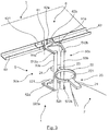
- a docking device 1 of a ship 2 is partially represented on the perspective views of figures 2 and 3 .
- This docking device 1 is implemented in a marina, for example.
- locking means 5 comprising two grip jaws 50a and 50b, integral with a floating pontoon 3, and engagement means 20 integral with a ship 2, which is moored to the pontoon 3 on the figure 3 .
- the locking means 5 are secured to the pontoon 3 by means of a profile 63, extending longitudinally along the pontoon 3.
- the profile 63 can receive a plurality of locking means, so as to to accommodate a plurality of vessels.
- the profile 63 which is secured to the upper surface of the pontoon 3, here has a substantially U-shaped section. Obviously, a section of different shape could be implemented.
- the docking device 1 further comprises actuating means 6 locking means 5 comprising an actuator (not shown), which can be controlled manually or automatically.
- the actuator acts on a movable portion 631 of the profile 63 thus allowing the movable portion 631 of the profile 63 to move perpendicularly to the longitudinal axis of the profile 63, in the same plane.
- the movable portion 631 carries a fixed support element 61 on which are articulated around a same axis of rotation 621 two levers, or rods, 62a and 62b, which extend, forming a V variable angle, in direction of the ship 2 to moor.
- the rods 62a and 62b are respectively integral at one end of an upper bracket 51a and 51b. These brackets 51a, 51b are movably mounted in rotation on the levers 62a and 62b respectively about an axis 513a, 513b located in the vicinity of their corner / right angle.
- the upper brackets 51a and 51b are connected to each other via a pivot connection, or axis of rotation, 511 located at a first of their ends.
- the locking means 5 further comprises a pair of lower brackets 52a and 52b which are connected between one another via a pivot connection, or axis of rotation 521 located at a first end thereof.
- brackets 51a, 51b, 52a, 52b are interconnected by a pair of tie bars 53a, 53b extending in a plane perpendicular to the plane of the brackets, levers 62a and 62b, and the profile 63 (and pontoon 3).
- first tie bar 53a is fixed between the respective ends 512a, 522a of the brackets 51a, 52a.
- second tie bar 53b is fixed between the respective ends 512b and 522b (not visible) of the brackets 51b and 52b.
- the lower brackets 52a, 52b are not secured to the pontoon 3.
- these brackets 52a, 52b are secured to the pontoon in a manner similar to the upper brackets 51a and 51b.
- the assembly consisting of bars 53a, 53b and brackets 51a, 51b, 52a, 52b, thus forms two jaws 50a, 50b movable between an open position ( figure 2 ) and a closed position ( figure 3 ).
- These jaws 50a, 50b can move between an open position (as shown in FIG. figure 2 ) in which the hook bars 53a, 53b are spaced apart from one another allowing insertion or withdrawal of the engagement means 20 (each pair of brackets substantially forming a "W"), and a position closed (as illustrated on the figure 3 ), wherein the tie bars 53a, 53b are brought together and maintain the engagement means 20 carried by the ship 2 (each pair of brackets forming substantially a "U").
- the locking means 5 comprising the jaws 50a, 50b are therefore intended to cooperate with the engagement means 20 integral with the front tip of the ship 2.
- These engaging means 20 comprise an axle 21 which is attached to the ship (by screwing, for example) and which is extended by a ring-shaped member 22 having an inner lumen 221.
- a boater located on the pontoon can thus introduce a gaff or a pole in the ring 22 so as to pull and guide the ship 2 to the locking means 5, or to push the ship 2 away from the pontoon 3.
- an automatic boom (not shown) to guide a vessel that is automatically activated when approaching the ship, for example.
- This boom can also be configured to perform the reverse movement, that is to say to push the ship away from the pontoon 3.
- the ring 22 is extended by a rod, or central portion 23, of reduced section, itself extended by a stud or first end portion 24 (shaped oblong roller).
- the ring 22 forms a second end portion of the engagement means 20.
- the rod 23 and the stud 24 are located diametrically opposite the axis 21.
- the stud 24 extends perpendicular to the rod 23, these two elements forming a T which is configured to cooperate with the jaws 50a, 50b when these the last are closed ( figure 3 ).
- the jaws 50a, 50b are housed between the stud 24 and the ring 22, on each side of the rod 23.
- there is a clearance between the jaws 50a, 50b and the rod 23 so as to allow a deflection lateral and vertical of the rod 23 (in a plane parallel to the pontoon 3 and in a plane perpendicular thereto).
- the locking means 5 When no ship is moored to the mooring device 1, the locking means 5 are in the open (or unlocked) position as shown in FIG. figure 2 . In this position, the movable portion 631 of the profile 63 is shifted towards the pontoon 3 with respect to the longitudinal axis of the profile 63.
- the jaws 50a, 50b are open, that is to say they are remote from each other. one of the other. In this position, the distance between the jaws 50a, 50b is greater than the width of the stud 24.
- the width of the stud 24 is the distance measured between the two ends of the stud 24 along an axis perpendicular to the rod 23 and to the axis 21.
- a boater located on the pontoon 3 can introduce a hook into the ring 22 and thus direct the engagement means 20 between the jaws 50a and 50b open.
- the ring 22 can also cooperate with a pole actuated automatically, as emphasized above.
- the actuator activated manually or automatically causes the displacement of the movable portion 631 of the section 63 until the movable portion 631 is aligned with the longitudinal axis of the section 63.
- This displacement of the movable portion 631 causes the levers 62a, 62b to come together, and thus to pivot the brackets 51a, 51b, 52a, 52b, around the axes of rotation 511, 521, which causes the jaws 50a, 50b to close and position them between the stud 24 and the ring 22, on each side of the rod 23 ( figure 3 ).
- the jaws 50a, 50b are then in the locked position and the ship 2 is securely moored to the pontoon 3.
- the gap between the jaws 50a and 50b is smaller than the width of the stud 24 and the width (or diameter) of the ring 22.
- the gap between the jaws 50a, 50b is greater than the width of the rod 23 so as to allow the movement of the engagement means 20 along the jaws 50a, 50b and allow the ship 2 to follow. the movements of the water (oscillations of the waves in particular) without damaging the connection between the ship 2 and the pontoon 3.
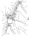
- a docking device 1 of a ship 2 is represented on the Figures 4 to 6 .
- This docking device 1 comprises locking means 5 comprising two jaws 50a and 50b ( figure 4 ) integral with a floating pontoon 3, and engagement means 20 integral with the ship 2 to dock at the pontoon 3.
- the pontoon 3 comprises means for moving the locking means 5 on the pontoon 3.
- the displacement means comprise a rail 31 which extends over at least a portion of the length of the pontoon 3.
- rail 31 has a section of substantially parallelepipedal shape and is an integral part of the pontoon 3 (it can be fixed permanently to the latter in an alternative).
- a sliding carriage 32 is mounted to move in translation on the rail 31 and is particularly intended to support the locking means 5 of the docking device 1.
- the carriage 32 is connected upstream and downstream to a floating jetty (" catway " in English) 33, extending perpendicularly to the pontoon 3, via a crossbar 34, so that the entire device mooring 1 can be moved along the pontoon 3 on the rail 31.
- the displacement of the assembly formed by the carriage 32 and the piers 33 can be carried out manually or with the aid of a motor (not shown), and is facilitated by the use of a plurality of wheels 35.
- a locking system (not shown) of the position of the docking device 1 on the rail 31 is implemented in order to secure the device and to avoid lateral movements of the docking device 1 due to the swell, in particular.
- the docking device 1 comprises a chassis 4 carrying the locking means 5, the chassis 4 being integral with the carriage 32.
- the frame 4 comprises a central upright 41 extending perpendicular to the carriage 32, and carries centering / guiding means which are in the form of two side walls, or flaps, 42. These flaps 42 are of rectangular shape and extend towards the ship to moor by forming a V.
- each of the flaps 42 of the frame 4 is fixedly mounted on the upright 41 by means of at least one support element 43.
- each of the flaps 42 is integral with the upright 41 by means of two support elements 43 comprising a base 431 and two branches 432 (forming a Y). More specifically, the flaps 42 are integral with the branches 432 of the support element 43.
- the flaps 42 are intended to direct and / or center the engagement means 20 carried by the ship 2 towards the locking means 5 disposed on the pontoon 3.
- the frame 4 has, at the rear of the upright 41, and more precisely at the joint of the two branches 432 of the support member 43, a circular opening in which is mounted a tube 54 carrying the jaws 50a, 50b, as illustrated. on the figure 6 .
- the structure of the jaws 50a, 50b is identical to that described in the first embodiment.
- the locking means 5 thus use two jaws 50a 50b which are secured to the frame 4 by means of two pairs of brackets 51a, 51b and 52a, 52b.
- the upper brackets 51a, 51b are rotatable relative to each other through a pivot connection, or axis of rotation, 511 located at a first end of each of the upper brackets 51a, 51b.
- the lower brackets 52a, 52b are likewise rotatable relative to one another via a pivot connection, or axis of rotation, 521 (not visible), located at a first end. each of the lower brackets 52a, 52b.
- the second end of the lower brackets 52a, 52b and upper brackets 51a, 51b are connected to each other by means of a tie bar 53a, 53b.
- the brackets and the tie bars thus form the jaws 50a and 50b.
- the carrier tube 54 cooperating with the frame 4, makes it possible to connect the axis of rotation 511 of the upper brackets 51a and 51b to the axis of rotation 521 of the lower brackets 52a and 52b.
- Such a carrier tube 54 also makes it possible to stiffen / reinforce the structure of the locking means 5.
- the docking device 1 comprises actuating means 6 locking means 5 comprising a support member (or roller) 61 on which are mounted articulated about the same axis of rotation 621 two levers, or rods, 62a and 62b, which extend, forming a V variable angle, towards the ship 2 to moor.
- actuating means 6 locking means 5 comprising a support member (or roller) 61 on which are mounted articulated about the same axis of rotation 621 two levers, or rods, 62a and 62b, which extend, forming a V variable angle, towards the ship 2 to moor.
- the rods 62a, 62b are respectively integral at their other end with a lower bracket 52a, 52b. These brackets 52a, 52b are rotatably mounted on the connecting rods 62a, 62b respectively about an axis of rotation which is located near their corner / right angle.
- the support member 61 is secured to a movable portion 631 of a profile 63 extending parallel to the edge of the pontoon 3.
- the movable portion 631 is able to shift, that is to say, to move in translation perpendicular to the longitudinal axis of the section 63 according to whether it is desired to open or close the jaws 50a, 50b.
- the profile 63 is integral with the carriage 32 and the cross members 34, so as to allow the displacement of the mooring device 1 on the rail 31.
- the displacement in translation of the movable portion 631 of the profile 63 is implemented by an actuator 64.
- the figure 6 illustrates the implementation of a manual actuator 64, the latter being pivotally mounted on each of the bases 431 of the support member 43 of the frame 4.
- the bases 431 each have a circular opening allowing the passage of an axis 641, extending parallel to the tube 54.
- the axis 641 is integral at its lower end with a cam 642 and at its upper end with a handle 643. .
- the axis 641 pivots and causes the cam 642 to rotate.
- the rotation of the cam 642 causes the movable portion 631 to move by means of a rod. 644 connecting the cam 642 and the movable portion 631. More specifically, the movable portion 631, which is here disposed along the longitudinal axis of the section 63, shifts and moves towards the cam 642.
- the angle between the connecting rods 62a and 62b decreases which causes the opening / removal of the jaws 50a, 50b. It is understood that the movement of the handle 643 in the other direction makes it possible to close / close the jaws 50a, 50b.
- the actuator 64 thus allows the jaws 50a, 50b to move between the open position, in which the hook bars 53a, 53b are spaced apart from one another allowing the engagement means 20 to pass through (the upper brackets and lower respectively forming a "W") and a closed position (as illustrated on the figures 5 and 6 ), wherein the tie bars 53a, 53b are brought together and maintain the engagement means 20 (the upper and lower brackets respectively forming a "U").
- the assembly comprising the actuator 64, the drive cam 642, the pair of connecting rods 62a, 62b, the support member 61 and the movable portion 631 form the actuating means 6 of the locking means 5 of the device mooring 1.
- the locking means 5 are intended to cooperate with engagement means 20.
- the engagement means 20 comprise an axis 21 for connecting the ship 2 to moor to a ring 22 which has an inner lumen 221.
- the light 221 is intended to cooperate with a manual or automatic pole to bring the ship 2 locking means 5, or away.
- the light 221 is formed by a circular opening extended by two grooves on the opposite edges located in the extension of the axis 21. Of course, this light 221 may be circular or have another shape.
- the engagement means 20 also comprise a rod, or central portion, 23 of reduced width. A first end of the rod 23 is integral with the ring 22 and a second end of the rod 23 is connected to a stud 24.
- the mooring of the ship 2 to the pontoon 3 is obtained when the stud 24 is inserted between the jaws 50a, 50b open and the latter are brought together to grip (with a game) the central rod 23, as shown in the figure 5 .
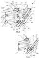
- a docking device 1 of a ship 2 is represented on the Figures 8A and 8B .
- This mooring device 1 comprises locking means 5 composed of two jaws 50a, 50b integral with a floating pontoon 3, and engagement means 20 integral with the ship 2 to be moored to the pontoon 3.
- This third embodiment differs from the first two embodiments described above in that the jaws 50a and 50b of the locking means 5 remain in the closed position during docking and undocking of the ship 2.
- the pontoon 3 has means for moving the locking means 5 along the pontoon 3.
- These displacement means comprise a rail 31 which extends over at least a portion of the length of the pontoon 3.
- a sliding carriage 32 is mounted to move in translation on the rail 31 and is particularly intended to support the locking means 5 of the docking device 1.
- the carriage 32 is connected upstream and downstream to a floating jetty (" catway " in English) 33, extending perpendicularly to the pontoon 3, via a cross member 34 so that the entire device of mooring 1 can be moved along the pontoon 3 on the rail 31.
- the displacement of the assembly formed by the carriage 32 and the piers 33 is facilitated by the implementation of a plurality of wheels 35.
- a locking system (not shown) of the position of the docking device 1 on the rail 31 is implemented in order to secure the device and to avoid lateral movements due to the swell, in particular.
- the mooring device 1 comprises a chassis 4 integral with the carriage 32 and intended to carry the locking means 5.
- the chassis 4 comprises a central amount 41 (visible at the Figure 8B ) extending perpendicular to the carriage 32, and has two side walls, or flaps, 42, of substantially rectangular shape, extending towards the vessel to moor and forming a V.
- each of the flaps 42 of the frame 4 is mounted fixed on the upright 41 by means of at least one support member 43.
- each of the flaps 42 is integral with the upright 41 by means of two support members 43 of substantially Y (and comprising a base 431 and two branches 432). More specifically, the flaps 42 are integral with the branches 432 of the support element 43.
- the flaps 42 are intended to direct and / or center the engagement means 20 carried by the ship 2 towards the locking means 5 disposed on the pontoon 3.
- the frame 4 has, at the rear of the upright 41, and more precisely at the joint of the two branches 432 of the support member 43, a circular opening in which is mounted a tube 54 carrying the jaws 50a, 50b.
- the structure of the jaws 50a, 50b is identical to those described in the first two embodiments.
- the locking means 5 thus use two jaws 50a and 50b, secured to the frame 4 by means of two pairs of brackets 51a, 51b and 52a, 52b (not visible).
- the brackets and the tie bars 53a, 53b thus form the jaws 50a and 50b.
- the engagement means 20 are in two parts removable. More specifically, the engagement means 20 comprise a base, or first fixed part, 27 integral with the ship 2, and a removable part, or second part 26, intended to cooperate with the jaws 50a, 50b of the locking means 5.
- the base 27, which is attached to the ship 2, has an engagement pin 271 extending in the extension of the nose of the vessel 2.
- the engagement pin 271 is intended to cooperate with a circular housing 261 formed in the base 262 of the removable part 26 so as to secure the base 27 to the removable part 26.
- the removable portion 26 further has a ring 22 comprising an inner lumen 221.
- the light 221 is intended to cooperate with a manual or automatic pole allowing to bring the ship 3 closer to or away from the locking means 5.
- the light 221 is formed by a circular opening extended by two grooves on the opposite edges located in the extension of the circular housing 261.
- this light 221 may be circular or have another shape.
- the removable portion 26 also comprises a rod or central portion 23 of reduced width.
- a first end of the rod 23 is integral with the ring 22 and a second end of the rod 23 is connected to an arrow 24.
- a docking device 1 of a ship 2 is represented on the Figures 9A and 9B .
- This mooring device 1 comprises locking means 5 comprising two jaws 50a, 50b integral with a floating pontoon 3, and engagement means 20 integral with the ship 2 to be moored to the pontoon 3.
- the jaws 50a and 50b of the locking means 5 remain in the closed position during docking and undocking of the ship 2.
- This fourth embodiment differs from the third embodiment described above in that the second portion 26 of the engagement means 20 of the ship 2, intended to cooperate with the jaws 50a, 50b means of 5, is mounted rotatably on the base, or fixed part 27 which is permanently fixed to the front tip of the ship 2. This second portion 26 is removably or not mounted on the fixed part 27.
- the pivoting portion 26 comprises a ring 22 having an inner lumen 221.
- the light 221 is intended to cooperate with a manual or automatic pole allowing the ship 2 to be moved closer to or away from the locking means 5.
- the light 221 is formed by a circular opening extended by two grooves on the opposite edges located in the extension of the base 27. Of course, this light 221 may be circular or have another shape.
- the pivoting portion 26 also comprises a rod or central portion 23 of reduced width.
- a first end of the rod 23 is integral with the ring 22 and a second end of the rod 23 is connected to an arrow 24.
- Mooring the vessel 2 to the pontoon 3 is simple and requires few operations.
- the pivoting part 26 is oriented vertically with respect to the upper surface of the deck of the ship 2 (as illustrated in FIG. Figure 9A ). This first orientation of the pivoting part 26 allows the arrow 24 to slide between the jaws 50a, 50b of the locking means 5 located on the pontoon 3.
- the pivoting portion 26 pivots 90 ° to move to the active position to lock / lock the boom 24 of the vessel 2 (as shown in FIG. Figure 9B ).
- the rod 23 of the engagement means is located between the hook bars 53a, 53b of the locking means 5.
- Pivoting of the pivoting part 26 is obtained by a manual action of the user.
- the pivoting can be automatic or triggered by a remote control located in the cockpit of the ship, for example.
- the actuating means 6 of the locking means 5 use an automatic actuator 65 comprising a motor 651.
- the motor 651 is intended to move the cam 652 in rotation, the latter acting on a rod 653 integral with the movable portion 631 so as to allow the shifting of the movable portion 631 with respect to the longitudinal axis of the section 63.
- the closure of the jaws can be initiated by the actuator when detection means (comprising one or more sensors) determine that the engagement means are correctly positioned between the jaws.
- the actuating means can be controlled by remote control means located, for example, in the control cabin of the ship.
- engagement means can be located at the rear or on the sides of the ship.
- the ring 22 of the engagement means may be replaced by a triangle-shaped element allowing optimized guidance of the jaws on each side of the rod during closure of the jaws.
- the engagement means 20 may not comprise a ring, the stud 34 being directly connected to the tip of the ship 2.
- the locking means may be carried by the ship and the engagement means may be integral with the pontoon.
- the mooring device according to the invention can in particular be implemented at sea, in a lake or river, on a pontoon or a quay of a marina (or a port arranged along a canal or a navigable river), for example. It is particularly, but not exclusively, suitable for recreational craft.
- the same pontoon may be equipped with several mooring devices, and include for example one or more mooring devices with manual actuator and / or one or more mooring devices with automatic actuator.
Landscapes
- Health & Medical Sciences (AREA)
- Chemical & Material Sciences (AREA)
- Life Sciences & Earth Sciences (AREA)
- Organic Chemistry (AREA)
- General Health & Medical Sciences (AREA)
- Medicinal Chemistry (AREA)
- Engineering & Computer Science (AREA)
- Proteomics, Peptides & Aminoacids (AREA)
- Public Health (AREA)
- Animal Behavior & Ethology (AREA)
- Veterinary Medicine (AREA)
- Biophysics (AREA)
- Biochemistry (AREA)
- Genetics & Genomics (AREA)
- Molecular Biology (AREA)
- Epidemiology (AREA)
- Pharmacology & Pharmacy (AREA)
- Ocean & Marine Engineering (AREA)
- General Engineering & Computer Science (AREA)
- Immunology (AREA)
- Mechanical Engineering (AREA)
- Gastroenterology & Hepatology (AREA)
- Bioinformatics & Cheminformatics (AREA)
- Reproductive Health (AREA)
- Combustion & Propulsion (AREA)
- Zoology (AREA)
- Cell Biology (AREA)
- Toxicology (AREA)
- Birds (AREA)
- General Chemical & Material Sciences (AREA)
- Environmental & Geological Engineering (AREA)
- Endocrinology (AREA)
- Chemical Kinetics & Catalysis (AREA)
- Pregnancy & Childbirth (AREA)
- Nuclear Medicine, Radiotherapy & Molecular Imaging (AREA)
- Dermatology (AREA)
- Ophthalmology & Optometry (AREA)
- Gynecology & Obstetrics (AREA)
- Civil Engineering (AREA)
- Structural Engineering (AREA)
Applications Claiming Priority (1)
| Application Number | Priority Date | Filing Date | Title |
|---|---|---|---|
| FR1558330A FR3040682B1 (fr) | 2015-09-08 | 2015-09-08 | Dispositif d'amarrage d'un navire a un poste d'amarrage d'un ponton et ponton correspondant |
Publications (1)
| Publication Number | Publication Date |
|---|---|
| EP3141470A1 true EP3141470A1 (de) | 2017-03-15 |
Family
ID=54783782
Family Applications (1)
| Application Number | Title | Priority Date | Filing Date |
|---|---|---|---|
| EP16185782.6A Withdrawn EP3141470A1 (de) | 2015-09-08 | 2016-08-25 | Vorrichtung zum vertäuen eines boots an einer anlegestelle eines bootsanlegers, und entsprechender bootsanleger |
Country Status (6)
| Country | Link |
|---|---|
| US (1) | US9926046B2 (de) |
| EP (1) | EP3141470A1 (de) |
| CN (1) | CN106494572A (de) |
| FR (1) | FR3040682B1 (de) |
| RU (1) | RU2016136135A (de) |
| SG (1) | SG10201607234RA (de) |
Cited By (2)
| Publication number | Priority date | Publication date | Assignee | Title |
|---|---|---|---|---|
| WO2021144442A1 (fr) | 2020-01-17 | 2021-07-22 | Naval Energies | Système d'amarrage d'une structure flottante sur un quai |
| NL2024235B1 (en) * | 2019-11-14 | 2021-07-29 | European Intelligence B V | Mooring system |
Families Citing this family (9)
| Publication number | Priority date | Publication date | Assignee | Title |
|---|---|---|---|---|
| CN107873598B (zh) * | 2017-12-07 | 2020-02-25 | 浙江海洋大学 | 一种海上养殖系统中的引导停泊单元 |
| CN107926798B (zh) * | 2017-12-07 | 2020-02-25 | 浙江海洋大学 | 一种海上养殖系统 |
| MX2021003284A (es) * | 2018-09-21 | 2021-05-31 | Dockstar Tech Zrt | Aparato de amarre automatico para embarcaciones. |
| CN109484571B (zh) * | 2018-09-27 | 2020-04-28 | 武汉船用机械有限责任公司 | 船舶系泊装置 |
| CN109398643B (zh) * | 2018-10-17 | 2019-10-08 | 青岛北海船舶重工有限责任公司 | 一种实现定位控制的系泊轨道制作方法 |
| CN111391973B (zh) * | 2020-03-27 | 2021-04-23 | 嵊州市观东机械厂 | 一种具有位置调整和收卷功能的船舶系泊装置 |
| RU2757696C1 (ru) * | 2020-11-02 | 2021-10-20 | Александр Владимирович Жуков | Способ швартовки судна и автоматизированное швартовое устройство |
| CN112758251B (zh) * | 2020-12-31 | 2021-12-10 | 深圳中科讯联科技股份有限公司 | 自动停泊装置及其控制方法、水上机器人及其控制方法 |
| CN117068317A (zh) * | 2023-07-25 | 2023-11-17 | 中国船舶集团青岛北海造船有限公司 | 一种机械臂联动式水上浮动单元抱桩系泊装置及方法 |
Citations (5)
| Publication number | Priority date | Publication date | Assignee | Title |
|---|---|---|---|---|
| DE932294C (de) * | 1952-08-20 | 1956-01-12 | Robert Wuerth | Vorrichtung zum kippfreien Anlegen von Booten |
| US5711242A (en) * | 1993-07-30 | 1998-01-27 | Gtm | Device for mooring a craft to a docking point |
| WO2009073897A2 (en) | 2007-10-31 | 2009-06-11 | Artur Duarte Da Silva Lopes | Docking apparatus |
| US7992508B1 (en) * | 2008-04-21 | 2011-08-09 | Norton Daniel A | Remotely operated watercraft docking mechanism having fuel saving and theft thwarting attributes |
| EP2520485A1 (de) * | 2011-05-03 | 2012-11-07 | Presign Holding B.V. | System und Verfahren zum Vertäuen eines schwimmenden Fahrzeugs an einem ortsfesten Objekt |
Family Cites Families (6)
| Publication number | Priority date | Publication date | Assignee | Title |
|---|---|---|---|---|
| US7131387B1 (en) * | 2004-06-29 | 2006-11-07 | John Czipri | Folding cleat with spring actuation |
| US7827924B1 (en) * | 2008-05-23 | 2010-11-09 | Perez Angel V | Boat mooring device |
| NL2003728C2 (nl) * | 2009-10-30 | 2011-05-03 | P & R Systems | Werkwijze voor het stabiliseren van een drijvend vaartuig tegen een stationair object. |
| US8689718B2 (en) * | 2010-03-01 | 2014-04-08 | Jeffrey Jerome Cichoski | Rigid quick connect mooring device |
| CN201694359U (zh) * | 2010-07-02 | 2011-01-05 | 百祥船舶机械有限公司 | 椭圆活动型系绳柱 |
| EP2818396B1 (de) * | 2013-06-25 | 2017-09-27 | Siemens Aktiengesellschaft | Wasserfahrzeug, Andocksystem und Andockstruktur |
-
2015
- 2015-09-08 FR FR1558330A patent/FR3040682B1/fr not_active Expired - Fee Related
-
2016
- 2016-08-25 EP EP16185782.6A patent/EP3141470A1/de not_active Withdrawn
- 2016-08-31 SG SG10201607234RA patent/SG10201607234RA/en unknown
- 2016-09-07 RU RU2016136135A patent/RU2016136135A/ru not_active Application Discontinuation
- 2016-09-07 CN CN201610808239.0A patent/CN106494572A/zh active Pending
- 2016-09-08 US US15/259,873 patent/US9926046B2/en not_active Expired - Fee Related
Patent Citations (5)
| Publication number | Priority date | Publication date | Assignee | Title |
|---|---|---|---|---|
| DE932294C (de) * | 1952-08-20 | 1956-01-12 | Robert Wuerth | Vorrichtung zum kippfreien Anlegen von Booten |
| US5711242A (en) * | 1993-07-30 | 1998-01-27 | Gtm | Device for mooring a craft to a docking point |
| WO2009073897A2 (en) | 2007-10-31 | 2009-06-11 | Artur Duarte Da Silva Lopes | Docking apparatus |
| US7992508B1 (en) * | 2008-04-21 | 2011-08-09 | Norton Daniel A | Remotely operated watercraft docking mechanism having fuel saving and theft thwarting attributes |
| EP2520485A1 (de) * | 2011-05-03 | 2012-11-07 | Presign Holding B.V. | System und Verfahren zum Vertäuen eines schwimmenden Fahrzeugs an einem ortsfesten Objekt |
Cited By (3)
| Publication number | Priority date | Publication date | Assignee | Title |
|---|---|---|---|---|
| NL2024235B1 (en) * | 2019-11-14 | 2021-07-29 | European Intelligence B V | Mooring system |
| WO2021144442A1 (fr) | 2020-01-17 | 2021-07-22 | Naval Energies | Système d'amarrage d'une structure flottante sur un quai |
| FR3106330A1 (fr) | 2020-01-17 | 2021-07-23 | Naval Energies | Système d’amarrage d’une structure flottante sur un quai |
Also Published As
| Publication number | Publication date |
|---|---|
| CN106494572A (zh) | 2017-03-15 |
| SG10201607234RA (en) | 2017-04-27 |
| FR3040682A1 (fr) | 2017-03-10 |
| US20170066505A1 (en) | 2017-03-09 |
| FR3040682B1 (fr) | 2019-04-19 |
| US9926046B2 (en) | 2018-03-27 |
| RU2016136135A (ru) | 2018-03-14 |
Similar Documents
| Publication | Publication Date | Title |
|---|---|---|
| EP3141470A1 (de) | Vorrichtung zum vertäuen eines boots an einer anlegestelle eines bootsanlegers, und entsprechender bootsanleger | |
| EP3526111B1 (de) | Schiff mit einer einrichtung zum starten und rückgewinnen von fahrzeugen | |
| EP2398700B1 (de) | Einrichtung zum handhaben eines segels | |
| CA2875597C (fr) | Systeme de mise a l'eau et de recuperation d'engins sous-marins, notamment d'engins sous-marins tractes | |
| WO2012076515A1 (fr) | Système de mise à l'eau et de récupération d'engins sous-marins, notamment d'engins sous-marins tractés | |
| CA2853392C (fr) | Installation d'ancrage au sol pour une plateforme flottante | |
| EP1580115B1 (de) | Einrichtung zum Anheben und Absetzen eines Unterwasserfahrzeugs | |
| EP3209546B1 (de) | System zum aussetzen und bergen von see- und unterseevorrichtungen mit unterstützung durch kippbare schutzkomponenten | |
| EP0138928B1 (de) | Abnehmbarer und klappbarer radträger insbesondere für schlauchboote | |
| FR3062844A1 (fr) | Systeme de mise a l'eau et de recuperation d'un engin propulse depuis le pont d'un navire porteur | |
| FR3040365B1 (fr) | Ameliorations de voiliers | |
| FR2825341A1 (fr) | Vehicule a propulsion eolienne tel qu'un bateau a voile | |
| FR3078055A1 (fr) | Dispositif de quille pendulaire pour navire a voiles | |
| EP4177148B1 (de) | Segelschiff mit einem übergangsstück zum heben und heben des segels | |
| FR3131264A1 (fr) | Systeme pour la manoeuvre d un engin marin | |
| EP4559799A1 (de) | Start- und rückholvorrichtung für ein wasserfahrzeug mit einem gespannten seil | |
| EP4559798A1 (de) | Vorrichtung zum starten und bergen eines wasserfahrzeugs mit einem dreieckigen kabel | |
| FR2824530A1 (fr) | Planche a voile perfectionnee | |
| FR3161195A1 (fr) | Bâtiment naval comprenant une structure flottante de lancement et de récupération d'un engin marin | |
| EP4353580A1 (de) | Plattform zum heben und heben von bootsanschlägen mit einem drehbaren und verschiebbaren hebe- und aushebe-gateway | |
| CA1274419A (fr) | Support de roue amovible et pliable notamment pour bateaux pneumatiques | |
| FR2939095A1 (fr) | Engin de reception d'embarcation equipe d'un dispositif anti-derive et dispositif anti-derive correspondant | |
| FR3154379A1 (fr) | Dispositif de récupération d'un engin sous-marin | |
| WO2020229765A1 (fr) | Dispositif de mise a l'eau et/ou de remontee d'une embarcation et vehicule comprenant un tel dispositif | |
| FR2740101A1 (fr) | Dispositif ultra-leger et embarquable pour la mise a l'eau des petits bateaux |
Legal Events
| Date | Code | Title | Description |
|---|---|---|---|
| PUAI | Public reference made under article 153(3) epc to a published international application that has entered the european phase |
Free format text: ORIGINAL CODE: 0009012 |
|
| AK | Designated contracting states |
Kind code of ref document: A1 Designated state(s): AL AT BE BG CH CY CZ DE DK EE ES FI FR GB GR HR HU IE IS IT LI LT LU LV MC MK MT NL NO PL PT RO RS SE SI SK SM TR |
|
| AX | Request for extension of the european patent |
Extension state: BA ME |
|
| 17P | Request for examination filed |
Effective date: 20170912 |
|
| RBV | Designated contracting states (corrected) |
Designated state(s): AL AT BE BG CH CY CZ DE DK EE ES FI FR GB GR HR HU IE IS IT LI LT LU LV MC MK MT NL NO PL PT RO RS SE SI SK SM TR |
|
| REG | Reference to a national code |
Ref country code: HK Ref legal event code: DE Ref document number: 1231026 Country of ref document: HK |
|
| 17Q | First examination report despatched |
Effective date: 20180102 |
|
| GRAP | Despatch of communication of intention to grant a patent |
Free format text: ORIGINAL CODE: EPIDOSNIGR1 |
|
| INTG | Intention to grant announced |
Effective date: 20180814 |
|
| STAA | Information on the status of an ep patent application or granted ep patent |
Free format text: STATUS: THE APPLICATION IS DEEMED TO BE WITHDRAWN |
|
| 18D | Application deemed to be withdrawn |
Effective date: 20190103 |
|
| REG | Reference to a national code |
Ref country code: HK Ref legal event code: WD Ref document number: 1231026 Country of ref document: HK |