EP3141475B1 - Systeme et procede de commande de pas de propulseur - Google Patents
Systeme et procede de commande de pas de propulseur Download PDFInfo
- Publication number
- EP3141475B1 EP3141475B1 EP16186515.9A EP16186515A EP3141475B1 EP 3141475 B1 EP3141475 B1 EP 3141475B1 EP 16186515 A EP16186515 A EP 16186515A EP 3141475 B1 EP3141475 B1 EP 3141475B1
- Authority
- EP
- European Patent Office
- Prior art keywords
- ltb
- pitch control
- control system
- crankshaft
- actuator
- Prior art date
- Legal status (The legal status is an assumption and is not a legal conclusion. Google has not performed a legal analysis and makes no representation as to the accuracy of the status listed.)
- Active
Links
Images


Classifications
-
- B—PERFORMING OPERATIONS; TRANSPORTING
- B64—AIRCRAFT; AVIATION; COSMONAUTICS
- B64C—AEROPLANES; HELICOPTERS
- B64C11/00—Propellers, e.g. of ducted type; Features common to propellers and rotors for rotorcraft
- B64C11/30—Blade pitch-changing mechanisms
-
- B—PERFORMING OPERATIONS; TRANSPORTING
- B64—AIRCRAFT; AVIATION; COSMONAUTICS
- B64C—AEROPLANES; HELICOPTERS
- B64C11/00—Propellers, e.g. of ducted type; Features common to propellers and rotors for rotorcraft
- B64C11/30—Blade pitch-changing mechanisms
- B64C11/38—Blade pitch-changing mechanisms fluid, e.g. hydraulic
- B64C11/40—Blade pitch-changing mechanisms fluid, e.g. hydraulic automatic
-
- F—MECHANICAL ENGINEERING; LIGHTING; HEATING; WEAPONS; BLASTING
- F02—COMBUSTION ENGINES; HOT-GAS OR COMBUSTION-PRODUCT ENGINE PLANTS
- F02C—GAS-TURBINE PLANTS; AIR INTAKES FOR JET-PROPULSION PLANTS; CONTROLLING FUEL SUPPLY IN AIR-BREATHING JET-PROPULSION PLANTS
- F02C9/00—Controlling gas-turbine plants; Controlling fuel supply in air- breathing jet-propulsion plants
-
- B—PERFORMING OPERATIONS; TRANSPORTING
- B64—AIRCRAFT; AVIATION; COSMONAUTICS
- B64C—AEROPLANES; HELICOPTERS
- B64C11/00—Propellers, e.g. of ducted type; Features common to propellers and rotors for rotorcraft
- B64C11/02—Hub construction
- B64C11/04—Blade mountings
- B64C11/06—Blade mountings for variable-pitch blades
-
- B—PERFORMING OPERATIONS; TRANSPORTING
- B64—AIRCRAFT; AVIATION; COSMONAUTICS
- B64C—AEROPLANES; HELICOPTERS
- B64C11/00—Propellers, e.g. of ducted type; Features common to propellers and rotors for rotorcraft
- B64C11/30—Blade pitch-changing mechanisms
- B64C11/306—Blade pitch-changing mechanisms specially adapted for contrarotating propellers
-
- B—PERFORMING OPERATIONS; TRANSPORTING
- B64—AIRCRAFT; AVIATION; COSMONAUTICS
- B64C—AEROPLANES; HELICOPTERS
- B64C11/00—Propellers, e.g. of ducted type; Features common to propellers and rotors for rotorcraft
- B64C11/46—Arrangements of, or constructional features peculiar to, multiple propellers
- B64C11/48—Units of two or more coaxial propellers
-
- B—PERFORMING OPERATIONS; TRANSPORTING
- B64—AIRCRAFT; AVIATION; COSMONAUTICS
- B64D—EQUIPMENT FOR FITTING IN OR TO AIRCRAFT; FLIGHT SUITS; PARACHUTES; ARRANGEMENT OR MOUNTING OF POWER PLANTS OR PROPULSION TRANSMISSIONS IN AIRCRAFT
- B64D27/00—Arrangement or mounting of power plants in aircraft; Aircraft characterised by the type or position of power plants
- B64D27/02—Aircraft characterised by the type or position of power plants
- B64D27/10—Aircraft characterised by the type or position of power plants of gas-turbine type
-
- F—MECHANICAL ENGINEERING; LIGHTING; HEATING; WEAPONS; BLASTING
- F01—MACHINES OR ENGINES IN GENERAL; ENGINE PLANTS IN GENERAL; STEAM ENGINES
- F01D—NON-POSITIVE DISPLACEMENT MACHINES OR ENGINES, e.g. STEAM TURBINES
- F01D7/00—Rotors with blades adjustable in operation; Control thereof
-
- F—MECHANICAL ENGINEERING; LIGHTING; HEATING; WEAPONS; BLASTING
- F02—COMBUSTION ENGINES; HOT-GAS OR COMBUSTION-PRODUCT ENGINE PLANTS
- F02C—GAS-TURBINE PLANTS; AIR INTAKES FOR JET-PROPULSION PLANTS; CONTROLLING FUEL SUPPLY IN AIR-BREATHING JET-PROPULSION PLANTS
- F02C3/00—Gas-turbine plants characterised by the use of combustion products as the working fluid
- F02C3/04—Gas-turbine plants characterised by the use of combustion products as the working fluid having a turbine driving a compressor
- F02C3/107—Gas-turbine plants characterised by the use of combustion products as the working fluid having a turbine driving a compressor with two or more rotors connected by power transmission
-
- F—MECHANICAL ENGINEERING; LIGHTING; HEATING; WEAPONS; BLASTING
- F02—COMBUSTION ENGINES; HOT-GAS OR COMBUSTION-PRODUCT ENGINE PLANTS
- F02C—GAS-TURBINE PLANTS; AIR INTAKES FOR JET-PROPULSION PLANTS; CONTROLLING FUEL SUPPLY IN AIR-BREATHING JET-PROPULSION PLANTS
- F02C6/00—Plural gas-turbine plants; Combinations of gas-turbine plants with other apparatus; Adaptations of gas-turbine plants for special use
- F02C6/20—Adaptations of gas-turbine plants for driving vehicles
- F02C6/206—Adaptations of gas-turbine plants for driving vehicles the vehicles being airscrew driven
-
- F—MECHANICAL ENGINEERING; LIGHTING; HEATING; WEAPONS; BLASTING
- F02—COMBUSTION ENGINES; HOT-GAS OR COMBUSTION-PRODUCT ENGINE PLANTS
- F02C—GAS-TURBINE PLANTS; AIR INTAKES FOR JET-PROPULSION PLANTS; CONTROLLING FUEL SUPPLY IN AIR-BREATHING JET-PROPULSION PLANTS
- F02C9/00—Controlling gas-turbine plants; Controlling fuel supply in air- breathing jet-propulsion plants
- F02C9/48—Control of fuel supply conjointly with another control of the plant
- F02C9/56—Control of fuel supply conjointly with another control of the plant with power transmission control
- F02C9/58—Control of fuel supply conjointly with another control of the plant with power transmission control with control of a variable-pitch propeller
-
- B—PERFORMING OPERATIONS; TRANSPORTING
- B64—AIRCRAFT; AVIATION; COSMONAUTICS
- B64D—EQUIPMENT FOR FITTING IN OR TO AIRCRAFT; FLIGHT SUITS; PARACHUTES; ARRANGEMENT OR MOUNTING OF POWER PLANTS OR PROPULSION TRANSMISSIONS IN AIRCRAFT
- B64D27/00—Arrangement or mounting of power plants in aircraft; Aircraft characterised by the type or position of power plants
- B64D27/02—Aircraft characterised by the type or position of power plants
- B64D27/16—Aircraft characterised by the type or position of power plants of jet type
-
- F—MECHANICAL ENGINEERING; LIGHTING; HEATING; WEAPONS; BLASTING
- F05—INDEXING SCHEMES RELATING TO ENGINES OR PUMPS IN VARIOUS SUBCLASSES OF CLASSES F01-F04
- F05D—INDEXING SCHEME FOR ASPECTS RELATING TO NON-POSITIVE-DISPLACEMENT MACHINES OR ENGINES, GAS-TURBINES OR JET-PROPULSION PLANTS
- F05D2220/00—Application
- F05D2220/30—Application in turbines
- F05D2220/32—Application in turbines in gas turbines
- F05D2220/323—Application in turbines in gas turbines for aircraft propulsion, e.g. jet engines
-
- F—MECHANICAL ENGINEERING; LIGHTING; HEATING; WEAPONS; BLASTING
- F05—INDEXING SCHEMES RELATING TO ENGINES OR PUMPS IN VARIOUS SUBCLASSES OF CLASSES F01-F04
- F05D—INDEXING SCHEME FOR ASPECTS RELATING TO NON-POSITIVE-DISPLACEMENT MACHINES OR ENGINES, GAS-TURBINES OR JET-PROPULSION PLANTS
- F05D2240/00—Components
- F05D2240/35—Combustors or associated equipment
-
- F—MECHANICAL ENGINEERING; LIGHTING; HEATING; WEAPONS; BLASTING
- F05—INDEXING SCHEMES RELATING TO ENGINES OR PUMPS IN VARIOUS SUBCLASSES OF CLASSES F01-F04
- F05D—INDEXING SCHEME FOR ASPECTS RELATING TO NON-POSITIVE-DISPLACEMENT MACHINES OR ENGINES, GAS-TURBINES OR JET-PROPULSION PLANTS
- F05D2260/00—Function
- F05D2260/70—Adjusting of angle of incidence or attack of rotating blades
- F05D2260/76—Adjusting of angle of incidence or attack of rotating blades the adjusting mechanism using auxiliary power sources
-
- F—MECHANICAL ENGINEERING; LIGHTING; HEATING; WEAPONS; BLASTING
- F05—INDEXING SCHEMES RELATING TO ENGINES OR PUMPS IN VARIOUS SUBCLASSES OF CLASSES F01-F04
- F05D—INDEXING SCHEME FOR ASPECTS RELATING TO NON-POSITIVE-DISPLACEMENT MACHINES OR ENGINES, GAS-TURBINES OR JET-PROPULSION PLANTS
- F05D2260/00—Function
- F05D2260/70—Adjusting of angle of incidence or attack of rotating blades
- F05D2260/79—Bearing, support or actuation arrangements therefor
-
- F—MECHANICAL ENGINEERING; LIGHTING; HEATING; WEAPONS; BLASTING
- F05—INDEXING SCHEMES RELATING TO ENGINES OR PUMPS IN VARIOUS SUBCLASSES OF CLASSES F01-F04
- F05D—INDEXING SCHEME FOR ASPECTS RELATING TO NON-POSITIVE-DISPLACEMENT MACHINES OR ENGINES, GAS-TURBINES OR JET-PROPULSION PLANTS
- F05D2270/00—Control
- F05D2270/60—Control system actuates means
- F05D2270/64—Hydraulic actuators
-
- Y—GENERAL TAGGING OF NEW TECHNOLOGICAL DEVELOPMENTS; GENERAL TAGGING OF CROSS-SECTIONAL TECHNOLOGIES SPANNING OVER SEVERAL SECTIONS OF THE IPC; TECHNICAL SUBJECTS COVERED BY FORMER USPC CROSS-REFERENCE ART COLLECTIONS [XRACs] AND DIGESTS
- Y02—TECHNOLOGIES OR APPLICATIONS FOR MITIGATION OR ADAPTATION AGAINST CLIMATE CHANGE
- Y02T—CLIMATE CHANGE MITIGATION TECHNOLOGIES RELATED TO TRANSPORTATION
- Y02T50/00—Aeronautics or air transport
- Y02T50/60—Efficient propulsion technologies, e.g. for aircraft
Definitions
- the present subject matter relates generally to variable pitch control systems and methods for gas turbine engine propellers, and more particularly to systems and methods for minimizing stress loads of pitch control.
- Gas turbine engines generally include a core engine powering a turbine to rotate one or more fan or propeller blade.
- One type of gas turbine engine known as an "open rotor” design, operates similarly to a conventional turbofan and turboprop designs, but with fuel efficiency that is superior to both.
- a turbofan engine operates on the principle that a central gas turbine core drives a bypass fan, the fan being located at a radial location between a nacelle of the engine and the engine core.
- a "bypass" propeller is mounted outside of an engine's nacelle. This permits the propeller to act on larger volumes of air and generate more thrust than with conventional turbofan engine.
- the "bypass" propeller includes two counter-rotating rotor assemblies, each rotor assembly carrying an array of propeller blades located outside the engine nacelle.
- a pitch control system may be attached to the propellers in order to alter the propellers' pitch angle according to desired flight characteristics.
- FR 2 992 703 A1 discloses an exemplary system for changing the pitch of the blades of a turboprop propeller of an aircraft equipped a bearing with lubrication means.
- GB 2 492 882 A discloses another exemplary device for controlling the pitch of turboprop fan blades.
- GB 2 493 980 A describes a pitch change mechanism 40 for an open rotor gas turbine engine 10.
- Optimum performance requires such systems to have a high-degree of accuracy.
- optimum performance may require the pitch angle of multiple propeller blades to be altered in unison.
- repeated or irregular pitch alterations may subject the pitch control system to excessive stresses or harmful loads. Over time, these stresses may decrease system accuracy or lead to engine failure.
- Current systems fail to adequately minimize friction and stress.
- their attempted synchronization of pitch alterations can be unreliable.
- pitch control systems and methods are desired.
- pitch control systems and methods for gas turbine engines that minimize operational stresses, increase accuracy, and allow for uniform pitch alterations would be advantageous.
- a propeller pitch control system and method is generally provided that minimizes circumferential loads applied to the system.
- the pitch control system includes an annular actuator mounted to a static engine frame about a central axis.
- the annular actuator is able to translate along a path parallel to the central axis.
- a load transfer bearing (LTB) is translationally fixed to the actuator, while a crank rod first end is pivotally attached to the LTB.
- a crank rod second end is pivotally attached to a propeller blade crankshaft.
- a radial pin extends outward from the LTB, and a guide shaft is pivotally attached to the radial pin to direct the radial pin along an arcuate path relative to a rotor frame upon translation of the annular actuator.
- a gas turbine engine in accordance with another embodiment, includes a static frame extending along a central axis and a rotor frame rotatably mounted to a static frame about the central axis. Also included is a plurality of circumferential propeller blade assemblies, at least one blade assembly including a variable pitch propeller blade and a crankshaft to direct pivotal movement of the blade about a discrete radial axis.
- An annular actuator is mounted to the static frame and is translatable along a path parallel to the central axis.
- a load transfer bearing (LTB) is translationally fixed to the actuator, while a crank rod first end is pivotally attached to the LTB.
- a crank rod second end is pivotally attached to a propeller blade crankshaft.
- a radial pin extends outward from the LTB, and a guide shaft is pivotally attached to the radial pin to direct the radial pin along an arcuate path relative to a rotor frame upon translation of the annular actuator.
- a method of changing propeller pitch includes the steps of supplying a linear input force at an annular actuator in a direction parallel to a central axis, thereby initiating a linear input movement at a load transfer bearing (LTB).
- the LTB is included in a pitch control system that includes the annular actuator mounted to the static frame, a radial pin extending from the LTB, and a guide shaft pivotally attached to the radial pin.
- the LTB is disposed about the annular actuator.
- a converting step converts the linear input movement to a roto-translation movement, including directing the LTB along an arcuate path relative to the rotor frame.
- Another step includes transferring the roto-translation movement to the crankshaft along a crank rod positioned between the LTB and the crankshaft, including transmitting a longitudinal displacement component to the crankshaft, and pivoting the at least one propeller blade about the radial axis according to the longitudinal displacement transmitted to the crankshaft.
- upstream refers to the relative flow direction with respect to fluid flow in a fluid pathway.
- upstream refers to the flow direction from which the fluid flows
- downstream refers to the flow direction to which the fluid flows.
- the terms “axial” or “axially” refer to a dimension along a longitudinal axis of an engine.
- the terms “radial” or “radially” refer to a dimension extending between a center longitudinal axis of the engine and an outer engine circumference.
- the term “forward” used in conjunction with “axial” or “axially” refers to a direction toward the engine inlet, or a component being relatively closer to the engine inlet as compared to another component.
- the terms “rear” or “aft” used in conjunction with “axial” or “axially” refers to a direction toward the engine nozzle, or a component being relatively closer to the engine nozzle as compared to another component.
- the positional terms “above”/"below,” “upward”/ “downward,” “outer”/”inner,” and “outward”/”inward” refer to radial positioning and direction relative to the central axis.
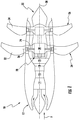
- FIG. 1 illustrates an exemplary open rotor gas turbine engine 10 defining a central axis 30.
- the open rotor gas turbine engine 10 may be configured as a tractor (rotors ahead of the engine in a pulling configuration), or as a pusher (shown).
- a tractor rotors ahead of the engine in a pulling configuration
- a pusher shown
- FIG. 1 illustrates an exemplary open rotor gas turbine engine 10 defining a central axis 30.
- the open rotor gas turbine engine 10 may be configured as a tractor (rotors ahead of the engine in a pulling configuration), or as a pusher (shown).
- FIG. 1 illustrates an exemplary open rotor gas turbine engine 10 defining a central axis 30.
- the open rotor gas turbine engine 10 may be configured as a tractor (rotors ahead of the engine in a pulling configuration), or as a pusher (shown).
- FIG. 1 illustrates an exemplary open rotor gas turbine engine 10 defining
- the gas turbine engine 10 incorporates one or more compressors 14, a combustor 16, and one or more turbines 18, 20.
- a low-pressure power turbine 20 is operably joined to an epicyclical gearbox 28 which, in turn, is operably joined to counter-rotating unducted rotor assemblies 24, 26.
- a compressible fluid e.g., gas
- the flow of a compressible fluid (e.g., gas) stream F begins inside nozzle of the nacelle 12. From there, the gas stream travels through the one or more compressors 14 before being ignited with a fuel at the annular combustor 16. The combustion rotates the high-pressure turbine 18 and the low-pressure turbine 20 before being expelled at the exhaust 22. Rotation of the low-pressure turbine 20 rotates the gearbox 28 which then rotates the counter-rotating rotor assemblies 24, 26.
- a compressible fluid e.g., gas
- the propeller blades 32, 34 of the forward and aft propellers are of the variable setting angle type (i.e. they can be oriented about their respective radial pivot axes 36 by virtue of a system 38 for changing or orienting the pitch of the blades) so that the blades assume an optimal angular position according to the operating conditions of the engine and the relevant flight phases.
- a system 38 for changing or orienting the pitch of the blades so that the blades assume an optimal angular position according to the operating conditions of the engine and the relevant flight phases.
- the pitch control system 38 for orienting blades associated with the forward rotor assembly 24 will be described.
- the aft rotor assembly 26, which is not shown in FIGS. 2-6 can be provided with a system for orienting blades that is similar or different to that described hereafter with reference to the forward rotor assembly 24.
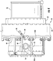
- the system 38 for controlling the pitch of the propeller blades (and thus their setting angle) is provided inside the engine 10, in the internal space positioned between the static frame 40 and the rotatable rotor frame 42, so as to vary the angular position of the blades and, thus, the pitch of the propeller.
- the pitch control system 38 comprises an annular actuator 44 that moves linearly (i.e., translates) along the central axis 30 of the engine.
- the actuator 44 surrounds a cylinder housing 46 and is able to translate back and forth therealong to vary the actuator's translation length. Since, the actuator 44 is mounted to the static frame 40, the translation length may be defined parallel to the central axis 30. Generally, as the translation length increases, the actuator's axial position is moved rearward. As the translation length decreases, the actuator's axial position is moved forward toward the engine nozzle. As will be described below, the actuator's translation length is operably tied to the pitch of the propeller. Therefore, translation length of the actuator 44 may be selected according the desired pitch angle 84A, 84B of the propeller.
- stops 48 are provided in the form of a shoulder 48A and a ring 48B to prevent actuator over travel (i.e., limit translation length).
- a piston 49 is positioned around the cylinder housing 46 and extends linearly along the axis 30, under the direction of an actuator control (not shown). The piston 49 provides a motive input force when translation of the actuator 44 is desired.
- the piston 49 is driven by a hydraulic fluid, although additional or alternative embodiments may include a magnetic actuator motor (not shown) to propel the piston 49 parallel to the central axis 30.
- a load transfer bearing (LTB) 50 is mounted on the actuator 44 and generally follows the same axial movements.
- Linear translation of the actuator 44 compels the LTB forward or aft along the central axis 30 according to actuator's translation length.
- the LTB 50 is able to move axially with respect to the static frame 40, while remaining translationally fixed to the actuator 44.
- the LTB 50 has a discrete inner race 52 and outer race 54.
- the inner race 52 of certain embodiments is positioned above the actuator 44 as an annular ring.
- the outer race 54 can be an annular ring positioned above, and concentric with, the inner race 52.
- the two races 52, 54 shown are translationally fixed. Axial movement of the inner race 52 is, therefore, mirrored by the outer race 54 during pitch change operations. However, rotational movement is not necessarily copied.
- the outer race 54 is able to rotate about the central axis 30 independently (i.e., rotationally free) of the inner race 52.
- the radial distance between the LTB races 52, 54 is fixed for some embodiments.
- One or more bearing rings 56 may be positioned between the races 52, 54 in order to support that distance.
- Optional embodiments of the bearing rings 56 include an inner track 58 and outer track 60 holding a row of ball bearings 62 to reduce friction.
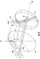
- One or more guide shafts 64 joins the LTB 50 to the rotor frame 42.
- a radial pin 66 extends outward from the outer race 54 and couples with the guide shaft 64.
- a guide shaft 64 may be anchored to the rotor frame 42 such that rotation of the rotor frame 42 causes simultaneous rotation of the guide shaft 64.
- the guide shaft 64 includes a fixed length 68.
- the fixed length 68 is defined by a rigid bar extending between the radial pin 66 and a rotor frame anchor point 70.
- a pivotal connection may be formed at both the pin 66 and the anchor point 70 (e.g., a yoke and pin joint, as illustrated at FIG. 2 ).
- the guide shaft 64 constrains the radial pin's positioning relative to the rotor frame 42. Since the rotor frame 42 is translationally static relative to the static frame 40, the guide shaft 64 directs the movement of the radial pin 66 (and thereby, the movement of the outer race 54) during the actuator's translation. Specifically, and as will be described below, translation of the actuator 44 causes the pin 66 to be directed along a set arcuate path 86 relative to the rotor frame 42. In optional embodiments, the arcuate path is defined radially by the guide shaft length 68 and anchor point 70.
- the guide shaft length 68 and arcuate path 86 are chosen to harmonically match (i.e., form a preselected relationship according to a movement frequency of) the distance between a set point J on the LTB 50 and a portion of the propeller blade 32.
- crank rods 72 joining the LTB outer race 54 to individual propeller blades 32.
- the crank rods 72 each include a rigid body extending longitudinally to connect the LTB 50 to the propeller blades 32.
- the propeller blades 32 each include a propeller support column 74 which extends along and rotates about the radial axis 36.
- a crankshaft 76 may extend outward from the propeller support column 74 (i.e., in a radial direction relative to the radial axis 36) and rotate about the axis 36.
- one end of the crankshaft is potentially fixed to the support column 74, an opposite end may include a journal 78 pivotally attached to the crank rod 72.
- the crank rod 72 is rotatably yoked to both the crankshaft 76 and LTB outer race 54 at opposite first and second ends 80, 82.
- at least two pin and yoke assemblies 81A, 81B are provided in some embodiments, as shown.
- One pin and yoke assembly 81A joins the crank rod first end 80 with the crankshaft 76.
- the other pin and yoke assembly 81B joins the crank rod second end 82 with the outer race 54.
- the crank rod 72 may define a set length.
- the crank rod 72 may further define a predetermined distance between the LTB 50 and the crankshaft journal 78. As shown in FIG.
- the guide shaft fixed length 68 is harmonically matched to the predetermined distance (e.g., the set length of the crank rod) such that the roto-translational movement of the LTB outer race 54 controls the pivotal rotation of the crankshaft 76 at the journal 78.
- the crank rod 72 of such embodiments is maintained in a predetermined pivotal range ⁇ relative to the central axis 30 during both forward and aft translation.
- the pivotal range ⁇ includes a radial range ⁇ R and a tangential range ⁇ T defined relative to the central axis 30.
- the radial range ⁇ R represents the radial deflection of the crank rod 72 relative the central axis 30' during operation
- the tangential range represents the tangential deflection of the crank rod 72 relative to the central axis 30' (wherein 30' is understood to be a reference axis parallel to the central axis 30, 36' is understood to be a reference axis parallel to the radial axis 36, and 36" is understood to be a reference axis perpendicular to the radial axis 36).
- the radial range ⁇ R is less than 15°, while the tangential range ⁇ T is less than 15°. In further embodiments, the radial range ⁇ R is less than 10°, while the tangential range ⁇ T is less than 10°. In still further embodiments, the radial range ⁇ R is less than 5°, while the tangential range ⁇ T is less than 5°. In optional embodiments, the radial range ⁇ R is less than 3°, while the tangential range ⁇ T is less than 3°. In the above-listed embodiments, the radial range ⁇ R may be equivalent to the tangential range ⁇ T , though it need not be.
- a desired pitch angle 84A, 84B may be selected, either manually or through an automated control unit (not shown).
- the annular actuator 44 may be translated to a new position.
- a linear input force translates the annular actuator 44 to an axial position corresponding to the selected pitch angle 84A, 84B.
- the corresponding axial position may be selected from a stored database, or calculated dynamically by the automated control unit.
- the mounted LTB 50 is similarly translated.
- the LTB inner race 52 and outer race 54 being translationally fixed to each other, move axially in unison.
- the translational motion supplied to the LTB inner race 52 is converted to a roto-translation movement at the LTB outer race 54.
- the outer race 54 is forced to rotate concentrically about the inner race 52 simultaneous to the uniform axial translation.
- the guide shaft 64 being anchored to the non-translating rotor frame 42, directs the outer race 54 and radial pin 66 along an arcuate path 86.
- the path 86 generally corresponds to a radius defined by the fixed guide length 68.
- the roto-translation movement is partially transferred to the crankshaft 76 and crank rod 72.
- the crank rod 72 is displaced longitudinally along the central axis 30 while its first and second ends 80, 82 are pivoted. Specifically, the second end 82 of the crank rod pivots relative to the rotation of the outer race 54, and the first end 80 pivots relative to the crankshaft journal 78.
- the guide shaft length 68 may be matched to the crank rod's own length to harmonize movement at both ends 80, 82 of the crank rod.
- the guide shaft length 68 and crank rod 72 are matched to maintain the crank rod 72 in a predetermined pivotal range ⁇ relative to central axis 30. In such embodiments a predetermined distance is maintained between the LTB 50 and the crankshaft journal 78.
- longitudinal displacement of the crank rod 72 is transferred to the crankshaft 76.
- crankshaft journal 78 Longitudinal displacement received by the crankshaft journal 78 pivots the crankshaft 76 about the radial axis 36. Since the crankshaft 76 is fixedly attached to the propeller support column 74, the blade 32 is simultaneously pivoted about the radial axis 36. Pivoting continues from the original desired pitch angle 84A until translation of the actuator 44 ceases and, therefore, until a new desired pitch angle 84B is reached.
- each crank rod 72 is joined to the LTB 50 at its second end 82 and joined to a discrete crankshaft 76 at its respective first end 80, as illustrated in FIG. 5 .
- Roto-translation at the LTB 50 translates the rods 72 uniformly and allows simultaneous axial movement between each rod 72.
Landscapes
- Engineering & Computer Science (AREA)
- Chemical & Material Sciences (AREA)
- Combustion & Propulsion (AREA)
- Aviation & Aerospace Engineering (AREA)
- Mechanical Engineering (AREA)
- General Engineering & Computer Science (AREA)
- Structures Of Non-Positive Displacement Pumps (AREA)
- Control Of Turbines (AREA)
Claims (10)
- Système de commande de pas (38) pour un ensemble rotor, ledit ensemble rotor ayant un châssis de rotor rotatif (42) monté sur un châssis de moteur statique (40) autour d'un axe central (30) et une pluralité de pales de propulseur (32, 34) montées de manière circonférentielle sur le châssis de rotor (42), le système de commande de pas (38) comprenant :un actionneur annulaire (44) pouvant être monté sur le châssis statique (40) autour de l'axe central (30), l'actionneur annulaire (44) pouvant subir une translation parallèlement à l'axe central (30) ;un palier de transfert de charge (LTB) (50) fixé en translation à l'actionneur (44) ;une tige de manivelle (72) ayant une première extrémité (80) attachée de manière pivotante au LTB (50) et une seconde extrémité (82) pouvant être fixée de manière pivotante à un vilebrequin de pale de propulseur (76) ;caractérisé en ce que le système de commande de pas (38) comprend en outre :un ergot radial (66) s'étendant à l'extérieur du LTB (50) ; etun arbre de guidage (64) attaché de manière pivotante à l'ergot radial (66) pour diriger, en fonctionnement, l'ergot radial (66) le long d'un chemin curviligne (86) par rapport au châssis de rotor (42) lors d'une translation de l'actionneur (44).
- Système de commande de pas (38) selon la revendication 1, dans lequel le LTB (50) comprend :un chemin de roulement intérieur (52) positionné autour de l'actionneur annulaire (44) etun chemin de roulement extérieur (54) monté en rotation et de manière concentrique sur le chemin de roulement intérieur (52).
- Système de commande de pas (38) selon la revendication 2, dans lequel le LTB (50) comprend en outre :
au moins une bague de palier (56) positionnée de façon radiale entre le chemin de roulement intérieur (52) et le chemin de roulement extérieur (54). - Système de commande de pas (38) selon l'une quelconque des revendications précédentes, dans lequel la tige de manivelle (72) comprend un premier ensemble étrier d'extrémité (81A) pouvant être fixé à un vilebrequin de pale de propulseur (76) et un second ensemble étrier d'extrémité (82A) attaché au LTB (50).
- Système de commande de pas (38) selon l'une quelconque des revendications précédentes, dans lequel l'arbre de guidage (64) inclut une longueur de guide fixée (68), dans lequel la tige de manivelle (72) peut être fixée à un tourillon distal (78) du vilebrequin (76) et maintient une distance longitudinale prédéterminée entre le tourillon et le LTB (50), et en outre dans lequel la longueur de guide (68) correspond de façon harmonique à la distance longitudinale prédéterminée, limitant de ce fait un mouvement de la tige de manivelle pouvant être mise en oeuvre (72) à une plage de pivotement prédéterminée (θR, θT).
- Système de commande de pas (38) selon l'une quelconque des revendications précédentes, dans lequel l'actionneur annulaire (44) inclut une longueur de translation variable pouvant être sélectionnée selon un angle de pas de propulseur souhaité (84).
- Système de commande de pas (38) selon l'une quelconque des revendications précédentes, comprenant en outre :
une pluralité de tiges de manivelle (72), chaque tige de manivelle (72) étant attachée de manière pivotante au LTB (50) au niveau de la première extrémité (80) et pouvant être attachée de façon discrète à un vilebrequin de pale de propulseur respectif (76) au niveau de la seconde extrémité (82), dans lequel une translation des tiges de manivelle (72) par rapport à l'axe central (30) est mécaniquement synchronisée. - Système de commande de pas (38) selon l'une quelconque des revendications précédentes, incluant un moteur à turbine à gaz (10), le moteur à turbine à gaz (10) comprenant :un compresseur (14) pouvant être monté autour du châssis statique (40) ;un dispositif de combustion (16) pouvant être positionné en aval du compresseur (14) pour recevoir un fluide comprimé en provenance de celui-ci ; etune turbine (18, 20) positionnée en aval du dispositif de combustion (16) et pouvant être joint de manière opérationnelle au châssis de rotor (42) de sorte qu'une rotation de la turbine (18, 20) est transmissible au châssis de rotor (42).
- Procédé pour commander un angle de pas d'une pluralité de pales de propulseur (32, 34), les pales de propulseur (32, 34) étant attachées à un châssis de rotor (42) et s'étendant le long d'axes radiaux respectifs autour d'un axe central (30), au moins une pale de propulseur incluant un vilebrequin (76) s'étendant depuis l'axe radial (36), le procédé comprenant les étapes de :fourniture d'une force d'entrée linéaire au niveau d'un actionneur annulaire (44) dans une direction parallèle à l'axe central (30), amorçant de ce fait un mouvement d'entrée linéaire au niveau d'un palier de transfert de charge (LTB) (50), dans lequel le LTB (50) est inclus dans un système de commande de pas (38) qui inclut l'actionneur annulaire (44) monté sur le châssis statique (40), le LTB (50) étant disposé autour de l'actionneur annulaire (44), un ergot radial (66) s'étendant à partir du LTB (50) et un arbre de guidage (64) attaché de manière pivotante à l'ergot radial (66) ;transformation du mouvement d'entrée linéaire en un mouvement de roto-translation, incluant l'orientation du LTB (50) le long d'un chemin curviligne (86) par rapport au châssis de rotor (42) ;transfert du mouvement de roto-translation au vilebrequin (76) le long d'une tige de manivelle (72) positionnée entre le LTB (50) et le vilebrequin (76), incluant la transmission d'un composant à déplacement longitudinal au vilebrequin (76) ; etpivotement de l'au moins une pale de propulseur autour de l'axe radial (36) selon le déplacement longitudinal transmis au vilebrequin (76).
- Procédé selon la revendication 9, dans lequel l'étape de transformation comprend en outre l'étape de rotation d'un chemin de roulement extérieur (54) du LTB (50) autour d'un chemin de roulement intérieur concentrique (52) du LTB (50), et dans lequel l'étape de transfert comprend en outre l'étape de translation de la tige de manivelle (72) dans une plage de pivotement prédéterminée (θR, θT).
Applications Claiming Priority (1)
| Application Number | Priority Date | Filing Date | Title |
|---|---|---|---|
| PL413823A PL226826B1 (pl) | 2015-09-03 | 2015-09-03 | Układ sterowania skokiem dozespołu wirnika, silnik turbospalinowy isposób sterowania katem skoku wielu łopat smigła |
Publications (2)
| Publication Number | Publication Date |
|---|---|
| EP3141475A1 EP3141475A1 (fr) | 2017-03-15 |
| EP3141475B1 true EP3141475B1 (fr) | 2018-10-17 |
Family
ID=56876927
Family Applications (1)
| Application Number | Title | Priority Date | Filing Date |
|---|---|---|---|
| EP16186515.9A Active EP3141475B1 (fr) | 2015-09-03 | 2016-08-31 | Systeme et procede de commande de pas de propulseur |
Country Status (7)
| Country | Link |
|---|---|
| US (1) | US10800512B2 (fr) |
| EP (1) | EP3141475B1 (fr) |
| JP (1) | JP2017100701A (fr) |
| CN (1) | CN106499520B (fr) |
| BR (1) | BR102016020320A2 (fr) |
| CA (1) | CA2940045A1 (fr) |
| PL (1) | PL226826B1 (fr) |
Families Citing this family (7)
| Publication number | Priority date | Publication date | Assignee | Title |
|---|---|---|---|---|
| FR2980770B1 (fr) * | 2011-10-03 | 2014-06-27 | Snecma | Turbomachine a helice(s) pour aeronef avec systeme pour changer le pas de l'helice. |
| US10933991B2 (en) * | 2018-06-18 | 2021-03-02 | Aurora Flight Sciences Corporation | Propulsors, aircraft including the propulsors, and methods of directing a fluid stream in a propulsor |
| FR3100272B1 (fr) * | 2019-08-27 | 2025-04-25 | Safran Aircraft Engines | Guignol pour un dispositif de calage variable d’une turbomachine |
| US11428160B2 (en) | 2020-12-31 | 2022-08-30 | General Electric Company | Gas turbine engine with interdigitated turbine and gear assembly |
| CN113123871B (zh) * | 2021-04-21 | 2022-04-22 | 南京航空航天大学 | 一种带箍喷气自驱动和叶尖涡轮驱动的对转桨扇发动机 |
| FR3123884B1 (fr) * | 2021-06-15 | 2024-05-03 | Safran Aircraft Engines | Systeme de changement de pas des pales d’une helice d’une turbomachine |
| US12078100B2 (en) | 2021-12-03 | 2024-09-03 | General Electric Company | Combustor size rating for a gas turbine engine using hydrogen fuel |
Family Cites Families (24)
| Publication number | Priority date | Publication date | Assignee | Title |
|---|---|---|---|---|
| GB559756A (en) | 1942-08-31 | 1944-03-03 | Llewellyn Lloyd Davies | Improvements in or relating to variable-pitch propellers |
| US3163231A (en) | 1963-04-29 | 1964-12-29 | United Aircraft Corp | Two-part pitch changing mechanism |
| NO120011B (fr) | 1967-03-22 | 1970-08-10 | Karlstad Mekaniska Ab | |
| US3873236A (en) * | 1973-12-26 | 1975-03-25 | Gen Electric | Fan with variable pitch blades and translating bearing actuation system |
| RU2101212C1 (ru) | 1996-10-17 | 1998-01-10 | Йелстаун Корпорейшн Н.В. | Система управления соосным реверсивным винтовентилятором |
| US6811376B2 (en) | 2002-03-19 | 2004-11-02 | Hamilton Sundstrand | Actuation system for a controllable pitch propeller |
| GB0614302D0 (en) | 2006-07-19 | 2006-08-30 | Rolls Royce Plc | An engine arrangement |
| US7758310B2 (en) | 2007-01-15 | 2010-07-20 | Sikorsky Aircraft Corporation | Translational thrust system for a rotary wing aircraft |
| FR2940247B1 (fr) | 2008-12-19 | 2011-01-21 | Snecma | Systeme d'helices contrarotatives entrainees par un train epicycloidal offrant une repartition de couple equilibree entre les deux helices |
| FR2946011B1 (fr) | 2009-05-29 | 2013-01-11 | Snecma | Dispositif a verin mobile pour la commande de l'orientation des pales de soufflante d'un turbopropulseur |
| FR2946010B1 (fr) * | 2009-05-29 | 2011-06-24 | Snecma | Dispositif a verin fixe pour la commande des pales de soufflante d'un turbopropulseur |
| US8172530B2 (en) * | 2009-06-09 | 2012-05-08 | Hamilton Sundstrand Corporation | Pitch change actuation system for a counter-rotating propeller |
| GB201000144D0 (en) | 2010-01-07 | 2010-02-24 | Rolls Royce Plc | Pitch Change Apparatus |
| US9718536B2 (en) | 2010-05-18 | 2017-08-01 | Hamilton Sundstrand Corporation | Counter-rotating open-rotor (CROR) |
| US8998127B2 (en) | 2010-09-09 | 2015-04-07 | Groen Brothers Aviation, Inc. | Pre-landing, rotor-spin-up apparatus and method |
| US8336290B2 (en) | 2010-09-30 | 2012-12-25 | General Electric Company | Pitch change apparatus for counter-rotating propellers |
| FR2973333B1 (fr) * | 2011-03-29 | 2014-08-01 | Snecma | Systeme pour changer le pas d'helices contrarotatives d'un turbomoteur |
| GB201108367D0 (en) | 2011-05-19 | 2011-06-29 | Rolls Royce Plc | Propulsion engine |
| FR2977862B1 (fr) * | 2011-07-13 | 2013-08-23 | Snecma | Dispositif de commande de l'orientation des pales de soufflante d'un turbopropulseur |
| GB2493980B (en) | 2011-08-26 | 2018-02-14 | Ge Aviat Systems Ltd | Pitch control of contra-rotating airfoil blades |
| FR2980770B1 (fr) * | 2011-10-03 | 2014-06-27 | Snecma | Turbomachine a helice(s) pour aeronef avec systeme pour changer le pas de l'helice. |
| FR2992703B1 (fr) | 2012-06-27 | 2015-01-30 | Snecma | Palier a moyen de lubrification et systeme pour changer le pas des pales d'une helice de turbopropulseur d'aeronef, equipe dudit palier |
| US8973864B2 (en) | 2012-08-02 | 2015-03-10 | Bell Helicopter Textron Inc. | Independent blade control system with hydraulic cyclic control |
| CN103754363B (zh) | 2014-02-11 | 2015-10-14 | 谷梦若 | 旋翼翼梢不变距且增升的直升机旋翼系统 |
-
2015
- 2015-09-03 PL PL413823A patent/PL226826B1/pl unknown
-
2016
- 2016-08-19 JP JP2016160923A patent/JP2017100701A/ja active Pending
- 2016-08-25 CA CA2940045A patent/CA2940045A1/fr not_active Abandoned
- 2016-08-30 US US15/251,350 patent/US10800512B2/en active Active
- 2016-08-31 CN CN201610771448.2A patent/CN106499520B/zh active Active
- 2016-08-31 EP EP16186515.9A patent/EP3141475B1/fr active Active
- 2016-09-02 BR BR102016020320A patent/BR102016020320A2/pt not_active Application Discontinuation
Non-Patent Citations (1)
| Title |
|---|
| None * |
Also Published As
| Publication number | Publication date |
|---|---|
| US20170066525A1 (en) | 2017-03-09 |
| PL413823A1 (pl) | 2017-03-13 |
| CN106499520B (zh) | 2020-10-16 |
| CN106499520A (zh) | 2017-03-15 |
| JP2017100701A (ja) | 2017-06-08 |
| BR102016020320A2 (pt) | 2017-03-07 |
| CA2940045A1 (fr) | 2017-03-03 |
| EP3141475A1 (fr) | 2017-03-15 |
| PL226826B1 (pl) | 2017-09-29 |
| US10800512B2 (en) | 2020-10-13 |
Similar Documents
| Publication | Publication Date | Title |
|---|---|---|
| EP3141475B1 (fr) | Systeme et procede de commande de pas de propulseur | |
| US10793255B2 (en) | System and method for controlling propeller pitch | |
| US12241377B2 (en) | Turbomachine module equipped with a blade pitch-changing system of a stator vane | |
| CN103874630B (zh) | 带有航空器螺旋桨的涡轮发动机,具有用于改变螺旋桨螺距的系统 | |
| US10543901B2 (en) | System and method for controlling propeller pitch | |
| US10119409B2 (en) | System for changing the pitch of the contra-rotating propellers of a turboshaft engine | |
| US11981419B2 (en) | Method and system for integrated pitch control mechanism actuator hydraulic fluid transfer | |
| CN116209821B (zh) | 设置有螺旋桨和偏置定子轮叶的涡轮机模块 | |
| US10604235B2 (en) | Pitch change module for turbine engine and corresponding turbine engine | |
| US9677408B2 (en) | System for controlling the pitch of the propeller blades of a turbomachine, and a turbomachine with a propeller for an aircraft with such a system | |
| US12553353B2 (en) | Pitch-change mechanism with pitch-locking device comprising a satellite roller screw | |
| US20240337195A1 (en) | Fan module having variable-pitch blades | |
| US10023320B2 (en) | Propulsion unit with a pair of propellers for an aircraft |
Legal Events
| Date | Code | Title | Description |
|---|---|---|---|
| PUAI | Public reference made under article 153(3) epc to a published international application that has entered the european phase |
Free format text: ORIGINAL CODE: 0009012 |
|
| STAA | Information on the status of an ep patent application or granted ep patent |
Free format text: STATUS: THE APPLICATION HAS BEEN PUBLISHED |
|
| AK | Designated contracting states |
Kind code of ref document: A1 Designated state(s): AL AT BE BG CH CY CZ DE DK EE ES FI FR GB GR HR HU IE IS IT LI LT LU LV MC MK MT NL NO PL PT RO RS SE SI SK SM TR |
|
| AX | Request for extension of the european patent |
Extension state: BA ME |
|
| STAA | Information on the status of an ep patent application or granted ep patent |
Free format text: STATUS: REQUEST FOR EXAMINATION WAS MADE |
|
| 17P | Request for examination filed |
Effective date: 20170915 |
|
| RBV | Designated contracting states (corrected) |
Designated state(s): AL AT BE BG CH CY CZ DE DK EE ES FI FR GB GR HR HU IE IS IT LI LT LU LV MC MK MT NL NO PL PT RO RS SE SI SK SM TR |
|
| GRAP | Despatch of communication of intention to grant a patent |
Free format text: ORIGINAL CODE: EPIDOSNIGR1 |
|
| RIC1 | Information provided on ipc code assigned before grant |
Ipc: B64D 27/10 20060101ALI20180409BHEP Ipc: F02C 9/58 20060101ALI20180409BHEP Ipc: B64D 27/16 20060101ALI20180409BHEP Ipc: B64C 11/30 20060101AFI20180409BHEP |
|
| STAA | Information on the status of an ep patent application or granted ep patent |
Free format text: STATUS: GRANT OF PATENT IS INTENDED |
|
| INTG | Intention to grant announced |
Effective date: 20180517 |
|
| GRAS | Grant fee paid |
Free format text: ORIGINAL CODE: EPIDOSNIGR3 |
|
| GRAA | (expected) grant |
Free format text: ORIGINAL CODE: 0009210 |
|
| STAA | Information on the status of an ep patent application or granted ep patent |
Free format text: STATUS: THE PATENT HAS BEEN GRANTED |
|
| AK | Designated contracting states |
Kind code of ref document: B1 Designated state(s): AL AT BE BG CH CY CZ DE DK EE ES FI FR GB GR HR HU IE IS IT LI LT LU LV MC MK MT NL NO PL PT RO RS SE SI SK SM TR |
|
| REG | Reference to a national code |
Ref country code: GB Ref legal event code: FG4D |
|
| REG | Reference to a national code |
Ref country code: CH Ref legal event code: EP |
|
| REG | Reference to a national code |
Ref country code: IE Ref legal event code: FG4D |
|
| REG | Reference to a national code |
Ref country code: DE Ref legal event code: R096 Ref document number: 602016006492 Country of ref document: DE Ref country code: AT Ref legal event code: REF Ref document number: 1053689 Country of ref document: AT Kind code of ref document: T Effective date: 20181115 |
|
| REG | Reference to a national code |
Ref country code: NL Ref legal event code: MP Effective date: 20181017 |
|
| REG | Reference to a national code |
Ref country code: LT Ref legal event code: MG4D |
|
| REG | Reference to a national code |
Ref country code: AT Ref legal event code: MK05 Ref document number: 1053689 Country of ref document: AT Kind code of ref document: T Effective date: 20181017 |
|
| PG25 | Lapsed in a contracting state [announced via postgrant information from national office to epo] |
Ref country code: NL Free format text: LAPSE BECAUSE OF FAILURE TO SUBMIT A TRANSLATION OF THE DESCRIPTION OR TO PAY THE FEE WITHIN THE PRESCRIBED TIME-LIMIT Effective date: 20181017 |
|
| PG25 | Lapsed in a contracting state [announced via postgrant information from national office to epo] |
Ref country code: NO Free format text: LAPSE BECAUSE OF FAILURE TO SUBMIT A TRANSLATION OF THE DESCRIPTION OR TO PAY THE FEE WITHIN THE PRESCRIBED TIME-LIMIT Effective date: 20190117 Ref country code: BG Free format text: LAPSE BECAUSE OF FAILURE TO SUBMIT A TRANSLATION OF THE DESCRIPTION OR TO PAY THE FEE WITHIN THE PRESCRIBED TIME-LIMIT Effective date: 20190117 Ref country code: HR Free format text: LAPSE BECAUSE OF FAILURE TO SUBMIT A TRANSLATION OF THE DESCRIPTION OR TO PAY THE FEE WITHIN THE PRESCRIBED TIME-LIMIT Effective date: 20181017 Ref country code: PL Free format text: LAPSE BECAUSE OF FAILURE TO SUBMIT A TRANSLATION OF THE DESCRIPTION OR TO PAY THE FEE WITHIN THE PRESCRIBED TIME-LIMIT Effective date: 20181017 Ref country code: IS Free format text: LAPSE BECAUSE OF FAILURE TO SUBMIT A TRANSLATION OF THE DESCRIPTION OR TO PAY THE FEE WITHIN THE PRESCRIBED TIME-LIMIT Effective date: 20190217 Ref country code: ES Free format text: LAPSE BECAUSE OF FAILURE TO SUBMIT A TRANSLATION OF THE DESCRIPTION OR TO PAY THE FEE WITHIN THE PRESCRIBED TIME-LIMIT Effective date: 20181017 Ref country code: LT Free format text: LAPSE BECAUSE OF FAILURE TO SUBMIT A TRANSLATION OF THE DESCRIPTION OR TO PAY THE FEE WITHIN THE PRESCRIBED TIME-LIMIT Effective date: 20181017 Ref country code: LV Free format text: LAPSE BECAUSE OF FAILURE TO SUBMIT A TRANSLATION OF THE DESCRIPTION OR TO PAY THE FEE WITHIN THE PRESCRIBED TIME-LIMIT Effective date: 20181017 Ref country code: AT Free format text: LAPSE BECAUSE OF FAILURE TO SUBMIT A TRANSLATION OF THE DESCRIPTION OR TO PAY THE FEE WITHIN THE PRESCRIBED TIME-LIMIT Effective date: 20181017 Ref country code: FI Free format text: LAPSE BECAUSE OF FAILURE TO SUBMIT A TRANSLATION OF THE DESCRIPTION OR TO PAY THE FEE WITHIN THE PRESCRIBED TIME-LIMIT Effective date: 20181017 |
|
| PG25 | Lapsed in a contracting state [announced via postgrant information from national office to epo] |
Ref country code: AL Free format text: LAPSE BECAUSE OF FAILURE TO SUBMIT A TRANSLATION OF THE DESCRIPTION OR TO PAY THE FEE WITHIN THE PRESCRIBED TIME-LIMIT Effective date: 20181017 Ref country code: RS Free format text: LAPSE BECAUSE OF FAILURE TO SUBMIT A TRANSLATION OF THE DESCRIPTION OR TO PAY THE FEE WITHIN THE PRESCRIBED TIME-LIMIT Effective date: 20181017 Ref country code: SE Free format text: LAPSE BECAUSE OF FAILURE TO SUBMIT A TRANSLATION OF THE DESCRIPTION OR TO PAY THE FEE WITHIN THE PRESCRIBED TIME-LIMIT Effective date: 20181017 Ref country code: GR Free format text: LAPSE BECAUSE OF FAILURE TO SUBMIT A TRANSLATION OF THE DESCRIPTION OR TO PAY THE FEE WITHIN THE PRESCRIBED TIME-LIMIT Effective date: 20190118 Ref country code: PT Free format text: LAPSE BECAUSE OF FAILURE TO SUBMIT A TRANSLATION OF THE DESCRIPTION OR TO PAY THE FEE WITHIN THE PRESCRIBED TIME-LIMIT Effective date: 20190217 |
|
| REG | Reference to a national code |
Ref country code: DE Ref legal event code: R097 Ref document number: 602016006492 Country of ref document: DE |
|
| PG25 | Lapsed in a contracting state [announced via postgrant information from national office to epo] |
Ref country code: DK Free format text: LAPSE BECAUSE OF FAILURE TO SUBMIT A TRANSLATION OF THE DESCRIPTION OR TO PAY THE FEE WITHIN THE PRESCRIBED TIME-LIMIT Effective date: 20181017 Ref country code: CZ Free format text: LAPSE BECAUSE OF FAILURE TO SUBMIT A TRANSLATION OF THE DESCRIPTION OR TO PAY THE FEE WITHIN THE PRESCRIBED TIME-LIMIT Effective date: 20181017 |
|
| PLBE | No opposition filed within time limit |
Free format text: ORIGINAL CODE: 0009261 |
|
| STAA | Information on the status of an ep patent application or granted ep patent |
Free format text: STATUS: NO OPPOSITION FILED WITHIN TIME LIMIT |
|
| PG25 | Lapsed in a contracting state [announced via postgrant information from national office to epo] |
Ref country code: SM Free format text: LAPSE BECAUSE OF FAILURE TO SUBMIT A TRANSLATION OF THE DESCRIPTION OR TO PAY THE FEE WITHIN THE PRESCRIBED TIME-LIMIT Effective date: 20181017 Ref country code: RO Free format text: LAPSE BECAUSE OF FAILURE TO SUBMIT A TRANSLATION OF THE DESCRIPTION OR TO PAY THE FEE WITHIN THE PRESCRIBED TIME-LIMIT Effective date: 20181017 Ref country code: SK Free format text: LAPSE BECAUSE OF FAILURE TO SUBMIT A TRANSLATION OF THE DESCRIPTION OR TO PAY THE FEE WITHIN THE PRESCRIBED TIME-LIMIT Effective date: 20181017 Ref country code: EE Free format text: LAPSE BECAUSE OF FAILURE TO SUBMIT A TRANSLATION OF THE DESCRIPTION OR TO PAY THE FEE WITHIN THE PRESCRIBED TIME-LIMIT Effective date: 20181017 |
|
| 26N | No opposition filed |
Effective date: 20190718 |
|
| PG25 | Lapsed in a contracting state [announced via postgrant information from national office to epo] |
Ref country code: SI Free format text: LAPSE BECAUSE OF FAILURE TO SUBMIT A TRANSLATION OF THE DESCRIPTION OR TO PAY THE FEE WITHIN THE PRESCRIBED TIME-LIMIT Effective date: 20181017 |
|
| PG25 | Lapsed in a contracting state [announced via postgrant information from national office to epo] |
Ref country code: TR Free format text: LAPSE BECAUSE OF FAILURE TO SUBMIT A TRANSLATION OF THE DESCRIPTION OR TO PAY THE FEE WITHIN THE PRESCRIBED TIME-LIMIT Effective date: 20181017 |
|
| PG25 | Lapsed in a contracting state [announced via postgrant information from national office to epo] |
Ref country code: LU Free format text: LAPSE BECAUSE OF NON-PAYMENT OF DUE FEES Effective date: 20190831 Ref country code: MC Free format text: LAPSE BECAUSE OF FAILURE TO SUBMIT A TRANSLATION OF THE DESCRIPTION OR TO PAY THE FEE WITHIN THE PRESCRIBED TIME-LIMIT Effective date: 20181017 Ref country code: LI Free format text: LAPSE BECAUSE OF NON-PAYMENT OF DUE FEES Effective date: 20190831 Ref country code: CH Free format text: LAPSE BECAUSE OF NON-PAYMENT OF DUE FEES Effective date: 20190831 |
|
| REG | Reference to a national code |
Ref country code: BE Ref legal event code: MM Effective date: 20190831 |
|
| PG25 | Lapsed in a contracting state [announced via postgrant information from national office to epo] |
Ref country code: IE Free format text: LAPSE BECAUSE OF NON-PAYMENT OF DUE FEES Effective date: 20190831 |
|
| PG25 | Lapsed in a contracting state [announced via postgrant information from national office to epo] |
Ref country code: BE Free format text: LAPSE BECAUSE OF NON-PAYMENT OF DUE FEES Effective date: 20190831 |
|
| PG25 | Lapsed in a contracting state [announced via postgrant information from national office to epo] |
Ref country code: CY Free format text: LAPSE BECAUSE OF FAILURE TO SUBMIT A TRANSLATION OF THE DESCRIPTION OR TO PAY THE FEE WITHIN THE PRESCRIBED TIME-LIMIT Effective date: 20181017 |
|
| PG25 | Lapsed in a contracting state [announced via postgrant information from national office to epo] |
Ref country code: MT Free format text: LAPSE BECAUSE OF FAILURE TO SUBMIT A TRANSLATION OF THE DESCRIPTION OR TO PAY THE FEE WITHIN THE PRESCRIBED TIME-LIMIT Effective date: 20181017 Ref country code: HU Free format text: LAPSE BECAUSE OF FAILURE TO SUBMIT A TRANSLATION OF THE DESCRIPTION OR TO PAY THE FEE WITHIN THE PRESCRIBED TIME-LIMIT; INVALID AB INITIO Effective date: 20160831 |
|
| PG25 | Lapsed in a contracting state [announced via postgrant information from national office to epo] |
Ref country code: MK Free format text: LAPSE BECAUSE OF FAILURE TO SUBMIT A TRANSLATION OF THE DESCRIPTION OR TO PAY THE FEE WITHIN THE PRESCRIBED TIME-LIMIT Effective date: 20181017 |
|
| P01 | Opt-out of the competence of the unified patent court (upc) registered |
Effective date: 20230414 |
|
| PGFP | Annual fee paid to national office [announced via postgrant information from national office to epo] |
Ref country code: DE Payment date: 20250724 Year of fee payment: 10 |
|
| PGFP | Annual fee paid to national office [announced via postgrant information from national office to epo] |
Ref country code: IT Payment date: 20250723 Year of fee payment: 10 |
|
| PGFP | Annual fee paid to national office [announced via postgrant information from national office to epo] |
Ref country code: GB Payment date: 20250724 Year of fee payment: 10 |
|
| PGFP | Annual fee paid to national office [announced via postgrant information from national office to epo] |
Ref country code: FR Payment date: 20250725 Year of fee payment: 10 |